EP4472514B1 - Dual source ct machine and drum for dual source ct machine - Google Patents
Dual source ct machine and drum for dual source ct machine Download PDFInfo
- Publication number
- EP4472514B1 EP4472514B1 EP23729654.6A EP23729654A EP4472514B1 EP 4472514 B1 EP4472514 B1 EP 4472514B1 EP 23729654 A EP23729654 A EP 23729654A EP 4472514 B1 EP4472514 B1 EP 4472514B1
- Authority
- EP
- European Patent Office
- Prior art keywords
- drum
- mounting area
- tube
- dual source
- ray
- Prior art date
- Legal status (The legal status is an assumption and is not a legal conclusion. Google has not performed a legal analysis and makes no representation as to the accuracy of the status listed.)
- Active
Links
Images




Classifications
-
- A—HUMAN NECESSITIES
- A61—MEDICAL OR VETERINARY SCIENCE; HYGIENE
- A61B—DIAGNOSIS; SURGERY; IDENTIFICATION
- A61B6/00—Apparatus or devices for radiation diagnosis; Apparatus or devices for radiation diagnosis combined with radiation therapy equipment
- A61B6/40—Arrangements for generating radiation specially adapted for radiation diagnosis
- A61B6/4007—Arrangements for generating radiation specially adapted for radiation diagnosis characterised by using a plurality of source units
- A61B6/4014—Arrangements for generating radiation specially adapted for radiation diagnosis characterised by using a plurality of source units arranged in multiple source-detector units
-
- A—HUMAN NECESSITIES
- A61—MEDICAL OR VETERINARY SCIENCE; HYGIENE
- A61B—DIAGNOSIS; SURGERY; IDENTIFICATION
- A61B6/00—Apparatus or devices for radiation diagnosis; Apparatus or devices for radiation diagnosis combined with radiation therapy equipment
- A61B6/02—Arrangements for diagnosis sequentially in different planes; Stereoscopic radiation diagnosis
- A61B6/03—Computed tomography [CT]
- A61B6/032—Transmission computed tomography [CT]
- A61B6/035—Mechanical aspects of CT
-
- A—HUMAN NECESSITIES
- A61—MEDICAL OR VETERINARY SCIENCE; HYGIENE
- A61B—DIAGNOSIS; SURGERY; IDENTIFICATION
- A61B6/00—Apparatus or devices for radiation diagnosis; Apparatus or devices for radiation diagnosis combined with radiation therapy equipment
- A61B6/40—Arrangements for generating radiation specially adapted for radiation diagnosis
- A61B6/4007—Arrangements for generating radiation specially adapted for radiation diagnosis characterised by using a plurality of source units
-
- A—HUMAN NECESSITIES
- A61—MEDICAL OR VETERINARY SCIENCE; HYGIENE
- A61B—DIAGNOSIS; SURGERY; IDENTIFICATION
- A61B6/00—Apparatus or devices for radiation diagnosis; Apparatus or devices for radiation diagnosis combined with radiation therapy equipment
- A61B6/44—Constructional features of apparatus for radiation diagnosis
- A61B6/4429—Constructional features of apparatus for radiation diagnosis related to the mounting of source units and detector units
- A61B6/4435—Constructional features of apparatus for radiation diagnosis related to the mounting of source units and detector units the source unit and the detector unit being coupled by a rigid structure
-
- A—HUMAN NECESSITIES
- A61—MEDICAL OR VETERINARY SCIENCE; HYGIENE
- A61B—DIAGNOSIS; SURGERY; IDENTIFICATION
- A61B6/00—Apparatus or devices for radiation diagnosis; Apparatus or devices for radiation diagnosis combined with radiation therapy equipment
- A61B6/56—Details of data transmission or power supply, e.g. use of slip rings
-
- A—HUMAN NECESSITIES
- A61—MEDICAL OR VETERINARY SCIENCE; HYGIENE
- A61B—DIAGNOSIS; SURGERY; IDENTIFICATION
- A61B6/00—Apparatus or devices for radiation diagnosis; Apparatus or devices for radiation diagnosis combined with radiation therapy equipment
- A61B6/50—Apparatus or devices for radiation diagnosis; Apparatus or devices for radiation diagnosis combined with radiation therapy equipment specially adapted for specific body parts; specially adapted for specific clinical applications
- A61B6/503—Apparatus or devices for radiation diagnosis; Apparatus or devices for radiation diagnosis combined with radiation therapy equipment specially adapted for specific body parts; specially adapted for specific clinical applications for diagnosis of the heart
Definitions
- the invention generally relates to the technical field of medical devices, and more specifically, to a dual source CT machine and a drum for a dual source CT machine.
- a drum is a vital structural component on a CT machine, which needs to support various vital electrical components such as an X-ray tube, a detector, a high voltage generator, a high pressure tank, and a tube cooling system.
- one CT machine is equipped with one drum, and for each type of electrical component, one electrical component is mounted to the drum. Therefore, when the CT machine scans once, the drum needs to rotate by one circle. For detection of cardiac organs, the scan needs to be completed in a short period of time. Therefore, the drum is required to have an extremely high rotational speed, and patients need to hold their breath to complete the scan.
- the drum In a traditional dual source CT machine, the drum has a cylindrical structure, and a mounting surface of each type of electrical component is on a side wall of the cylinder. Therefore, the side wall is required to have a sufficient height and thickness. Therefore, the drum with the structure has a large external dimension, and has a large weight.
- G.M. Besson "A new CT system architecture for high temporal resolution with applications to improved geometric dose efficiency and sparse sampling", PROGRESS IN BIOMEDICAL OPTICS AND IMAGING, SPIE - INTERNATIONAL SOCIETY FOR OPTICAL ENGINEERING, BELLINGHAM, WA, US, vol. 9412, 18 March 2015 (2015-03-18), pages 94120Y - 94120Y, XP060050938, ISSN: 1605-7422, ISBN: 978-1-5106-0027-0, DOI: 10.1117/12.2076222 and US 2016/0058398 A1 disclose aspects of CT apparatuses.
- the invention discloses a drum for a dual source CT machine.
- the dual source CT machine using the drum is particularly suitable for heart scan, and does not require patients to hold their breath during the scan, and can perform high quality imaging in any heart rate condition.
- the invention further discloses a dual source CT machine using the above drum.
- the drum is mounted to an outer rim of a bearing, and an inner rim of the bearing is mounted to a gantry of the dual source CT machine.
- the drum includes: a ring-shaped front drum, where the ring-shaped front drum has a first side surface and a second side surface opposite to each other, a first system mounting area configured for a first X-ray tube system to be mounted and a second system mounting area configured for a second X-ray tube system to be mounted are arranged on the first side surface of the front drum, and a front flange extending in an axial direction from an inner ring edge of the front drum is formed on the second side surface of the front drum; and a ring-shaped rear drum, where the rear drum has a first side surface and a second side surface opposite to each other, a first component mounting area configured for a first set of components matching the first X-ray tube system to be mounted and a second component mounting area configured for a second set of components matching the second
- the first system mounting area includes a first tube mounting area configured for a first tube to be mounted and a first detector mounting area configured for a first detector to be mounted, and a first X-ray path is formed between the first tube and the first detector;
- the second system mounting area includes a second tube mounting area configured for a second tube to be mounted and a second detector mounting area configured for a second detector to be mounted, and a second X-ray path is formed between the second tube and the second detector; and the first X-ray path and the second X-ray path are both perpendicular to the axial direction, and an included angle between the first X-ray path and the second X-ray path is between 45 degrees and 135 degrees.
- the front drum includes at least one front protrusion protruding from the first side surface of the front drum, and the at least one front protrusion is arranged around and in contact with at least one X-ray tube system of the first X-ray tube system and the second X-ray tube system; and/or the rear drum includes at least one rear protrusion protruding from the first side surface of the rear drum, and the at least one rear protrusion is arranged around and in contact with at least one set of components of the first set of components and the second set of components.
- At least one of the at least one front protrusion is arranged on a radial outer side of the at least one X-ray tube system; and/or at least one of the at least one rear protrusion is arranged on a radial outer side of the at least one set of components.
- each of the first tube mounting area and the second tube mounting area has a through hole, so that the first tube mounted in the first tube mounting area and the second tube mounted in the second tube mounting area pass through the corresponding through holes and are mounted to the front drum.
- a balance weight is mounted at a position on the second side surface of the front drum staggered from the first system mounting area and the second system mounting area located on the first side surface of the front drum.
- one or more grooves are arranged on circumferential surfaces of inner holes of the front drum and the rear drum, and the first X-ray tube system and the second X-ray tube system are respectively connected to the first set of components and the second set of components through cables extending through the one or more grooves.
- each of the first component mounting area and the second component mounting area includes a high voltage generator mounting area configured for a high voltage generator to be mounted, a high pressure tank mounting area configured for a high pressure tank to be mounted, and a tube cooling system mounting area configured for a tube cooling system to be mounted, and the first component mounting area and the second component mounting area are arranged symmetrically with respect to a center of the rear drum.
- a heat sink and/or a heat dissipation hole is arranged on the front drum and/or the rear drum.
- a balance weight is mounted at a position on the second side surface of the rear drum staggered from the first component mounting area and the second component mounting area located on the first side surface of the rear drum.
- a dual source CT machine includes the above drum.
- the drum of the invention and the dual source CT machine including the drum, the scan time of the CT machine can be reduced, the scan efficiency can be improved, and clearer scanned images can be obtained.
- the drum of the invention has a light weight and low costs, is integrated with many functions, and has a more optimized structure.
- the invention provides a drum 100 for a dual source CT machine.
- the drum 100 is mounted to an outer rim of a bearing, and an inner rim of the bearing is mounted to a gantry of the dual source CT machine.
- the drum 100 may include a ring-shaped front drum 1 and a ring-shaped rear drum 2.
- the front drum 1 and the rear drum 2 both may be made by casting aluminum. Such a casting has materials with a small weight and high strength.
- the front drum 1 has a first side surface 1a and a second side surface 1b opposite to each other.
- a first system mounting area 11 configured for a first X-ray tube system to be mounted and a second system mounting area 12 configured for a second X-ray tube system to be mounted are arranged on the first side surface 1a of the front drum 1.
- a front flange 13 extending in an axial direction (the axial direction herein is an axial direction of the drum, and since the drum includes the front drum 1 and the rear drum 2 arranged coaxially, the axial direction of the drum, in fact, an axial direction of the front drum, and an axial direction of the rear drum are the same) from an inner ring edge of the front drum 1 is formed on the second side surface 1b of the front drum 1.
- the rear drum 2 has a first side surface 2a and a second side surface 2b opposite to each other.
- a first component mounting area 21 configured for a first set of components matching the first X-ray tube system to be mounted and a second component mounting area 22 configured for a second set of components matching the second X-ray tube system to be mounted are arranged on the first side surface 2a of the rear drum 2.
- a rear flange 23 extending in the axial direction from an inner ring edge of the rear drum 2 is formed on the second side surface 2b of the rear drum 2.
- the front drum 1 and the rear drum 2 are arranged coaxially, and the front flange 13 and the rear flange 23 face each other.
- the front drum 1 is connected to the bearing through the front flange 13, and the rear drum 2 is connected to the same bearing through the rear flange 23.
- the front flange 13 and the rear flange 23 may be connected to the bearing through bolts, for example.
- the first system mounting area 11 includes a first tube mounting area 111 configured for a first tube to be mounted and a first detector mounting area 112 configured for a first detector to be mounted.
- a first X-ray path R1 is formed between the first tube and the first detector.
- the first tube and the first detector are not shown in the figure, and only the first X-ray path R1 is schematically shown with a broken line.
- the second system mounting area 12 includes a second tube mounting area 121 configured for a second tube to be mounted and a second detector mounting area 122 configured for a second detector to be mounted.
- a second X-ray path R2 is formed between the second tube and the second detector.
- the front drum 1 may include at least one front protrusion 10 protruding from the first side surface 1a of the front drum 1.
- the at least one front protrusion 10 is arranged around and in contact with at least one X-ray tube system of the first X-ray tube system and the second X-ray tube system.
- the rear drum 2 may include at least one rear protrusion 20 protruding from the first side surface 2a of the rear drum 2.
- the at least one rear protrusion 20 is arranged around and in contact with at least one set of components of the first set of components and the second set of components.
- At least one of the at least one front protrusion 10 is arranged on a radial outer side of the at least one X-ray tube system; and/or at least one of the at least one rear protrusion 20 is arranged on a radial outer side of the at least one set of components.
- the electrical components mounted thereto bear an enormous centrifugal force.
- the front protrusion 10 and the rear protrusion 20 not only the centrifugal force on the electrical components can be born, but also the rigidity of the casting can be increased. In this way, the centrifugal force is converted to the casting material, thereby significantly improving the safety.
- each of the first tube mounting area 111 and the second tube mounting area 121 may have a through hole, so that the first tube mounted in the first tube mounting area 111 and the second tube mounted in the second tube mounting area 121 pass through the corresponding through holes and are mounted to the front drum 1.
- a part of the first tube is located on a first side of the front drum 1, and the other part is located on a second side of the front drum 1, and a part of the second tube is located on the first side of the front drum 1 and the other part is located on the second side of the front drum 1, thereby facilitating the structural balance.
- each of the first component mounting area 21 and the second component mounting area 22 includes a high voltage generator mounting area 211, 221 configured for a high voltage generator to be mounted, a high pressure tank mounting area 212, 222 configured for a high pressure tank to be mounted, and a tube cooling system mounting area 213, 223 configured for a tube cooling system to be mounted, and the first component mounting area 21 and the second component mounting area 22 are arranged symmetrically with respect to a center of the rear drum 2. In this way, self-balance can be realized. Therefore, only a weight distribution of the drum and weight differences between the components need to be balanced and adjusted, thereby reducing the weight of the balance weight and reducing the balance adjustment time.
- a heat sink and/or a heat dissipation hole may be arranged on the front drum 1 and/or the rear drum 2, such as a heat dissipation hole in the first detector mounting area 112 or the second detector mounting area 122 extending through the front drum 1.
- the heat dissipation hole is usually arranged near electrical components on the drum that generate a large amount of heat.
- the drum casting may be designed as a thin-walled frame structure to facilitate heat dissipation.
- a slip ring system may be mounted to a side end surface 2c of the rear drum 2 for transmitting power and signals.
- a balance weight (not shown) is mounted at a position (P2) on the second side surface 2b of the rear drum 2 staggered from the first component mounting area 21 and the second component mounting area 22 located on the first side surface 2a of the rear drum 2.
- the front drum 1 may include a plurality of support ribs connected between the second side surface 1b of the front drum 1 and the front flange 13 and spaced apart in a circumferential direction.
- the rear drum 2 may also include a plurality of support ribs connected between the second side surface 2b of the rear drum 2 and the rear flange 23 and spaced apart in the circumferential direction. The arrangement of the support ribs increases the structural stability of the front drum 1 and the rear drum.
Landscapes
- Health & Medical Sciences (AREA)
- Life Sciences & Earth Sciences (AREA)
- Engineering & Computer Science (AREA)
- Medical Informatics (AREA)
- Biomedical Technology (AREA)
- Heart & Thoracic Surgery (AREA)
- High Energy & Nuclear Physics (AREA)
- Physics & Mathematics (AREA)
- Nuclear Medicine, Radiotherapy & Molecular Imaging (AREA)
- Optics & Photonics (AREA)
- Pathology (AREA)
- Radiology & Medical Imaging (AREA)
- Veterinary Medicine (AREA)
- Biophysics (AREA)
- Molecular Biology (AREA)
- Surgery (AREA)
- Animal Behavior & Ethology (AREA)
- General Health & Medical Sciences (AREA)
- Public Health (AREA)
- Pulmonology (AREA)
- Theoretical Computer Science (AREA)
- Computer Networks & Wireless Communication (AREA)
- Apparatus For Radiation Diagnosis (AREA)
- Analysing Materials By The Use Of Radiation (AREA)
Description
- The invention generally relates to the technical field of medical devices, and more specifically, to a dual source CT machine and a drum for a dual source CT machine.
- A drum is a vital structural component on a CT machine, which needs to support various vital electrical components such as an X-ray tube, a detector, a high voltage generator, a high pressure tank, and a tube cooling system. In a traditional design, one CT machine is equipped with one drum, and for each type of electrical component, one electrical component is mounted to the drum. Therefore, when the CT machine scans once, the drum needs to rotate by one circle. For detection of cardiac organs, the scan needs to be completed in a short period of time. Therefore, the drum is required to have an extremely high rotational speed, and patients need to hold their breath to complete the scan.
- In a traditional dual source CT machine, the drum has a cylindrical structure, and a mounting surface of each type of electrical component is on a side wall of the cylinder. Therefore, the side wall is required to have a sufficient height and thickness. Therefore, the drum with the structure has a large external dimension, and has a large weight.
- For example, G.M. Besson: "A new CT system architecture for high temporal resolution with applications to improved geometric dose efficiency and sparse sampling", PROGRESS IN BIOMEDICAL OPTICS AND IMAGING, SPIE - INTERNATIONAL SOCIETY FOR OPTICAL ENGINEERING, BELLINGHAM, WA, US, vol. 9412, 18 March 2015 (2015-03-18), pages 94120Y - 94120Y, XP060050938, ISSN: 1605-7422, ISBN: 978-1-5106-0027-0, DOI: 10.1117/12.2076222 and
US 2016/0058398 A1 disclose aspects of CT apparatuses. - In view of the above, in order to eliminate or alleviate the above problems, the invention discloses a drum for a dual source CT machine. The dual source CT machine using the drum is particularly suitable for heart scan, and does not require patients to hold their breath during the scan, and can perform high quality imaging in any heart rate condition. The invention further discloses a dual source CT machine using the above drum.
- In the drum for a dual source CT machine of the invention, the drum is mounted to an outer rim of a bearing, and an inner rim of the bearing is mounted to a gantry of the dual source CT machine. The drum includes: a ring-shaped front drum, where the ring-shaped front drum has a first side surface and a second side surface opposite to each other, a first system mounting area configured for a first X-ray tube system to be mounted and a second system mounting area configured for a second X-ray tube system to be mounted are arranged on the first side surface of the front drum, and a front flange extending in an axial direction from an inner ring edge of the front drum is formed on the second side surface of the front drum; and a ring-shaped rear drum, where the rear drum has a first side surface and a second side surface opposite to each other, a first component mounting area configured for a first set of components matching the first X-ray tube system to be mounted and a second component mounting area configured for a second set of components matching the second X-ray tube system to be mounted are arranged on the first side surface of the rear drum, and a rear flange extending in the axial direction from an inner ring edge of the rear drum is formed on the second side surface of the rear drum. The front drum and the rear drum are arranged coaxially, the front flange and the rear flange face each other, the front drum is connected to the bearing through the front flange, and the rear drum is connected to the bearing through the rear flange.
- Further, the first system mounting area includes a first tube mounting area configured for a first tube to be mounted and a first detector mounting area configured for a first detector to be mounted, and a first X-ray path is formed between the first tube and the first detector; the second system mounting area includes a second tube mounting area configured for a second tube to be mounted and a second detector mounting area configured for a second detector to be mounted, and a second X-ray path is formed between the second tube and the second detector; and the first X-ray path and the second X-ray path are both perpendicular to the axial direction, and an included angle between the first X-ray path and the second X-ray path is between 45 degrees and 135 degrees.
- Further, the front drum includes at least one front protrusion protruding from the first side surface of the front drum, and the at least one front protrusion is arranged around and in contact with at least one X-ray tube system of the first X-ray tube system and the second X-ray tube system; and/or the rear drum includes at least one rear protrusion protruding from the first side surface of the rear drum, and the at least one rear protrusion is arranged around and in contact with at least one set of components of the first set of components and the second set of components.
- Further, at least one of the at least one front protrusion is arranged on a radial outer side of the at least one X-ray tube system; and/or at least one of the at least one rear protrusion is arranged on a radial outer side of the at least one set of components.
- Further, each of the first tube mounting area and the second tube mounting area has a through hole, so that the first tube mounted in the first tube mounting area and the second tube mounted in the second tube mounting area pass through the corresponding through holes and are mounted to the front drum.
- Further, a balance weight is mounted at a position on the second side surface of the front drum staggered from the first system mounting area and the second system mounting area located on the first side surface of the front drum.
- Further, one or more grooves are arranged on circumferential surfaces of inner holes of the front drum and the rear drum, and the first X-ray tube system and the second X-ray tube system are respectively connected to the first set of components and the second set of components through cables extending through the one or more grooves.
- Further, each of the first component mounting area and the second component mounting area includes a high voltage generator mounting area configured for a high voltage generator to be mounted, a high pressure tank mounting area configured for a high pressure tank to be mounted, and a tube cooling system mounting area configured for a tube cooling system to be mounted, and the first component mounting area and the second component mounting area are arranged symmetrically with respect to a center of the rear drum.
- Further, a heat sink and/or a heat dissipation hole is arranged on the front drum and/or the rear drum.
- Further, a balance weight is mounted at a position on the second side surface of the rear drum staggered from the first component mounting area and the second component mounting area located on the first side surface of the rear drum.
- According to another aspect of the invention, a dual source CT machine includes the above drum.
- Through the drum of the invention and the dual source CT machine including the drum, the scan time of the CT machine can be reduced, the scan efficiency can be improved, and clearer scanned images can be obtained. In addition, the drum of the invention has a light weight and low costs, is integrated with many functions, and has a more optimized structure.
- Preferred embodiments of the invention are described in detail below with reference to the drawings, so as to make a person of ordinary skill in the art be more aware of the above and other features and advantages of the invention. In the figures:
-
FIG. 1 shows a drum for a dual source CT machine according to an embodiment of the invention; -
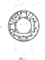
FIG. 2 is a side view showing a front drum of the drum inFIG. 1 ; -
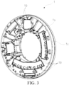
FIG. 3 is a three-dimensional view showing the front drum of the drum inFIG. 1 , showing a first side of the front drum; -
FIG. 4 is a three-dimensional view showing the front drum of the drum inFIG. 1 from another perspective, showing a second side of the front drum; -
FIG. 5 is a side view showing a rear drum of the drum inFIG. 1 ; -
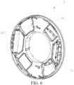
FIG. 6 is a three-dimensional view showing the rear drum of the drum inFIG. 1 , showing a first side of the rear drum; and -
FIG. 7 is a three-dimensional view showing the rear drum of the drum inFIG. 1 from another perspective, showing a rear side of the rear drum. -
- 100
- Drum
- 1
- Front drum
- 1a
- First side surface of front drum
- 1b
- Second side surface of front drum
- 1c
- Side end surface of front drum
- 10
- Front protrusion
- 11
- First system mounting area
- 111
- First tube mounting area
- 112
- First detector mounting area
- 12
- Second system mounting area
- 121
- Second tube mounting area
- 122
- Second detector mounting area
- 13
- Front flange
- 2
- Rear drum
- 2a
- First side surface of rear drum
- 2b
- Second side surface of rear drum
- 2c
- Side end surface of rear drum
- 20
- Rear protrusion
- 21
- First component mounting area
- 211
- High voltage generator mounting area
- 212
- High pressure tank mounting area
- 213
- tube cooling system mounting area
- 22
- Second component mounting area
- 221
- High voltage generator mounting area
- 222
- High pressure tank mounting area
- 223
- Tube cooling system mounting area
- 23
- Rear flange
- R1
- First X-ray path
- R2
- Second X-ray path
- α
- Included angle
- G1
- Groove on front drum
- G2
- Groove on rear drum
- P1
- Balance weight mounting position on front drum
- P2
- Balance weight mounting position on rear drum
- In order to make the purposes, technical solutions, and advantages of the invention clearer, the following embodiments are provided to describe the invention in further detail.
- Referring to
FIG. 1 to FIG. 7 , the invention provides adrum 100 for a dual source CT machine. Thedrum 100 is mounted to an outer rim of a bearing, and an inner rim of the bearing is mounted to a gantry of the dual source CT machine. Generally, thedrum 100 may include a ring-shapedfront drum 1 and a ring-shapedrear drum 2. Thefront drum 1 and therear drum 2 both may be made by casting aluminum. Such a casting has materials with a small weight and high strength. - Specifically, referring to
FIG. 2 to FIG. 4 , thefront drum 1 has afirst side surface 1a and asecond side surface 1b opposite to each other. A first system mounting area 11 configured for a first X-ray tube system to be mounted and a secondsystem mounting area 12 configured for a second X-ray tube system to be mounted are arranged on thefirst side surface 1a of thefront drum 1. Afront flange 13 extending in an axial direction (the axial direction herein is an axial direction of the drum, and since the drum includes thefront drum 1 and therear drum 2 arranged coaxially, the axial direction of the drum, in fact, an axial direction of the front drum, and an axial direction of the rear drum are the same) from an inner ring edge of thefront drum 1 is formed on thesecond side surface 1b of thefront drum 1. - Specifically, referring to
FIG. 5 to FIG. 7 , therear drum 2 has afirst side surface 2a and asecond side surface 2b opposite to each other. A firstcomponent mounting area 21 configured for a first set of components matching the first X-ray tube system to be mounted and a secondcomponent mounting area 22 configured for a second set of components matching the second X-ray tube system to be mounted are arranged on thefirst side surface 2a of therear drum 2. Arear flange 23 extending in the axial direction from an inner ring edge of therear drum 2 is formed on thesecond side surface 2b of therear drum 2. - The
front drum 1 and therear drum 2 are arranged coaxially, and thefront flange 13 and therear flange 23 face each other. Thefront drum 1 is connected to the bearing through thefront flange 13, and therear drum 2 is connected to the same bearing through therear flange 23. Specifically, thefront flange 13 and therear flange 23 may be connected to the bearing through bolts, for example. - Referring to
FIG. 2 , the first system mounting area 11 includes a firsttube mounting area 111 configured for a first tube to be mounted and a firstdetector mounting area 112 configured for a first detector to be mounted. A first X-ray path R1 is formed between the first tube and the first detector. The first tube and the first detector are not shown in the figure, and only the first X-ray path R1 is schematically shown with a broken line. The secondsystem mounting area 12 includes a secondtube mounting area 121 configured for a second tube to be mounted and a second detector mounting area 122 configured for a second detector to be mounted. A second X-ray path R2 is formed between the second tube and the second detector. The second tube and the second detector are not shown in the figure, and only the second X-ray path R2 is schematically shown with a broken line. The first X-ray path R1 and the second X-ray path R2 are both perpendicular to the axial direction (that is, in a radial direction of the drum), and an included angle α between the first X-ray path R1 and the second X-ray path R2 is between 45 degrees and 135 degrees. Preferably, the included angle α is 90 degrees. - Referring to
FIG. 3 , thefront drum 1 may include at least onefront protrusion 10 protruding from thefirst side surface 1a of thefront drum 1. The at least onefront protrusion 10 is arranged around and in contact with at least one X-ray tube system of the first X-ray tube system and the second X-ray tube system. Similarly, referring toFIG. 6 , therear drum 2 may include at least onerear protrusion 20 protruding from thefirst side surface 2a of therear drum 2. The at least onerear protrusion 20 is arranged around and in contact with at least one set of components of the first set of components and the second set of components. Specifically, at least one of the at least onefront protrusion 10 is arranged on a radial outer side of the at least one X-ray tube system; and/or at least one of the at least onerear protrusion 20 is arranged on a radial outer side of the at least one set of components. When thefront drum 1 and therear drum 2 rotate at a high speed, the electrical components mounted thereto bear an enormous centrifugal force. Through the arrangement of thefront protrusion 10 and therear protrusion 20, not only the centrifugal force on the electrical components can be born, but also the rigidity of the casting can be increased. In this way, the centrifugal force is converted to the casting material, thereby significantly improving the safety. - Referring to
FIG. 2 to FIG. 4 , each of the firsttube mounting area 111 and the secondtube mounting area 121 may have a through hole, so that the first tube mounted in the firsttube mounting area 111 and the second tube mounted in the secondtube mounting area 121 pass through the corresponding through holes and are mounted to thefront drum 1. In this way, a part of the first tube is located on a first side of thefront drum 1, and the other part is located on a second side of thefront drum 1, and a part of the second tube is located on the first side of thefront drum 1 and the other part is located on the second side of thefront drum 1, thereby facilitating the structural balance. - Referring to
FIG. 3 , a data transmission system may be mounted to aside end surface 1c of thefront drum 1 for data transmission with the electrical components. Referring toFIG. 4 , a balance weight (not shown) may be mounted at a position P1 on thesecond side surface 1b of thefront drum 1 staggered from the first system mounting area 11 and the secondsystem mounting area 12 located on thefirst side surface 1a of thefront drum 1, thereby facilitating the structural balance. - Referring to
FIG. 2 andFIG. 5 , one or more grooves G1, G2 may arranged on circumferential surfaces of inner holes of thefront drum 1 and therear drum 2, and the first X-ray tube system and the second X-ray tube system (not shown) may be respectively connected to the first set of components and the second set of components through cables extending through the one or more grooves G1, G2. - Referring to
FIG. 5 , each of the firstcomponent mounting area 21 and the secondcomponent mounting area 22 includes a high voltagegenerator mounting area tank mounting area system mounting area component mounting area 21 and the secondcomponent mounting area 22 are arranged symmetrically with respect to a center of therear drum 2. In this way, self-balance can be realized. Therefore, only a weight distribution of the drum and weight differences between the components need to be balanced and adjusted, thereby reducing the weight of the balance weight and reducing the balance adjustment time. - Referring to
FIG. 2 to FIG. 7 , due to the high power and the large amount of heat of the electrical components, a heat sink and/or a heat dissipation hole may be arranged on thefront drum 1 and/or therear drum 2, such as a heat dissipation hole in the firstdetector mounting area 112 or the second detector mounting area 122 extending through thefront drum 1. The heat dissipation hole is usually arranged near electrical components on the drum that generate a large amount of heat. In addition, the drum casting may be designed as a thin-walled frame structure to facilitate heat dissipation. - Referring to
FIG. 6 , a slip ring system may be mounted to a side end surface 2c of therear drum 2 for transmitting power and signals. Referring toFIG. 7 , a balance weight (not shown) is mounted at a position (P2) on thesecond side surface 2b of therear drum 2 staggered from the firstcomponent mounting area 21 and the secondcomponent mounting area 22 located on thefirst side surface 2a of therear drum 2. - Referring to
FIG. 4 andFIG. 7 , thefront drum 1 may include a plurality of support ribs connected between thesecond side surface 1b of thefront drum 1 and thefront flange 13 and spaced apart in a circumferential direction. Similarly, therear drum 2 may also include a plurality of support ribs connected between thesecond side surface 2b of therear drum 2 and therear flange 23 and spaced apart in the circumferential direction. The arrangement of the support ribs increases the structural stability of thefront drum 1 and the rear drum. - A dual source CT machine of the invention includes the drum in the above embodiment. The front drum and the rear drum of the drum are mounted to an outer rim of a bearing of the CT machine, and an inner rim of the bearing is mounted to a gantry of the CT machine.
- Through the drum of the invention including the
front drum 1 and therear drum 2, the scan time of the CT machine can be reduced, the scan efficiency can be improved, and clearer scanned images can be obtained. The drum of the invention has a light weight and low costs, is integrated with many functions, and has a more optimized structure.
Claims (10)
- A drum for a dual source CT machine, the drum (100) being mounted to an outer rim of a bearing, an inner rim of the bearing being mounted to a gantry of the dual source CT machine, and the drum (100) comprising:a ring-shaped front drum (1), wherein the ring-shaped front drum (1) has a first side surface (1a) and a second side surface (1b) opposite to each other, a first system mounting area (11) configured for a first X-ray tube system to be mounted and a second system mounting area (12) configured for a second X-ray tube system to be mounted are arranged on the first side surface (1a) of the front drum (1), and a front flange (13) extending in an axial direction from an inner ring edge of the front drum (1) is formed on the second side surface (1b) of the front drum (1); anda ring-shaped rear drum (2), wherein the rear drum (2) has a first side surface (2a) and a second side surface (2b) opposite to each other, a first component mounting area (21) configured for a first set of components matching the first X-ray tube system to be mounted and a second component mounting area (22) configured for a second set of components matching the second X-ray tube system to be mounted are arranged on the first side surface (2a) of the rear drum (2), and a rear flange (23) extending in the axial direction from an inner ring edge of the rear drum (2) is formed on the second side surface (2b) of the rear drum (2); andthe front drum (1) and the rear drum (2) are arranged coaxially, the front flange (13) and the rear flange (23) face each other, the front drum (1) is connected to the bearing through the front flange (13), and the rear drum (2) is connected to the bearing through the rear flange (23).
- The drum for a dual source CT machine according to claim 1, wherein the first system mounting area (11) comprises a first tube mounting area (111) configured for a first tube to be mounted and a first detector mounting area (112) configured for a first detector to be mounted, and a first X-ray path (R1) is formed between the first tube and the first detector; the second system mounting area (12) comprises a second tube mounting area (121) configured for a second tube to be mounted and a second detector mounting area (122) configured for a second detector to be mounted, and a second X-ray path (R2) is formed between the second tube and the second detector; and the first X-ray path (R1) and the second X-ray path (R2) are both perpendicular to the axial direction, and an included angle (α) between the first X-ray path (R1) and the second X-ray path (R2) is between 45 degrees and 135 degrees.
- The drum for a dual source CT machine according to claim 1 or 2, whereinthe front drum (1) comprises at least one front protrusion (10) protruding from the first side surface (1a)of the front drum (1), and the at least one front protrusion (10) is arranged around and in contact with at least one X-ray tube system of the first X-ray tube system and the second X-ray tube system; and/orthe rear drum (2) comprises at least one rear protrusion (20) protruding from the first side surface (2a) of the rear drum (2), and the at least one rear protrusion (20) is arranged around and in contact with at least one set of components of the first set of components and the second set of components.
- The drum for a dual source CT machine according to claim 3, whereinat least one of the at least one front protrusion (10) is arranged on a radial outer side of the at least one X-ray tube system; and/orat least one of the at least one rear protrusion (20) is arranged on a radial outer side of the at least one set of components.
- The drum for a dual source CT machine according to claim 2, wherein each of the first tube mounting area (111) and the second tube mounting area (121) has a through hole, so that the first tube mounted in the first tube mounting area (111) and the second tube mounted in the second tube mounting area (121) pass through the corresponding through holes and are mounted to the front drum (1).
- The drum for a dual source CT machine according to claim 1, wherein a balance weight is mounted at a position on the second side surface (1b) of the front drum (1) staggered from the first system mounting area (11) and the second system mounting area (12) located on the first side surface (1a) of the front drum (1).
- The drum for a dual source CT machine according to claim 1, wherein one or more grooves (G1, G2) are arranged on circumferential surfaces of inner holes of the front drum (1) and the rear drum (2), and the first X-ray tube system and the second X-ray tube system are respectively connected to the first set of components and the second set of components through cables extending through the one or more grooves (G1, G2).
- The drum for a dual source CT machine according to claim 1, wherein each of the first component mounting area (21) and the second component mounting area (22) comprises a high voltage generator mounting area (211, 221) configured for a high voltage generator to be mounted, a high pressure tank mounting area (212, 222) configured for a high pressure tank to be mounted, and a tube cooling system mounting area (213, 223) configured for a tube cooling system to be mounted, and the first component mounting area (21) and the second component mounting area (22) are arranged symmetrically with respect to a center of the rear drum (2).
- The drum for a dual source CT machine according to claim 1, wherein a balance weight is mounted at a position on the second side surface (2b) of the rear drum (2) staggered from the first component mounting area (21) and the second component mounting area (22) located on the first side surface (2a) of the rear drum (2).
- A dual source CT machine, comprising the drum for a dual source CT machine according to any of claims 1 to 9.
Applications Claiming Priority (2)
| Application Number | Priority Date | Filing Date | Title |
|---|---|---|---|
| CN202221397178.0U CN217827894U (en) | 2022-05-30 | 2022-05-30 | Double-source CT machine and turntable for same |
| PCT/CN2023/093294 WO2023231729A1 (en) | 2022-05-30 | 2023-05-10 | Dual source ct machine and drum for dual source ct machine |
Publications (3)
| Publication Number | Publication Date |
|---|---|
| EP4472514A1 EP4472514A1 (en) | 2024-12-11 |
| EP4472514C0 EP4472514C0 (en) | 2025-03-12 |
| EP4472514B1 true EP4472514B1 (en) | 2025-03-12 |
Family
ID=84021611
Family Applications (1)
| Application Number | Title | Priority Date | Filing Date |
|---|---|---|---|
| EP23729654.6A Active EP4472514B1 (en) | 2022-05-30 | 2023-05-10 | Dual source ct machine and drum for dual source ct machine |
Country Status (4)
| Country | Link |
|---|---|
| US (1) | US20250345016A1 (en) |
| EP (1) | EP4472514B1 (en) |
| CN (1) | CN217827894U (en) |
| WO (1) | WO2023231729A1 (en) |
Families Citing this family (1)
| Publication number | Priority date | Publication date | Assignee | Title |
|---|---|---|---|---|
| CN116763329B (en) * | 2022-12-28 | 2024-07-02 | 清华大学 | CT imaging system and CT detection device |
Family Cites Families (3)
| Publication number | Priority date | Publication date | Assignee | Title |
|---|---|---|---|---|
| US9538963B2 (en) * | 2013-03-15 | 2017-01-10 | Aktiebolaget Skf | Diagnostic scanning apparatus |
| DE102014217275A1 (en) * | 2014-08-29 | 2016-03-03 | Siemens Aktiengesellschaft | Rotor for a gantry of a computed tomography device |
| US10695586B2 (en) * | 2016-11-15 | 2020-06-30 | Reflexion Medical, Inc. | System for emission-guided high-energy photon delivery |
-
2022
- 2022-05-30 CN CN202221397178.0U patent/CN217827894U/en active Active
-
2023
- 2023-05-10 EP EP23729654.6A patent/EP4472514B1/en active Active
- 2023-05-10 WO PCT/CN2023/093294 patent/WO2023231729A1/en not_active Ceased
- 2023-05-10 US US18/869,150 patent/US20250345016A1/en active Pending
Also Published As
| Publication number | Publication date |
|---|---|
| EP4472514C0 (en) | 2025-03-12 |
| EP4472514A1 (en) | 2024-12-11 |
| US20250345016A1 (en) | 2025-11-13 |
| CN217827894U (en) | 2022-11-18 |
| WO2023231729A1 (en) | 2023-12-07 |
Similar Documents
| Publication | Publication Date | Title |
|---|---|---|
| US8781061B2 (en) | X-ray CT rotary apparatus | |
| US8681930B2 (en) | High speed rotating gantry | |
| JP4340537B2 (en) | CT detector module with radiation shield for processing circuit | |
| US7508904B2 (en) | X-ray CT apparatus | |
| US5493599A (en) | Off-focal radiation limiting precollimator and adjustable ring collimator for x-ray CT scanners | |
| WO2023231729A1 (en) | Dual source ct machine and drum for dual source ct machine | |
| CN101163367A (en) | Method and Apparatus for High Speed Scanners | |
| CN102157323B (en) | For the X-ray equipment of wide cut CT art | |
| US20100072384A1 (en) | Electron beam scanner | |
| US20180110481A1 (en) | Ct machine and rotator thereof | |
| CN210697659U (en) | Computed tomography gantry and computed tomography apparatus | |
| WO2009081327A2 (en) | A rotor and x-ray ct scanners | |
| US11039798B2 (en) | Rotating structure for radiation imaging modalities | |
| US20050220382A1 (en) | Fixing structure for rolling bearing | |
| US20050226385A1 (en) | X-ray tube for a computed tomography system and method | |
| US12383211B2 (en) | X-ray CT apparatus and attaching method and detaching method of units within gantry of x-ray CT apparatus | |
| EP2983590B1 (en) | Computerized tomography (ct) imaging system with improved x-ray tube mount | |
| EP4643782A1 (en) | Ct imaging system and ct detection apparatus | |
| EP4234966B1 (en) | Support frame for ct slip-ring bearing | |
| US4935948A (en) | X-ray tube noise reduction by mounting a ring mass | |
| CN209878627U (en) | Detector box and security inspection equipment | |
| CN209878626U (en) | Detector box and security inspection equipment | |
| JP7171319B2 (en) | X-ray CT device | |
| US20240407740A1 (en) | Integrated computed tomography rotating base with an integrated drive system | |
| CN111487264A (en) | Detector box and security inspection equipment |
Legal Events
| Date | Code | Title | Description |
|---|---|---|---|
| STAA | Information on the status of an ep patent application or granted ep patent |
Free format text: STATUS: UNKNOWN |
|
| STAA | Information on the status of an ep patent application or granted ep patent |
Free format text: STATUS: THE INTERNATIONAL PUBLICATION HAS BEEN MADE |
|
| PUAI | Public reference made under article 153(3) epc to a published international application that has entered the european phase |
Free format text: ORIGINAL CODE: 0009012 |
|
| STAA | Information on the status of an ep patent application or granted ep patent |
Free format text: STATUS: REQUEST FOR EXAMINATION WAS MADE |
|
| 17P | Request for examination filed |
Effective date: 20240903 |
|
| AK | Designated contracting states |
Kind code of ref document: A1 Designated state(s): AL AT BE BG CH CY CZ DE DK EE ES FI FR GB GR HR HU IE IS IT LI LT LU LV MC ME MK MT NL NO PL PT RO RS SE SI SK SM TR |
|
| GRAP | Despatch of communication of intention to grant a patent |
Free format text: ORIGINAL CODE: EPIDOSNIGR1 |
|
| STAA | Information on the status of an ep patent application or granted ep patent |
Free format text: STATUS: GRANT OF PATENT IS INTENDED |
|
| INTG | Intention to grant announced |
Effective date: 20241216 |
|
| RIN1 | Information on inventor provided before grant (corrected) |
Inventor name: ZHENG, JING MING Inventor name: ZHU, TIE BIAO Inventor name: FAN, LI MEI |
|
| GRAS | Grant fee paid |
Free format text: ORIGINAL CODE: EPIDOSNIGR3 |
|
| GRAA | (expected) grant |
Free format text: ORIGINAL CODE: 0009210 |
|
| STAA | Information on the status of an ep patent application or granted ep patent |
Free format text: STATUS: THE PATENT HAS BEEN GRANTED |
|
| AK | Designated contracting states |
Kind code of ref document: B1 Designated state(s): AL AT BE BG CH CY CZ DE DK EE ES FI FR GB GR HR HU IE IS IT LI LT LU LV MC ME MK MT NL NO PL PT RO RS SE SI SK SM TR |
|
| DAV | Request for validation of the european patent (deleted) | ||
| DAX | Request for extension of the european patent (deleted) | ||
| REG | Reference to a national code |
Ref country code: GB Ref legal event code: FG4D |
|
| REG | Reference to a national code |
Ref country code: CH Ref legal event code: EP |
|
| REG | Reference to a national code |
Ref country code: DE Ref legal event code: R096 Ref document number: 602023002420 Country of ref document: DE |
|
| REG | Reference to a national code |
Ref country code: IE Ref legal event code: FG4D |
|
| U01 | Request for unitary effect filed |
Effective date: 20250318 |
|
| U07 | Unitary effect registered |
Designated state(s): AT BE BG DE DK EE FI FR IT LT LU LV MT NL PT RO SE SI Effective date: 20250325 |
|
| U20 | Renewal fee for the european patent with unitary effect paid |
Year of fee payment: 3 Effective date: 20250520 |
|
| PG25 | Lapsed in a contracting state [announced via postgrant information from national office to epo] |
Ref country code: RS Free format text: LAPSE BECAUSE OF FAILURE TO SUBMIT A TRANSLATION OF THE DESCRIPTION OR TO PAY THE FEE WITHIN THE PRESCRIBED TIME-LIMIT Effective date: 20250612 |
|
| PG25 | Lapsed in a contracting state [announced via postgrant information from national office to epo] |
Ref country code: ES Free format text: LAPSE BECAUSE OF FAILURE TO SUBMIT A TRANSLATION OF THE DESCRIPTION OR TO PAY THE FEE WITHIN THE PRESCRIBED TIME-LIMIT Effective date: 20250312 |
|
| PG25 | Lapsed in a contracting state [announced via postgrant information from national office to epo] |
Ref country code: NO Free format text: LAPSE BECAUSE OF FAILURE TO SUBMIT A TRANSLATION OF THE DESCRIPTION OR TO PAY THE FEE WITHIN THE PRESCRIBED TIME-LIMIT Effective date: 20250612 |
|
| PG25 | Lapsed in a contracting state [announced via postgrant information from national office to epo] |
Ref country code: HR Free format text: LAPSE BECAUSE OF FAILURE TO SUBMIT A TRANSLATION OF THE DESCRIPTION OR TO PAY THE FEE WITHIN THE PRESCRIBED TIME-LIMIT Effective date: 20250312 |
|
| PG25 | Lapsed in a contracting state [announced via postgrant information from national office to epo] |
Ref country code: GR Free format text: LAPSE BECAUSE OF FAILURE TO SUBMIT A TRANSLATION OF THE DESCRIPTION OR TO PAY THE FEE WITHIN THE PRESCRIBED TIME-LIMIT Effective date: 20250613 |
|
| PG25 | Lapsed in a contracting state [announced via postgrant information from national office to epo] |
Ref country code: SM Free format text: LAPSE BECAUSE OF FAILURE TO SUBMIT A TRANSLATION OF THE DESCRIPTION OR TO PAY THE FEE WITHIN THE PRESCRIBED TIME-LIMIT Effective date: 20250312 |
|
| PG25 | Lapsed in a contracting state [announced via postgrant information from national office to epo] |
Ref country code: PL Free format text: LAPSE BECAUSE OF FAILURE TO SUBMIT A TRANSLATION OF THE DESCRIPTION OR TO PAY THE FEE WITHIN THE PRESCRIBED TIME-LIMIT Effective date: 20250312 |
|
| PG25 | Lapsed in a contracting state [announced via postgrant information from national office to epo] |
Ref country code: CZ Free format text: LAPSE BECAUSE OF FAILURE TO SUBMIT A TRANSLATION OF THE DESCRIPTION OR TO PAY THE FEE WITHIN THE PRESCRIBED TIME-LIMIT Effective date: 20250312 |
|
| PG25 | Lapsed in a contracting state [announced via postgrant information from national office to epo] |
Ref country code: SK Free format text: LAPSE BECAUSE OF FAILURE TO SUBMIT A TRANSLATION OF THE DESCRIPTION OR TO PAY THE FEE WITHIN THE PRESCRIBED TIME-LIMIT Effective date: 20250312 |
|
| PG25 | Lapsed in a contracting state [announced via postgrant information from national office to epo] |
Ref country code: IS Free format text: LAPSE BECAUSE OF FAILURE TO SUBMIT A TRANSLATION OF THE DESCRIPTION OR TO PAY THE FEE WITHIN THE PRESCRIBED TIME-LIMIT Effective date: 20250712 |
|
| PLBE | No opposition filed within time limit |
Free format text: ORIGINAL CODE: 0009261 |
|
| STAA | Information on the status of an ep patent application or granted ep patent |
Free format text: STATUS: NO OPPOSITION FILED WITHIN TIME LIMIT |
|
| REG | Reference to a national code |
Ref country code: CH Ref legal event code: L10 Free format text: ST27 STATUS EVENT CODE: U-0-0-L10-L00 (AS PROVIDED BY THE NATIONAL OFFICE) Effective date: 20260121 |
|
| PG25 | Lapsed in a contracting state [announced via postgrant information from national office to epo] |
Ref country code: MC Free format text: LAPSE BECAUSE OF FAILURE TO SUBMIT A TRANSLATION OF THE DESCRIPTION OR TO PAY THE FEE WITHIN THE PRESCRIBED TIME-LIMIT Effective date: 20250312 |
|
| 26N | No opposition filed |
Effective date: 20251215 |
|
| PG25 | Lapsed in a contracting state [announced via postgrant information from national office to epo] |
Ref country code: IE Free format text: LAPSE BECAUSE OF NON-PAYMENT OF DUE FEES Effective date: 20250510 |
|
| U20 | Renewal fee for the european patent with unitary effect paid |
Year of fee payment: 4 Effective date: 20260520 |
|
| PG25 | Lapsed in a contracting state [announced via postgrant information from national office to epo] |
Ref country code: CY Free format text: LAPSE BECAUSE OF FAILURE TO SUBMIT A TRANSLATION OF THE DESCRIPTION OR TO PAY THE FEE WITHIN THE PRESCRIBED TIME-LIMIT Effective date: 20250312 |