EP4472369A1 - Electronic device - Google Patents
Electronic device Download PDFInfo
- Publication number
- EP4472369A1 EP4472369A1 EP24169243.3A EP24169243A EP4472369A1 EP 4472369 A1 EP4472369 A1 EP 4472369A1 EP 24169243 A EP24169243 A EP 24169243A EP 4472369 A1 EP4472369 A1 EP 4472369A1
- Authority
- EP
- European Patent Office
- Prior art keywords
- component
- electronic component
- partition wall
- electrical connection
- opening
- Prior art date
- Legal status (The legal status is an assumption and is not a legal conclusion. Google has not performed a legal analysis and makes no representation as to the accuracy of the status listed.)
- Pending
Links
Images
Classifications
-
- H—ELECTRICITY
- H05—ELECTRIC TECHNIQUES NOT OTHERWISE PROVIDED FOR
- H05K—PRINTED CIRCUITS; CASINGS OR CONSTRUCTIONAL DETAILS OF ELECTRIC APPARATUS; MANUFACTURE OF ASSEMBLAGES OF ELECTRICAL COMPONENTS
- H05K7/00—Constructional details common to different types of electric apparatus
- H05K7/14—Mounting supporting structure in casing or on frame or rack
- H05K7/1462—Mounting supporting structure in casing or on frame or rack for programmable logic controllers [PLC] for automation or industrial process control
-
- H—ELECTRICITY
- H05—ELECTRIC TECHNIQUES NOT OTHERWISE PROVIDED FOR
- H05K—PRINTED CIRCUITS; CASINGS OR CONSTRUCTIONAL DETAILS OF ELECTRIC APPARATUS; MANUFACTURE OF ASSEMBLAGES OF ELECTRICAL COMPONENTS
- H05K5/00—Casings, cabinets or drawers for electric apparatus
- H05K5/02—Details
- H05K5/0217—Mechanical details of casings
-
- H—ELECTRICITY
- H01—ELECTRIC ELEMENTS
- H01R—ELECTRICALLY-CONDUCTIVE CONNECTIONS; STRUCTURAL ASSOCIATIONS OF A PLURALITY OF MUTUALLY-INSULATED ELECTRICAL CONNECTING ELEMENTS; COUPLING DEVICES; CURRENT COLLECTORS
- H01R12/00—Structural associations of a plurality of mutually-insulated electrical connecting elements, specially adapted for printed circuits, e.g. printed circuit boards [PCB], flat or ribbon cables, or like generally planar structures, e.g. terminal strips, terminal blocks; Coupling devices specially adapted for printed circuits, flat or ribbon cables, or like generally planar structures; Terminals specially adapted for contact with, or insertion into, printed circuits, flat or ribbon cables, or like generally planar structures
- H01R12/70—Coupling devices
- H01R12/71—Coupling devices for rigid printing circuits or like structures
- H01R12/712—Coupling devices for rigid printing circuits or like structures co-operating with the surface of the printed circuit or with a coupling device exclusively provided on the surface of the printed circuit
- H01R12/716—Coupling device provided on the PCB
-
- H—ELECTRICITY
- H01—ELECTRIC ELEMENTS
- H01R—ELECTRICALLY-CONDUCTIVE CONNECTIONS; STRUCTURAL ASSOCIATIONS OF A PLURALITY OF MUTUALLY-INSULATED ELECTRICAL CONNECTING ELEMENTS; COUPLING DEVICES; CURRENT COLLECTORS
- H01R13/00—Details of coupling devices of the kinds covered by groups H01R12/70 or H01R24/00 - H01R33/00
- H01R13/73—Means for mounting coupling parts to apparatus or structures, e.g. to a wall
- H01R13/74—Means for mounting coupling parts in openings of a panel
-
- H—ELECTRICITY
- H01—ELECTRIC ELEMENTS
- H01R—ELECTRICALLY-CONDUCTIVE CONNECTIONS; STRUCTURAL ASSOCIATIONS OF A PLURALITY OF MUTUALLY-INSULATED ELECTRICAL CONNECTING ELEMENTS; COUPLING DEVICES; CURRENT COLLECTORS
- H01R24/00—Two-part coupling devices, or either of their cooperating parts, characterised by their overall structure
-
- H—ELECTRICITY
- H01—ELECTRIC ELEMENTS
- H01R—ELECTRICALLY-CONDUCTIVE CONNECTIONS; STRUCTURAL ASSOCIATIONS OF A PLURALITY OF MUTUALLY-INSULATED ELECTRICAL CONNECTING ELEMENTS; COUPLING DEVICES; CURRENT COLLECTORS
- H01R31/00—Coupling parts supported only by co-operation with counterpart
- H01R31/06—Intermediate parts for linking two coupling parts, e.g. adapter
-
- H—ELECTRICITY
- H05—ELECTRIC TECHNIQUES NOT OTHERWISE PROVIDED FOR
- H05K—PRINTED CIRCUITS; CASINGS OR CONSTRUCTIONAL DETAILS OF ELECTRIC APPARATUS; MANUFACTURE OF ASSEMBLAGES OF ELECTRICAL COMPONENTS
- H05K5/00—Casings, cabinets or drawers for electric apparatus
- H05K5/02—Details
- H05K5/0247—Electrical details of casings, e.g. terminals, passages for cables or wiring
-
- H—ELECTRICITY
- H05—ELECTRIC TECHNIQUES NOT OTHERWISE PROVIDED FOR
- H05K—PRINTED CIRCUITS; CASINGS OR CONSTRUCTIONAL DETAILS OF ELECTRIC APPARATUS; MANUFACTURE OF ASSEMBLAGES OF ELECTRICAL COMPONENTS
- H05K5/00—Casings, cabinets or drawers for electric apparatus
- H05K5/02—Details
- H05K5/03—Covers
Definitions
- the present disclosure relates to an electronic device.
- a known electronic device includes a container, a partition wall dividing a space within the container, a through-hole provided in the partition wall, an electrical connection component attached to the partition wall and having an insertion portion inserted into the through-hole, a first electronic component attached to the electrical connection component on one side of the partition wall, and a second electronic component attached to the electrical connection component on the other side of the partition wall, wherein the first electronic component and the second electronic component can be electrically connected to each other via the electrical connection component by each being attached to the electrical connection component.
- PTL Patent Literature
- An electronic device such as the one described above preferably allows the electrical connection component, the first electronic component, and the second electronic component to be removed separately from the container during disposal, maintenance, or the like.
- an electronic device such that an electrical connection component, a first electronic component, and a second electronic component can be separately removed from a container can be provided.
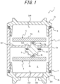
- FIG. 1 is a cross-sectional diagram illustrating an electronic device in an embodiment of the present disclosure.
- an electronic device 1 includes a container 2, a partition wall 2a1 dividing a space within the container 2, a through-hole 2a2 provided in the partition wall 2a1, an electrical connection component 3 attached to the partition wall 2a1 so as to be removable from the container 2 and having an insertion portion 3a inserted into the through-hole 2a2, a first electronic component 4 attachable to the electrical connection component 3 on one side of the partition wall 2a1 so as to be removable from the container 2, and a second electronic component 5 attachable to the electrical connection component 3 on another side of the partition wall 2a1 so as to be removable from the container 2.
- the first electronic component 4 and the second electronic component 5 can be electrically connected to each other via the electrical connection component 3 by each being attached to the electrical connection component 3.
- the first electronic component 4 can be detached from the electrical connection component 3 on one side of the partition wall 2a1 and removed from the container 2
- the second electronic component 5 can be detached from the electrical connection component 3 on the other side of the partition wall 2a1 and removed from the container 2
- the electrical connection component 3 attached to the partition wall 2a1 can be removed from the container 2.
- the electrical connection component 3, the first electronic component 4, and the second electronic component 5 can therefore be separately removed from the container 2.
- the container 2, the electrical connection component 3, the first electronic component 4, and the second electronic component 5 can be sorted by material at the time of disposal, for example, and in a case in which the first electronic component 4 and the second electronic component 5 are of different materials, the first electronic component 4 and the second electronic component 5 can be sorted.
- the electrical connection component 3, the first electronic component 4, or the second electronic component 5 can, for example, be individually removed from the container 2 for repair or replacement as necessary during periodic maintenance, repair, or the like.
- the electrical connection component 3 enables power supply, analog or digital communication, or any combination thereof, for example, between the first electronic component 4 and the second electronic component 5 via the electrical connection between the first electronic component 4 and the second electronic component 5.
- the container 2 includes a container body 2a, made of metal or the like, forming a first opening 2a3 through which the first electronic component 4 can pass at the one side of the partition wall 2a1, and a first lid 2b capable of opening the first opening 2a3.
- a closed first chamber 6 can be formed on one side of the partition wall 2a1 by closing the first opening 2a3 of the container body 2a with the first lid 2b, and the first chamber 6 can be opened by the first lid 2b to remove the first electronic component 4 from the container 2 through the first opening 2a3.
- the electronic device 1 includes a first lid sealing member 7 formed, for example, of an elastic material that seals the first chamber 6 by the first opening 2a3 of the container body 2a being closed by the first lid 2b. According to this configuration, the sealing property of the first lid 2b can be improved.
- the first lid 2b includes a lid body 2b 1 made of metal or the like and a transparent window 2b2 made of glass or the like. According to this configuration, the inside of the first chamber 6 is visible from the outside while the first chamber 6 is closed.
- the first opening 2a3 is configured to allow the electrical connection component 3 to pass through the first opening 2a3. According to this configuration, the electrical connection component 3 can be removed from the container 2 through the first opening 2a3 by opening the first lid 2b.
- the container body 2a forms a second opening 2a4 through which the second electronic component 5 can pass at the other side of the partition wall 2a1, and the container 2 includes a second lid 2c capable of opening the second opening 2a4.
- a closed second chamber 8 can be formed on the other side of the partition wall 2a1 by closing the second opening 2a4 of the container body 2a with the second lid 2c, and the second chamber 8 can be opened by the second lid 2c to remove the second electronic component 5 from the container 2 through the second opening 2a4.
- the electronic device 1 includes a second lid sealing member 9 formed, for example, of an elastic material that seals the second chamber 8 by the second opening 2a4 of the container body 2a being closed by the second lid 2c. According to this configuration, the sealing property of the second lid 2c can be improved.
- the first electronic component 4 may be configured to be attachable to the container body 2a by a fixing member for the first electronic component, such as a screw. According to this configuration, the first electronic component 4 can be fixed to the container body 2a by the fixing member for the first electronic component, and the fixation by the fixing member for the first electronic component can be released for detachment of the first electronic component 4 from the container body 2a and removal from the container 2.
- a fixing member for the first electronic component such as a screw.
- the electrical connection component 3 may be configured to be attachable to the container body 2a by a fixing member for the electrical connection component, such as a screw. According to this configuration, the electrical connection component 3 can be fixed to the container body 2a by the fixing member for the electrical connection component, and the fixation by the fixing member for the electrical connection component can be released for detachment of the electrical connection component 3 from the container body 2a and removal from the container 2.
- the second electronic component 5 may be configured to be attachable to the container body 2a by a fixing member for the second electronic component, such as a screw. According to this configuration, the second electronic component 5 can be fixed to the container body 2a by the fixing member for the second electronic component, and the fixation by the fixing member for the second electronic component can be released for detachment of the second electronic component 5 from the container body 2a and removal from the container 2.
- a fixing member for the second electronic component such as a screw.
- One of the first electronic component 4 and the second electronic component 5 may be an amplifier component, and the other of the first electronic component 4 and the second electronic component 5 may be a terminal component.
- the amplifier component and the terminal component can be sorted at the time of disposal.
- the amplifier component transmits an electrical signal to the terminal component, for example.
- the terminal component transmits electric power to the amplifier component, for example.
- the first electronic component 4 includes a substrate 4a and a first connector 4b mounted on the substrate 4a, and the first electronic component 4 is fixed to the partition wall 2a1 by being attached to the electrical connection component 3 via the first connector 4b. According to this configuration, mounting and electrical connection of the first electronic component 4 to the electrical connection component 3 can be achieved by a simple structure using the first connector 4b mounted on the substrate 4a.
- the second electronic component 5 includes a substrate 5a and a second connector 5b mounted on the substrate 5a, and the second electronic component 5 is fixed to the partition wall 2a1 by being attached to the electrical connection component 3 via the second connector 5b. According to this configuration, mounting and electrical connection of the second electronic component 5 to the electrical connection component 3 can be achieved by a simple structure using the second connector 5b mounted on the substrate 5a.
- the electronic device 1 includes a partition wall sealing member 10 that surrounds the insertion portion 3a of the electrical connection component 3 so as to seal the gap between the partition wall 2a1 and the electrical connection component 3 and that is formed of an elastic material, for example. According to this configuration, the sealing property of the partition wall 2a1 can be improved.
- the container 2 includes the container body 2a forming the first opening 2a3 through which the first electronic component 4 can pass at the one side of the partition wall 2a1 and the second opening 2a4 through which the second electronic component 5 can pass at the other side of the partition wall 2a1, the first lid 2b capable of opening the first opening 2a3, and the second lid 2c capable of opening the second opening 2a4.
- the container body 2a includes the partition wall 2a1, and the container body 2a, the first lid 2b, the second lid 2c, and the electrical connection component 3 form an explosion-proof structure. According to the above configuration, an electronic device 1 that satisfies explosion-proof regulations can be realized.
- the electronic device 1 is, for example, a differential pressure/pressure transmitter, a temperature transmitter, an electromagnetic, vortex, Coriolis, or ultrasonic flow meter, or the like.
- the electrical connection between the first electronic component 4 and the second electronic component 5 of the electronic device 1 via the electrical connection component 3 is a 2-wire system, for example, and achieves analog communication, such as 4-20 mA current output, or digital communication, such as FF or Profi, by a power supply from a commercial power source or the like, for example.
- the electronic device 1 may be configured as a field device. According to this configuration, a field device such that the electrical connection component 3, the first electronic component 4, and the second electronic component 5 can be separately removed from the container 2 can be achieved.
- Field devices are electronic devices 1 used in a plant.
- the plant is an industrial plant such as a chemical plant; a plant for managing a well site, such as a gas field or oil field, and the surrounding area; a plant for managing power generation such as hydroelectric power, thermal power, nuclear power, or the like; a plant for managing environmental power generation such as solar power, wind power, or the like; a plant for managing water and sewage, a dam, or the like; or another type of plant.
- Field devices are often composed of parts made of different materials such as metals and resins, which can be disassembled, sorted, and recovered for reuse if necessary. Hundreds of thousands to millions of field devices are produced per year in the market overall, and it is assumed that a similar number of field devices are disposed of. Whether field devices can be sorted at the time of disposal is of great importance in terms of impact on the global environment.
Landscapes
- Engineering & Computer Science (AREA)
- Microelectronics & Electronic Packaging (AREA)
- Automation & Control Theory (AREA)
- Casings For Electric Apparatus (AREA)
Abstract
An electronic device includes a container, a partition wall dividing a space within the container, a through-hole provided in the partition wall, an electrical connection component attached to the partition wall so as to be removable from the container and having an insertion portion inserted into the through-hole, a first electronic component attachable to the electrical connection component on one side of the partition wall so as to be removable from the container, and a second electronic component attachable to the electrical connection component on another side of the partition wall so as to be removable from the container. The first electronic component and the second electronic component can be electrically connected to each other via the electrical connection component by each being attached to the electrical connection component.
Description
- The present disclosure relates to an electronic device.
- A known electronic device includes a container, a partition wall dividing a space within the container, a through-hole provided in the partition wall, an electrical connection component attached to the partition wall and having an insertion portion inserted into the through-hole, a first electronic component attached to the electrical connection component on one side of the partition wall, and a second electronic component attached to the electrical connection component on the other side of the partition wall, wherein the first electronic component and the second electronic component can be electrically connected to each other via the electrical connection component by each being attached to the electrical connection component. See, for example, Patent Literature (PTL) 1.
- PTL 1:
JP S53-031449 U - An electronic device such as the one described above preferably allows the electrical connection component, the first electronic component, and the second electronic component to be removed separately from the container during disposal, maintenance, or the like.
- It would be helpful to provide an electronic device such that an electrical connection component, a first electronic component, and a second electronic component can be separately removed from a container.
- Aspects of the present disclosure are as follows.
- [1] An electronic device including:
- a container;
- a partition wall dividing a space within the container;
- a through-hole provided in the partition wall;
- an electrical connection component attached to the partition wall so as to be removable from the container and having an insertion portion inserted into the through-hole;
- a first electronic component attachable to the electrical connection component on one side of the partition wall so as to be removable from the container; and
- a second electronic component attachable to the electrical connection component on another side of the partition wall so as to be removable from the container, wherein
- the first electronic component and the second electronic component can be electrically connected to each other via the electrical connection component by each being attached to the electrical connection component.
- [2] The electronic device recited in [1], wherein the container includes
- a container body forming a first opening through which the first electronic component can pass at the one side of the partition wall, and
- a first lid capable of opening the first opening.
- [3] The electronic device recited in [2], wherein the first opening is configured to allow the electrical connection component to pass through the first opening.
- [4] The electronic device recited in [2] or [3], wherein
- the container body forms a second opening through which the second electronic component can pass at the other side of the partition wall, and
- the container includes a second lid capable of opening the second opening.
- [5] The electronic device recited in any one of [1] to [4], wherein one of the first electronic component and the second electronic component is an amplifier component and the other of the first electronic component and the second electronic component is a terminal component.
- [6] The electronic device recited in any one of [1] to [5], wherein the first electronic component includes a substrate and a first connector mounted on the substrate, and the first electronic component is fixed to the partition wall by being attached to the electrical connection component via the first connector.
- [7] The electronic device recited in any one of [1] to [6], wherein the second electronic component includes a substrate and a second connector mounted on the substrate, and the second electronic component is fixed to the partition wall by being attached to the electrical connection component via the second connector.
- [8] The electronic device recited in any one of [1] to [7], further including a partition wall sealing member surrounding the insertion portion of the electrical connection component so as to seal a gap between the partition wall and the electrical connection component.
- [9] The electronic device recited in any one of [1] to [8], wherein
- the container includes a container body forming a first opening through which the first electronic component can pass at the one side of the partition wall and a second opening through which the second electronic component can pass at the other side of the partition wall, a first lid capable of opening the first opening, and a second lid capable of opening the second opening,
- the container body includes the partition wall, and
- the container body, the first lid, the second lid, and the electrical connection component form an explosion-proof structure.
- [10] The electronic device recited in any one of [1] to [9], wherein the electronic device is configured as a field device.
- According to the present disclosure, an electronic device such that an electrical connection component, a first electronic component, and a second electronic component can be separately removed from a container can be provided.
- In the accompanying drawings:
FIG. 1 is a cross-sectional diagram illustrating an electronic device in an embodiment of the present disclosure. - Embodiments of the present disclosure are illustrated below with reference to the drawings.
- As illustrated in
FIG. 1 , in an embodiment of the present disclosure, an electronic device 1 includes acontainer 2, a partition wall 2a1 dividing a space within thecontainer 2, a through-hole 2a2 provided in the partition wall 2a1, anelectrical connection component 3 attached to the partition wall 2a1 so as to be removable from thecontainer 2 and having aninsertion portion 3a inserted into the through-hole 2a2, a firstelectronic component 4 attachable to theelectrical connection component 3 on one side of the partition wall 2a1 so as to be removable from thecontainer 2, and a secondelectronic component 5 attachable to theelectrical connection component 3 on another side of the partition wall 2a1 so as to be removable from thecontainer 2. The firstelectronic component 4 and the secondelectronic component 5 can be electrically connected to each other via theelectrical connection component 3 by each being attached to theelectrical connection component 3. - According to the above configuration, the first
electronic component 4 can be detached from theelectrical connection component 3 on one side of the partition wall 2a1 and removed from thecontainer 2, the secondelectronic component 5 can be detached from theelectrical connection component 3 on the other side of the partition wall 2a1 and removed from thecontainer 2, and theelectrical connection component 3 attached to the partition wall 2a1 can be removed from thecontainer 2. Theelectrical connection component 3, the firstelectronic component 4, and the secondelectronic component 5 can therefore be separately removed from thecontainer 2. As a result, thecontainer 2, theelectrical connection component 3, the firstelectronic component 4, and the secondelectronic component 5 can be sorted by material at the time of disposal, for example, and in a case in which the firstelectronic component 4 and the secondelectronic component 5 are of different materials, the firstelectronic component 4 and the secondelectronic component 5 can be sorted. Furthermore, theelectrical connection component 3, the firstelectronic component 4, or the secondelectronic component 5 can, for example, be individually removed from thecontainer 2 for repair or replacement as necessary during periodic maintenance, repair, or the like. - The
electrical connection component 3 enables power supply, analog or digital communication, or any combination thereof, for example, between the firstelectronic component 4 and the secondelectronic component 5 via the electrical connection between the firstelectronic component 4 and the secondelectronic component 5. - The
container 2 includes acontainer body 2a, made of metal or the like, forming a first opening 2a3 through which the firstelectronic component 4 can pass at the one side of the partition wall 2a1, and afirst lid 2b capable of opening the first opening 2a3. According to this configuration, a closedfirst chamber 6 can be formed on one side of the partition wall 2a1 by closing the first opening 2a3 of thecontainer body 2a with thefirst lid 2b, and thefirst chamber 6 can be opened by thefirst lid 2b to remove the firstelectronic component 4 from thecontainer 2 through the first opening 2a3. - The electronic device 1 includes a first lid sealing member 7 formed, for example, of an elastic material that seals the
first chamber 6 by the first opening 2a3 of thecontainer body 2a being closed by thefirst lid 2b. According to this configuration, the sealing property of thefirst lid 2b can be improved. - The
first lid 2b includes alid body 2b 1 made of metal or the like and a transparent window 2b2 made of glass or the like. According to this configuration, the inside of thefirst chamber 6 is visible from the outside while thefirst chamber 6 is closed. - The first opening 2a3 is configured to allow the
electrical connection component 3 to pass through the first opening 2a3. According to this configuration, theelectrical connection component 3 can be removed from thecontainer 2 through the first opening 2a3 by opening thefirst lid 2b. - The
container body 2a forms a second opening 2a4 through which the secondelectronic component 5 can pass at the other side of the partition wall 2a1, and thecontainer 2 includes asecond lid 2c capable of opening the second opening 2a4. According to this configuration, a closedsecond chamber 8 can be formed on the other side of the partition wall 2a1 by closing the second opening 2a4 of thecontainer body 2a with thesecond lid 2c, and thesecond chamber 8 can be opened by thesecond lid 2c to remove the secondelectronic component 5 from thecontainer 2 through the second opening 2a4. - The electronic device 1 includes a second
lid sealing member 9 formed, for example, of an elastic material that seals thesecond chamber 8 by the second opening 2a4 of thecontainer body 2a being closed by thesecond lid 2c. According to this configuration, the sealing property of thesecond lid 2c can be improved. - The first
electronic component 4 may be configured to be attachable to thecontainer body 2a by a fixing member for the first electronic component, such as a screw. According to this configuration, the firstelectronic component 4 can be fixed to thecontainer body 2a by the fixing member for the first electronic component, and the fixation by the fixing member for the first electronic component can be released for detachment of the firstelectronic component 4 from thecontainer body 2a and removal from thecontainer 2. - The
electrical connection component 3 may be configured to be attachable to thecontainer body 2a by a fixing member for the electrical connection component, such as a screw. According to this configuration, theelectrical connection component 3 can be fixed to thecontainer body 2a by the fixing member for the electrical connection component, and the fixation by the fixing member for the electrical connection component can be released for detachment of theelectrical connection component 3 from thecontainer body 2a and removal from thecontainer 2. - The second
electronic component 5 may be configured to be attachable to thecontainer body 2a by a fixing member for the second electronic component, such as a screw. According to this configuration, the secondelectronic component 5 can be fixed to thecontainer body 2a by the fixing member for the second electronic component, and the fixation by the fixing member for the second electronic component can be released for detachment of the secondelectronic component 5 from thecontainer body 2a and removal from thecontainer 2. - One of the first
electronic component 4 and the secondelectronic component 5 may be an amplifier component, and the other of the firstelectronic component 4 and the secondelectronic component 5 may be a terminal component. According to this configuration, the amplifier component and the terminal component can be sorted at the time of disposal. The amplifier component transmits an electrical signal to the terminal component, for example. The terminal component transmits electric power to the amplifier component, for example. - The first
electronic component 4 includes asubstrate 4a and afirst connector 4b mounted on thesubstrate 4a, and the firstelectronic component 4 is fixed to the partition wall 2a1 by being attached to theelectrical connection component 3 via thefirst connector 4b. According to this configuration, mounting and electrical connection of the firstelectronic component 4 to theelectrical connection component 3 can be achieved by a simple structure using thefirst connector 4b mounted on thesubstrate 4a. - The second
electronic component 5 includes asubstrate 5a and asecond connector 5b mounted on thesubstrate 5a, and the secondelectronic component 5 is fixed to the partition wall 2a1 by being attached to theelectrical connection component 3 via thesecond connector 5b. According to this configuration, mounting and electrical connection of the secondelectronic component 5 to theelectrical connection component 3 can be achieved by a simple structure using thesecond connector 5b mounted on thesubstrate 5a. - The electronic device 1 includes a partition
wall sealing member 10 that surrounds theinsertion portion 3a of theelectrical connection component 3 so as to seal the gap between the partition wall 2a1 and theelectrical connection component 3 and that is formed of an elastic material, for example. According to this configuration, the sealing property of the partition wall 2a1 can be improved. - The
container 2 includes thecontainer body 2a forming the first opening 2a3 through which the firstelectronic component 4 can pass at the one side of the partition wall 2a1 and the second opening 2a4 through which the secondelectronic component 5 can pass at the other side of the partition wall 2a1, thefirst lid 2b capable of opening the first opening 2a3, and thesecond lid 2c capable of opening the second opening 2a4. Thecontainer body 2a includes the partition wall 2a1, and thecontainer body 2a, thefirst lid 2b, thesecond lid 2c, and theelectrical connection component 3 form an explosion-proof structure. According to the above configuration, an electronic device 1 that satisfies explosion-proof regulations can be realized. - The electronic device 1 is, for example, a differential pressure/pressure transmitter, a temperature transmitter, an electromagnetic, vortex, Coriolis, or ultrasonic flow meter, or the like. The electrical connection between the first
electronic component 4 and the secondelectronic component 5 of the electronic device 1 via theelectrical connection component 3 is a 2-wire system, for example, and achieves analog communication, such as 4-20 mA current output, or digital communication, such as FF or Profi, by a power supply from a commercial power source or the like, for example. - The electronic device 1 may be configured as a field device. According to this configuration, a field device such that the
electrical connection component 3, the firstelectronic component 4, and the secondelectronic component 5 can be separately removed from thecontainer 2 can be achieved. - Field devices are electronic devices 1 used in a plant. The plant is an industrial plant such as a chemical plant; a plant for managing a well site, such as a gas field or oil field, and the surrounding area; a plant for managing power generation such as hydroelectric power, thermal power, nuclear power, or the like; a plant for managing environmental power generation such as solar power, wind power, or the like; a plant for managing water and sewage, a dam, or the like; or another type of plant.
- Field devices are often composed of parts made of different materials such as metals and resins, which can be disassembled, sorted, and recovered for reuse if necessary. Hundreds of thousands to millions of field devices are produced per year in the market overall, and it is assumed that a similar number of field devices are disposed of. Whether field devices can be sorted at the time of disposal is of great importance in terms of impact on the global environment.
- The present disclosure is not limited to the above-described embodiments and can be modified in various ways without departing from the scope thereof.
Claims (10)
- An electronic device comprising:a container;a partition wall dividing a space within the container;a through-hole provided in the partition wall;an electrical connection component attached to the partition wall so as to be removable from the container and having an insertion portion inserted into the through-hole;a first electronic component attachable to the electrical connection component on one side of the partition wall so as to be removable from the container; anda second electronic component attachable to the electrical connection component on another side of the partition wall so as to be removable from the container, whereinthe first electronic component and the second electronic component can be electrically connected to each other via the electrical connection component by each being attached to the electrical connection component.
- The electronic device according to claim 1, wherein the container includesa container body forming a first opening through which the first electronic component can pass at the one side of the partition wall, anda first lid capable of opening the first opening.
- The electronic device according to claim 2, wherein the first opening is configured to allow the electrical connection component to pass through the first opening.
- The electronic device according to claim 2, whereinthe container body forms a second opening through which the second electronic component can pass at the other side of the partition wall, andthe container includes a second lid capable of opening the second opening.
- The electronic device according to claim 1, wherein one of the first electronic component and the second electronic component is an amplifier component and the other of the first electronic component and the second electronic component is a terminal component.
- The electronic device according to claim 1, wherein the first electronic component includes a substrate and a first connector mounted on the substrate, and the first electronic component is fixed to the partition wall by being attached to the electrical connection component via the first connector.
- The electronic device according to claim 1, wherein the second electronic component includes a substrate and a second connector mounted on the substrate, and the second electronic component is fixed to the partition wall by being attached to the electrical connection component via the second connector.
- The electronic device according to claim 1, further comprising a partition wall sealing member surrounding the insertion portion of the electrical connection component so as to seal a gap between the partition wall and the electrical connection component.
- The electronic device according to claim 1, whereinthe container includes a container body forming a first opening through which the first electronic component can pass at the one side of the partition wall and a second opening through which the second electronic component can pass at the other side of the partition wall, a first lid capable of opening the first opening, and a second lid capable of opening the second opening,the container body includes the partition wall, andthe container body, the first lid, the second lid, and the electrical connection component form an explosion-proof structure.
- The electronic device according to claim 1, wherein the electronic device is configured as a field device.
Applications Claiming Priority (1)
| Application Number | Priority Date | Filing Date | Title |
|---|---|---|---|
| JP2023088093A JP2024171168A (en) | 2023-05-29 | 2023-05-29 | Electronics |
Publications (1)
| Publication Number | Publication Date |
|---|---|
| EP4472369A1 true EP4472369A1 (en) | 2024-12-04 |
Family
ID=90720107
Family Applications (1)
| Application Number | Title | Priority Date | Filing Date |
|---|---|---|---|
| EP24169243.3A Pending EP4472369A1 (en) | 2023-05-29 | 2024-04-09 | Electronic device |
Country Status (4)
| Country | Link |
|---|---|
| US (1) | US20240407117A1 (en) |
| EP (1) | EP4472369A1 (en) |
| JP (1) | JP2024171168A (en) |
| CN (1) | CN119053069A (en) |
Citations (2)
| Publication number | Priority date | Publication date | Assignee | Title |
|---|---|---|---|---|
| US20150289357A1 (en) * | 2012-11-02 | 2015-10-08 | Hitachi Automotive Systems, Ltd. | Electronic control device |
| US20160105123A1 (en) * | 2013-04-30 | 2016-04-14 | Meidensha Corporation | Vehicle-mounted power conversion device |
Family Cites Families (7)
| Publication number | Priority date | Publication date | Assignee | Title |
|---|---|---|---|---|
| JPS5977275U (en) * | 1982-11-16 | 1984-05-25 | 松下電器産業株式会社 | electronic equipment housing |
| JPS61146980U (en) * | 1985-02-28 | 1986-09-10 | ||
| US20060032653A1 (en) * | 2002-04-11 | 2006-02-16 | Kenji Minoshima | Sealing structure |
| JP5601196B2 (en) * | 2010-12-28 | 2014-10-08 | 横河電機株式会社 | converter |
| JP2016040815A (en) * | 2014-08-13 | 2016-03-24 | 富士通株式会社 | Electronic apparatus |
| CN208623532U (en) * | 2018-08-06 | 2019-03-19 | 佛山市信杰电气有限公司 | A kind of waterproof sealing vector frequency converter |
| JP6750648B2 (en) * | 2018-08-07 | 2020-09-02 | 横河電機株式会社 | Explosion-proof structure |
-
2023
- 2023-05-29 JP JP2023088093A patent/JP2024171168A/en active Pending
-
2024
- 2024-04-05 US US18/627,647 patent/US20240407117A1/en active Pending
- 2024-04-08 CN CN202410413380.5A patent/CN119053069A/en active Pending
- 2024-04-09 EP EP24169243.3A patent/EP4472369A1/en active Pending
Patent Citations (2)
| Publication number | Priority date | Publication date | Assignee | Title |
|---|---|---|---|---|
| US20150289357A1 (en) * | 2012-11-02 | 2015-10-08 | Hitachi Automotive Systems, Ltd. | Electronic control device |
| US20160105123A1 (en) * | 2013-04-30 | 2016-04-14 | Meidensha Corporation | Vehicle-mounted power conversion device |
Also Published As
| Publication number | Publication date |
|---|---|
| JP2024171168A (en) | 2024-12-11 |
| US20240407117A1 (en) | 2024-12-05 |
| CN119053069A (en) | 2024-11-29 |
Similar Documents
| Publication | Publication Date | Title |
|---|---|---|
| CN104081167B (en) | Housing cover for electronics housing or electronics housing formed therefrom | |
| RU2420832C2 (en) | Field device of production process with energy limited battery assembly | |
| CN102362370B (en) | Modular Intrinsically Safe Field Device Power Modules | |
| US6708834B2 (en) | Housing for intrinsically-safe electronics | |
| US5955684A (en) | Modular probe | |
| US20110317390A1 (en) | Electronics housing for an electronic device, and a device formed therewith | |
| CN103033218A (en) | Fluid meter, in particular of water | |
| US5703289A (en) | Microwave transmitter housing | |
| EP3502632B1 (en) | Static flow meter | |
| ATE293877T1 (en) | SHIELDING ELEMENT FOR ELECTRICAL AND/OR ELECTRONIC COMPONENTS OF AN ELECTRICAL OR ELECTRONIC CIRCUIT | |
| US20170229265A1 (en) | Switch apparatus for enclosures having environmental protection | |
| US20240407117A1 (en) | Electronic device | |
| CN109540188A (en) | Dual compartment environmental seal | |
| US3638119A (en) | Index mountings for electrical meters | |
| RU200803U1 (en) | Explosion-proof light and sound annunciator | |
| CN201754221U (en) | Multifunctional laboratory timer | |
| CN222598888U (en) | Compact Coriolis Mass Flow Meter | |
| CN2157507Y (en) | Explosionproof shell for in-situ temp. measuring instrument | |
| CN217403478U (en) | Instrument protection casing and instrument subassembly | |
| CN214793319U (en) | Ultrasonic wave metering equipment | |
| CN221575787U (en) | Sealed controller shell structure | |
| US20040222076A1 (en) | Environmentally tempered pressure switch | |
| CN1031223C (en) | Explosion-proof casing of in-situ temp. measuring instrument | |
| CN211528925U (en) | A combined watch copper case that is easy to assemble | |
| CN208673990U (en) | Digital sulfur hexafluoride gas density relay |
Legal Events
| Date | Code | Title | Description |
|---|---|---|---|
| PUAI | Public reference made under article 153(3) epc to a published international application that has entered the european phase |
Free format text: ORIGINAL CODE: 0009012 |
|
| STAA | Information on the status of an ep patent application or granted ep patent |
Free format text: STATUS: THE APPLICATION HAS BEEN PUBLISHED |
|
| AK | Designated contracting states |
Kind code of ref document: A1 Designated state(s): AL AT BE BG CH CY CZ DE DK EE ES FI FR GB GR HR HU IE IS IT LI LT LU LV MC ME MK MT NL NO PL PT RO RS SE SI SK SM TR |
|
| STAA | Information on the status of an ep patent application or granted ep patent |
Free format text: STATUS: REQUEST FOR EXAMINATION WAS MADE |
|
| 17P | Request for examination filed |
Effective date: 20250604 |