EP4472041A1 - Armature manufacturing method - Google Patents
Armature manufacturing method Download PDFInfo
- Publication number
- EP4472041A1 EP4472041A1 EP22924061.9A EP22924061A EP4472041A1 EP 4472041 A1 EP4472041 A1 EP 4472041A1 EP 22924061 A EP22924061 A EP 22924061A EP 4472041 A1 EP4472041 A1 EP 4472041A1
- Authority
- EP
- European Patent Office
- Prior art keywords
- leg portions
- tool
- final ends
- radial direction
- axial direction
- Prior art date
- Legal status (The legal status is an assumption and is not a legal conclusion. Google has not performed a legal analysis and makes no representation as to the accuracy of the status listed.)
- Pending
Links
Images




Classifications
-
- H—ELECTRICITY
- H02—GENERATION; CONVERSION OR DISTRIBUTION OF ELECTRIC POWER
- H02K—DYNAMO-ELECTRIC MACHINES
- H02K15/00—Processes or apparatus specially adapted for manufacturing, assembling, maintaining or repairing of dynamo-electric machines
- H02K15/20—Shaping or compacting conductors or winding heads after the installation of the winding in the cores or machines; Applying fastening means on winding heads
- H02K15/24—Shaping or compacting winding heads
-
- H—ELECTRICITY
- H02—GENERATION; CONVERSION OR DISTRIBUTION OF ELECTRIC POWER
- H02K—DYNAMO-ELECTRIC MACHINES
- H02K15/00—Processes or apparatus specially adapted for manufacturing, assembling, maintaining or repairing of dynamo-electric machines
- H02K15/08—Forming windings by laying conductors into or around core parts
- H02K15/085—Forming windings by laying conductors into or around core parts by laying conductors into slotted stators
-
- H—ELECTRICITY
- H02—GENERATION; CONVERSION OR DISTRIBUTION OF ELECTRIC POWER
- H02K—DYNAMO-ELECTRIC MACHINES
- H02K15/00—Processes or apparatus specially adapted for manufacturing, assembling, maintaining or repairing of dynamo-electric machines
- H02K15/06—Embedding prefabricated windings in the machines
- H02K15/062—Windings in slots; Salient pole windings
- H02K15/064—Windings consisting of separate segments
- H02K15/0643—Hairpin windings
-
- H—ELECTRICITY
- H02—GENERATION; CONVERSION OR DISTRIBUTION OF ELECTRIC POWER
- H02K—DYNAMO-ELECTRIC MACHINES
- H02K15/00—Processes or apparatus specially adapted for manufacturing, assembling, maintaining or repairing of dynamo-electric machines
- H02K15/90—Positioning or clamping dynamo-electric machines, e.g. jigs
-
- H—ELECTRICITY
- H02—GENERATION; CONVERSION OR DISTRIBUTION OF ELECTRIC POWER
- H02K—DYNAMO-ELECTRIC MACHINES
- H02K15/00—Processes or apparatus specially adapted for manufacturing, assembling, maintaining or repairing of dynamo-electric machines
- H02K15/06—Embedding prefabricated windings in the machines
- H02K15/062—Windings in slots; Salient pole windings
- H02K15/064—Windings consisting of separate segments
-
- Y—GENERAL TAGGING OF NEW TECHNOLOGICAL DEVELOPMENTS; GENERAL TAGGING OF CROSS-SECTIONAL TECHNOLOGIES SPANNING OVER SEVERAL SECTIONS OF THE IPC; TECHNICAL SUBJECTS COVERED BY FORMER USPC CROSS-REFERENCE ART COLLECTIONS [XRACs] AND DIGESTS
- Y02—TECHNOLOGIES OR APPLICATIONS FOR MITIGATION OR ADAPTATION AGAINST CLIMATE CHANGE
- Y02T—CLIMATE CHANGE MITIGATION TECHNOLOGIES RELATED TO TRANSPORTATION
- Y02T10/00—Road transport of goods or passengers
- Y02T10/60—Other road transportation technologies with climate change mitigation effect
- Y02T10/64—Electric machine technologies in electromobility
Definitions
- the present disclosure relates to a method of manufacturing an armature.
- International Patent Publication No. 2019/093515 discloses a method of processing segment coils that carries out twisting processing on the final ends of the leg portions of segment coils that project-out from an end surface of a core of an armature of a rotating electric machine.
- the final ends of the plural segment coil leg portions that have been subjected to the twisting processing are electrically joined together by welding or the like.
- the plural segment coils are superposed in plural layers in the radial direction of the core and are arrayed in annular forms.
- twisting processing is carried out on the final ends of the segment coil leg portions that project-out from an end surface of the core.
- a disentangling process (a process for widening the intervals between the layers) is carried out before the twisting processing.
- an object of the present disclosure is to provide a method of manufacturing an armature that can prevent insulating films at the final ends of segment coil leg portions from being damaged at the time when the interlayer intervals are widened.
- FIG. 1 A method of manufacturing an armature relating to an embodiment of the present disclosure is described hereinafter with reference to Fig. 1 through Fig. 11 . Note that, in the respective drawings, there are cases in which some of the reference numerals are omitted in order to make the drawings easier to understand.
- the stator core 14 corresponds to the "core" in the present disclosure.
- This stator core 14 is formed in the shape of a cylindrical tube by numerous electromagnetic steel plates being layered.
- the numerous slots 16 are formed in the inner peripheral portion of the stator core 14. At the numerous slots 16, the both sides in the axial direction of the stator core 14 and the inner sides in the radial direction are open. Note that, in Fig. 4 through Fig. 7 and in Fig. 9 , arrow Yl, arrow Y2 and arrow X indicate an axial direction one side, an axial direction another side, and the radial direction of the stator core 14, respectively.
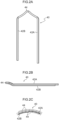
- the segment coil 40 is a structure produced by a rectangular wire, which is formed of copper or the like and covered by an insulating film, being shaped into a U-shape, and is structured by the pair of leg portions 42A, 42B that extend parallel to one another, and a bent portion (turn portion) 44 that connects one end portions of the pair of leg portions 42A, 42B together.
- the leg portion 42A at one side in the peripheral direction is formed to be slightly longer in the axial direction than the leg portion 42B at the another side in the peripheral direction.
- the insulating film is removed at the distal end portions of the respective leg portions 42A, 42B.
- the central portion of the bent portion 44 is bent in the shape of a crank such that one end side of the bent portion 44 is disposed so as to be offset in the radial direction with respect to the another end side of the bent portion 44.
- the segment coil 40 is structured such that the positional relationship in the radial direction between the leg portion 42A and the leg portion 42B is changed due to this bent portion 44 being formed. Due thereto, the plural segment coils 40 are layered in the radial direction as illustrated by the two-dot chain lines in Fig. 2C .
- the both leg portions 42A, 42B are respectively inserted into the respective slots 16 of the stator core 14 from an axial direction one side, and the segment coils 40 are superposed in plural layers in the radial direction of the stator coil 14 and are arrayed in annular forms.
- one layer is formed by the segment coils 40 being successively inserted into the slots 16 one-by-one along the peripheral direction, once around the periphery.
- three layers 46A, 46B, 46C of the segment coils 40 are formed.
- a stopper portion 18 which prevents the segment coil 40 from falling out of the slot 16, is formed at the radial direction inner side end portion of each slot 16.
- a method can be employed in which, by setting the numerous segment coils 40 in an annular arraying jig, an assembly of the segment coils 40 that are arrayed in an annular form is formed, and each assembly is inserted one-by-one into the respective slots 16 of the stator core 14.
- a method may be employed in which the segment coils 40 are inserted one-by-one into the respective slots 16 of the stator core 14.
- the numerous segment coils 40 are only inserted midway into the respective slots 16 of the stator core 14. Therefore, after the numerous segment coils 40 are inserted into the respective slots 16 of the stator core 14, a push-in step of pushing the numerous segment coils 40 further into the stator core 14 is carried out.
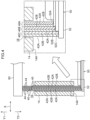
- the push-in step of the numerous segment coils 40 is carried out by using a first jig 50 and a second jig 60 illustrated in Fig. 4 . Due to this push-in step, the numerous segment coils 40 are pushed into the stator core 14 up to set positions.
- this push-in step is carried out, the amounts of projection of the final ends of the leg portions 42A, 42B from an end surface 14A at the axial direction another side of the stator core 14 become longer in a stepwise manner from the layer 46A at the inner side toward the layer 46C at the outer side of the plural layers 46A, 46B, 46C. Note that, in the following explanation, there are cases in which the leg portions 42A, 42B of the segment coils 40 are simply called the "leg portions 42".
- the method moves onto an interlayer interval widening step that is the next step.
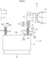
- the interlayer interval widening step as illustrated in Fig. 5 , the stator 10 after the push-in step is placed on an unillustrated turntable in a posture in which the final ends of the leg portions 42 of the plural segment coils 40 are facing upward. Note that the bent portions 44 of the plural segment coils 40 are illustrated schematically in Fig. 5 .
- the aforementioned turntable structures a portion of an interlayer interval widening device 70 illustrated in Fig. 5 .
- the intervals in the radial direction between the final ends of the leg portions 42 of the respective layers 46A, 46B, 46C are widened by using the above-described interlayer interval widening device 70.
- This widening of the intervals is, as an example, carried out successively per one slot 16. Due to this widening of the intervals, the plural (here, six) leg portions 42 that are inserted in the same slot 16 are moved apart from one another per pair 42A, 42B of each of the layers 46A, 46B, 46C.
- insulating paper (not illustrated in Fig. 1 , Fig. 3 and Fig. 4 ) for insulating the leg portions 42 of the segment coils 40 from the stator core 14.
- the above-described interlayer interval widening device 70 is structured to include a robot manipulator 72, a tool 74, a clamp 78 and a pusher 84.
- the robot manipulator 72 structures, for example, the main body portion of a vertical articulated robot of six axes, and the operations thereof are controlled by an unillustrated controller. Note that, in Fig. 5 , theta indicates the angle of rotation around the fifth axis of the robot manipulator 72.
- the tool 74 is an end effector that is mounted to the distal end of the robot manipulator 72, and is formed of metal for example.
- This tool 74 has comb teeth 76 that are formed in the shapes of teeth of a comb.
- the comb teeth 76 have plural (here, three) teeth 76A, 76B, 76C that are lined-up at an interval in the axial direction of the sixth axis of the robot manipulator 72.
- the three teeth 76A, 76B, 76C are formed in the shapes of plates whose plate thickness directions are the axial direction of the aforementioned sixth axis and whose length directions are the radial direction of the aforementioned sixth axis, and the distal ends thereof are pointed in the forms of single-edge blades.
- the tool 74 is disposed above the stator 10 in a posture in which the three teeth 76A, 76B, 76C extend downward and the direction in which the three teeth 76A, 76B, 76C are lined-up is the same direction as the radial direction.
- the three teeth 76A, 76B, 76C are in postures in which the surfaces thereof that are inclined in the forms of single-edge blades face the radial direction outer side. Note that it suffices for the tool 74 to have at least one tooth.
- the clamp 78 has an inner radial side coil presser 80 and an outer radial side coil presser 82.
- the inner radial side coil presser 80 and the outer radial side coil presser 82 are, for example, formed in the shapes of plates and of metal.
- the inner radial side coil presser 80 is disposed at the inner side, in the radial direction of the stator core 14, of the roots of the portions, which project-out from the end surface 14A of the stator core 14, of the final ends of the leg portions 42A of the layer 46A at the inner side.
- the outer radial side coil presser 82 is disposed at the outer side, in the radial direction of the stator core 14, of the roots of the portions, which project-out from the end surface 14A of the stator core 14, of the final ends of the leg portions 42B of the layer 46C at the outer side.
- the inner radial side coil presser 80 and the outer radial side coil presser 82 are moved in the radial direction of the stator core 14 by an unillustrated actuator (refer to arrow A and arrow B in Fig. 5 ).
- the roots of the portions, which project-out from the end surface 14A, of the final ends of the leg portions 42 of the respective layers 46A, 46B, 46C can be nipped in the radial direction by the inner radial side coil presser 80 and the outer radial side coil presser 82.
- the pusher 84 is, for example, formed in the shape of a block and of resin, and is disposed at the outer side, in the radial direction of the stator core 14, of the distal end portions of the portions, which project-out from the end surface 14A of the stator core 14, of the final ends of the leg portions 42B of the layer 46C at the outer side.
- the pusher 84 is moved in the radial direction by an unillustrated actuator (refer to arrow C in Fig. 5 ).
- the final ends of the leg portions 42 of the layer 46C at the outer side can be pushed toward the radial direction inner side by this pusher 84.
- the interlayer interval widening device 70 of the above-described structure carries out an interlayer interval widening step due to operations of the above-described robot manipulator 72, turntable, and respective actuators being controlled by an unillustrated controller.
- this interlayer interval widening step first, as illustrated in Fig. 6 , the roots of the portions, which project-out from the end surface 14A of the stator core 14, of the final ends of the leg portions 42 of the respective layers 46A, 46B, 46C are nipped in the radial direction by the clamp 78 (refer to arrow A1 and arrow B 1 in Fig. 6 ).
- leg portions 42 of the respective layers 46A, 46B, 46C are thereby positioned in the radial direction, the insulating paper 48 is protected, the point of origin of the bending of the leg portions 42 of the respective layers 46A, 46B, 46C is generated, and axial direction movement of the leg portions 42 of the respective layers 46A, 46B, 46C is restricted.
- the tool 74 is moved in the axial direction and the radial direction by the robot manipulator 72 (refer to arrow D1, arrow E1 and arrow D2 in Fig. 7 ). Due thereto, as illustrated in Fig. 7 and Fig. 8 , the distal ends of the comb teeth 76 of the tool 74 are inserted between the final ends of the leg portions 42 of respective layers 46A, 46B, 46C. Specifically, the distal end of the tooth 76B of the comb teeth 76 is inserted between the layer 46A and the layer 46B, and the distal end of the tooth 76C of the comb teeth 76 is inserted between the layer 46B and the layer 46C.
- the teeth 76B, 76C of the comb teeth 76 are inserted between the final ends of the leg portions 42 of respective layers 46A, 46B, 46C, from the axial direction another side (the upper side) toward the axial direction one side (the lower side).
- the tool 74 is tilted around an axis (here, the fifth axis of the robot manipulator 72) that is orthogonal to the direction in which the comb teeth 76 are lined-up (the radial direction) and the direction of insertion of the comb teeth 76.
- the tool 74 is tilted such that the respective distal ends of the teeth 76A, 76B, 76C of the comb teeth 76 are displaced toward the axial direction one side and the radial direction outer side. Due thereto, as illustrated in Fig. 9 and Fig. 10 , the respective distal ends of the teeth 76A, 76B, 76C of the comb teeth 76 are made to not contact the insulating films of the final ends of the leg portions 42.
- the tool 74 is moved toward the axial direction one side as shown by arrow D3 in Fig. 9 .
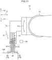
- the tool 74 is rotated around the fifth axis of the robot manipulator 72 in a state in which the tool 74 has been moved toward the axial direction one side. Due thereto, for example, in the midst of the tool 74 being moved toward the axial direction one side as illustrated by arrow G in Fig. 11 , the tool 74 is rotated around the fifth axis of the robot manipulator 72 as illustrated by arrow F2, and the comb teeth 76 of the tool 74 are set vertical.
- the comb teeth 76 may be inserted between the final ends of the leg portions 42 of the respective layers 46A, 46B, 46C while the tool 74 is being tilted around the fifth axis of the robot manipulator 72. Further, in the state in which the comb teeth 76 have been completely inserted between the final ends of the leg portions 42 of the respective layers 46A, 46B, 46C, the tool 74 may be in a tilted state or may not be in a tilted state.
- the comb teeth 76 When the comb teeth 76 have been completely inserted between the final ends of the leg portions 42 of the respective layers 46A, 46B, 46C, due to the tool 74 being moved by the robot manipulator 72, the final ends of the leg portions 42 of the respective layers 46A, 46B, 46C are bent in predetermined shapes (substantial crank shapes). Thereafter, the tool 74 is raised by the robot manipulator 72, and the comb teeth 76 are pulled-out from between the final ends of the leg portions 42 of the respective layers 46A, 46B, 46C.
- the interlayer interval widening step is thereby completed.
- the present embodiment is structured such that the process of widening the intervals between the layers is carried out per one slot 16, but the present disclosure is not limited to this.
- the process of widening the intervals between the layers may be carried out per plural slots 16 by providing a plurality of the structural members of the interlayer interval widening device 70 such as the robot manipulator 72 and the like.
- the stator 10 that has the stator core 14 in which the plural slots 16 are formed, and the plural segment coils 40 whose both leg portions 42A, 42B are inserted in the respective slots 16 of the stator core 14, and that are superposed in the plural layers 46A, 46B, 46C in the radial direction of the stator core 14, and that are arrayed in annular forms.
- the both leg portions 42A, 42B of the plural segment coils 40 are respectively inserted into the respective slots 16 of the stator core 14 from the axial direction one side of the stator core 14.
- the comb teeth 76 are inserted in, from the axial direction another side toward the axial direction one side, between the final ends of the leg portions 42 of the respective layers 46A, 46B, 46C. Due thereto, the intervals between the final ends of the leg portions 42 of the respective layers 46A, 46B, 46C are widened.
- the distal ends of the comb teeth 76 are made to not contact the insulating films of the final ends of the leg portions 42. Due thereto, the insulating films at the final ends of the leg portions 42 can be prevented from being damaged.
- the amounts of projection of the final ends of the leg portions 42 from the end surface 14A at the axial direction another side of the stator core 14 are set so as to become longer in a stepwise manner from the layer 46A at the inner side toward the layer 46C at the outer side of the above-described plural layers 46A, 46B, 46C. Due thereto, it is easy to widen the intervals between the final ends of the leg portions 42 of the respective layers 46A, 46B, 46C. Further, the twisting processing in a twisting step thereafter is easy.
- the tool 74 is rotated around an axis that is orthogonal to the direction in which the comb teeth 76 are lined-up and the direction of insertion of the comb teeth 76, in a state in which the tool 74 has been moved toward the axial direction one side of the stator core 14. Due thereto, the tilting of the comb teeth 76 can be adjusted in accordance with the positions of the leg portions 42 that are displaced in the radial direction of the stator core 14 due to the insertion of the comb teeth 76.
- the comb teeth 76 of the tool 74 are moved toward the axial direction one side of the stator core 14 (refer to arrow E3 and arrow D6 in Fig. 16 ) in the state in which the intervals between the final ends of the leg portions 42 of the respective layers 46A, 46B, 46C have been widened toward the outer side in the radial direction. Therefore, the sliding resistance between the leg portions 42 and the comb teeth 76 becomes large. As a result, the load on the robot manipulator 72 increases, and the positions of the segment coils 40 are inadvertently offset toward the axial direction one side (refer to arrows G in Fig. 17 ).
- the distal ends of the comb teeth 76 are made to not contact the final ends of the leg portions 42. Therefore, not only can damage to the insulating films of the final ends of the leg portions 42 be prevented, but also, an increase in the load of the robot manipulator 72 and inadvertent positional offset of the segment coils 40 can be avoided. Moreover, because it is possible to use the tool 74 at which the distal ends of the comb teeth 76 are pointed, the insertion of the comb teeth 76 into between the final ends of the leg portions 42 of the respective layers 46A, 46B, 46C is easy.
Landscapes
- Engineering & Computer Science (AREA)
- Manufacturing & Machinery (AREA)
- Power Engineering (AREA)
- Manufacture Of Motors, Generators (AREA)
Abstract
Description
- The present disclosure relates to a method of manufacturing an armature.
- International Patent Publication No.
2019/093515 discloses a method of processing segment coils that carries out twisting processing on the final ends of the leg portions of segment coils that project-out from an end surface of a core of an armature of a rotating electric machine. The final ends of the plural segment coil leg portions that have been subjected to the twisting processing are electrically joined together by welding or the like. In this processing method, the plural segment coils are superposed in plural layers in the radial direction of the core and are arrayed in annular forms. Then, twisting processing is carried out on the final ends of the segment coil leg portions that project-out from an end surface of the core. A disentangling process (a process for widening the intervals between the layers) is carried out before the twisting processing. In this disentangling process, a disentangling member having an interlayer interval widening member is moved in the radial direction and the axial direction of the core, and the final ends of the segment coil leg portions of the respective layers are separated, and the intervals between the final ends of the segment coil leg portions of the respective layers are thereby widened. Due thereto, the complexity and bother of aligning the final ends of the segment coil leg portions with respect to a twisting tool are reduced, and an improvement in the work efficiency in the twisting step is devised. - In the above-described prior art, at the time when the disentangling member is moved in the radial direction and the axial direction of the core, the disentangling member slidingly contacts the final ends of the segment coil leg portions, and there is the possibility that the insulating films at the final ends will be damaged.
- In view of the above-described circumstances, an object of the present disclosure is to provide a method of manufacturing an armature that can prevent insulating films at the final ends of segment coil leg portions from being damaged at the time when the interlayer intervals are widened.
- A method of manufacturing an armature of a first aspect is a method of manufacturing an armature having a core in which a plurality of slots are formed, and a plurality of segment coils having both leg portions inserted in respective slots of the core and that are superposed in a plurality of layers in a radial direction of the core and are arrayed in annular forms, the method comprising: inserting the both leg portions of each of the plurality of segment coils into the respective slots of the core from an axial direction one side of the core; by moving a tool that has at least one tooth by a robot manipulator, inserting the at least one tooth between final ends of the respective layers from an axial direction other side toward the axial direction one side; and at a time of inserting the at least one tooth between the final ends, by tilting the tool around an axis that is orthogonal to a direction of insertion of the at least one tooth and to the radial direction, making a distal end of the at least one tooth not contact insulating films that are at the final ends.
- In the method of manufacturing an armature of the first aspect, the armature is manufactured that has the core in which plural slots are formed, and the plural segment coils whose both leg portions are inserted in the respective slots of the core and that are superposed in plural layers in a radial direction of the core and are arrayed in annular forms. In this manufacturing method, both leg portions of each of the plural segment coils are inserted into the respective slots of the core from an axial direction one side of the core. Then, due to a tool that has at least one tooth being moved by a robot manipulator, the at least one tooth is inserted between the final ends of the segment coil leg portions of the respective layers from the axial direction another side toward the axial direction one side. Due thereto, the intervals between the final ends of the segment coil leg portions of the respective layers are widened. At the above-described time of inserting the at least one tooth, due to the tool being tilted around an axis that is orthogonal to the direction of insertion of the at least one tooth and to the radial direction, the distal end of the at least one tooth is made to not contact the insulating films that are at the final ends of the segment coil leg portions. Due thereto, the insulating films at the final ends of the segment coil leg portions can be prevented from being damaged.
- In a method of manufacturing an armature of a second aspect, in the first aspect, at the time of inserting the at least one tooth, the tool is rotated around the axis while being moved toward the axial direction one side.
- In the method of manufacturing an armature of the second aspect, at the time of inserting the at least one tooth of the tool between the final ends of the segment coil leg portions of the respective layers, the tool is rotated around an axis, which is orthogonal to the direction of insertion of the at least one tooth and to the radial direction of the core, in a state in which the tool has been moved toward the axial direction one side of the core. Due thereto, the tilting of the at least one tooth can be adjusted in accordance with the positions of the segment coil leg portions that are displaced in the radial direction of the core due to the insertion of the at least one tooth.
- As described above, in the method of manufacturing an armature relating to the present disclosure, the insulating films at the final ends of the segment coil leg portions can be prevented from being damaged at the time when the interlayer intervals are widened.
-
-
Fig. 1 is a perspective view illustrating a state in the midst of manufacturing a stator by a method of manufacturing an armature relating to an embodiment. -
Fig. 2A is a front view illustrating a segment coil. -
Fig. 2B is a side view illustrating the segment coil. -
Fig. 2C is a top view illustrating the segment coil. -
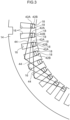
Fig. 3 is a plan view for explaining a method of inserting segment coil leg portions into respective slots of a stator core. -
Fig. 4 is a cross-sectional view for explaining a push-in step of segment coils. -
Fig. 5 is a side view illustrating peripheral structures, including main portions of an interlayer interval widening device. -
Fig. 6 is a side view illustrating a state in which the segment coil leg portions that are superposed in plural layers are nipped by a clamp. -
Fig. 7 is a side view illustrating a state in which distal ends of comb teeth of a tool are inserted between final ends of the segment coil leg portions of the respective layers. -
Fig. 8 is an enlarged side view in which a portion ofFig. 7 is enlarged. -
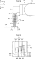
Fig. 9 is a side view illustrating a state in which the tool is tilted at the time when the comb teeth of the tool are inserted between the final ends of the segment coil leg portions of the respective layers. -
Fig. 10 is an enlarged side view in which a portion ofFig. 9 is enlarged. -
Fig. 11 is a side view illustrating a state in which the comb teeth of the tool are set vertically, in the midst of the comb teeth being inserted between the final ends of the segment coil leg portions of the respective layers. -
Fig. 12 is a side view illustrating a state in which, in a first comparative example, the comb teeth are being inserted between the final ends of the segment coil leg portions of the respective layers in a state in which the tool is not tilted. -
Fig. 13 is an enlarged side view in which a portion ofFig. 12 is enlarged. -
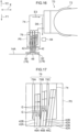
Fig. 14 is a side view illustrating a state in which, in a second comparative example, at the time when the comb teeth of the tool are inserted between the final ends of the segment coil leg portions of the respective layers, the tool is moved toward the radial direction outer side of the stator core and the interlayer intervals are enlarged. -
Fig. 15 is an enlarged side view in which a portion ofFig. 14 is enlarged. -
Fig. 16 is a side view illustrating a state in which, in the second comparative example, in a state in which the intervals between the final ends of the segment coil leg portions of the respective layers have been enlarged, the comb teeth of the tool are being moved toward an axial direction one side of the stator core. -
Fig. 17 is an enlarged side view in which a portion ofFig. 16 is enlarged. - A method of manufacturing an armature relating to an embodiment of the present disclosure is described hereinafter with reference to
Fig. 1 through Fig. 11 . Note that, in the respective drawings, there are cases in which some of the reference numerals are omitted in order to make the drawings easier to understand. A state in the midst of manufacturing astator 10, which is manufactured by the method of manufacturing an armature relating to the present embodiment, is illustrated in a perspective view inFig. 1 . This stator 10 (stator; armature) has astator core 14 in whichnumerous slots 16 are formed, and numerous segment coils (rectangular wire coils) 40 whose bothleg portions respective slots 16 of thestator core 14 and that are superposed in plural layers in the radial direction of thestator core 14 and are arrayed in annular forms. - The
stator core 14 corresponds to the "core" in the present disclosure. Thisstator core 14 is formed in the shape of a cylindrical tube by numerous electromagnetic steel plates being layered. Thenumerous slots 16 are formed in the inner peripheral portion of thestator core 14. At thenumerous slots 16, the both sides in the axial direction of thestator core 14 and the inner sides in the radial direction are open. Note that, inFig. 4 through Fig. 7 and inFig. 9 , arrow Yl, arrow Y2 and arrow X indicate an axial direction one side, an axial direction another side, and the radial direction of thestator core 14, respectively. Hereinafter, there are cases in which the axial direction of thestator core 14 is simply called the "axial direction", the radial direction of thestator core 14 is simply called the "radial direction", and the peripheral direction of thestator core 14 is simply called the "peripheral direction". - As illustrated in
Fig. 2A through Fig. 2C , thesegment coil 40 is a structure produced by a rectangular wire, which is formed of copper or the like and covered by an insulating film, being shaped into a U-shape, and is structured by the pair ofleg portions leg portions leg portion 42A at one side in the peripheral direction is formed to be slightly longer in the axial direction than theleg portion 42B at the another side in the peripheral direction. Further, the insulating film is removed at the distal end portions of therespective leg portions - As illustrated in
Fig. 2C , the central portion of thebent portion 44 is bent in the shape of a crank such that one end side of thebent portion 44 is disposed so as to be offset in the radial direction with respect to the another end side of thebent portion 44. Thesegment coil 40 is structured such that the positional relationship in the radial direction between theleg portion 42A and theleg portion 42B is changed due to thisbent portion 44 being formed. Due thereto, the plural segment coils 40 are layered in the radial direction as illustrated by the two-dot chain lines inFig. 2C . - As illustrated in
Fig. 1 , at the numerous segment coils 40, the bothleg portions respective slots 16 of thestator core 14 from an axial direction one side, and the segment coils 40 are superposed in plural layers in the radial direction of thestator coil 14 and are arrayed in annular forms. As illustrated inFig. 3 , one layer is formed by the segment coils 40 being successively inserted into theslots 16 one-by-one along the peripheral direction, once around the periphery. In the present embodiment, as illustrated inFig. 4 , threelayers Fig. 3 ), which prevents thesegment coil 40 from falling out of theslot 16, is formed at the radial direction inner side end portion of eachslot 16. - As illustrated in
Fig. 4 , in the present embodiment, the axial direction lengths of the bothleg portions layer 46A at the inner side toward thelayer 46C at the outer side of the threelayers Fig. 3 andFig. 4 , within each of theslots 16, at each of therespective layers leg portion 42A at one side of one of the segment coils 40 is superposed on the radial direction outer side of theleg portion 42B at the another side of another one of the segment coils 40. - Note that, in the inserting of the numerous segment coils 40 into the
stator core 14, for example, a method can be employed in which, by setting the numerous segment coils 40 in an annular arraying jig, an assembly of the segment coils 40 that are arrayed in an annular form is formed, and each assembly is inserted one-by-one into therespective slots 16 of thestator core 14. Or, for example, a method may be employed in which the segment coils 40 are inserted one-by-one into therespective slots 16 of thestator core 14. When either of these methods is employed, the numerous segment coils 40 are only inserted midway into therespective slots 16 of thestator core 14. Therefore, after the numerous segment coils 40 are inserted into therespective slots 16 of thestator core 14, a push-in step of pushing the numerous segment coils 40 further into thestator core 14 is carried out. - In the present embodiment, the push-in step of the numerous segment coils 40 is carried out by using a
first jig 50 and asecond jig 60 illustrated inFig. 4 . Due to this push-in step, the numerous segment coils 40 are pushed into thestator core 14 up to set positions. When this push-in step is carried out, the amounts of projection of the final ends of theleg portions end surface 14A at the axial direction another side of thestator core 14 become longer in a stepwise manner from thelayer 46A at the inner side toward thelayer 46C at the outer side of theplural layers leg portions leg portions 42". - When the above-described push-in step is completed, the method moves onto an interlayer interval widening step that is the next step. In the interlayer interval widening step, as illustrated in
Fig. 5 , thestator 10 after the push-in step is placed on an unillustrated turntable in a posture in which the final ends of theleg portions 42 of the plural segment coils 40 are facing upward. Note that thebent portions 44 of the plural segment coils 40 are illustrated schematically inFig. 5 . The aforementioned turntable structures a portion of an interlayerinterval widening device 70 illustrated inFig. 5 . - In the interlayer interval widening step, the intervals in the radial direction between the final ends of the
leg portions 42 of therespective layers interval widening device 70. This widening of the intervals is, as an example, carried out successively per oneslot 16. Due to this widening of the intervals, the plural (here, six)leg portions 42 that are inserted in thesame slot 16 are moved apart from one another perpair layers leg portions 42 with respect to the twisting tool is easy, and the work efficiency in the twisting step improves. Note that, inFig. 5 , 48 is an insulating paper (not illustrated inFig. 1 ,Fig. 3 andFig. 4 ) for insulating theleg portions 42 of the segment coils 40 from thestator core 14. - The above-described interlayer
interval widening device 70 is structured to include arobot manipulator 72, atool 74, aclamp 78 and apusher 84. Therobot manipulator 72 structures, for example, the main body portion of a vertical articulated robot of six axes, and the operations thereof are controlled by an unillustrated controller. Note that, inFig. 5 , theta indicates the angle of rotation around the fifth axis of therobot manipulator 72. - The
tool 74 is an end effector that is mounted to the distal end of therobot manipulator 72, and is formed of metal for example. Thistool 74 hascomb teeth 76 that are formed in the shapes of teeth of a comb. Thecomb teeth 76 have plural (here, three)teeth robot manipulator 72. The threeteeth tool 74 is disposed above thestator 10 in a posture in which the threeteeth teeth teeth tool 74 to have at least one tooth. - The
clamp 78 has an inner radialside coil presser 80 and an outer radialside coil presser 82. The inner radialside coil presser 80 and the outer radialside coil presser 82 are, for example, formed in the shapes of plates and of metal. The inner radialside coil presser 80 is disposed at the inner side, in the radial direction of thestator core 14, of the roots of the portions, which project-out from theend surface 14A of thestator core 14, of the final ends of theleg portions 42A of thelayer 46A at the inner side. The outer radialside coil presser 82 is disposed at the outer side, in the radial direction of thestator core 14, of the roots of the portions, which project-out from theend surface 14A of thestator core 14, of the final ends of theleg portions 42B of thelayer 46C at the outer side. The inner radialside coil presser 80 and the outer radialside coil presser 82 are moved in the radial direction of thestator core 14 by an unillustrated actuator (refer to arrow A and arrow B inFig. 5 ). The roots of the portions, which project-out from theend surface 14A, of the final ends of theleg portions 42 of therespective layers side coil presser 80 and the outer radialside coil presser 82. - The
pusher 84 is, for example, formed in the shape of a block and of resin, and is disposed at the outer side, in the radial direction of thestator core 14, of the distal end portions of the portions, which project-out from theend surface 14A of thestator core 14, of the final ends of theleg portions 42B of thelayer 46C at the outer side. Thepusher 84 is moved in the radial direction by an unillustrated actuator (refer to arrow C inFig. 5 ). The final ends of theleg portions 42 of thelayer 46C at the outer side can be pushed toward the radial direction inner side by thispusher 84. - The interlayer
interval widening device 70 of the above-described structure carries out an interlayer interval widening step due to operations of the above-describedrobot manipulator 72, turntable, and respective actuators being controlled by an unillustrated controller. In this interlayer interval widening step, first, as illustrated inFig. 6 , the roots of the portions, which project-out from theend surface 14A of thestator core 14, of the final ends of theleg portions 42 of therespective layers Fig. 6 ). The final ends of theleg portions 42 of therespective layers paper 48 is protected, the point of origin of the bending of theleg portions 42 of therespective layers leg portions 42 of therespective layers - Next, as illustrated in
Fig. 7 , thetool 74 is moved in the axial direction and the radial direction by the robot manipulator 72 (refer to arrow D1, arrow E1 and arrow D2 inFig. 7 ). Due thereto, as illustrated inFig. 7 and Fig. 8 , the distal ends of thecomb teeth 76 of thetool 74 are inserted between the final ends of theleg portions 42 ofrespective layers tooth 76B of thecomb teeth 76 is inserted between thelayer 46A and thelayer 46B, and the distal end of thetooth 76C of thecomb teeth 76 is inserted between thelayer 46B and thelayer 46C. - Next, due to the
tool 74 being moved toward the axial direction one side (the lower side) by therobot manipulator 72, theteeth comb teeth 76 are inserted between the final ends of theleg portions 42 ofrespective layers tool 74 is tilted around an axis (here, the fifth axis of the robot manipulator 72) that is orthogonal to the direction in which thecomb teeth 76 are lined-up (the radial direction) and the direction of insertion of thecomb teeth 76. At this time, thetool 74 is tilted such that the respective distal ends of theteeth comb teeth 76 are displaced toward the axial direction one side and the radial direction outer side. Due thereto, as illustrated inFig. 9 and Fig. 10 , the respective distal ends of theteeth comb teeth 76 are made to not contact the insulating films of the final ends of theleg portions 42. - In the present embodiment, as an example, after the
tool 74 is tilted around the fifth axis of therobot manipulator 72 as shown by arrow F1 inFig. 9 , thetool 74 is moved toward the axial direction one side as shown by arrow D3 inFig. 9 . Further, in the present embodiment, at the time when thecomb teeth 76 are inserted between the final ends of theleg portions 42 ofrespective layers tool 74 is rotated around the fifth axis of therobot manipulator 72 in a state in which thetool 74 has been moved toward the axial direction one side. Due thereto, for example, in the midst of thetool 74 being moved toward the axial direction one side as illustrated by arrow G inFig. 11 , thetool 74 is rotated around the fifth axis of therobot manipulator 72 as illustrated by arrow F2, and thecomb teeth 76 of thetool 74 are set vertical. - Note that the
comb teeth 76 may be inserted between the final ends of theleg portions 42 of therespective layers tool 74 is being tilted around the fifth axis of therobot manipulator 72. Further, in the state in which thecomb teeth 76 have been completely inserted between the final ends of theleg portions 42 of therespective layers tool 74 may be in a tilted state or may not be in a tilted state. - When the
comb teeth 76 have been completely inserted between the final ends of theleg portions 42 of therespective layers tool 74 being moved by therobot manipulator 72, the final ends of theleg portions 42 of therespective layers tool 74 is raised by therobot manipulator 72, and thecomb teeth 76 are pulled-out from between the final ends of theleg portions 42 of therespective layers slot 16, but the present disclosure is not limited to this. The process of widening the intervals between the layers may be carried out perplural slots 16 by providing a plurality of the structural members of the interlayerinterval widening device 70 such as therobot manipulator 72 and the like. - In the method of manufacturing a stator relating to the present embodiment, there is manufactured the
stator 10 that has thestator core 14 in which theplural slots 16 are formed, and the plural segment coils 40 whose bothleg portions respective slots 16 of thestator core 14, and that are superposed in theplural layers stator core 14, and that are arrayed in annular forms. In this manufacturing method, the bothleg portions respective slots 16 of thestator core 14 from the axial direction one side of thestator core 14. - Then, due to the
tool 74 that has thecomb teeth 76 being moved by therobot manipulator 72, thecomb teeth 76 are inserted in, from the axial direction another side toward the axial direction one side, between the final ends of theleg portions 42 of therespective layers leg portions 42 of therespective layers comb teeth 76, due to thetool 74 being tilted around an axis that is orthogonal to the direction in which thecomb teeth 76 are lined-up and the direction of insertion of thecomb teeth 76, the distal ends of thecomb teeth 76 are made to not contact the insulating films of the final ends of theleg portions 42. Due thereto, the insulating films at the final ends of theleg portions 42 can be prevented from being damaged. - Further, in the present embodiment, the amounts of projection of the final ends of the
leg portions 42 from theend surface 14A at the axial direction another side of thestator core 14 are set so as to become longer in a stepwise manner from thelayer 46A at the inner side toward thelayer 46C at the outer side of the above-describedplural layers leg portions 42 of therespective layers - Further, in the present embodiment, at the time when the
comb teeth 76 of thetool 74 are inserted between the final ends of theleg portions 42 of therespective layers tool 74 is rotated around an axis that is orthogonal to the direction in which thecomb teeth 76 are lined-up and the direction of insertion of thecomb teeth 76, in a state in which thetool 74 has been moved toward the axial direction one side of thestator core 14. Due thereto, the tilting of thecomb teeth 76 can be adjusted in accordance with the positions of theleg portions 42 that are displaced in the radial direction of thestator core 14 due to the insertion of thecomb teeth 76. - Effects of the present embodiment are additionally described hereinafter with reference to the comparative examples illustrated in
Fig. 12 through Fig. 17 . In a first comparative example illustrated inFig. 12 and Fig. 13 , thecomb teeth 76 are inserted between the final ends of theleg portions 42 of therespective layers Fig. 12 ) in a state in which thetool 74 is not tilted. In this first comparative example, as illustrated inFig. 13 , the insulating films at the final ends of theleg portions 42 are damaged due to the distal ends of thecomb teeth 76 slidingly contacting the side surfaces of the final ends of theleg portions 42. - On the other hand, in a second comparative example illustrated in
Fig. 14 , at the time when thecomb teeth 76 of thetool 74 are inserted between the final ends of theleg portions 42 of therespective layers tool 74 is moved toward the radial direction outer side of the stator core 14 (refer to arrow E2 and arrow D5 inFig. 14 ) in the state in which the respective distal end sides of theteeth comb teeth 76 contact the final ends of theleg portions 42 of therespective layers leg portions 42 of therespective layers Fig. 15 , in the initial stage of the inserting of thecomb teeth 76, it can be made such that the distal ends of thecomb teeth 76 do not contact the final ends of theleg portions 42. - However, in this second comparative example, the
comb teeth 76 of thetool 74 are moved toward the axial direction one side of the stator core 14 (refer to arrow E3 and arrow D6 inFig. 16 ) in the state in which the intervals between the final ends of theleg portions 42 of therespective layers leg portions 42 and thecomb teeth 76 becomes large. As a result, the load on therobot manipulator 72 increases, and the positions of the segment coils 40 are inadvertently offset toward the axial direction one side (refer to arrows G inFig. 17 ). - In contrast, in the present embodiment, as described above, due to the tilting of the
tool 74, the distal ends of thecomb teeth 76 are made to not contact the final ends of theleg portions 42. Therefore, not only can damage to the insulating films of the final ends of theleg portions 42 be prevented, but also, an increase in the load of therobot manipulator 72 and inadvertent positional offset of the segment coils 40 can be avoided. Moreover, because it is possible to use thetool 74 at which the distal ends of thecomb teeth 76 are pointed, the insertion of thecomb teeth 76 into between the final ends of theleg portions 42 of therespective layers - Note that the above embodiment describes a case in which a stator is manufactured, but the present disclosure can be applied also to manufacture of a rotor.
- In addition, the present disclosure can be implemented by being modified in various ways within a scope that does not depart from the gist thereof. Further, the scope of the right of the present disclosure is, of course, not limited by the above-described embodiment.
- The disclosure of
Japanese Patent Application No. 2022-009724 filed on January 25, 2022
Claims (2)
- A method of manufacturing an armature having a core in which a plurality of slots are formed, and a plurality of segment coils having both leg portions inserted in respective slots of the core and that are superposed in a plurality of layers in a radial direction of the core and are arrayed in annular forms, the method comprising:inserting the both leg portions of each of the plurality of segment coils into the respective slots of the core from an axial direction one side of the core;by moving a tool that has at least one tooth by a robot manipulator, inserting the at least one tooth between final ends of the leg portions of the respective layers from an axial direction other side toward the axial direction one side; andat a time of inserting the at least one tooth between the final ends, by tilting the tool around an axis that is orthogonal to a direction of insertion of the at least one tooth and to the radial direction, making a distal end of the at least one tooth not contact insulating films that are at the final ends.
- The method of manufacturing an armature of Claim 1, wherein, at the time of inserting the at least one tooth, the tool is rotated around the axis while being moved toward the axial direction one side.
Applications Claiming Priority (2)
| Application Number | Priority Date | Filing Date | Title |
|---|---|---|---|
| JP2022009724 | 2022-01-25 | ||
| PCT/JP2022/042932 WO2023145209A1 (en) | 2022-01-25 | 2022-11-18 | Armature manufacturing method |
Publications (2)
| Publication Number | Publication Date |
|---|---|
| EP4472041A1 true EP4472041A1 (en) | 2024-12-04 |
| EP4472041A4 EP4472041A4 (en) | 2025-05-07 |
Family
ID=86142502
Family Applications (1)
| Application Number | Title | Priority Date | Filing Date |
|---|---|---|---|
| EP22924061.9A Pending EP4472041A4 (en) | 2022-01-25 | 2022-11-18 | ANCHOR MANUFACTURING PROCESS |
Country Status (5)
| Country | Link |
|---|---|
| US (1) | US20250239925A1 (en) |
| EP (1) | EP4472041A4 (en) |
| JP (1) | JP7266158B1 (en) |
| CN (1) | CN118575402A (en) |
| MX (1) | MX2024009109A (en) |
Family Cites Families (8)
| Publication number | Priority date | Publication date | Assignee | Title |
|---|---|---|---|---|
| JP5904103B2 (en) * | 2012-11-22 | 2016-04-13 | トヨタ自動車株式会社 | Stator manufacturing method, stator, and manufacturing apparatus thereof |
| DE102015217922A1 (en) * | 2015-09-18 | 2017-03-23 | Continental Automotive Gmbh | Method and two-part tool assembly for manufacturing a stator for an electric machine |
| JP6299723B2 (en) * | 2015-10-23 | 2018-03-28 | トヨタ自動車株式会社 | Stator coil forming method |
| JP6801369B2 (en) * | 2016-10-28 | 2020-12-16 | トヨタ自動車株式会社 | How to twist the coil end |
| JP6673180B2 (en) * | 2016-12-16 | 2020-03-25 | トヨタ自動車株式会社 | Stator manufacturing equipment |
| JP6936112B2 (en) * | 2017-10-26 | 2021-09-15 | トヨタ自動車株式会社 | Coil end molding method |
| JP6943753B2 (en) * | 2017-12-22 | 2021-10-06 | トヨタ自動車株式会社 | Coil bending device |
| JP6962275B2 (en) * | 2018-05-30 | 2021-11-05 | トヨタ自動車株式会社 | Motor stator and its manufacturing method |
-
2022
- 2022-11-18 US US18/730,280 patent/US20250239925A1/en active Pending
- 2022-11-18 MX MX2024009109A patent/MX2024009109A/en unknown
- 2022-11-18 CN CN202280089358.9A patent/CN118575402A/en active Pending
- 2022-11-18 EP EP22924061.9A patent/EP4472041A4/en active Pending
- 2022-11-18 JP JP2023514942A patent/JP7266158B1/en active Active
Also Published As
| Publication number | Publication date |
|---|---|
| EP4472041A4 (en) | 2025-05-07 |
| JP7266158B1 (en) | 2023-04-27 |
| JPWO2023145209A1 (en) | 2023-08-03 |
| CN118575402A (en) | 2024-08-30 |
| US20250239925A1 (en) | 2025-07-24 |
| MX2024009109A (en) | 2024-07-30 |
Similar Documents
| Publication | Publication Date | Title |
|---|---|---|
| US8726493B2 (en) | Clamping system of special conductors for a stator or rotor bar winding for an electric machine | |
| EP4472042A1 (en) | Armature manufacturing method | |
| JP5637301B2 (en) | Stator and stator manufacturing method | |
| EP3868006A1 (en) | Apparatus and method for manufacturing a stator | |
| US10778072B2 (en) | Electrical conductor bending method and apparatus | |
| US11196313B2 (en) | Stator manufacturing method | |
| CN110556930A (en) | Stator of electric motor and method of manufacturing the same | |
| JP5942236B1 (en) | Coil unit array device | |
| CN110918822A (en) | Terminal bending device, terminal bending method, and method for manufacturing coil component | |
| US20250239925A1 (en) | Method of manufacturing armature | |
| US10951096B2 (en) | Method and apparatus for producing rotating electric machine stator | |
| WO2023145209A1 (en) | Armature manufacturing method | |
| WO2023145211A1 (en) | Production method for armature | |
| EP4472043A1 (en) | Production method for armature | |
| US20250309737A1 (en) | Method for manufacturing stator and device for manufacturing stator | |
| US11858029B2 (en) | Method for processing round metallic wire, round metallic wire processing apparatus and method for manufacturing power distribution component | |
| JP7643385B2 (en) | Lead shaping method and device | |
| JP2024047192A (en) | Stator manufacturing method and coil twisting device | |
| US20240413694A1 (en) | Electric machine with a connection ring assembly, and method for connecting a connection ring assembly to a conductor element | |
| JP7384011B2 (en) | Coating stripping method and coating stripping device | |
| JP2025089938A (en) | Stator manufacturing equipment | |
| CN118449339A (en) | Method and positioning device for producing plug windings of an electric machine | |
| WO2024069694A1 (en) | Stator of dynamo-electric machine and manufacturing method therefor | |
| US20230387765A1 (en) | Method for manufacturing stator | |
| JP2024079055A (en) | Winding shaping device and winding shaping method |
Legal Events
| Date | Code | Title | Description |
|---|---|---|---|
| STAA | Information on the status of an ep patent application or granted ep patent |
Free format text: STATUS: THE INTERNATIONAL PUBLICATION HAS BEEN MADE |
|
| PUAI | Public reference made under article 153(3) epc to a published international application that has entered the european phase |
Free format text: ORIGINAL CODE: 0009012 |
|
| STAA | Information on the status of an ep patent application or granted ep patent |
Free format text: STATUS: REQUEST FOR EXAMINATION WAS MADE |
|
| 17P | Request for examination filed |
Effective date: 20240724 |
|
| AK | Designated contracting states |
Kind code of ref document: A1 Designated state(s): AL AT BE BG CH CY CZ DE DK EE ES FI FR GB GR HR HU IE IS IT LI LT LU LV MC ME MK MT NL NO PL PT RO RS SE SI SK SM TR |
|
| REG | Reference to a national code |
Ref country code: DE Ref legal event code: R079 Free format text: PREVIOUS MAIN CLASS: H02K0015040000 Ipc: H02K0015240000 |
|
| DAV | Request for validation of the european patent (deleted) | ||
| DAX | Request for extension of the european patent (deleted) | ||
| A4 | Supplementary search report drawn up and despatched |
Effective date: 20250407 |
|
| RIC1 | Information provided on ipc code assigned before grant |
Ipc: H02K 15/064 20250101ALN20250401BHEP Ipc: H02K 15/24 20250101AFI20250401BHEP |