EP4472040A1 - Electric scooter motor - Google Patents
Electric scooter motor Download PDFInfo
- Publication number
- EP4472040A1 EP4472040A1 EP23175977.0A EP23175977A EP4472040A1 EP 4472040 A1 EP4472040 A1 EP 4472040A1 EP 23175977 A EP23175977 A EP 23175977A EP 4472040 A1 EP4472040 A1 EP 4472040A1
- Authority
- EP
- European Patent Office
- Prior art keywords
- motor
- scooter
- temperature
- temperature sensor
- stator winding
- Prior art date
- Legal status (The legal status is an assumption and is not a legal conclusion. Google has not performed a legal analysis and makes no representation as to the accuracy of the status listed.)
- Pending
Links
Images


Classifications
-
- H—ELECTRICITY
- H02—GENERATION; CONVERSION OR DISTRIBUTION OF ELECTRIC POWER
- H02K—DYNAMO-ELECTRIC MACHINES
- H02K11/00—Structural association of dynamo-electric machines with electric components or with devices for shielding, monitoring or protection
- H02K11/20—Structural association of dynamo-electric machines with electric components or with devices for shielding, monitoring or protection for measuring, monitoring, testing, protecting or switching
- H02K11/25—Devices for sensing temperature, or actuated thereby
-
- B—PERFORMING OPERATIONS; TRANSPORTING
- B60—VEHICLES IN GENERAL
- B60L—PROPULSION OF ELECTRICALLY-PROPELLED VEHICLES; SUPPLYING ELECTRIC POWER FOR AUXILIARY EQUIPMENT OF ELECTRICALLY-PROPELLED VEHICLES; ELECTRODYNAMIC BRAKE SYSTEMS FOR VEHICLES IN GENERAL; MAGNETIC SUSPENSION OR LEVITATION FOR VEHICLES; MONITORING OPERATING VARIABLES OF ELECTRICALLY-PROPELLED VEHICLES; ELECTRIC SAFETY DEVICES FOR ELECTRICALLY-PROPELLED VEHICLES
- B60L3/00—Electric devices on electrically-propelled vehicles for safety purposes; Monitoring operating variables, e.g. speed, deceleration or energy consumption
- B60L3/04—Cutting off the power supply under fault conditions
-
- B—PERFORMING OPERATIONS; TRANSPORTING
- B60—VEHICLES IN GENERAL
- B60L—PROPULSION OF ELECTRICALLY-PROPELLED VEHICLES; SUPPLYING ELECTRIC POWER FOR AUXILIARY EQUIPMENT OF ELECTRICALLY-PROPELLED VEHICLES; ELECTRODYNAMIC BRAKE SYSTEMS FOR VEHICLES IN GENERAL; MAGNETIC SUSPENSION OR LEVITATION FOR VEHICLES; MONITORING OPERATING VARIABLES OF ELECTRICALLY-PROPELLED VEHICLES; ELECTRIC SAFETY DEVICES FOR ELECTRICALLY-PROPELLED VEHICLES
- B60L58/00—Methods or circuit arrangements for monitoring or controlling batteries or fuel cells, specially adapted for electric vehicles
- B60L58/10—Methods or circuit arrangements for monitoring or controlling batteries or fuel cells, specially adapted for electric vehicles for monitoring or controlling batteries
- B60L58/24—Methods or circuit arrangements for monitoring or controlling batteries or fuel cells, specially adapted for electric vehicles for monitoring or controlling batteries for controlling the temperature of batteries
-
- H—ELECTRICITY
- H02—GENERATION; CONVERSION OR DISTRIBUTION OF ELECTRIC POWER
- H02K—DYNAMO-ELECTRIC MACHINES
- H02K7/00—Arrangements for handling mechanical energy structurally associated with dynamo-electric machines, e.g. structural association with mechanical driving motors or auxiliary dynamo-electric machines
- H02K7/18—Structural association of electric generators with mechanical driving motors, e.g. with turbines
- H02K7/1807—Rotary generators
- H02K7/1846—Rotary generators structurally associated with wheels or associated parts
-
- B—PERFORMING OPERATIONS; TRANSPORTING
- B60—VEHICLES IN GENERAL
- B60L—PROPULSION OF ELECTRICALLY-PROPELLED VEHICLES; SUPPLYING ELECTRIC POWER FOR AUXILIARY EQUIPMENT OF ELECTRICALLY-PROPELLED VEHICLES; ELECTRODYNAMIC BRAKE SYSTEMS FOR VEHICLES IN GENERAL; MAGNETIC SUSPENSION OR LEVITATION FOR VEHICLES; MONITORING OPERATING VARIABLES OF ELECTRICALLY-PROPELLED VEHICLES; ELECTRIC SAFETY DEVICES FOR ELECTRICALLY-PROPELLED VEHICLES
- B60L2200/00—Type of vehicles
- B60L2200/24—Personal mobility vehicles
-
- B—PERFORMING OPERATIONS; TRANSPORTING
- B60—VEHICLES IN GENERAL
- B60L—PROPULSION OF ELECTRICALLY-PROPELLED VEHICLES; SUPPLYING ELECTRIC POWER FOR AUXILIARY EQUIPMENT OF ELECTRICALLY-PROPELLED VEHICLES; ELECTRODYNAMIC BRAKE SYSTEMS FOR VEHICLES IN GENERAL; MAGNETIC SUSPENSION OR LEVITATION FOR VEHICLES; MONITORING OPERATING VARIABLES OF ELECTRICALLY-PROPELLED VEHICLES; ELECTRIC SAFETY DEVICES FOR ELECTRICALLY-PROPELLED VEHICLES
- B60L2220/00—Electrical machine types; Structures or applications thereof
- B60L2220/10—Electrical machine types
- B60L2220/16—DC brushless machines
-
- B—PERFORMING OPERATIONS; TRANSPORTING
- B60—VEHICLES IN GENERAL
- B60L—PROPULSION OF ELECTRICALLY-PROPELLED VEHICLES; SUPPLYING ELECTRIC POWER FOR AUXILIARY EQUIPMENT OF ELECTRICALLY-PROPELLED VEHICLES; ELECTRODYNAMIC BRAKE SYSTEMS FOR VEHICLES IN GENERAL; MAGNETIC SUSPENSION OR LEVITATION FOR VEHICLES; MONITORING OPERATING VARIABLES OF ELECTRICALLY-PROPELLED VEHICLES; ELECTRIC SAFETY DEVICES FOR ELECTRICALLY-PROPELLED VEHICLES
- B60L2240/00—Control parameters of input or output; Target parameters
- B60L2240/40—Drive Train control parameters
- B60L2240/42—Drive Train control parameters related to electric machines
- B60L2240/425—Temperature
-
- H—ELECTRICITY
- H02—GENERATION; CONVERSION OR DISTRIBUTION OF ELECTRIC POWER
- H02K—DYNAMO-ELECTRIC MACHINES
- H02K2213/00—Specific aspects, not otherwise provided for and not covered by codes H02K2201/00 - H02K2211/00
- H02K2213/06—Machines characterised by the presence of fail safe, back up, redundant or other similar emergency arrangements
Definitions
- the present invention relates to an electric scooter motor.
- electric scooters With the development of modern society and the acceleration of people's pace of life, electric scooters are becoming increasingly popular as a solution for people's last mile of travel.
- the electric motor used in electric scooters requires small size, light weight, and high torque, so it is easy to accumulate temperature and cause damage to the motor under the working conditions of long-distance climbing with large loads, posing a safety hazard during travel.
- the existing electric scooter motors according to the present invention comprise a stator and a rotor, whereby the stator of the scooter motor comprises stator winding, and the scooter motor comprises at least one temperature sensor configured to output a temperature signal to a motor controller of an electric scooter.
- this temperature sensor is usually an NTC thermistor located at the motor body and any motor overheat protection function of an electric scooter is generally achieved by sampling and calculating the motor controller ADC circuit.
- this well-known temperature protection is troublesome as the temperature drift is large, and the consistency of mass production is difficult to control, resulting in high control costs.
- the protection function is prone to failure, causing a large number of after-sales complaints and costs.
- the present invention provides at least one temperature sensor being located in connection with the stator winding, e.g. in contact with their surface and/or in a gap between the stator winding, in any case in close vicinity to the stator winding, so that the winding temperature or its changes can be reliably and quickly be sensed by the temperature sensor.
- This temperature sensor can be used solely or additionally to the above mentioned NTC temperature sensor.
- the temperature sensor or a protection circuit of an overheating device acts, and an over-temperature control signal is transmitted to the motor controller to indicate an over-temperature condition or limit the output power of the scooter motor to a limit value or finally to stop the motor from working or, so that the scooter motor is able to cool down without being damaged.
- the term "in connection with” of claim 1 specifies either a direct physical contact or a contact via a heat-conducting element or material, e.g. a heat-conducting paste, or its location in immediate vicinity of the motor winding, so that the heat of the motor winding can immediately affect the temperature sensor, as to enable it to sense the temperature in real-time. Such an immediate vicinity would probably extend within the range of few millimetres.
- the scooter motor is a brushless DC motor, which proved very reliable as drive motor of an electric scooter.
- the at least one temperature sensor is bonded to the stator winding via a thermal conductive material, particularly silicone grease.
- This conductive material has a thermal conductivity coefficient ⁇ 3 and is thus adapted to provide a very good temperature conduction between the stator winding and the temperature sensor.
- the at least one temperature sensor is a mechanical temperature sensor.
- a mechanical temperature sensor has the advantage, that it is not affected by software/hardware circuits, thus making temperature detection more stable and reliable.
- mechanical temperature sensors do not have any temperature drift characteristics, which is obligatory for semiconductors so that long-term use of the mechanical temperature sensor will not cause any drift in the temperature detection and thus possibly also in the setting of a temperature limit.
- mechanical temperature sensors are easy to control for consistency during mass production and resulting in significant temperature fluctuations during mass production and finally mechanical temperature sensor signals are not as susceptible to interference as ADC circuits prompt to temperature limiting failures.
- the mechanical temperature sensor is a bimetallic contact type mechanical switch.
- This kind of mechanical temperature sensor is well adapted for the temperature conditions of an electric scooter motor. It is very reliable and has a long life-time without showing any temperature drift.
- the bimetallic temperature sensor detects overheating of the stator winding, it sends an open circuit signal (normally closed) or a short circuit signal (normally open) to the motor controller.
- the mechanical temperature sensor is configured to open at an upper limit temperature and close again after a lower limit temperature.
- the preferred upper limit temperature for the temperature sensor may e.g. be 140 °C, and the lower limit temperature which is an over-temperature relief value, at which the bimetallic sensor switch closes again, might be 100 °C.
- the temperature sensor enables operation of the motor after the scooter motor has cooled down to a normal operation temperature.
- the at least one temperature sensor is installed in a gap between the stator winding, in which location the temperature conditions quite exactly mirror the temperature of the stator winding. This arrangement of the temperature sensor does not necessarily requires a direct physical contact with the winding.
- the temperature sensor may be located in contact with the surface of the stator winding which ensures excellent thermal transition between the winding and the temperature sensor.
- This contact can either be a direct physical contact with the winding surface or a contact via a thermal conductor, e.g. a thermal conductivity paste etc..
- the scooter motor has a temperature protection circuit provided on a printed circuit board (PCBA) located in connection with the scooter motor.
- PCBA printed circuit board
- the temperature protection circuit is separated from other electronics and circuits of an electric scooter, so that the reliability of a temperature protection, based on this arrangement is very reliable.
- integration of the temperature protection circuit with the motor also has the advantage that the circuit is optimally configured for the motor.
- no erroneous link of a protection circuit and a scooter motor may happen, which may happen, if such an integration is not present, as it happens with external components.
- the output signal of the temperature protection circuit may further directly be used, e.g. to switch off the scooter motor, aside of any other scooter electronics. Accordingly, this is a very reliable and failure-free and interference-free protection of the scooter motor.
- the at least one temperature sensor is installed via said printed circuit board to the stator winding to keep it from losing contact with the surface of the stator winding.
- this PCBA has the double function of integrating the temperature protection circuit with the motor and for keeping the temperature sensor in place.
- the at least one temperature sensor is configured to output a temperature signal indicating at least two different temperatures of the stator winding.
- This detection of two different limit temperatures can be realised with one or two mechanical sensors.
- the provision of two different limit temperatures allows a stepwise reduction of the motor load. For example can a first limit temperature be used to indicate an overheat-situation or to limit the motor power and a second higher temperature may than be used to limit the motor power or to switch the motor off.
- This stepwise temperature supervision has the advantage that the scooter used is informed about the overheat-situation before the motor power is reduced or the motor is even switched off.
- the output power of the motor can e.g. be limited by limiting the feed current to the motor to ⁇ 8A.
- the safety actions might thus be in a range from simple warnings to cutting of the electric motor, e.g. by cutting the power supply thereto.
- the at least one temperature sensor is configured to output a signal indicating at least two different temperatures to the motor controller, whereby at a first temperature the motor controller is configured to indicate an over-temperature situation of the scooter motor on a display of the scooter and/or acoustically and whereby at a second temperature the motor controller is configured to limit the motor power of the scooter motor and/or to switch off the scooter motor.
- the at least one temperature sensor is in this case configured to output a temperature signal comprising at least three different sensed temperatures to the temperature monitoring device, and in that at a third temperature the motor controller is configured to switch off the scooter motor.
- an electric or electronic sensor might be used which is able to output several temperatures, e.g. an analogue or digital temperature sensor.
- scooter - electric scooter motor - scooter motor
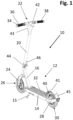
- Fig. 1 shows an electric scooter 10 according to the present invention having a scoter body 12 with a horizontal main body 14 carrying at its front a support 16 tilted upwards and carrying a sleeve 18 for a stem 20 carrying at its upper end a handlebar 22 and at its lower end a front fork 24 for a front wheel 26 of the scooter 10.
- the main body 14 carries a rear fork 28 holding a rear wheel 30.
- a deck 32 is provided for a person to stand on and to operate the scooter.
- a kickstand 15 is provided for parking the scooter 10.
- the front wheel 26 comprises a disc brake (not shown) which is connected to a brake lever 34.
- the handlebar 22 comprises two grips 36, 38, from which the right one 38 is a turnable accelerator grip for operating an elevator motor 40 located in the rear wheel 30, which is protected by a mudguard 41, carrying at its rear a rear light 45 and eventually a stop light.
- a display 42 is provided to indicate the speed and eventually some other status information of the scooter, as e.g. battery charge level.
- a head light 43 is located at the upper end of the stem .
- the main body 14 carries a releasably mounted battery (not shown) as well as a scooter controller (not shown) for all scooter functions, the uppermost part of it being a motor controller.
- the scooter comprises a folding mechanism 44 with a quick release lever 46 via which the stem 20 above the support 16 can be folded backwards to the main body 14.
- the rear wheel 28 is mounted on an axle 48 ( Fig. 3 ) which is - fixed against rotation - mounted to the rear fork 28.
- the motor axle 48 carries a stator 50 with a stator iron core 52 carrying a stator winding 54.
- the outermost iron sheet 56 of the stator iron core 52 (see particularly Fig. 4 ) carries a printed circuit board 58 (PCBA) of the motor controller which is electrically connected a temperature sensor 60 ( Fig. 5 ), which is preferably a mechanical temperature sensor, e.g. a bimetallic type temperature switch.
- the temperature sensor 60 is clamped via the PCBA 58 in contact with the stator winding 54.
- a thermal conductive material e.g. a thermal adhesive, might be used, which improves the transmission the heat generated by the stator iron core winding coil better and faster to the temperature sensor.
- a rotor 62 comprising permanent magnets is rotatably fixed to a planetary gear 64 which again is connected to a rim 66 carrying the tire 68 of the rear wheel.
- the used temperature sensor 60 shown in Fig. 5 is a simple mechanical temperature switch of the bimetallic type.
- the bimetallic switch temperature sensor 60 comprises a second switch contact 78, which is contacted by the movable contact element below a limit temperature. Above that limit temperature the bimetallic strip bends upwards as to release the movable contact element 72 from the second switch contact 78.
- the bimetallic strip 74 is connected to the heat contact area 75 of the sensor 60 so that the temperature of the bimetallic strip reflects quite well the temperature of the heat contact area 75 which is in contact with the motor winding 54 by the pressure of the PCBA 58 and imprived by a heat conductive material (not shown).
- this temperature sensor is directly in contact with the stator winding 54 it is able to immediately and in real time sense the winding temperature and if the winding becomes too hot, i.e. reaches the limit temperature and the temperature sensor 60 opens. This overheating may happen when the motor is overloaded, e.g. when driving a slope upwards over a longer time.
- the temperature sensor 60 is for example via the PCBA 58 connected to the motor controller of the scooter.
- the temperature sensor 60 monitors the temperature generated by the stator core winding 54 in real-time. When the temperature reaches the predetermined limit, the temperature sensor 60 opens and transmits an over temperature control signal to the motor controller through the PCBA circuit board 58, causing the motor 40 to stop running or reduce power operation, so that the motor is able to cool down without being damaged.
- the bimetallic type switch temperature sensor 60 closes and the motor 40 is able to start again. Accordingly, the temperature protection of the present invention for the scooter motor 40 is easy to operate and use.
Landscapes
- Engineering & Computer Science (AREA)
- Power Engineering (AREA)
- Life Sciences & Earth Sciences (AREA)
- Sustainable Development (AREA)
- Sustainable Energy (AREA)
- Transportation (AREA)
- Mechanical Engineering (AREA)
- Microelectronics & Electronic Packaging (AREA)
- Electric Propulsion And Braking For Vehicles (AREA)
Abstract
The present invention relates to an electric scooter motor (40) comprising a stator (50) and a rotor (62), the stator (50) of the scooter motor comprising a stator winding (54). The scooter motor (40) comprises at least one temperature sensor (60) configured to output a temperature signal to a motor controller of an electric scooter (10). According to the invention the at least one temperature sensor (60) is located in connection with the stator winding (54) which allows an effective protection of the scooter motor (40).
Description
- The present invention relates to an electric scooter motor. With the development of modern society and the acceleration of people's pace of life, electric scooters are becoming increasingly popular as a solution for people's last mile of travel. The electric motor used in electric scooters requires small size, light weight, and high torque, so it is easy to accumulate temperature and cause damage to the motor under the working conditions of long-distance climbing with large loads, posing a safety hazard during travel.
- The existing electric scooter motors according to the present invention comprise a stator and a rotor, whereby the stator of the scooter motor comprises stator winding, and the scooter motor comprises at least one temperature sensor configured to output a temperature signal to a motor controller of an electric scooter.
- In prior art this temperature sensor is usually an NTC thermistor located at the motor body and any motor overheat protection function of an electric scooter is generally achieved by sampling and calculating the motor controller ADC circuit. Anyway, this well-known temperature protection is troublesome as the temperature drift is large, and the consistency of mass production is difficult to control, resulting in high control costs. At the same time, the protection function is prone to failure, causing a large number of after-sales complaints and costs.
- It is object of the present invention to overcome the above mentioned drawbacks of the prior art, and to provide an electric scooter motor with a reliable and fast-reacting temperature protection.
- The object is solved with an electric scooter motor according to claim 1 and with an electric scooter according to
claim 10. Advantageous embodiments of the invention are subject matter of the corresponding dependent claims. Preferred embodiments of the invention are described in the specification and in the drawings, too. - To address the shortcomings of existing technology the present invention provides at least one temperature sensor being located in connection with the stator winding, e.g. in contact with their surface and/or in a gap between the stator winding, in any case in close vicinity to the stator winding, so that the winding temperature or its changes can be reliably and quickly be sensed by the temperature sensor.
- This temperature sensor can be used solely or additionally to the above mentioned NTC temperature sensor. When the temperature sensor indicated a pre-selected temperature value, the temperature sensor or a protection circuit of an overheating device acts, and an over-temperature control signal is transmitted to the motor controller to indicate an over-temperature condition or limit the output power of the scooter motor to a limit value or finally to stop the motor from working or, so that the scooter motor is able to cool down without being damaged.
- The term "in connection with" of claim 1 specifies either a direct physical contact or a contact via a heat-conducting element or material, e.g. a heat-conducting paste, or its location in immediate vicinity of the motor winding, so that the heat of the motor winding can immediately affect the temperature sensor, as to enable it to sense the temperature in real-time. Such an immediate vicinity would probably extend within the range of few millimetres.
- According to a preferred embodiment of the invention the scooter motor is a brushless DC motor, which proved very reliable as drive motor of an electric scooter.
- Preferably, the at least one temperature sensor is bonded to the stator winding via a thermal conductive material, particularly silicone grease. This conductive material has a thermal conductivity coefficient ≥ 3 and is thus adapted to provide a very good temperature conduction between the stator winding and the temperature sensor.
- According to a preferred embodiment of the invention the at least one temperature sensor is a mechanical temperature sensor. A mechanical temperature sensor has the advantage, that it is not affected by software/hardware circuits, thus making temperature detection more stable and reliable. Particularly, mechanical temperature sensors do not have any temperature drift characteristics, which is obligatory for semiconductors so that long-term use of the mechanical temperature sensor will not cause any drift in the temperature detection and thus possibly also in the setting of a temperature limit. Further, mechanical temperature sensors are easy to control for consistency during mass production and resulting in significant temperature fluctuations during mass production and finally mechanical temperature sensor signals are not as susceptible to interference as ADC circuits prompt to temperature limiting failures.
- Preferably, the mechanical temperature sensor is a bimetallic contact type mechanical switch. This kind of mechanical temperature sensor is well adapted for the temperature conditions of an electric scooter motor. It is very reliable and has a long life-time without showing any temperature drift. When the bimetallic temperature sensor detects overheating of the stator winding, it sends an open circuit signal (normally closed) or a short circuit signal (normally open) to the motor controller.
- In an advantageous embodiment of the invention the mechanical temperature sensor is configured to open at an upper limit temperature and close again after a lower limit temperature.
- The preferred upper limit temperature for the temperature sensor may e.g. be 140 °C, and the lower limit temperature which is an over-temperature relief value, at which the bimetallic sensor switch closes again, might be 100 °C. Thus, the temperature sensor enables operation of the motor after the scooter motor has cooled down to a normal operation temperature.
- In a preferred embodiment of the invention the at least one temperature sensor is installed in a gap between the stator winding, in which location the temperature conditions quite exactly mirror the temperature of the stator winding. This arrangement of the temperature sensor does not necessarily requires a direct physical contact with the winding.
- Additionally and/or alternatively the temperature sensor may be located in contact with the surface of the stator winding which ensures excellent thermal transition between the winding and the temperature sensor. This contact can either be a direct physical contact with the winding surface or a contact via a thermal conductor, e.g. a thermal conductivity paste etc..
- Advantageously, the scooter motor has a temperature protection circuit provided on a printed circuit board (PCBA) located in connection with the scooter motor. Via this measure, the temperature protection circuit is separated from other electronics and circuits of an electric scooter, so that the reliability of a temperature protection, based on this arrangement is very reliable. This, integration of the temperature protection circuit with the motor also has the advantage that the circuit is optimally configured for the motor. Thus, no erroneous link of a protection circuit and a scooter motor may happen, which may happen, if such an integration is not present, as it happens with external components. The output signal of the temperature protection circuit may further directly be used, e.g. to switch off the scooter motor, aside of any other scooter electronics. Accordingly, this is a very reliable and failure-free and interference-free protection of the scooter motor.
- Preferably, the at least one temperature sensor is installed via said printed circuit board to the stator winding to keep it from losing contact with the surface of the stator winding. Thus, this PCBA has the double function of integrating the temperature protection circuit with the motor and for keeping the temperature sensor in place.
- According to a preferred embodiment of the invention the at least one temperature sensor is configured to output a temperature signal indicating at least two different temperatures of the stator winding. This detection of two different limit temperatures can be realised with one or two mechanical sensors. The provision of two different limit temperatures allows a stepwise reduction of the motor load. For example can a first limit temperature be used to indicate an overheat-situation or to limit the motor power and a second higher temperature may than be used to limit the motor power or to switch the motor off. This stepwise temperature supervision has the advantage that the scooter used is informed about the overheat-situation before the motor power is reduced or the motor is even switched off. The output power of the motor can e.g. be limited by limiting the feed current to the motor to ≤ 8A.
- The invention also relates to an electric scooter comprising a scooter motor according to the above described embodiments and a motor controller for the scooter motor and wherein the rotor of the scooter motor being connected to a gear connected to a drive axis of a scooter wheel, wherein the motor controller is connected to the at least one temperature sensor of the scooter motor, which motor controller is configured to issue at least one safety action for the electric scooter in case of over-temperature of the scooter motor.
- Advantageously, the safety action comprises at least one of the following actions:
- indicating an over-temperature situation of the scooter motor on a display of the scooter,
- indicating acoustically an over-temperature situation of the scooter motor,
- limiting the power of the scooter motor, and
- switching off the scooter motor.
- The safety actions might thus be in a range from simple warnings to cutting of the electric motor, e.g. by cutting the power supply thereto.
- In a preferred embodiment of the invention the at least one temperature sensor is configured to output a signal indicating at least two different temperatures to the motor controller, whereby at a first temperature the motor controller is configured to indicate an over-temperature situation of the scooter motor on a display of the scooter and/or acoustically and whereby at a second temperature the motor controller is configured to limit the motor power of the scooter motor and/or to switch off the scooter motor.
- Correspondingly, the at least one temperature sensor is in this case configured to output a temperature signal comprising at least three different sensed temperatures to the temperature monitoring device, and in that at a third temperature the motor controller is configured to switch off the scooter motor.
- This could be e.g. a bimetallic sensor with several contacts at different positions of the bimetal or several mechanical sensors, e.g. bimetallic sensors. Alternatively, an electric or electronic sensor might be used which is able to output several temperatures, e.g. an analogue or digital temperature sensor.
- In its most simple embodiment the motor controller may be a switch to cut off the motor from its power supply.
- Following terms are used as synonyms: scooter - electric scooter; motor - scooter motor;
- The invention is now described by aid of the enclosed schematic drawing, in which
- Fig. 1
- shows a perspective view of an electric scooter,
- Fig. 2
- shows a view according to
Fig. 1 with an explosion view of the the rear wheel with the scooter motor, - Fig. 3
- shows an enlargement of the explosion view of the rear wheel of
Fig. 2 , - Fig. 4
- shows a further enlargement of
Fig. 3 only showing the iron stator core of the motor with the stator winding and a uppermost iron sheet of the iron stator core carrying a temperature sensor an a PCBA of the motor controller, and - Fig. 5
- shows a sectional view through a bimetallic temperature sensor for the use in the electric scooter of
Fig. 1 . -
Fig. 1 shows anelectric scooter 10 according to the present invention having ascoter body 12 with a horizontalmain body 14 carrying at its front asupport 16 tilted upwards and carrying a sleeve 18 for astem 20 carrying at its upper end ahandlebar 22 and at its lower end afront fork 24 for afront wheel 26 of thescooter 10. At its rear themain body 14 carries arear fork 28 holding arear wheel 30. On the top of the main body 14 adeck 32 is provided for a person to stand on and to operate the scooter. On the side of the main body 14 akickstand 15 is provided for parking thescooter 10. - The
front wheel 26 comprises a disc brake (not shown) which is connected to abrake lever 34. Thehandlebar 22 comprises twogrips right one 38 is a turnable accelerator grip for operating anelevator motor 40 located in therear wheel 30, which is protected by amudguard 41, carrying at its rear arear light 45 and eventually a stop light. In the middle of the handlebar 22 adisplay 42 is provided to indicate the speed and eventually some other status information of the scooter, as e.g. battery charge level. At the upper end of the stem ahead light 43 is located. Below thedeck 32 themain body 14 carries a releasably mounted battery (not shown) as well as a scooter controller (not shown) for all scooter functions, the uppermost part of it being a motor controller. - For a better transportability the scooter comprises a
folding mechanism 44 with aquick release lever 46 via which thestem 20 above thesupport 16 can be folded backwards to themain body 14. - Essential components of the
motor 40 are visible from the explosion view ofFigs. 2 to 4 . - The
rear wheel 28 is mounted on an axle 48 (Fig. 3 ) which is - fixed against rotation - mounted to therear fork 28. Themotor axle 48 carries astator 50 with astator iron core 52 carrying a stator winding 54. - The
outermost iron sheet 56 of the stator iron core 52 (see particularlyFig. 4 ) carries a printed circuit board 58 (PCBA) of the motor controller which is electrically connected a temperature sensor 60 (Fig. 5 ), which is preferably a mechanical temperature sensor, e.g. a bimetallic type temperature switch. Thetemperature sensor 60 is clamped via thePCBA 58 in contact with the stator winding 54. For the contact of the temperature sensor to the stator winding additionally a thermal conductive material, e.g. a thermal adhesive, might be used, which improves the transmission the heat generated by the stator iron core winding coil better and faster to the temperature sensor. - Around the stator winding a
rotor 62 comprising permanent magnets is rotatably fixed to aplanetary gear 64 which again is connected to arim 66 carrying thetire 68 of the rear wheel. - On the left side the
motor 40 is protected by acover 70. - The used
temperature sensor 60 shown inFig. 5 is a simple mechanical temperature switch of the bimetallic type. - It comprises a
movable contact element 72 which is carried by a temperature sensitivebimetallic strip 74. Themovable contact element 72 is connected via thebimetallic strip 74 to afirst switch contact 76. The bimetallicswitch temperature sensor 60 comprises asecond switch contact 78, which is contacted by the movable contact element below a limit temperature. Above that limit temperature the bimetallic strip bends upwards as to release themovable contact element 72 from thesecond switch contact 78. Thebimetallic strip 74 is connected to theheat contact area 75 of thesensor 60 so that the temperature of the bimetallic strip reflects quite well the temperature of theheat contact area 75 which is in contact with the motor winding 54 by the pressure of thePCBA 58 and imprived by a heat conductive material (not shown). - As this temperature sensor is directly in contact with the stator winding 54 it is able to immediately and in real time sense the winding temperature and if the winding becomes too hot, i.e. reaches the limit temperature and the
temperature sensor 60 opens. This overheating may happen when the motor is overloaded, e.g. when driving a slope upwards over a longer time. - The
temperature sensor 60 is for example via thePCBA 58 connected to the motor controller of the scooter. - Thus, the
temperature sensor 60 monitors the temperature generated by the stator core winding 54 in real-time. When the temperature reaches the predetermined limit, thetemperature sensor 60 opens and transmits an over temperature control signal to the motor controller through thePCBA circuit board 58, causing themotor 40 to stop running or reduce power operation, so that the motor is able to cool down without being damaged. - After the motor has cooled down to a certain value the bimetallic type
switch temperature sensor 60 closes and themotor 40 is able to start again. Accordingly, the temperature protection of the present invention for thescooter motor 40 is easy to operate and use. - The invention is not limited by the above description of a preferred embodiment but may be varied within the scope of the appended patent claims.
-
- 10
- Electric scooter
- 12
- scooter body
- 14
- main body
- 15
- kickstand
- 16
- support
- 18
- sleeve
- 20
- stem
- 22
- handlebar
- 24
- front fork
- 26
- front wheel
- 28
- rear fork
- 30
- rear wheel
- 32
- deck
- 34
- brake lever
- 36
- left grip
- 38
- right turnable accelerator grip
- 40
- scooter motor (brushless DC motor)
- 41
- mudguard
- 42
- display
- 43
- head light - front light
- 44
- folding mechanism
- 45
- rear light
- 46
- quick release lever of the folding mechanism
- 48
- rotationally fixed rear axle of rear wheel
- 50
- stator of the motor (stator iron core with winding)
- 52
- stator iron core
- 54
- stator winding
- 56
- outermost iron sheet of the stator iron core
- 58
- printed circuit board
- 60
- temperature sensor - bimetallic type temperature switch
- 62
- rotor with permanent magnets
- 64
- planetary gear between rotor and wheel rim
- 66
- wheel rim
- 68
- wheel tire
- 70
- cover
- 72
- movable contact element
- 74
- bimetallic strip carrying and contacting the movable contact element
- 75
- heat contact area of the temperature sensor
- 76
- first switch contact
- 78
- second switch contact
Claims (15)
- Electric scooter motor (40) comprising a stator (50) and a rotor (62), the stator (50) of the scooter motor comprising a stator winding (54), the scooter motor (40) comprising at least one temperature sensor (60) configured to output a temperature signal to a motor controller of an electric scooter (10), characterized in that the at least one temperature sensor (60) is located in connection with the stator winding (54).
- Scooter motor (40) according to claim 1, the scooter motor (40) being a brushless DC motor.
- Scooter motor (40) according to claim 1 or 2, characterized in that the at least one temperature sensor (60) is bonded to the stator winding via a thermal conductive material, particularly silicone grease.
- Scooter motor (40) according to one of the preceding claims, characterized in that the at least one temperature sensor (60) is a mechanical temperature sensor.
- Scooter motor (40) according to claim 4, characterized in in that the mechanical temperature sensor (60) is a bimetallic contact type mechanical switch.
- Scooter motor (40) according to claim 4 or 5, characterized in in that the mechanical temperature sensor (60) is configured to open at an upper limit temperature and close again after a lower limit temperature.
- Scooter motor (40) according to one of the preceding claims, characterized in that the at least one temperature sensor (60) is installed in a gap between the stator winding.
- Scooter motor (40) according to one of the preceding claims, characterized in that the at least one temperature sensor (60) is installed in contact with the surface of the stator winding (54).
- Scooter motor (40) according to one of the preceding claims, characterized in that it has a temperature protection circuit provided on a printed circuit board (PCBA) (58) located in connection with the scooter stator (50).
- Scooter motor (40) according to claim 9, characterized in that the at least one temperature sensor (60) is installed via said printed circuit board (58) to the stator winding (54) to keep it from losing contact with the surface of the stator winding (54).
- Scooter motor (40) according to one of the preceding claims, characterized in that the at least one temperature sensor (60) is configured to output a temperature signal indicating at least two different temperatures of the stator winding (54).
- Electric scooter comprising a scooter motor (40) according to one of the preceding claims and a motor controller for the scooter motor (40) and wherein the rotor of the scooter motor (40) being connected to a gear (64) connected to a scooter wheel (30), wherein the motor controller is connected to the at least one temperature sensor (60) of the scooter motor (40), which motor controller is configured to issue at least one safety action for the electric scooter (10) in case of over-temperature of the scooter motor (40) as indicated by the temperature sensor (60).
- Electric scooter according to claim 12, characterized in that the safety action comprises at least one of the following actions:- indicating an over-temperature situation of the scooter motor (40) on a display (42) of the scooter (10),- indicating acoustically an over-temperature situation of the scooter motor (40),- limiting the power of the scooter motor (40), and- switching off the scooter motor (40).
- Electric scooter (10) according to claim 12 or 13, wherein the at least one temperature sensor (60) is configured to output a signal indicating at least two different temperatures to the motor controller, whereby at a first temperature the motor controller is configured to indicate an over-temperature situation of the scooter motor (40) on a display of the scooter and/or acoustically and whereby at a second temperature the motor controller is configured to limit the motor power of the scooter motor (40) and/or to switch off the scooter motor (40).
- Electric scooter according to claim 14, characterized in that the at least one temperature sensor (60) is configured to output a temperature signal comprising at least three different sensed temperatures to the temperature monitoring device, and in that at a third temperature the motor controller is configured to switch off the scooter motor (40).
Priority Applications (1)
| Application Number | Priority Date | Filing Date | Title |
|---|---|---|---|
| EP23175977.0A EP4472040A1 (en) | 2023-05-30 | 2023-05-30 | Electric scooter motor |
Applications Claiming Priority (1)
| Application Number | Priority Date | Filing Date | Title |
|---|---|---|---|
| EP23175977.0A EP4472040A1 (en) | 2023-05-30 | 2023-05-30 | Electric scooter motor |
Publications (1)
| Publication Number | Publication Date |
|---|---|
| EP4472040A1 true EP4472040A1 (en) | 2024-12-04 |
Family
ID=86609453
Family Applications (1)
| Application Number | Title | Priority Date | Filing Date |
|---|---|---|---|
| EP23175977.0A Pending EP4472040A1 (en) | 2023-05-30 | 2023-05-30 | Electric scooter motor |
Country Status (1)
| Country | Link |
|---|---|
| EP (1) | EP4472040A1 (en) |
Citations (4)
| Publication number | Priority date | Publication date | Assignee | Title |
|---|---|---|---|---|
| US5343613A (en) * | 1993-01-27 | 1994-09-06 | Sundstrand Corporation | Method of installing thermal protection for an electric motor stator |
| JPH1042520A (en) * | 1996-05-24 | 1998-02-13 | Sony Corp | Motors for mobile devices |
| CN106672140A (en) * | 2015-01-06 | 2017-05-17 | 刘岗 | Scooter and driving control system |
| US20210297033A1 (en) * | 2018-07-19 | 2021-09-23 | Afang SUN | Motor and Control Method Therefor |
-
2023
- 2023-05-30 EP EP23175977.0A patent/EP4472040A1/en active Pending
Patent Citations (4)
| Publication number | Priority date | Publication date | Assignee | Title |
|---|---|---|---|---|
| US5343613A (en) * | 1993-01-27 | 1994-09-06 | Sundstrand Corporation | Method of installing thermal protection for an electric motor stator |
| JPH1042520A (en) * | 1996-05-24 | 1998-02-13 | Sony Corp | Motors for mobile devices |
| CN106672140A (en) * | 2015-01-06 | 2017-05-17 | 刘岗 | Scooter and driving control system |
| US20210297033A1 (en) * | 2018-07-19 | 2021-09-23 | Afang SUN | Motor and Control Method Therefor |
Similar Documents
| Publication | Publication Date | Title |
|---|---|---|
| KR102808477B1 (en) | Connector with integrated thermal shield for battery pack | |
| TW300207B (en) | ||
| EP3372439A1 (en) | Mobile body using removable battery | |
| JP6072429B2 (en) | Transmission device and transmission method for transmitting current to components of a steering wheel of an automobile | |
| JP2012236590A5 (en) | ||
| MXPA02011778A (en) | BATTERY FOR A VEHICLE ASSEMBLED BY CHILDREN. | |
| JPS628419A (en) | Circuit breaker with overheating preventor | |
| CN210953143U (en) | Busbar temperature-taking device for frame circuit breaker | |
| WO2025161678A1 (en) | Vehicle control method and vehicle | |
| CN215118764U (en) | An over-temperature sensing switch device for a distribution box | |
| CN102931636B (en) | Overload overtemperature early warning protection device with manual reset | |
| JP3960135B2 (en) | Brush motor for vehicle drive device and control method thereof | |
| CN107719564A (en) | One kind brake power-off inductive switch | |
| CN223208271U (en) | Food processor cup and food processor | |
| JP2005050744A (en) | Cylindrical alkaline storage battery and charger | |
| CN2620450Y (en) | Temp detection type pass load-speaker protector | |
| CN214848421U (en) | Overcurrent protector with indicating lamp | |
| CN202230952U (en) | Heat protector for inverter air condition compressor | |
| CN209462005U (en) | Current interruption device and electric motor with current inlet | |
| CN213026007U (en) | A temperature detection system and its circuit breaker | |
| CN201222645Y (en) | Automatic protection construction device for preventing three-phase AC electric motor from burning | |
| CN214848449U (en) | Anti-press-error overcurrent protector | |
| CN210378921U (en) | Low-voltage distribution protection device | |
| CN211765827U (en) | Steering wheel assembly with heating function | |
| CN113270299B (en) | Overcurrent protector with indicating lamp |
Legal Events
| Date | Code | Title | Description |
|---|---|---|---|
| PUAI | Public reference made under article 153(3) epc to a published international application that has entered the european phase |
Free format text: ORIGINAL CODE: 0009012 |
|
| STAA | Information on the status of an ep patent application or granted ep patent |
Free format text: STATUS: THE APPLICATION HAS BEEN PUBLISHED |
|
| AK | Designated contracting states |
Kind code of ref document: A1 Designated state(s): AL AT BE BG CH CY CZ DE DK EE ES FI FR GB GR HR HU IE IS IT LI LT LU LV MC ME MK MT NL NO PL PT RO RS SE SI SK SM TR |
|
| STAA | Information on the status of an ep patent application or granted ep patent |
Free format text: STATUS: REQUEST FOR EXAMINATION WAS MADE |
|
| 17P | Request for examination filed |
Effective date: 20250528 |
|
| RAP1 | Party data changed (applicant data changed or rights of an application transferred) |
Owner name: SOFLOW MOBILITY GMBH |