EP4472037A1 - Rotating electric machine - Google Patents
Rotating electric machine Download PDFInfo
- Publication number
- EP4472037A1 EP4472037A1 EP22923762.3A EP22923762A EP4472037A1 EP 4472037 A1 EP4472037 A1 EP 4472037A1 EP 22923762 A EP22923762 A EP 22923762A EP 4472037 A1 EP4472037 A1 EP 4472037A1
- Authority
- EP
- European Patent Office
- Prior art keywords
- brush holder
- accommodating portion
- cover
- electric machine
- rotating electric
- Prior art date
- Legal status (The legal status is an assumption and is not a legal conclusion. Google has not performed a legal analysis and makes no representation as to the accuracy of the status listed.)
- Granted
Links
Images


Classifications
-
- H—ELECTRICITY
- H02—GENERATION; CONVERSION OR DISTRIBUTION OF ELECTRIC POWER
- H02K—DYNAMO-ELECTRIC MACHINES
- H02K5/00—Casings; Enclosures; Supports
- H02K5/04—Casings or enclosures characterised by the shape, form or construction thereof
- H02K5/14—Means for supporting or protecting brushes or brush holders
- H02K5/141—Means for supporting or protecting brushes or brush holders for cooperation with slip-rings
-
- B—PERFORMING OPERATIONS; TRANSPORTING
- B60—VEHICLES IN GENERAL
- B60K—ARRANGEMENT OR MOUNTING OF PROPULSION UNITS OR OF TRANSMISSIONS IN VEHICLES; ARRANGEMENT OR MOUNTING OF PLURAL DIVERSE PRIME-MOVERS IN VEHICLES; AUXILIARY DRIVES FOR VEHICLES; INSTRUMENTATION OR DASHBOARDS FOR VEHICLES; ARRANGEMENTS IN CONNECTION WITH COOLING, AIR INTAKE, GAS EXHAUST OR FUEL SUPPLY OF PROPULSION UNITS IN VEHICLES
- B60K1/00—Arrangement or mounting of electrical propulsion units
-
- H—ELECTRICITY
- H01—ELECTRIC ELEMENTS
- H01R—ELECTRICALLY-CONDUCTIVE CONNECTIONS; STRUCTURAL ASSOCIATIONS OF A PLURALITY OF MUTUALLY-INSULATED ELECTRICAL CONNECTING ELEMENTS; COUPLING DEVICES; CURRENT COLLECTORS
- H01R39/00—Rotary current collectors, distributors or interrupters
- H01R39/02—Details for dynamo electric machines
- H01R39/38—Brush holders
- H01R39/385—Means for mechanical fixation of the brush holder
Definitions
- the present invention relates to a rotating electric machine.
- abrasion powder of the brush or the like is generated due to friction between the brush and a rotor shaft.
- abrasion powder is accumulated, an insulation property of the rotating electric machine is deteriorated.
- JP 2871003 B discloses a rotating electric machine in which a concave portion is provided on a side surface of a brush, and the brush is abraded to the concave portion by a commutator, thereby abrading a fixed matter of the abrasion powder during rotation. Accordingly, it is possible to prevent a short circuit between commutators.
- an object of the present invention is to provide a rotating electric machine capable of preventing deterioration in an insulation property between a brush and a housing due to abrasion powder.
- the present invention is applied to a rotating electric machine including a brush holder that holds brushes.
- a first cover through which a rotor shaft passes is provided on one end side in an axial direction.
- a brush holder accommodating portion that accommodates the brush holder is recessed in the first cover in the axial direction from an outer side of the first cover.
- the brush holder is disposed in the brush holder accommodating portion such that a distance between a lower surface of the brush holder and an inner peripheral wall of the brush holder accommodating portion is larger than a distance between another portion of the brush holder and another inner peripheral wall of the brush holder accommodating portion.
- the brush holder is disposed such that the distance between the lower surface of the brush holder and the inner peripheral wall of the brush holder accommodating portion is larger than the distance between the another portion of the brush holder and the another inner peripheral wall of the brush holder accommodating portion, so that a space on a lower surface side of the brush holder can be increased. Accordingly, even if abrasion powder of the brush is accumulated in this space, an insulation distance between the brush and a housing can be maintained. In this way, it is possible to prevent deterioration in an insulation property between the brush and the housing.
- FIG. 1 is an explanatory diagram when a drive unit 100 including a rotating electric machine 1 of the present embodiment is observed from a side in an axial direction.
- FIG. 2 is an explanatory diagram of the drive unit 100 and shows a state where a second cover 22 and a bus bar cover 26 are mounted.
- the drive unit 100 includes the rotating electric machine 1 and an inverter unit 3 that supplies electric power to the rotating electric machine 1.
- the inverter unit 3 is mounted on an upper portion of the rotating electric machine 1.
- the rotating electric machine 1 includes a housing 2 that accommodates a rotor and a stator (not shown).
- the rotor includes a rotor shaft 11.
- the housing 2 includes a refrigerant flow path through which a refrigerant (cooling oil) for cooling circulates, and a refrigerant inlet 2a and a refrigerant outlet 2b through which the refrigerant flows into and out of the housing 2.
- the rotating electric machine 1 is mounted on a vehicle and functions as an electric motor that drives wheels.
- the rotating electric machine 1 also functions as an electric power generator that generates (regenerates) electric power by receiving a driving force generated by rotation of the wheels.
- the rotating electric machine 1 is implemented by a winding field type electric motor.
- the housing 2 has an internal cavity shape having an opening, and the stator and the rotor are accommodated in the internal cavity.
- the opening that is open on the side of the axial direction (front side in FIG. 1 ) of the housing 2 is covered with a first cover 21.
- the second cover 22 and the bus bar cover 26 are attached to an outer side of the first cover 21.
- the rotor shaft 11 protrudes outward from the first cover 21 and rotatably supports the rotor shaft 11.
- the housing 2, the first cover 21, the second cover 22, and the bus bar cover 26 are formed by casting using a metal such as an aluminum alloy.
- Slip rings 12 are provided on an outer periphery of the rotor shaft 11. Brushes 5 come into contact with the slip rings 12, and the inverter unit 3 and field winding provided on the rotor are electrically connected via the brushes 5, so that direct current electric power from the inverter unit 3 is supplied to the field winding.
- the brushes 5 are held by a brush holder 15 in a state of being accommodated in the brush holder 15, and are fixed with respect to the rotor shaft 11.
- the brush holder accommodating portion 20 communicates with a communication portion 23 that is formed shallowly in the axial direction at an upper portion thereof.
- the communication portion 23 further communicates with a connection portion 24 that is recessed in the axial direction at an upper portion thereof.
- Tip ends of field bus bars 241 to which the direct current electric power of the inverter unit 3 is supplied are accommodated in the connection portion 24.
- Wiring 19 is connected between the field bus bars 241 and the brush holder 15.
- the wiring 19 is routed in an up-down direction from the connection portion 24 to the brush holder accommodating portion 20 via the communication portion 23. Each end of the wiring 19 is connected to the brush 5.
- FIG. 4 is an explanatory diagram showing a case where the drive unit 100 of the present embodiment is mounted on the vehicle.
- three mount brackets 101 are fixed to the drive unit 100, and the drive unit 100 is supported by a suspension member 110 via the mount brackets 101.
- the mount brackets 101 are provided at two locations on a front side in a vehicle front-rear direction of the drive unit 100 and at both ends in a vehicle width direction, and at one location on a rear side in the vehicle front-rear direction of the drive unit 100 and at a center in the vehicle width direction.
- the drive unit 100 is disposed such that the center of gravity thereof is located approximately at a center of a triangle connecting the positions of the three mount brackets 101.
- the suspension member 110 supporting the drive unit 100 is fixed to a vehicle body.
- the brushes 5 are arranged in a V-shape on one side (left side in the drawing, vehicle rear side) of the rotor shaft 11 in the brush holder 15. Therefore, the brush holder accommodating portion 20 is disposed at a position biased to the vehicle rear side (one side) with respect to the rotor shaft 11.
- the inverter unit 3 can be disposed above the rotating electric machine 1 and integrally with the rotating electric machine 1. Since the rotating electric machine 1 includes the stator and the rotor in the housing 2 having high rigidity, the inverter unit 3 is protected by the rotating electric machine 1 having high rigidity and a case is prevented from being broken even at the time of a collision, for example.
- the rotating electric machine 1 includes the housing 2 including the first cover 21 through which the rotor shaft 11 passes.
- the brush holder accommodating portion 20 that accommodates the brush holder 15 is recessed in the first cover 21 in the axial direction from the outer side of the first cover 21.
- the brush holder 15 is disposed in the brush holder accommodating portion 20 such that the distance (A) between the lower surface 15a of the brush holder 15 and the inner peripheral wall 20a of the brush holder accommodating portion 20 facing the lower surface 15a is larger than the distance between the another peripheral surface 15b of the brush holder 15 and the another inner peripheral wall 20b of the brush holder accommodating portion 20 facing the another peripheral surface 15b.
- the abrasion powder accumulation portion 29 having a sufficient capacity to accumulate the abrasion powder can be provided below the brush holder 15.
- the abrasion powder of the brush 5 is accumulated in the abrasion powder accumulation portion 29. Accordingly, even when the abrasion powder of the brush is accumulated in the abrasion powder accumulation portion 29, the insulation distance between the brush 5 and the housing 2 (and the first cover 21) can be maintained. In this way, it is possible to prevent the deterioration in the insulation property between the brush 5 and the housing 2.
- the space surrounded by the lower surface 15a of the brush holder 15, the inner peripheral wall 20a of the brush holder accommodating portion 20, the first cover 21, and the second cover 22 is configured as the abrasion powder accumulation portion 29 in which the abrasion powder of the brushes 5 is accumulated.
- the rotor shaft 11 is provided with a plurality of electrodes (slip rings 12) at positions separated from each other in the axial direction, and the brush holder 15 holds the brushes 5 such that one pair of brushes 5 comes into contact with one electrode (positive electrode) and another pair of brushes 5 comes into contact with another one electrode (negative electrode).
- the brush holder 15 can be disposed at the position biased to the vehicle rear side with respect to the rotor shaft 11 by bringing the pair of brushes 5 into contact with the each of the slip rings 12 from the vehicle rear side (one side) in a V-shape.
- the rotating electric machine 1 is supported by the vehicle body via the suspension member 110, the mount bracket 101 configured to connect the rotating electric machine 1 and the suspension member 110 is provided on the outer side of the first cover 21, and the mount bracket 101 is disposed at a position biased to the vehicle front side with respect to the rotor shaft 11 and the brush holder accommodating portion 20.
- the mount bracket 101 fixed to the side surface of the drive unit 100 can be disposed at the vehicle front side with respect to the rotor shaft 11, which is an optimum position with respect to the drive unit 100. Accordingly, the mount bracket 101 supporting the rotating electric machine 1 can be disposed at an appropriate position while not interfering with opening and closing of the second cover 22 covering the brush holder accommodating portion 20.
- the distance between the lower surface 15a of the brush holder 15 and the inner peripheral wall 20a of the brush holder accommodating portion 20 can be increased.
Landscapes
- Engineering & Computer Science (AREA)
- Power Engineering (AREA)
- Chemical & Material Sciences (AREA)
- Combustion & Propulsion (AREA)
- Transportation (AREA)
- Mechanical Engineering (AREA)
- Motor Or Generator Frames (AREA)
Abstract
Description
- The present invention relates to a rotating electric machine.
- In a rotating electric machine including a brush for supplying electric power to a rotor, abrasion powder of the brush or the like is generated due to friction between the brush and a rotor shaft. When such abrasion powder is accumulated, an insulation property of the rotating electric machine is deteriorated.
-
JP 2871003 B - The technique described in the above patent document does not take into account an influence of abrasion powder accumulating in a housing or the like around the brush. Therefore, there is a concern that an insulation property between the brush and the housing is deteriorated.
- In view of such a problem, an object of the present invention is to provide a rotating electric machine capable of preventing deterioration in an insulation property between a brush and a housing due to abrasion powder.
- According to an embodiment of the present invention, the present invention is applied to a rotating electric machine including a brush holder that holds brushes. A first cover through which a rotor shaft passes is provided on one end side in an axial direction. A brush holder accommodating portion that accommodates the brush holder is recessed in the first cover in the axial direction from an outer side of the first cover. The brush holder is disposed in the brush holder accommodating portion such that a distance between a lower surface of the brush holder and an inner peripheral wall of the brush holder accommodating portion is larger than a distance between another portion of the brush holder and another inner peripheral wall of the brush holder accommodating portion.
- According to the present invention, the brush holder is disposed such that the distance between the lower surface of the brush holder and the inner peripheral wall of the brush holder accommodating portion is larger than the distance between the another portion of the brush holder and the another inner peripheral wall of the brush holder accommodating portion, so that a space on a lower surface side of the brush holder can be increased. Accordingly, even if abrasion powder of the brush is accumulated in this space, an insulation distance between the brush and a housing can be maintained. In this way, it is possible to prevent deterioration in an insulation property between the brush and the housing.
-
- [
FIG. 1] FIG. 1 is an explanatory diagram of a rotating electric machine according to an embodiment of the present invention. - [
FIG. 2] FIG. 2 is an explanatory diagram of the rotating electric machine. - [
FIG. 3] FIG. 3 is an explanatory diagram of a brush holder. - [
FIG. 4] FIG. 4 is an explanatory diagram showing a state where the rotating electric machine is mounted on a vehicle. - Hereinafter, an embodiment of the present invention will be described with reference to the drawings or the like.
-
FIG. 1 is an explanatory diagram when adrive unit 100 including a rotatingelectric machine 1 of the present embodiment is observed from a side in an axial direction.FIG. 2 is an explanatory diagram of thedrive unit 100 and shows a state where asecond cover 22 and abus bar cover 26 are mounted. - The
drive unit 100 includes the rotatingelectric machine 1 and aninverter unit 3 that supplies electric power to the rotatingelectric machine 1. Theinverter unit 3 is mounted on an upper portion of the rotatingelectric machine 1. - The rotating
electric machine 1 includes ahousing 2 that accommodates a rotor and a stator (not shown). The rotor includes arotor shaft 11. Thehousing 2 includes a refrigerant flow path through which a refrigerant (cooling oil) for cooling circulates, and arefrigerant inlet 2a and arefrigerant outlet 2b through which the refrigerant flows into and out of thehousing 2. - The rotating
electric machine 1 is mounted on a vehicle and functions as an electric motor that drives wheels. The rotatingelectric machine 1 also functions as an electric power generator that generates (regenerates) electric power by receiving a driving force generated by rotation of the wheels. The rotatingelectric machine 1 is implemented by a winding field type electric motor. - The
housing 2 has an internal cavity shape having an opening, and the stator and the rotor are accommodated in the internal cavity. The opening that is open on the side of the axial direction (front side inFIG. 1 ) of thehousing 2 is covered with afirst cover 21. Thesecond cover 22 and thebus bar cover 26 are attached to an outer side of thefirst cover 21. Therotor shaft 11 protrudes outward from thefirst cover 21 and rotatably supports therotor shaft 11. Thehousing 2, thefirst cover 21, thesecond cover 22, and thebus bar cover 26 are formed by casting using a metal such as an aluminum alloy. -
Slip rings 12 are provided on an outer periphery of therotor shaft 11.Brushes 5 come into contact with theslip rings 12, and theinverter unit 3 and field winding provided on the rotor are electrically connected via thebrushes 5, so that direct current electric power from theinverter unit 3 is supplied to the field winding. - The
brushes 5 are held by abrush holder 15 in a state of being accommodated in thebrush holder 15, and are fixed with respect to therotor shaft 11. -
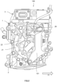
FIG. 3 is an explanatory diagram of thefirst cover 21 centering on a brushholder accommodating portion 20. - The
first cover 21 includes the brushholder accommodating portion 20 in which thebrush holder 15 is accommodated. The brushholder accommodating portion 20 is formed in a concave shape that is recessed from a side surface of the first cover 21 (outermost surface of the first cover 21) toward a back side in the axial direction. The brushholder accommodating portion 20 is formed in a shape that is one size larger than an outer peripheral shape of thebrush holder 15. - The
brush holder 15 is a case made of an insulating resin that accommodates and holds a plurality ofbrushes 5 therein. Thebrush holder 15 includes a throughhole 16 through which therotor shaft 11 passes. - The
rotor shaft 11 is provided with theslip rings 12 as two electrodes, a positive electrode and a negative electrode, in parallel at positions separated from each other in the axial direction. - The
brush holder 15 includes a pair ofbrushes 5 for each of the positive andnegative slip rings 12. Thebrush 5 has a square rod shape, and one end side in a longitudinal direction thereof comes into contact with theslip ring 12 of therotor shaft 11. A biasing member such as a spring is disposed on the other end side of thebrush 5 in the longitudinal direction, and thebrush 5 is pressed toward theslip ring 12. - The pair of
brushes 5 fixed to thebrush holder 15 come into contact with the positive ornegative slip ring 12. An angle between axial center lines in longitudinal directions of the pair ofbrushes 5 is an acute angle. That is, the pair ofbrushes 5 are arranged in a V-shape so as to be separated from each other as being moved away from theslip ring 12. If thebrush holder 15 is disposed biased to one side of therotor shaft 11 as will be described later, thebrushes 5 do not necessarily have to be arranged in a V-shape at an acute angle. - The
brush holder 15 is fixed to a side surface of the brushholder accommodating portion 20 with threebolts 151. - In the
first cover 21, the brushholder accommodating portion 20 communicates with acommunication portion 23 that is formed shallowly in the axial direction at an upper portion thereof. Thecommunication portion 23 further communicates with aconnection portion 24 that is recessed in the axial direction at an upper portion thereof. Tip ends offield bus bars 241 to which the direct current electric power of theinverter unit 3 is supplied are accommodated in theconnection portion 24.Wiring 19 is connected between thefield bus bars 241 and thebrush holder 15. Thewiring 19 is routed in an up-down direction from theconnection portion 24 to the brushholder accommodating portion 20 via thecommunication portion 23. Each end of thewiring 19 is connected to thebrush 5. - As shown in
FIG. 2 , thesecond cover 22 is attached to the brushholder accommodating portion 20 recessed in thefirst cover 21, thecommunication portion 23, and theconnection portion 24 to close these parts from the outside. - A bus
bar accommodating portion 25 is recessed in the axial direction above the brushholder accommodating portion 20 and on a side of theconnection portion 24. Tip ends of three-phase bus bars 41 for supplying three-phase electric power of theinverter unit 3 are accommodated in the busbar accommodating portions 25. As shown inFIG. 2 , thebus bar cover 26 is attached to the busbar accommodating portion 25 to close a concave portion of the busbar accommodating portion 25 from the outside. - In the rotating
electric machine 1 configured as described above, measures against abrasion powder of thebrush 5 will be described. - The
brush 5 is in sliding contact with theslip ring 12, and thebrush 5 and theslip ring 12 are gradually abraded as therotor shaft 11 rotates. The abrasion powder is accumulated inside thebrush holder 15, but the abrasion powder is discharged to the outside of thebrush holder 15 because thebrush holder 15 does not have a sealed structure. The abrasion powder contains a metal component and thus has conductivity, so that when the abrasion powder is accumulated on the outside of thebrush holder 15, an insulation distance between thebrush 5 in thebrush holder 15 and thefirst cover 21 is shortened, which may affect an insulation property. - Further, the rotating
electric machine 1 has a liquid cooling (oil cooling) structure, and thus does not include an air blowing mechanism such as a fan. Therefore, it is not possible to adopt a structure in which a gap is provided in thefirst cover 21 to discharge the abrasion powder to the outside by air blowing and to prevent rainwater from entering from the outside. - Therefore, in the present embodiment, the following configuration is used to prevent an influence on the insulation property due to the accumulated abrasion powder.
- As shown in
FIG. 3 , thebrush holder 15 is disposed in the brushholder accommodating portion 20 such that a distance (indicated by A inFIG. 3 ) between alower surface 15a of thebrush holder 15 and an innerperipheral wall 20a of the brushholder accommodating portion 20 facing thelower surface 15a is larger than a distance between anotherperipheral surface 15b of thebrush holder 15 and an innerperipheral wall 20b of the brushholder accommodating portion 20 facing the anotherperipheral surface 15b. - The
brush holder 15 is disposed such that a distance (indicated by B inFIG. 3 ) between anupper surface 15c of thebrush holder 15 and an innerperipheral wall 20c of the brushholder accommodating portion 20 facing theupper surface 15c is smaller than the distance between the anotherperipheral surface 15b of thebrush holder 15 and the innerperipheral wall 20b of the brushholder accommodating portion 20 facing the anotherperipheral surface 15b. - In the brush
holder accommodating portion 20, by setting the distance between thelower surface 15a of thebrush holder 15 and the innerperipheral wall 20a of the brushholder accommodating portion 20 to be large (for example, tens of millimeters), it is possible to form a sufficient space for accumulating the abrasion powder below thebrush holder 15. That is, a space surrounded by thelower surface 15a of thebrush holder 15, the first cover 21 (side surface of the brush holder accommodating portion 20), and thesecond cover 22 is configured as an abrasionpowder accumulation portion 29. - As described above, in the present embodiment, since the abrasion
powder accumulation portion 29 having a sufficient capacity is formed below thebrush holder 15, even when the abrasion powder of thebrush 5 falls downward and is accumulated in the abrasionpowder accumulation portion 29, the insulation distance between thebrush 5 in thebrush holder 15 and thefirst cover 21 is sufficiently maintained. Accordingly, an influence on an insulation property between thebrush 5 and thefirst cover 21 can be prevented. - Next, a configuration of the brush
holder accommodating portion 20 when thedrive unit 100 is mounted on a vehicle will be described. -
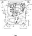
FIG. 4 is an explanatory diagram showing a case where thedrive unit 100 of the present embodiment is mounted on the vehicle. - In
FIG. 4 , threemount brackets 101 are fixed to thedrive unit 100, and thedrive unit 100 is supported by asuspension member 110 via themount brackets 101. Themount brackets 101 are provided at two locations on a front side in a vehicle front-rear direction of thedrive unit 100 and at both ends in a vehicle width direction, and at one location on a rear side in the vehicle front-rear direction of thedrive unit 100 and at a center in the vehicle width direction. - With such a configuration, the
drive unit 100 is disposed such that the center of gravity thereof is located approximately at a center of a triangle connecting the positions of the threemount brackets 101. Thesuspension member 110 supporting thedrive unit 100 is fixed to a vehicle body. - As shown in
FIG. 1 , thebrushes 5 are arranged in a V-shape on one side (left side in the drawing, vehicle rear side) of therotor shaft 11 in thebrush holder 15. Therefore, the brushholder accommodating portion 20 is disposed at a position biased to the vehicle rear side (one side) with respect to therotor shaft 11. - On the other hand, among the
mount brackets 101 to which thedrive unit 100 is fixed, themount bracket 101 fixed to a right side surface (first cover 21 side) of thedrive unit 100 is disposed on a vehicle front side (one side) with respect to therotor shaft 11. - With such a configuration, while the
mount bracket 101 is disposed at a most suitable position in thedrive unit 100, themount bracket 101 does not interfere when thesecond cover 22 is opened or closed and when thebrush holder 15 is attached or detached during maintenance or replacement of thebrush holder 15. - The bus
bar accommodating portion 25 is disposed above the other side of the brushholder accommodating portion 20, that is, above the vehicle front side with respect to therotor shaft 11. By disposing the brushholder accommodating portion 20 at the position biased to the vehicle rear side with respect to therotor shaft 11, a sufficient space is generated to dispose the three-phase bus bar 41 above the vehicle front side. - By disposing the three-
phase bus bar 41 above therotor shaft 11, theinverter unit 3 can be disposed above the rotatingelectric machine 1 and integrally with the rotatingelectric machine 1. Since the rotatingelectric machine 1 includes the stator and the rotor in thehousing 2 having high rigidity, theinverter unit 3 is protected by the rotatingelectric machine 1 having high rigidity and a case is prevented from being broken even at the time of a collision, for example. - As described above, the present embodiment is applied to the rotating
electric machine 1 including thebrush holder 15 that holds thebrushes 5. The rotatingelectric machine 1 includes thehousing 2 including thefirst cover 21 through which therotor shaft 11 passes. The brushholder accommodating portion 20 that accommodates thebrush holder 15 is recessed in thefirst cover 21 in the axial direction from the outer side of thefirst cover 21. Thebrush holder 15 is disposed in the brushholder accommodating portion 20 such that the distance (A) between thelower surface 15a of thebrush holder 15 and the innerperipheral wall 20a of the brushholder accommodating portion 20 facing thelower surface 15a is larger than the distance between the anotherperipheral surface 15b of thebrush holder 15 and the another innerperipheral wall 20b of the brushholder accommodating portion 20 facing the anotherperipheral surface 15b. - With such a configuration, the abrasion
powder accumulation portion 29 having a sufficient capacity to accumulate the abrasion powder can be provided below thebrush holder 15. The abrasion powder of thebrush 5 is accumulated in the abrasionpowder accumulation portion 29. Accordingly, even when the abrasion powder of the brush is accumulated in the abrasionpowder accumulation portion 29, the insulation distance between thebrush 5 and the housing 2 (and the first cover 21) can be maintained. In this way, it is possible to prevent the deterioration in the insulation property between thebrush 5 and thehousing 2. - In the present embodiment, the space surrounded by the
lower surface 15a of thebrush holder 15, the innerperipheral wall 20a of the brushholder accommodating portion 20, thefirst cover 21, and thesecond cover 22 is configured as the abrasionpowder accumulation portion 29 in which the abrasion powder of thebrushes 5 is accumulated. - With such a configuration, even when the brush
holder accommodating portion 20 that accommodates thebrush holder 15 has a sealed structure, a space capable of sufficiently accumulating the abrasion powder of thebrush 5 can be provided. - In the present embodiment, the
brush holder 15 holds thebrushes 5 such that thebrushes 5 come into contact with therotor shaft 11 from one side of therotor shaft 11. - With such a configuration, the
brush 5 comes into contact with theslip ring 12 of therotor shaft 11 from the vehicle rear side (one side), so that thebrush holder 15 can be disposed at a position biased to the vehicle rear side with respect to therotor shaft 11. Accordingly, an area occupied by thebrush holder 15 in thefirst cover 21 can be minimized. - In the present embodiment, the
rotor shaft 11 is provided with a plurality of electrodes (slip rings 12) at positions separated from each other in the axial direction, and thebrush holder 15 holds thebrushes 5 such that one pair ofbrushes 5 comes into contact with one electrode (positive electrode) and another pair ofbrushes 5 comes into contact with another one electrode (negative electrode). - With such a configuration, even when the
rotor shaft 11 is provided with the plurality of electrodes (slip rings 12) as the positive electrode and the negative electrode, thebrush holder 15 can be disposed at the position biased to the vehicle rear side with respect to therotor shaft 11 by bringing the pair ofbrushes 5 into contact with the each of the slip rings 12 from the vehicle rear side (one side) in a V-shape. - In the present embodiment, the bus
bar accommodating portion 25 that accommodates the three-phase bus bar 41 electrically connected to the rotatingelectric machine 1 is recessed in thefirst cover 21 in the axial direction. In thefirst cover 21, the brushholder accommodating portion 20 is disposed at a position biased to the vehicle rear side with respect to therotor shaft 11, and the busbar accommodating portion 25 is disposed above the brushholder accommodating portion 20. - With such a configuration, by disposing the
brush holder 15 at the position biased to the one side of therotor shaft 11, it is possible to secure a sufficient space for disposing, on an upper portion of therotor shaft 11, the busbar accommodating portion 25 that accommodates the three-phase bus bar 41. Accordingly, theinverter unit 3 and the rotatingelectric machine 1 can be disposed close to each other, and thus theinverter unit 3 is protected by the rotatingelectric machine 1 having high rigidity and a case is prevented from being broken even at the time of a collision, for example. - In the present embodiment, the rotating
electric machine 1 is supported by the vehicle body via thesuspension member 110, themount bracket 101 configured to connect the rotatingelectric machine 1 and thesuspension member 110 is provided on the outer side of thefirst cover 21, and themount bracket 101 is disposed at a position biased to the vehicle front side with respect to therotor shaft 11 and the brushholder accommodating portion 20. - With such a configuration, since the brush
holder accommodating portion 20 is disposed at the position biased to the vehicle rear side with respect to therotor shaft 11, themount bracket 101 fixed to the side surface of thedrive unit 100 can be disposed at the vehicle front side with respect to therotor shaft 11, which is an optimum position with respect to thedrive unit 100. Accordingly, themount bracket 101 supporting the rotatingelectric machine 1 can be disposed at an appropriate position while not interfering with opening and closing of thesecond cover 22 covering the brushholder accommodating portion 20. - In the present embodiment, the
brush holder 15 is disposed in the brushholder accommodating portion 20 such that the distance between theupper surface 15c of thebrush holder 15 and the innerperipheral wall 20c of the brushholder accommodating portion 20 facing theupper surface 15c is smaller than the distance between the anotherperipheral surface 15b of thebrush holder 15 and the another innerperipheral wall 20b of the brushholder accommodating portion 20 facing the anotherperipheral surface 15b. - With such a configuration, by disposing the
brush holder 15 as close to an upper side as possible in the brushholder accommodating portion 20, the distance between thelower surface 15a of thebrush holder 15 and the innerperipheral wall 20a of the brushholder accommodating portion 20 can be increased. - Although the embodiment and modifications of the present invention have been described above, the above embodiment and modifications are merely a part of application examples of the present invention, and do not mean that the technical scope of the present invention is limited to the specific configurations of the above embodiment.
- The present invention shows a winding field type electric motor as the rotating
electric machine 1, but is not limited thereto, and can be applied to a rotating electric machine having a brush (DC motor, induction motor, or the like).
Claims (7)
- A rotating electric machine, comprising:a brush holder that holds brushes; anda housing including a first cover through which a rotor shaft passes, whereina brush holder accommodating portion that accommodates the brush holder is recessed in the first cover in an axial direction from an outer side of the first cover, andthe brush holder is disposed in the brush holder accommodating portion such that a distance between a lower surface of the brush holder and an inner peripheral wall of the brush holder accommodating portion facing the lower surface is larger than a distance between another peripheral surface of the brush holder and an inner peripheral wall of the brush holder accommodating portion facing the another peripheral surface.
- The rotating electric machine according to claim 1, further comprising:a second cover that covers the brush holder accommodating portion, whereina space surrounded by the lower surface of the brush holder, the inner peripheral wall of the brush holder accommodating portion, the first cover, and the second cover is configured as an abrasion powder accumulation portion in which abrasion powder of the brushes is accumulated.
- The rotating electric machine according to claim 1 or 2, wherein
the brush holder holds the brushes such that the brushes come into contact with the rotor shaft from one side of the rotor shaft orthogonal to the axial direction. - The rotating electric machine according to claim 3, whereinthe rotor shaft is provided with a plurality of electrodes at positions separated from each other in the axial direction, andthe brush holder holds the brushes such that one pair of the brushes comes into contact with one of the electrodes and another pair of the brushes comes into contact with another one of the electrodes.
- The rotating electric machine according to claim 3 or 4, whereina bus bar accommodating portion that accommodates a tip end of a three-phase bus bar electrically connected to the rotating electric machine is recessed in the first cover in the axial direction from the outer side of the first cover, andin the first cover, the bus bar accommodating portion is disposed above the brush holder accommodating portion.
- The rotating electric machine according to any one of claims 3 to 5, whereinthe rotating electric machine is to be supported by a vehicle body via a suspension member,a mount bracket configured to connect the rotating electric machine and the suspension member is provided on the outer side of the first cover, andthe mount bracket is disposed at a position biased to a vehicle front side with respect to the brush holder accommodating portion in a vehicle front-rear direction.
- The rotating electric machine according to any one of claims 1 to 6, wherein
the brush holder is disposed in the brush holder accommodating portion such that a distance between an upper surface of the brush holder and an inner peripheral wall of the brush holder accommodating portion facing the upper surface is smaller than a distance between another surface of the brush holder and another inner peripheral wall of the brush holder accommodating portion facing the another surface.
Applications Claiming Priority (1)
| Application Number | Priority Date | Filing Date | Title |
|---|---|---|---|
| PCT/JP2022/002711 WO2023144893A1 (en) | 2022-01-25 | 2022-01-25 | Rotating electric machine |
Publications (3)
| Publication Number | Publication Date |
|---|---|
| EP4472037A1 true EP4472037A1 (en) | 2024-12-04 |
| EP4472037A4 EP4472037A4 (en) | 2025-04-09 |
| EP4472037B1 EP4472037B1 (en) | 2026-04-08 |
Family
ID=87471168
Family Applications (1)
| Application Number | Title | Priority Date | Filing Date |
|---|---|---|---|
| EP22923762.3A Active EP4472037B1 (en) | 2022-01-25 | 2022-01-25 | Rotating electric machine |
Country Status (5)
| Country | Link |
|---|---|
| US (1) | US12348105B2 (en) |
| EP (1) | EP4472037B1 (en) |
| JP (1) | JP7729409B2 (en) |
| CN (1) | CN118575395A (en) |
| WO (1) | WO2023144893A1 (en) |
Family Cites Families (17)
| Publication number | Priority date | Publication date | Assignee | Title |
|---|---|---|---|---|
| US20030155836A1 (en) * | 1985-07-31 | 2003-08-21 | Shigenori Uda | Small-size motor |
| JP2871003B2 (en) | 1990-06-26 | 1999-03-17 | 松下電工株式会社 | Commutator motor brush |
| JPH0621377U (en) | 1992-08-18 | 1994-03-18 | 株式会社日立ビルシステムサービス | Winding type induction motor current collector |
| JP3508854B2 (en) * | 2000-11-30 | 2004-03-22 | 株式会社デンソー | Rotating electric machine |
| JP4265571B2 (en) * | 2005-06-01 | 2009-05-20 | 株式会社デンソー | Vehicle alternator |
| JP4556808B2 (en) * | 2005-08-23 | 2010-10-06 | 株式会社デンソー | Vehicle alternator |
| US7615908B2 (en) * | 2006-09-11 | 2009-11-10 | Denso Corporation | Vehicle alternator with improved operation reliability |
| JP4565345B2 (en) | 2006-09-11 | 2010-10-20 | 株式会社デンソー | Vehicle alternator |
| DE102008002030A1 (en) * | 2007-09-17 | 2009-03-19 | Robert Bosch Gmbh | Commutation device and electric machine |
| CN102976187A (en) * | 2011-09-02 | 2013-03-20 | 上海三菱电梯有限公司 | Traction machine for elevator |
| JP6293476B2 (en) * | 2013-04-22 | 2018-03-14 | アスモ株式会社 | motor |
| JP2016197930A (en) * | 2013-09-17 | 2016-11-24 | パナソニックIpマネジメント株式会社 | Brush motor |
| JP6243812B2 (en) * | 2014-07-24 | 2017-12-06 | 株式会社豊田自動織機 | Rotating electric machine |
| JP6883961B2 (en) | 2016-08-18 | 2021-06-09 | キヤノンメディカルシステムズ株式会社 | X-ray computed tomography equipment |
| CN205901536U (en) * | 2016-08-19 | 2017-01-18 | 西安泰富西玛电机有限公司 | Wire winding type slip -ring motor with ventilation structure |
| WO2020105501A1 (en) * | 2018-11-22 | 2020-05-28 | パナソニックIpマネジメント株式会社 | Motor and brush housing part |
| CN116608896B (en) * | 2023-06-30 | 2023-09-19 | 常州华旋传感技术有限公司 | Motor-integrated rotary transformer simulation equipment and simulation method thereof |
-
2022
- 2022-01-25 JP JP2023576293A patent/JP7729409B2/en active Active
- 2022-01-25 US US18/832,781 patent/US12348105B2/en active Active
- 2022-01-25 EP EP22923762.3A patent/EP4472037B1/en active Active
- 2022-01-25 WO PCT/JP2022/002711 patent/WO2023144893A1/en not_active Ceased
- 2022-01-25 CN CN202280089652.XA patent/CN118575395A/en active Pending
Also Published As
| Publication number | Publication date |
|---|---|
| JP7729409B2 (en) | 2025-08-26 |
| US20250132629A1 (en) | 2025-04-24 |
| EP4472037A4 (en) | 2025-04-09 |
| EP4472037B1 (en) | 2026-04-08 |
| WO2023144893A1 (en) | 2023-08-03 |
| CN118575395A (en) | 2024-08-30 |
| US12348105B2 (en) | 2025-07-01 |
| JPWO2023144893A1 (en) | 2023-08-03 |
Similar Documents
| Publication | Publication Date | Title |
|---|---|---|
| CN204013086U (en) | Rotating electrical machines and vehicles | |
| CA2630182C (en) | Assembly for an electric machine | |
| CN105515281B (en) | The electric machine of vehicle | |
| EP2623394B1 (en) | Electric power steering apparatus and control device integrated type electric motor | |
| US8633620B2 (en) | Electric motor, in particular actuator motor or drive motor in motor vehicles | |
| CN109196745B (en) | Handheld power tool with disconnect switch | |
| CN114844295B (en) | electric vehicles | |
| CN116073589A (en) | drive unit | |
| CN105317655A (en) | Electric compressor | |
| US7952242B2 (en) | Rotary electric machine integrated with control device | |
| US20210362289A1 (en) | Electric work machine | |
| US20170317557A1 (en) | Controller Integrated Rotating Electrical Machine | |
| JP2015019550A (en) | Terminal box for EV vehicles equipped with in-wheel motors | |
| EP4472037A1 (en) | Rotating electric machine | |
| CN114628965B (en) | Electric device | |
| CN114640210A (en) | Rotating electrical machine with integrated controller | |
| CN114629286B (en) | Rotary electric machine unit | |
| EP4648981A1 (en) | A hub motor assembly | |
| JP7371705B2 (en) | rotating machine | |
| US20220416616A1 (en) | Rotating electric machine | |
| JP3775621B2 (en) | High voltage component built-in rotary electric machine | |
| JP6881692B1 (en) | Cooling structure of rotary electric machine | |
| US11949288B2 (en) | Wheel drive device and electric vehicle provided with the same | |
| WO2025120741A1 (en) | Rotating electrical machine | |
| JP4609445B2 (en) | AC generator for vehicles |
Legal Events
| Date | Code | Title | Description |
|---|---|---|---|
| STAA | Information on the status of an ep patent application or granted ep patent |
Free format text: STATUS: THE INTERNATIONAL PUBLICATION HAS BEEN MADE |
|
| PUAI | Public reference made under article 153(3) epc to a published international application that has entered the european phase |
Free format text: ORIGINAL CODE: 0009012 |
|
| STAA | Information on the status of an ep patent application or granted ep patent |
Free format text: STATUS: REQUEST FOR EXAMINATION WAS MADE |
|
| 17P | Request for examination filed |
Effective date: 20240725 |
|
| AK | Designated contracting states |
Kind code of ref document: A1 Designated state(s): AL AT BE BG CH CY CZ DE DK EE ES FI FR GB GR HR HU IE IS IT LI LT LU LV MC MK MT NL NO PL PT RO RS SE SI SK SM TR |
|
| A4 | Supplementary search report drawn up and despatched |
Effective date: 20250312 |
|
| RIC1 | Information provided on ipc code assigned before grant |
Ipc: H02K 23/00 20060101ALI20250306BHEP Ipc: H02K 13/00 20060101ALI20250306BHEP Ipc: H02K 5/00 20060101AFI20250306BHEP |
|
| DAV | Request for validation of the european patent (deleted) | ||
| DAX | Request for extension of the european patent (deleted) | ||
| STAA | Information on the status of an ep patent application or granted ep patent |
Free format text: STATUS: EXAMINATION IS IN PROGRESS |
|
| 17Q | First examination report despatched |
Effective date: 20250929 |
|
| GRAP | Despatch of communication of intention to grant a patent |
Free format text: ORIGINAL CODE: EPIDOSNIGR1 |
|
| STAA | Information on the status of an ep patent application or granted ep patent |
Free format text: STATUS: GRANT OF PATENT IS INTENDED |
|
| GRAS | Grant fee paid |
Free format text: ORIGINAL CODE: EPIDOSNIGR3 |
|
| GRAA | (expected) grant |
Free format text: ORIGINAL CODE: 0009210 |
|
| STAA | Information on the status of an ep patent application or granted ep patent |
Free format text: STATUS: THE PATENT HAS BEEN GRANTED |
|
| INTG | Intention to grant announced |
Effective date: 20260218 |
|
| AK | Designated contracting states |
Kind code of ref document: B1 Designated state(s): AL AT BE BG CH CY CZ DE DK EE ES FI FR GB GR HR HU IE IS IT LI LT LU LV MC MK MT NL NO PL PT RO RS SE SI SK SM TR |
|
| REG | Reference to a national code |
Ref country code: CH Ref legal event code: F10 Free format text: ST27 STATUS EVENT CODE: U-0-0-F10-F00 (AS PROVIDED BY THE NATIONAL OFFICE) Effective date: 20260408 Ref country code: GB Ref legal event code: FG4D |
|
| REG | Reference to a national code |
Ref country code: DE Ref legal event code: R096 Ref document number: 602022034366 Country of ref document: DE |