EP4472034A1 - Motor having cooling structure - Google Patents
Motor having cooling structure Download PDFInfo
- Publication number
- EP4472034A1 EP4472034A1 EP23213651.5A EP23213651A EP4472034A1 EP 4472034 A1 EP4472034 A1 EP 4472034A1 EP 23213651 A EP23213651 A EP 23213651A EP 4472034 A1 EP4472034 A1 EP 4472034A1
- Authority
- EP
- European Patent Office
- Prior art keywords
- outlet
- motor
- refrigerant
- coil
- rotor
- Prior art date
- Legal status (The legal status is an assumption and is not a legal conclusion. Google has not performed a legal analysis and makes no representation as to the accuracy of the status listed.)
- Pending
Links
- 238000001816 cooling Methods 0.000 title claims abstract description 34
- 239000003507 refrigerant Substances 0.000 claims abstract description 106
- 230000004308 accommodation Effects 0.000 claims abstract description 29
- 239000007788 liquid Substances 0.000 claims description 7
- 239000004020 conductor Substances 0.000 claims description 5
- IJGRMHOSHXDMSA-UHFFFAOYSA-N Atomic nitrogen Chemical compound N#N IJGRMHOSHXDMSA-UHFFFAOYSA-N 0.000 claims description 4
- 230000003993 interaction Effects 0.000 claims description 3
- 239000001257 hydrogen Substances 0.000 claims description 2
- 229910052739 hydrogen Inorganic materials 0.000 claims description 2
- 229910052757 nitrogen Inorganic materials 0.000 claims description 2
- UFHFLCQGNIYNRP-UHFFFAOYSA-N Hydrogen Chemical compound [H][H] UFHFLCQGNIYNRP-UHFFFAOYSA-N 0.000 claims 1
- 230000008901 benefit Effects 0.000 description 4
- 230000007423 decrease Effects 0.000 description 3
- 239000007789 gas Substances 0.000 description 3
- 238000000034 method Methods 0.000 description 3
- 230000004048 modification Effects 0.000 description 3
- 238000012986 modification Methods 0.000 description 3
- 239000007921 spray Substances 0.000 description 3
- 238000005507 spraying Methods 0.000 description 2
- 230000001360 synchronised effect Effects 0.000 description 2
- 241001465754 Metazoa Species 0.000 description 1
- 230000001154 acute effect Effects 0.000 description 1
- 239000000498 cooling water Substances 0.000 description 1
- 230000008878 coupling Effects 0.000 description 1
- 238000010168 coupling process Methods 0.000 description 1
- 238000005859 coupling reaction Methods 0.000 description 1
- 238000010586 diagram Methods 0.000 description 1
- 238000007599 discharging Methods 0.000 description 1
- 230000005672 electromagnetic field Effects 0.000 description 1
- 230000020169 heat generation Effects 0.000 description 1
- 239000001307 helium Substances 0.000 description 1
- 229910052734 helium Inorganic materials 0.000 description 1
- SWQJXJOGLNCZEY-UHFFFAOYSA-N helium atom Chemical compound [He] SWQJXJOGLNCZEY-UHFFFAOYSA-N 0.000 description 1
- 125000004435 hydrogen atom Chemical class [H]* 0.000 description 1
- 230000006872 improvement Effects 0.000 description 1
- 229910052754 neon Inorganic materials 0.000 description 1
- GKAOGPIIYCISHV-UHFFFAOYSA-N neon atom Chemical compound [Ne] GKAOGPIIYCISHV-UHFFFAOYSA-N 0.000 description 1
- 230000004044 response Effects 0.000 description 1
- 238000006467 substitution reaction Methods 0.000 description 1
- 230000008016 vaporization Effects 0.000 description 1
- 238000009834 vaporization Methods 0.000 description 1
- XLYOFNOQVPJJNP-UHFFFAOYSA-N water Substances O XLYOFNOQVPJJNP-UHFFFAOYSA-N 0.000 description 1
Images




Classifications
-
- H—ELECTRICITY
- H02—GENERATION; CONVERSION OR DISTRIBUTION OF ELECTRIC POWER
- H02K—DYNAMO-ELECTRIC MACHINES
- H02K1/00—Details of the magnetic circuit
- H02K1/06—Details of the magnetic circuit characterised by the shape, form or construction
- H02K1/22—Rotating parts of the magnetic circuit
- H02K1/32—Rotating parts of the magnetic circuit with channels or ducts for flow of cooling medium
-
- H—ELECTRICITY
- H02—GENERATION; CONVERSION OR DISTRIBUTION OF ELECTRIC POWER
- H02K—DYNAMO-ELECTRIC MACHINES
- H02K9/00—Arrangements for cooling or ventilating
- H02K9/19—Arrangements for cooling or ventilating for machines with closed casing and closed-circuit cooling using a liquid cooling medium, e.g. oil
- H02K9/193—Arrangements for cooling or ventilating for machines with closed casing and closed-circuit cooling using a liquid cooling medium, e.g. oil with provision for replenishing the cooling medium; with means for preventing leakage of the cooling medium
-
- H—ELECTRICITY
- H02—GENERATION; CONVERSION OR DISTRIBUTION OF ELECTRIC POWER
- H02K—DYNAMO-ELECTRIC MACHINES
- H02K3/00—Details of windings
- H02K3/04—Windings characterised by the conductor shape, form or construction, e.g. with bar conductors
- H02K3/24—Windings characterised by the conductor shape, form or construction, e.g. with bar conductors with channels or ducts for cooling medium between the conductors
-
- H—ELECTRICITY
- H02—GENERATION; CONVERSION OR DISTRIBUTION OF ELECTRIC POWER
- H02K—DYNAMO-ELECTRIC MACHINES
- H02K7/00—Arrangements for handling mechanical energy structurally associated with dynamo-electric machines, e.g. structural association with mechanical driving motors or auxiliary dynamo-electric machines
- H02K7/003—Couplings; Details of shafts
-
- H—ELECTRICITY
- H02—GENERATION; CONVERSION OR DISTRIBUTION OF ELECTRIC POWER
- H02K—DYNAMO-ELECTRIC MACHINES
- H02K9/00—Arrangements for cooling or ventilating
- H02K9/14—Arrangements for cooling or ventilating wherein gaseous cooling medium circulates between the machine casing and a surrounding mantle
- H02K9/16—Arrangements for cooling or ventilating wherein gaseous cooling medium circulates between the machine casing and a surrounding mantle wherein the cooling medium circulates through ducts or tubes within the casing
-
- H—ELECTRICITY
- H02—GENERATION; CONVERSION OR DISTRIBUTION OF ELECTRIC POWER
- H02K—DYNAMO-ELECTRIC MACHINES
- H02K9/00—Arrangements for cooling or ventilating
- H02K9/19—Arrangements for cooling or ventilating for machines with closed casing and closed-circuit cooling using a liquid cooling medium, e.g. oil
-
- H—ELECTRICITY
- H02—GENERATION; CONVERSION OR DISTRIBUTION OF ELECTRIC POWER
- H02K—DYNAMO-ELECTRIC MACHINES
- H02K9/00—Arrangements for cooling or ventilating
- H02K9/19—Arrangements for cooling or ventilating for machines with closed casing and closed-circuit cooling using a liquid cooling medium, e.g. oil
- H02K9/20—Arrangements for cooling or ventilating for machines with closed casing and closed-circuit cooling using a liquid cooling medium, e.g. oil wherein the cooling medium vaporises within the machine casing
-
- H—ELECTRICITY
- H02—GENERATION; CONVERSION OR DISTRIBUTION OF ELECTRIC POWER
- H02K—DYNAMO-ELECTRIC MACHINES
- H02K9/00—Arrangements for cooling or ventilating
- H02K9/22—Arrangements for cooling or ventilating by solid heat conducting material embedded in, or arranged in contact with, the stator or rotor, e.g. heat bridges
- H02K9/225—Heat pipes
-
- H—ELECTRICITY
- H02—GENERATION; CONVERSION OR DISTRIBUTION OF ELECTRIC POWER
- H02K—DYNAMO-ELECTRIC MACHINES
- H02K2205/00—Specific aspects not provided for in the other groups of this subclass relating to casings, enclosures, supports
- H02K2205/09—Machines characterised by drain passages or by venting, breathing or pressure compensating means
-
- H—ELECTRICITY
- H02—GENERATION; CONVERSION OR DISTRIBUTION OF ELECTRIC POWER
- H02K—DYNAMO-ELECTRIC MACHINES
- H02K55/00—Dynamo-electric machines having windings operating at cryogenic temperatures
- H02K55/02—Dynamo-electric machines having windings operating at cryogenic temperatures of the synchronous type
-
- Y—GENERAL TAGGING OF NEW TECHNOLOGICAL DEVELOPMENTS; GENERAL TAGGING OF CROSS-SECTIONAL TECHNOLOGIES SPANNING OVER SEVERAL SECTIONS OF THE IPC; TECHNICAL SUBJECTS COVERED BY FORMER USPC CROSS-REFERENCE ART COLLECTIONS [XRACs] AND DIGESTS
- Y10—TECHNICAL SUBJECTS COVERED BY FORMER USPC
- Y10S—TECHNICAL SUBJECTS COVERED BY FORMER USPC CROSS-REFERENCE ART COLLECTIONS [XRACs] AND DIGESTS
- Y10S505/00—Superconductor technology: apparatus, material, process
- Y10S505/825—Apparatus per se, device per se, or process of making or operating same
- Y10S505/873—Active solid-state device
- Y10S505/875—Combined with housing and cryogenic fluid cooling
Definitions
- the present disclosure relates to a motor having a cooling structure, and more particularly, to a motor having a cooling structure for cooling a coil using a refrigerant.
- Electric vehicles or hybrid vehicles may be driven by a motor obtaining rotational force with battery power.
- Such a motor may include parts for power, such as a permanent magnet, a core, and a coil. These parts may cause considerable heat due to electrical resistance or the like if the motor operates.
- the motor may include a stator with a coil disposed on an inner side thereof.
- the motor may further include a rotor at least partially surrounded by the coil.
- the motor may further include a shaft which may be connected to the rotor to rotate integrally with the rotor.
- the motor may further include a pipe which may be at least partially inserted into the shaft and through which a refrigerant for cooling the coil may flow. The pipe may rotate integrally with the rotor and the shaft.
- Terms, such as ⁇ first,' 'second,' etc., may be used to describe various components, but the components are not to be construed as being limited to the terms. The terms are used only to distinguish one component from another component.
- the 'first' component may be named the ⁇ second' component and the 'second' component may also be similarly named the 'first' component, without departing from the scope of the present disclosure.
- the term "and/or" includes any and all combinations of one or more of the associated listed items
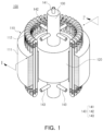
- An example motor 100 will be described with reference to FIGS. 1 to 3 and 4A to 4C .
- FIG. 1 is a perspective view of an example motor 100.
- FIG. 1 is a view in which a portion of a stator 110 is cut to show a structure in which a rotor 120 is disposed inside the stator 110 of the motor 100.
- the motor 100 may be used in aircraft or vehicle, and may generate driving force by converting electrical energy into mechanical energy through an electromagnetic field.
- Aircraft may refer to a mobility vehicle that may move by flying in the sky. That is, aircraft may include a vehicle that may land on the ground or a basin using landing gear after flight, as well as referring to rotary wing aircraft, drones, tilt rotor aircraft, vertical take-off and landing aircraft, and fixed-wing aircraft. Also, aircraft may include manned aircraft and unmanned aircraft. Manned aircraft may include a body capable of operating autonomously, as well as a body controlled by a pilot.
- Vehicles may include an electric vehicle (EV) or a hybrid electric vehicle (HEV).
- EV electric vehicle
- HEV hybrid electric vehicle
- vehicles refer to various vehicles that move objects to be transported, such as people, animals, or objects, from a starting point to a destination. These vehicles are not limited to vehicles that drive on roads or tracks.
- the motor 100 may include the stator 110, the rotor 120, a shaft 130, and a pipe 140.
- the stator 110 may include a stator core 111 and a coil 112.
- the coil 112 may be wound around a portion (e.g., a tooth portion (not shown)) of the stator core 111.
- the rotor 120 may be disposed inside the stator 110.
- the rotor 120 may rotate at the center of the motor 100.
- the rotor 120 may be disposed inside the stator 110.
- a circumferential outer surface of the rotor 120 may be surrounded by the stator 110.
- the rotor 120 may be configured such that a permanent magnet (not shown) is inserted or attached therein.
- the motor 100 may be referred to as a permanent magnet synchronous motor (PMSM) in which a permanent magnet is embedded (or inserted) into the rotor 120.
- PMSM permanent magnet synchronous motor
- the rotor 120 may be driven to rotate based on an electromagnetic interaction generated between the coil 112 and the permanent magnet.
- the shaft 130 may rotate together with the rotor 120.
- the shaft 130 may transmit power based on rotation of the rotor 120 to the outside. If the rotor 120 rotates, the shaft 130 may be integrally coupled to the rotor 120 to be rotatable together with the rotor 120. For example, the shaft 130 may penetrate the center of the rotor 120 in a longitudinal direction of the shaft 130 to be coupled.
- the pipe 140 may provide a refrigerant movement path for cooling the coil 112.
- the pipe 140 may have a hollow shape to enable inflow, movement, and/or outflow of the refrigerant.
- the pipe 140 may be coupled to the shaft 130.
- the pipe 140 may be inserted or embedded in the shaft 130 to move integrally with the shaft 130.
- the pipe 140 may rotate together with the shaft 130 if the shaft 130 rotates.
- the pipe 140 may have a heat insulating structure. According to the present disclosure, by cooling the coil 112 using a cryogenic refrigerant, the cooling performance of the motor 100 is increased to reduce the size of the motor 100 and improve the specific power density and performance of the motor 100.
- cryogenic refrigerant may include, but is not limited to, liquid hydrogen, liquid nitrogen, liquid helium, and/or neon gas.
- cryogenic temperatures may refer to very low temperatures, for example, equal to or lower than -150 °C (absolute temperature 123K).
- the pipe 140 may include an inlet 141, a first outlet 142 extending from one side of the inlet 141, and a second outlet 143 extending from the other side of the inlet 141. A portion of each of the inlet 141, the second outlet 143, and the second outlet 143 may penetrate the outer circumferential surface of the shaft 130 and protrude to the outside of the shaft 130. One or more of the first outlet 142 and the second outlet 143 may be formed. The configuration of the pipe 140 will be described in more detail with reference to FIGS. 2 and 3 below.
- the motor 100 may further include a housing (e.g., a housing 150 of FIG. 2 ) accommodating the rotor 120, the stator 110, the shaft 130, and the pipe 140, and forming the exterior of the motor 100.
- the housing may have a storage space formed therein to surround other components of the motor 100.
- the inside of the housing may be in a vacuum state.
- the motor 100 may be configured such that the pipe 140 is inserted into the shaft 130 and integrally coupled thereto and a refrigerant flows in through the pipe 140 and/or moves to flow out to the coil 112 to cool the coil 112.
- the pipe 140 may be inserted into the shaft 130 and the pipe 140 may penetrate through the shaft 130 to protrude from the outer circumferential surface of the shaft 130.
- the shaft 130 may include an upper end portion 131 and a lower end portion 132, and the pipe 140 may protrude from the upper end portion 131 of the shaft 130.
- the shaft 130 may rotate together with the rotor 120 about an axis of rotation R.
- a portion of the pipe 140 may be inserted into the shaft 130 and another portion thereof may protrude out of the shaft 130 so that the refrigerant flows in and out, while the pipe 140 rotates together with the shaft 130.
- the pipe 140 may include an inlet 141 through which the refrigerant flows in and outlets 142 and 143 through which the refrigerant flows out.
- the inlet 141 and the outlets 142 and 143 may communicate with each other so that the refrigerant may move.
- each of the inlet 141 and the outlet 142, 143 has a hollow shape, and a flow path through which the refrigerant may move may be formed therein, and a flow path of the inlet 141 and flow paths of the outlet 142 and 143 may be connected to each other.
- the outlets 142 and 143 of the pipe 140 may include a first outlet 142 and a second outlet 143 respectively corresponding to both end portions 112a and 112b of the coil 112.
- the first outlet 142 may be located to be adjacent to the first end portion 112a of the coil 112 and spray the refrigerant to the first end portion 112a and the periphery of the first end portion 112a.
- the second outlet 143 may be located to be adjacent to the second end portion 112b of the coil 112 and may spray the refrigerant to the second end portion 112b and the periphery of the second end portion 112b.
- the inlet 141 of the pipe 140 may extend from the outside of the shaft 130 to the inside of the shaft 130 through the upper end portion 131 of the shaft 130.
- the inlet 141 may have a shape with one side open.
- the inlet 141 may have an inlet hole 141a formed at an upper end portion so that a refrigerant may flow in therethrough and a lower end portion which is blocked.
- a portion of the inlet 141 in which the inlet hole 141a is formed may protrude from the upper end portion 131 of the shaft 130 and be exposed to the outside of the shaft 130.
- the first outlet 142 of the pipe 140 may be disposed to correspond to the first end portion 112a of the coil 112 and may extend from one side (e.g., an upper portion) of the inlet 141.
- a first outlet hole 142a may be formed in the first outlet 142 so that the refrigerant may be sprayed toward the first end portion 112a of the coil 112.
- a portion of the first outlet 142 in which the first outlet hole 142a is formed may protrude from the outer surface of the shaft 130 and be exposed to the outside of the shaft 130.
- One or more first outlets 142 may be configured.
- the second outlet 143 of the pipe 140 may be disposed to correspond to the second end portion 112b of the coil 112 and may extend from the other side (e.g., a lower portion) of the inlet 141.
- a second outlet hole 143a may be formed in the second outlet 143 so that the refrigerant may be sprayed toward the second end portion 112b of the coil 112.
- a portion of the second outlet 143 in which the second outlet hole 143a is formed may protrude from the outer surface of the shaft 130 and be exposed to the outside of the shaft 130.
- One or more second outlets 142 may be configured.
- the pipe 140 may be connected to a refrigerant tank in which the refrigerant is stored.
- the inlet 141 of the pipe 140 may be connected to the refrigerant tank to allow the refrigerant to flow in from the refrigerant tank.
- the inlet 141 of the pipe 140 may be rotatably connected to the refrigerant tank. If the pipe 140 rotates together with the shaft 130, the pipe 140 may be connected to rotate with respect to the refrigerant tank.
- the inlet 141 of the pipe 140 may communicate with the refrigerant tank by using a ball bearing structure or the like, and may be rotatably connected to the relatively fixed refrigerant tank.
- the refrigerant may flow into the inlet 141 by pressure of the refrigerant tank and move to the outlets 142 and 143.
- the method of moving the refrigerant based on the pressure of the refrigerant tank is an example, and according to additional or alternative examples, the refrigerant may be introduced using a pump.
- the housing 150 may be configured to maintain vacuum therein, and a discharge hole (not shown) through which the refrigerant sprayed through the outlets 142 and 143 is discharged may be formed in the housing 150.
- the motor 100 may further include a separate device for maintaining vacuum inside the housing 150 in which the discharge hole is formed.
- the cryogenic refrigerant sprayed through the pipe 140 may be directly sprayed to the coil 112 to cool the coil.
- the cryogenic refrigerant is a liquid
- the liquid cryogenic refrigerant may be vaporized while coming into contact with the coil having high temperatures, and gas generated due to vaporization may be discharged to the outside of the housing 150 through the discharge hole.
- first outlets 142 and four second outlets 143 may be formed equally and extend from the inlet 141 in a direction perpendicular to the axis of rotation R from the inlet 141, but the shape of the pipe 140 is not limited thereto.
- the number of first outlets 142 and second outlets 143 may be changed in consideration of the performance of the motor 100 and/or the type of refrigerant, and the first outlet 142 and the second outlet 143 may be formed in different numbers.
- the first outlet 142 and/or the second outlet 143 may form an obtuse angle or an acute angle that is not perpendicular to the axis of rotation R.
- the inlet 141, the first outlet 142, and the second outlet 143 may partially penetrate the shaft 130 and protrude from the shaft 130, but the shape of the pipe 140 is not limited thereto.
- the pipe 140 may be variously modified within a range in which the inlet hole 141a, the first outlet hole 142a, and the second outlet hole 143a communicate with the outside of the shaft 130 to allow the refrigerant to flow in and out.
- the inlet hole 141a, the first outlet hole 142a, and the second outlet hole 143a may be formed to have a circular shape, but are not limited thereto. According to additional or alternative examples, the inlet hole 141a, the first outlet hole 142a, and the second outlet hole 143a may be changed into various polygonal shapes, and the inlet hole 141a, and the first outlet hole 142a, and the second outlet hole 143a may be formed to have different shapes.
- the refrigerant flows into the inlet 141, moves to the first outlet 142 and the second outlet 143, and then flows out through the first outlet hole 142a and the second outlet hole 143a toward the first end portion 112a and the second end portion 112b of the coil 112, respectively, to cool the coil 112.
- the pipe 140 and the rotor 120 may rotate together, the refrigerant flowing out from the first outlet 142 and the second outlet 143 may be scattered by centrifugal force in the circumferential direction to be smoothly sprayed onto the entire coil 112 surrounding the rotor 120. Through this, the cooling efficiency of the coil 112 may be increased.
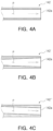
- FIGS. 4A, 4B and 4C are cross-sectional views of the outlet 142 of the motor 100.
- FIGS. 4A, 4B and 4C are diagrams illustrating various modifications of a flow path P through which the refrigerant moves in the first outlet 142, in which FIGS. 4A, 4B and 4C illustrate cross-sections of the first outlets 142, 142', and 142" having flow paths P having different shapes in a length direction.
- the arrows denoted by the dotted lines in FIGS. 4A, 4B and 4C indicate directions in which the refrigerant flows out.
- the shapes of the flow paths will be described based on the first outlets 142, 142', and 142", but this may also be equally applied to the second outlet (e.g., the second outlet 143 of FIGS. 1 to 3 ).
- the flow path P may have a constant cross-sectional area and be formed in a shape parallel to a direction in which the first outlet 142 extends.
- an inner wall of the first outlet 142 forming the flow path P may be parallel to an outer wall of the first outlet 142.
- the flow path P may be formed in a shape in which a cross-sectional area increases toward the first outlet hole 142a.
- the cross-sectional area of the flow path P may gradually increase from a region connected to the inlet (e.g., the inlet 141 of FIGS. 1 to 3 ) toward the first outlet hole 142a.
- the present disclosure is not limited thereto, and the flow path P may be formed in a shape in which the cross-sectional area decreases toward the first outlet hole 142a, contrary to FIG. 4B .
- the flow path P may have a constant cross-sectional area and be formed in a shape inclined at a predetermined angle.
- an inner wall of the first outlet 142" forming the flow path P may form a predetermined angle with an outer wall of the first outlet 142".
- An inclination direction of the flow path P may be determined based on a rotation direction of a motor (e.g., the motor 100 of FIGS. 1 to 3 ).
- the flow path P having an inclined shape may be applied if the motor 100 rotates in one direction, but is not limited thereto.
- the flow path P may be formed in an inclined shape in which the cross-sectional area increases or decreases.
- the size and/or shape of the flow path P of the first outlets 142, 142', and 142" and the first outlet hole 142a may be designed considering various factors, such as the amount of heat generated by the motor 100, a quality of the refrigerant, and the required degree of spray of refrigerant.
- Another example motor 200 will be described with reference to FIGS. 5 to 7 .
- FIG. 5 is a perspective view of the motor 200.
- FIG. 5 is a view in which a portion of a stator 210 is cut to show a structure in which a rotor 220 is disposed inside the stator 210 of the motor 200.
- the motor 200 of FIG. 5 is different from the configuration of the motor 100(e.g., the motor 100 of FIGS. 1 to 3 ) in which the refrigerant flows out through the outlet (e.g., the outlets 142 and 143 of FIGS. 1 to 3 ) of the pipe (e.g., the pipe 140 of FIGS. 1 to 3 ), in that the refrigerant flows out from the rotor 220 by utilizing the rotor 220 as a refrigerant tank, and the other configuration thereof may be the same as or similar to that which is described in reference to the motor 100.
- the other configuration thereof may be the same as or similar to that which is described in reference to the motor 100.
- a description overlapping with the previous description will be omitted and differences will mainly be described.
- the motor 200 may include the stator 210, the rotor 220, a shaft 230, and a pipe 240. Since the configuration of the stator 210 (the stator core 211 and the coil 212) and the configuration of the shaft 230 are the same as those described above with reference to FIGS. 1 to 3 , a description thereof will be omitted.
- the rotor 220 may store or accommodate a refrigerant therein, and may discharge the refrigerant located therein externally based on rotation according to driving of the motor 200.
- a predetermined space in which the refrigerant may be accommodated may be formed inside the rotor 220.
- Outlet holes 221 and 222 through which refrigerant flows out may be formed on a side surface of the rotor 220.
- the outlet holes 221 and 222 may penetrate the side surface of the rotor 220.
- the outlet holes 221 and 222 may include a first outlet hole 221 formed to be adjacent to one end portion of the rotor 220 and a second outlet hole 222 formed to be adjacent to the other end portion of the rotor 220.
- Each of the first outlet hole 221 and the second outlet hole 222 may be formed as one or more outlet holes.
- the configuration of the rotor 220 will be described in more detail with reference to FIGS. 6 and 7 below.
- the pipe 240 may be inserted into the shaft 230.
- the pipe 240 may be have a hollow shape to enable the inflow, movement, and/or outflow of the refrigerant, and both ends thereof may be open.
- the refrigerant may flow in through the pipe 240 and be accommodated in a space inside the rotor 220.
- the pipe 240 may rotate together with the shaft 230 or may be connected to the shaft 230 so as to be separated from rotation of the shaft 230.
- the motor 200 may be different from the motor 100 in that the pipe 240 is separated from the rotation of the shaft 230.
- the pipe 240 may be rotatably connected to a refrigerant tank.
- the pipe 240 may be connected to the refrigerant tank by using a ball bearing structure to rotate with respect to the refrigerant tank if rotating together with the shaft 230.
- FIG. 6 is a cross-sectional view of the motor 200 illustrated in FIG. 5 .
- FIG. 7 is a view illustrating the rotor 220, the shaft 230, and the pipe 240 of the motor 200 illustrated in FIG. 5 .
- FIG. 6 is a cross-sectional view taken along line II-II' of FIG. 5
- FIG. 7 is a view illustrating a coupling structure between the rotor 220, the shaft 230, and the pipe 240.
- FIG. 7 is a view schematically illustrating a housing 250 accommodating other components (e.g., the stator 210, the rotor 220, the shaft 230, and/or the pipe 240) of the motor 200 and/or the pipe 240.
- other components e.g., the stator 210, the rotor 220, the shaft 230, and/or the pipe 240
- the motor 200 may be configured such that the refrigerant is accommodated (or stored) in the rotor 220 and the refrigerant flows out to the coil 212 through outlet holes 221 and 222 formed in the rotor 220 to cool the coil 212.
- an upper side or an upper portion indicates a direction in which the pipe 240 protrudes from the shaft 230
- a lower side or a lower portion indicates a direction opposite to the upper side or the upper portion.
- the pipe 240 may be inserted into the shaft 230.
- the shaft 230 may include an upper end portion 231 and a lower end portion 232, and a portion of the pipe 240 having an inlet hole 241 may protrude from the upper end portion 231 of the shaft 230.
- the depiction is an example, and the pipe 240 may be changed into various shapes within a range in which the inlet hole 241 formed at the upper end communicates with the outside of the shaft 230 to allow the refrigerant to flow in.
- An accommodation space 223 in which the refrigerant is accommodated may be formed in the rotor 220.
- a permanent magnet (not shown) may be provided in the rotor 220, and the accommodation space 223 may be formed to avoid the permanent magnet.
- the accommodation space 223 may communicate with the pipe 240 so that the refrigerant may be introduced from the pipe 240.
- the refrigerant introduced into the pipe 240 may move to the accommodation space 223 through a connection passage (not shown) communicatively connecting the pipe 240 to the accommodation space 223.
- the configuration for the connection between the accommodation space 223 and the pipe 240 is not limited to the example described above.
- FIG. 6 schematically illustrates the accommodation space 223 of the rotor 220, and the shapes of the rotor 220 and the accommodation space 223 are not limited to the illustrated examples.
- a first outlet hole 221 and a second outlet hole 222 may be formed on a side surface of the rotor 220.
- the side surface refers to a surface of the rotor 220 facing in a direction, perpendicular to the axis of rotation R.
- the first outlet hole 221 and the second outlet hole 222 may penetrate the side surface of the rotor 220 toward the coil 212.
- the first outlet hole 221 and the second outlet hole 222 communicate with the accommodation space 223 to discharge the refrigerant accommodated in the accommodation space 223 to the outside of the rotor 220.
- the length of the rotor 220 in a vertical direction may correspond to the length of the coil 220 in the vertical direction in order to form the first outlet hole 221 and the second outlet hole 222 in positions adjacent to both end portions of the coil 212.
- the first outlet hole 221 may be formed to correspond to the first end portion 212a of the coil 212.
- the first outlet hole 221 may be formed on a side surface adjacent to an upper end portion of the rotor 220.
- the first outlet hole 221 may be formed toward the first end portion 212a of the coil 212, and the refrigerant may be sprayed to the first end portion 212a through the first outlet hole 221.
- One or more first outlet holes 221 may be configured.
- the first outlet hole 221 may include a plurality of holes spaced apart from each other at predetermined intervals along the side surface of the rotor 220.
- the second outlet hole 222 may be formed to correspond to the second end portion 212b of the coil 212.
- the second outlet hole 222 may be formed on a side surface adjacent to the lower end portion of the rotor 220.
- the second outlet hole 222 may be formed toward the second end portion 212b of the coil 212, and the refrigerant may be sprayed to the second end portion 212b through the second outlet hole 222.
- One or more second outlet holes 222 may be configured.
- the second outlet hole 222 may include a plurality of holes spaced apart from each other at predetermined intervals along the side surface of the rotor 220.
- the first outlet hole 221 and the second outlet hole 222 may be formed in a circular shape, but are not limited thereto. According to additional or alternative examples, the first outlet hole 221 and the second outlet hole 222 may be changed to have various polygonal shapes, and the first outlet hole 221 and the second outlet hole 222 may be formed to have different shapes. Also, the first outlet hole 221 and the second outlet hole 222 may be formed to have different sizes.
- the pipe 240 is configured to communicate with the accommodation space 223 of the rotor 220 via the shaft 230 while being inserted into the shaft 230, but is not limited thereto.
- the pipe 240 may be variously modified within a range in which the refrigerant moves to the accommodation space 223 of the rotor 220 through the pipe 240, such that the pipe 240 is directly connected to the accommodation space 223 of the rotor 22, rather than being inserted into the shaft 230.
- the refrigerant may flow out toward the first end portion 212a and the second end portion 212b of the coil 212 respectively through the first outlet hole 221 and the second outlet hole 222 to cool the coil 212.
- the refrigerant flowing out from the first outlet hole 221 and the second outlet hole 222 is scattered by centrifugal force in the circumferential direction, the refrigerant may be smoothly sprayed to the entire coil 212 surrounding the rotor 220. Through this, the cooling efficiency of the coil 212 may be increased.
- cooling performance may be improved and motor efficiency may be increased by cooling the coil using a cryogenic refrigerant.
- the size of the motor may be reduced in response to the improvement of cooling performance, thereby reducing costs and improving power density.
- the cooling structure of the motor may be simplified without a pressure pump.
- the motor 10 may be provided with a cooling structure capable of reducing heat in order to prevent damage to the motor and a decrease in efficiency due to heat generation. Additionally the cooling structures may ensure continuous and stable operations of the motor.
- Methods for cooling a motor include an air cooling method using air, a water cooling method using cooling water, and an oil cooling method using oil. As the performance of motors has improved, the cooling performance should also be secured, so a direct cooling method using oil has been applied.
- Examples herein describe a motor having a cooling structure capable of cooling a coil of the motor by utilizing a cryogenic refrigerant to improve the cooling performance of the motor.
- Examples herein also provide a cooling structure capable of spraying a refrigerant by using pressure of a refrigerant gas or centrifugal force according to rotation of a motor, even without a separate pressure pump for providing a refrigerant.
- a motor includes a stator with a coil disposed on an inner side thereof, a rotor at least partially surrounded by the coil, a shaft connected to the rotor to rotate integrally with the rotor, and a pipe at least partially inserted into the shaft and through which a refrigerant for cooling the coil flows, wherein the pipe rotates integrally with the rotor and the shaft.
- the pipe may include an inlet into which the refrigerant flows from the outside and an outlet connected to the inlet and discharging the refrigerant toward the coil.
- the outlet may be formed in positions corresponding to both end portions of the coil.
- the outlet may include a first outlet corresponding to an upper end portion of the coil and a second outlet corresponding to a lower end portion of the coil, and each of the first outlet and the second outlet may be formed as one or more outlets.
- a magnet or a conductor bar may be disposed inside the rotor, the rotor rotates about an axis of rotation based on electromagnetic interaction between the magnet or the conductor bar and the coil, and the inlet may extend parallel to the axis of rotation, and the first outlet and the second outlet extend, perpendicular to the axis of rotation from the inlet.
- An inlet hole communicating with a refrigerant tank supplying the refrigerant may be formed in the inlet, and a first outlet hole and a second outlet hole communicating with the inlet hole may be formed in the first outlet and the second outlet, respectively.
- the inlet hole, the first outlet hole, and the second outlet hole may be exposed to the outside of the shaft and communicate with the outside of the shaft.
- the inlet may be inserted into the shaft through an upper end portion of the shaft, and the first outlet and the second outlet may protrude from the outer surface of the shaft through the shaft.
- the inlet hole, the first outlet hole, and the second outlet hole may have a circular or polygonal shape.
- a flow path for the refrigerant to flow therethrough may be formed inside the outlet, and the flow path may include at least one of a shape with a constant cross-sectional area, a shape with a variable cross-sectional area, or an inclined shape.
- a motor includes a stator with a coil disposed on an inner side thereof, a rotor at least partially surrounded by the coil and having an accommodation space in which a refrigerant for cooling the coil is accommodated, a shaft connected to the rotor to rotate integrally with the rotor, and a pipe communicating with the accommodation space so that the refrigerant is introduced from an external source and the refrigerant flows into the accommodation space therethrough.
- the rotor may have an outlet hole communicating with the accommodation space on an outer surface thereof, and the refrigerant accommodated in the accommodation space may flow out to the coil through the outlet hole.
- the outlet hole may be formed in positions corresponding to both ends of the coil.
- the outlet hole may include a first outlet hole corresponding to an upper end portion of the coil and a second outlet hole corresponding to a lower end portion of the coil, and each of the first outlet hole and the second outlet hole may be formed as one or more outlet holes.
- the refrigerant accommodated in the accommodation space may be sprayed toward the coil from the outlet hole based on centrifugal force generated by rotation of the rotor.
- the outlet hole may include at least one of a shape with a constant cross-sectional area, a shape with a variable cross-sectional area, or an inclined shape based on a thickness direction of the rotor.
Landscapes
- Engineering & Computer Science (AREA)
- Power Engineering (AREA)
- Motor Or Generator Cooling System (AREA)
Abstract
Description
- This application claims the benefit of
Korean Patent Application No. 10-2023-0071792 filed on June 2, 2023 - The present disclosure relates to a motor having a cooling structure, and more particularly, to a motor having a cooling structure for cooling a coil using a refrigerant.
- Electric vehicles or hybrid vehicles may be driven by a motor obtaining rotational force with battery power.
- Such a motor may include parts for power, such as a permanent magnet, a core, and a coil. These parts may cause considerable heat due to electrical resistance or the like if the motor operates.
- The following summary presents a simplified summary of certain features. The summary is not an extensive overview and is not intended to identify key or critical elements.
- Systems, apparatuses, and methods are described for a motor. The motor may include a stator with a coil disposed on an inner side thereof. The motor may further include a rotor at least partially surrounded by the coil. The motor may further include a shaft which may be connected to the rotor to rotate integrally with the rotor. The motor may further include a pipe which may be at least partially inserted into the shaft and through which a refrigerant for cooling the coil may flow. The pipe may rotate integrally with the rotor and the shaft.
- These and other features and advantages are described below.
- The above and other aspects, features, and advantages of the present disclosure will be more clearly understood from the following detailed description, taken in conjunction with the accompanying drawings, in which:
-
FIG. 1 is a perspective view of an example motor; -
FIG. 2 is a cross-sectional view of the example motor illustrated inFIG. 1 ; -
FIG. 3 is a view illustrating a shaft and a pipe of the example motor illustrated inFIG. 1 ; -
FIGS. 4A, 4B and 4C are cross-sectional views of an outlet of an example motor; -
FIG. 5 is a perspective view of another example motor; -
FIG. 6 is a cross-sectional view of the example motor illustrated inFIG. 5 ; and -
FIG. 7 is a view illustrating a rotor, a shaft and a pipe of the example motor illustrated inFIG. 5 . - The present disclosure may be modified variably and may have various exemplary aspects, particular examples of which will be illustrated in drawings and described in detail. However, it is to be understood that the present disclosure is not limited to a specific disclosed form, but includes all modifications, equivalents, and substitutions without departing from the scope and spirit of the present disclosure.
- Terms, such as `first,' 'second,' etc., may be used to describe various components, but the components are not to be construed as being limited to the terms. The terms are used only to distinguish one component from another component. For example, the 'first' component may be named the `second' component and the 'second' component may also be similarly named the 'first' component, without departing from the scope of the present disclosure. As used here, the term "and/or" includes any and all combinations of one or more of the associated listed items
- Terms used in the present specification are used only in order to describe specific example aspects rather than limiting the present disclosure. Singular forms are intended to include plural forms unless the context clearly indicates otherwise. It will be further understood that the terms "comprises" or "have" used in this specification, specify the presence of stated features, steps, operations, components, parts, or a combination thereof, but do not preclude the presence or addition of one or more other features, numerals, steps, operations, components, parts, or a combination thereof.
- Hereinafter, examples in the present disclosure will be described with reference to the drawings.
- An
example motor 100 will be described with reference toFIGS. 1 to 3 and4A to 4C . -
FIG. 1 is a perspective view of anexample motor 100. For example,FIG. 1 is a view in which a portion of astator 110 is cut to show a structure in which arotor 120 is disposed inside thestator 110 of themotor 100. - Referring to
FIG. 1 , the motor 100may be used in aircraft or vehicle, and may generate driving force by converting electrical energy into mechanical energy through an electromagnetic field. Aircraft may refer to a mobility vehicle that may move by flying in the sky. That is, aircraft may include a vehicle that may land on the ground or a basin using landing gear after flight, as well as referring to rotary wing aircraft, drones, tilt rotor aircraft, vertical take-off and landing aircraft, and fixed-wing aircraft. Also, aircraft may include manned aircraft and unmanned aircraft. Manned aircraft may include a body capable of operating autonomously, as well as a body controlled by a pilot. - Vehicles may include an electric vehicle (EV) or a hybrid electric vehicle (HEV). However, vehicles refer to various vehicles that move objects to be transported, such as people, animals, or objects, from a starting point to a destination. These vehicles are not limited to vehicles that drive on roads or tracks.
- The motor 100may include the
stator 110, therotor 120, ashaft 130, and apipe 140. - The
stator 110 may include astator core 111 and acoil 112. Thecoil 112 may be wound around a portion (e.g., a tooth portion (not shown)) of thestator core 111. Therotor 120 may be disposed inside thestator 110. - The
rotor 120 may rotate at the center of themotor 100. Therotor 120 may be disposed inside thestator 110. For example, a circumferential outer surface of therotor 120 may be surrounded by thestator 110. Therotor 120 may be configured such that a permanent magnet (not shown) is inserted or attached therein. For example, themotor 100 may be referred to as a permanent magnet synchronous motor (PMSM) in which a permanent magnet is embedded (or inserted) into therotor 120. As power is applied to thecoil 112 of thestator 110, therotor 120 may be driven to rotate based on an electromagnetic interaction generated between thecoil 112 and the permanent magnet. However, themotor 100 of the present disclosure is not limited to the above example, and may be referred to as various types of motors including a synchronous reluctance motor (SynRM). For example, an electromagnet or a conductor bar may be disposed on therotor 120. Also, for another example, therotor 120 may be configured as a salient pole rotor. - The
shaft 130 may rotate together with therotor 120. Theshaft 130 may transmit power based on rotation of therotor 120 to the outside. If therotor 120 rotates, theshaft 130 may be integrally coupled to therotor 120 to be rotatable together with therotor 120. For example, theshaft 130 may penetrate the center of therotor 120 in a longitudinal direction of theshaft 130 to be coupled. - The
pipe 140 may provide a refrigerant movement path for cooling thecoil 112. Thepipe 140 may have a hollow shape to enable inflow, movement, and/or outflow of the refrigerant. Thepipe 140 may be coupled to theshaft 130. Thepipe 140 may be inserted or embedded in theshaft 130 to move integrally with theshaft 130. For example, thepipe 140 may rotate together with theshaft 130 if theshaft 130 rotates. Thepipe 140 may have a heat insulating structure. According to the present disclosure, by cooling thecoil 112 using a cryogenic refrigerant, the cooling performance of themotor 100 is increased to reduce the size of themotor 100 and improve the specific power density and performance of themotor 100. For example, the cryogenic refrigerant may include, but is not limited to, liquid hydrogen, liquid nitrogen, liquid helium, and/or neon gas. In general, cryogenic temperatures may refer to very low temperatures, for example, equal to or lower than -150 °C (absolute temperature 123K). - The
pipe 140 may include aninlet 141, afirst outlet 142 extending from one side of theinlet 141, and asecond outlet 143 extending from the other side of theinlet 141. A portion of each of theinlet 141, thesecond outlet 143, and thesecond outlet 143 may penetrate the outer circumferential surface of theshaft 130 and protrude to the outside of theshaft 130. One or more of thefirst outlet 142 and thesecond outlet 143 may be formed. The configuration of thepipe 140 will be described in more detail with reference toFIGS. 2 and3 below. - Although not shown, the
motor 100 may further include a housing (e.g., ahousing 150 ofFIG. 2 ) accommodating therotor 120, thestator 110, theshaft 130, and thepipe 140, and forming the exterior of themotor 100. For example, the housing may have a storage space formed therein to surround other components of themotor 100. The inside of the housing may be in a vacuum state. -
FIG. 2 is a cross-sectional view of themotor 100 illustrated inFIG. 1 .FIG. 3 is a view illustrating theshaft 130 and thepipe 140 of themotor 100 illustrated inFIG. 1 . For example,FIG. 2 is a cross-sectional view taken along the line I-I' ofFIG. 1 , andFIG. 3 is a view illustrating a structure in which thepipe 140 is inserted into theshaft 130 and coupled thereto.FIG. 2 is a schematic view of thehousing 150 accommodating other parts (e.g., thestator 110, therotor 120, theshaft 130, and/or the pipe 140) of themotor 100. - Referring to
FIGS. 2 and3 , themotor 100 may be configured such that thepipe 140 is inserted into theshaft 130 and integrally coupled thereto and a refrigerant flows in through thepipe 140 and/or moves to flow out to thecoil 112 to cool thecoil 112. - Hereinafter, in the description of
FIGS. 2 and3 , the upper side or upper portion indicates a direction in which theinlet 141 of thepipe 140 protrudes from theshaft 130, and the lower side or lower portion indicates the opposite direction to the upper side or upper portion. - The
stator 110 may be configured in a shape in which a plurality ofcoils 112 are arranged on thestator core 111. For example, the plurality ofcoils 112 may be fixedly arranged along the inner circumferential surface of thestator core 111. Bothend portions coil 112 may be exposed to the outside of thestator core 111. For example, thecoil 112 may include afirst end portion 112a facing upwardly and asecond end portion 112b facing downwardly. In the present disclosure, a region adjacent to bothend portions coil 112 may be exposed to the outside of thestator core 111 in order to cool thecoil 112 by directly spraying a refrigerant to thecoil 112. - The
pipe 140 may be inserted into theshaft 130 and thepipe 140 may penetrate through theshaft 130 to protrude from the outer circumferential surface of theshaft 130. Theshaft 130 may include anupper end portion 131 and alower end portion 132, and thepipe 140 may protrude from theupper end portion 131 of theshaft 130. Theshaft 130 may rotate together with therotor 120 about an axis of rotation R. - A portion of the
pipe 140 may be inserted into theshaft 130 and another portion thereof may protrude out of theshaft 130 so that the refrigerant flows in and out, while thepipe 140 rotates together with theshaft 130. Thepipe 140 may include aninlet 141 through which the refrigerant flows in andoutlets inlet 141 and theoutlets inlet 141 and theoutlet inlet 141 and flow paths of theoutlet outlets pipe 140 may include afirst outlet 142 and asecond outlet 143 respectively corresponding to bothend portions coil 112. For example, thefirst outlet 142 may be located to be adjacent to thefirst end portion 112a of thecoil 112 and spray the refrigerant to thefirst end portion 112a and the periphery of thefirst end portion 112a. Thesecond outlet 143 may be located to be adjacent to thesecond end portion 112b of thecoil 112 and may spray the refrigerant to thesecond end portion 112b and the periphery of thesecond end portion 112b. - The
inlet 141 of thepipe 140 may extend from the outside of theshaft 130 to the inside of theshaft 130 through theupper end portion 131 of theshaft 130. Theinlet 141 may have a shape with one side open. For example, theinlet 141 may have aninlet hole 141a formed at an upper end portion so that a refrigerant may flow in therethrough and a lower end portion which is blocked. A portion of theinlet 141 in which theinlet hole 141a is formed may protrude from theupper end portion 131 of theshaft 130 and be exposed to the outside of theshaft 130. - The
first outlet 142 of thepipe 140 may be disposed to correspond to thefirst end portion 112a of thecoil 112 and may extend from one side (e.g., an upper portion) of theinlet 141. Afirst outlet hole 142a may be formed in thefirst outlet 142 so that the refrigerant may be sprayed toward thefirst end portion 112a of thecoil 112. A portion of thefirst outlet 142 in which thefirst outlet hole 142a is formed may protrude from the outer surface of theshaft 130 and be exposed to the outside of theshaft 130. One or morefirst outlets 142 may be configured. - The
second outlet 143 of thepipe 140 may be disposed to correspond to thesecond end portion 112b of thecoil 112 and may extend from the other side (e.g., a lower portion) of theinlet 141. Asecond outlet hole 143a may be formed in thesecond outlet 143 so that the refrigerant may be sprayed toward thesecond end portion 112b of thecoil 112. A portion of thesecond outlet 143 in which thesecond outlet hole 143a is formed may protrude from the outer surface of theshaft 130 and be exposed to the outside of theshaft 130. One or moresecond outlets 142 may be configured. - The
pipe 140 may be connected to a refrigerant tank in which the refrigerant is stored. For example, theinlet 141 of thepipe 140 may be connected to the refrigerant tank to allow the refrigerant to flow in from the refrigerant tank. Theinlet 141 of thepipe 140 may be rotatably connected to the refrigerant tank. If thepipe 140 rotates together with theshaft 130, thepipe 140 may be connected to rotate with respect to the refrigerant tank. For example, theinlet 141 of thepipe 140 may communicate with the refrigerant tank by using a ball bearing structure or the like, and may be rotatably connected to the relatively fixed refrigerant tank. The refrigerant may flow into theinlet 141 by pressure of the refrigerant tank and move to theoutlets - The
housing 150 may be configured to maintain vacuum therein, and a discharge hole (not shown) through which the refrigerant sprayed through theoutlets housing 150. For example, themotor 100 may further include a separate device for maintaining vacuum inside thehousing 150 in which the discharge hole is formed. The cryogenic refrigerant sprayed through thepipe 140 may be directly sprayed to thecoil 112 to cool the coil. For example, if the cryogenic refrigerant is a liquid, the liquid cryogenic refrigerant may be vaporized while coming into contact with the coil having high temperatures, and gas generated due to vaporization may be discharged to the outside of thehousing 150 through the discharge hole. - As illustrated in
FIGS. 2 and3 , fourfirst outlets 142 and foursecond outlets 143 may be formed equally and extend from theinlet 141 in a direction perpendicular to the axis of rotation R from theinlet 141, but the shape of thepipe 140 is not limited thereto. According to additional or alternative examples, the number offirst outlets 142 andsecond outlets 143 may be changed in consideration of the performance of themotor 100 and/or the type of refrigerant, and thefirst outlet 142 and thesecond outlet 143 may be formed in different numbers. In addition, thefirst outlet 142 and/or thesecond outlet 143 may form an obtuse angle or an acute angle that is not perpendicular to the axis of rotation R. - As illustrated in
FIGS. 2 and3 , theinlet 141, thefirst outlet 142, and thesecond outlet 143 may partially penetrate theshaft 130 and protrude from theshaft 130, but the shape of thepipe 140 is not limited thereto. According to additional or alternative examples, thepipe 140 may be variously modified within a range in which theinlet hole 141a, thefirst outlet hole 142a, and thesecond outlet hole 143a communicate with the outside of theshaft 130 to allow the refrigerant to flow in and out. - As illustrated in
FIGS. 2 and3 , theinlet hole 141a, thefirst outlet hole 142a, and thesecond outlet hole 143a may be formed to have a circular shape, but are not limited thereto. According to additional or alternative examples, theinlet hole 141a, thefirst outlet hole 142a, and thesecond outlet hole 143a may be changed into various polygonal shapes, and theinlet hole 141a, and thefirst outlet hole 142a, and thesecond outlet hole 143a may be formed to have different shapes. - According to the coil cooling method according to the
motor 100, the refrigerant flows into theinlet 141, moves to thefirst outlet 142 and thesecond outlet 143, and then flows out through thefirst outlet hole 142a and thesecond outlet hole 143a toward thefirst end portion 112a and thesecond end portion 112b of thecoil 112, respectively, to cool thecoil 112. In addition, if therotor 120 rotates, thepipe 140 and therotor 120 may rotate together, the refrigerant flowing out from thefirst outlet 142 and thesecond outlet 143 may be scattered by centrifugal force in the circumferential direction to be smoothly sprayed onto theentire coil 112 surrounding therotor 120. Through this, the cooling efficiency of thecoil 112 may be increased. -
FIGS. 4A, 4B and 4C are cross-sectional views of theoutlet 142 of themotor 100. For example,FIGS. 4A, 4B and 4C are diagrams illustrating various modifications of a flow path P through which the refrigerant moves in thefirst outlet 142, in whichFIGS. 4A, 4B and 4C illustrate cross-sections of thefirst outlets FIGS. 4A, 4B and 4C indicate directions in which the refrigerant flows out. - Hereinafter, the shapes of the flow paths will be described based on the
first outlets second outlet 143 ofFIGS. 1 to 3 ). - Referring to
FIGS. 4A, 4B and 4C , thefirst outlets - According to the
first outlet 142 illustrated inFIG. 4A , the flow path P may have a constant cross-sectional area and be formed in a shape parallel to a direction in which thefirst outlet 142 extends. For example, an inner wall of thefirst outlet 142 forming the flow path P may be parallel to an outer wall of thefirst outlet 142. - According to the first outlet 142' illustrated in
FIG. 4B , the flow path P may be formed in a shape in which a cross-sectional area increases toward thefirst outlet hole 142a. For example, the cross-sectional area of the flow path P may gradually increase from a region connected to the inlet (e.g., theinlet 141 ofFIGS. 1 to 3 ) toward thefirst outlet hole 142a. However, the present disclosure is not limited thereto, and the flow path P may be formed in a shape in which the cross-sectional area decreases toward thefirst outlet hole 142a, contrary toFIG. 4B . - According to the
first outlet 142" illustrated inFIG. 4C , the flow path P may have a constant cross-sectional area and be formed in a shape inclined at a predetermined angle. For example, an inner wall of thefirst outlet 142" forming the flow path P may form a predetermined angle with an outer wall of thefirst outlet 142". An inclination direction of the flow path P may be determined based on a rotation direction of a motor (e.g., themotor 100 ofFIGS. 1 to 3 ). For example, the flow path P having an inclined shape may be applied if themotor 100 rotates in one direction, but is not limited thereto. Also or alternatively, the flow path P may be formed in an inclined shape in which the cross-sectional area increases or decreases. - The size and/or shape of the flow path P of the
first outlets first outlet hole 142a may be designed considering various factors, such as the amount of heat generated by themotor 100, a quality of the refrigerant, and the required degree of spray of refrigerant. - Another
example motor 200 will be described with reference toFIGS. 5 to 7 . -
FIG. 5 is a perspective view of themotor 200. For example,FIG. 5 is a view in which a portion of astator 210 is cut to show a structure in which arotor 220 is disposed inside thestator 210 of themotor 200. - The
motor 200 ofFIG. 5 is different from the configuration of the motor 100(e.g., themotor 100 ofFIGS. 1 to 3 ) in which the refrigerant flows out through the outlet (e.g., theoutlets FIGS. 1 to 3 ) of the pipe (e.g., thepipe 140 ofFIGS. 1 to 3 ), in that the refrigerant flows out from therotor 220 by utilizing therotor 220 as a refrigerant tank, and the other configuration thereof may be the same as or similar to that which is described in reference to themotor 100.
Hereinafter, a description overlapping with the previous description will be omitted and differences will mainly be described. - Referring to
FIG. 5 , themotor 200 may include thestator 210, therotor 220, ashaft 230, and apipe 240. Since the configuration of the stator 210 (thestator core 211 and the coil 212) and the configuration of theshaft 230 are the same as those described above with reference toFIGS. 1 to 3 , a description thereof will be omitted. - The
rotor 220 may store or accommodate a refrigerant therein, and may discharge the refrigerant located therein externally based on rotation according to driving of themotor 200. A predetermined space in which the refrigerant may be accommodated may be formed inside therotor 220. Outlet holes 221 and 222 through which refrigerant flows out may be formed on a side surface of therotor 220. For example, the outlet holes 221 and 222 may penetrate the side surface of therotor 220. The outlet holes 221 and 222 may include afirst outlet hole 221 formed to be adjacent to one end portion of therotor 220 and asecond outlet hole 222 formed to be adjacent to the other end portion of therotor 220. Each of thefirst outlet hole 221 and thesecond outlet hole 222 may be formed as one or more outlet holes. The configuration of therotor 220 will be described in more detail with reference toFIGS. 6 and7 below. - The
pipe 240 may be inserted into theshaft 230. Thepipe 240 may be have a hollow shape to enable the inflow, movement, and/or outflow of the refrigerant, and both ends thereof may be open. The refrigerant may flow in through thepipe 240 and be accommodated in a space inside therotor 220. Thepipe 240 may rotate together with theshaft 230 or may be connected to theshaft 230 so as to be separated from rotation of theshaft 230. For example, themotor 200 may be different from themotor 100 in that thepipe 240 is separated from the rotation of theshaft 230. If thepipe 240 is configured to rotate together with theshaft 230, thepipe 240 may be rotatably connected to a refrigerant tank. For example, thepipe 240 may be connected to the refrigerant tank by using a ball bearing structure to rotate with respect to the refrigerant tank if rotating together with theshaft 230. -
FIG. 6 is a cross-sectional view of themotor 200 illustrated inFIG. 5 .FIG. 7 is a view illustrating therotor 220, theshaft 230, and thepipe 240 of themotor 200 illustrated inFIG. 5 . For example,FIG. 6 is a cross-sectional view taken along line II-II' ofFIG. 5 , andFIG. 7 is a view illustrating a coupling structure between therotor 220, theshaft 230, and thepipe 240.FIG. 7 is a view schematically illustrating ahousing 250 accommodating other components (e.g., thestator 210, therotor 220, theshaft 230, and/or the pipe 240) of themotor 200 and/or thepipe 240. - Referring to
FIGS. 6 and7 , themotor 200 may be configured such that the refrigerant is accommodated (or stored) in therotor 220 and the refrigerant flows out to thecoil 212 through outlet holes 221 and 222 formed in therotor 220 to cool thecoil 212. - Hereinafter, in the description of
FIGS. 6 and7 , an upper side or an upper portion indicates a direction in which thepipe 240 protrudes from theshaft 230, and a lower side or a lower portion indicates a direction opposite to the upper side or the upper portion. - The
pipe 240 may be inserted into theshaft 230. Theshaft 230 may include anupper end portion 231 and a lower end portion 232, and a portion of thepipe 240 having an inlet hole 241 may protrude from theupper end portion 231 of theshaft 230. However, the depiction is an example, and thepipe 240 may be changed into various shapes within a range in which the inlet hole 241 formed at the upper end communicates with the outside of theshaft 230 to allow the refrigerant to flow in. - An accommodation space (e.g., a refrigerant chamber) 223 in which the refrigerant is accommodated may be formed in the
rotor 220. Although not shown, a permanent magnet (not shown) may be provided in therotor 220, and theaccommodation space 223 may be formed to avoid the permanent magnet. Theaccommodation space 223 may communicate with thepipe 240 so that the refrigerant may be introduced from thepipe 240. For example, the refrigerant introduced into thepipe 240 may move to theaccommodation space 223 through a connection passage (not shown) communicatively connecting thepipe 240 to theaccommodation space 223. The configuration for the connection between theaccommodation space 223 and thepipe 240 is not limited to the example described above.FIG. 6 schematically illustrates theaccommodation space 223 of therotor 220, and the shapes of therotor 220 and theaccommodation space 223 are not limited to the illustrated examples. - A
first outlet hole 221 and asecond outlet hole 222 may be formed on a side surface of therotor 220. Here, the side surface refers to a surface of therotor 220 facing in a direction, perpendicular to the axis of rotation R. For example, thefirst outlet hole 221 and thesecond outlet hole 222 may penetrate the side surface of therotor 220 toward thecoil 212. Thefirst outlet hole 221 and thesecond outlet hole 222 communicate with theaccommodation space 223 to discharge the refrigerant accommodated in theaccommodation space 223 to the outside of therotor 220. In themotor 200, the length of therotor 220 in a vertical direction may correspond to the length of thecoil 220 in the vertical direction in order to form thefirst outlet hole 221 and thesecond outlet hole 222 in positions adjacent to both end portions of thecoil 212. - The
first outlet hole 221 may be formed to correspond to thefirst end portion 212a of thecoil 212. Thefirst outlet hole 221 may be formed on a side surface adjacent to an upper end portion of therotor 220. Thefirst outlet hole 221 may be formed toward thefirst end portion 212a of thecoil 212, and the refrigerant may be sprayed to thefirst end portion 212a through thefirst outlet hole 221. One or more first outlet holes 221 may be configured. For example, thefirst outlet hole 221 may include a plurality of holes spaced apart from each other at predetermined intervals along the side surface of therotor 220. - The
second outlet hole 222 may be formed to correspond to thesecond end portion 212b of thecoil 212. Thesecond outlet hole 222 may be formed on a side surface adjacent to the lower end portion of therotor 220. Thesecond outlet hole 222 may be formed toward thesecond end portion 212b of thecoil 212, and the refrigerant may be sprayed to thesecond end portion 212b through thesecond outlet hole 222. One or more second outlet holes 222 may be configured. For example, thesecond outlet hole 222 may include a plurality of holes spaced apart from each other at predetermined intervals along the side surface of therotor 220. - As illustrated in
FIGS. 6 and7 , thefirst outlet hole 221 and thesecond outlet hole 222 may be formed in a circular shape, but are not limited thereto. According to additional or alternative examples, thefirst outlet hole 221 and thesecond outlet hole 222 may be changed to have various polygonal shapes, and thefirst outlet hole 221 and thesecond outlet hole 222 may be formed to have different shapes. Also, thefirst outlet hole 221 and thesecond outlet hole 222 may be formed to have different sizes. - As illustrated in
FIGS. 6 and7 , thepipe 240 is configured to communicate with theaccommodation space 223 of therotor 220 via theshaft 230 while being inserted into theshaft 230, but is not limited thereto. According to additional or alternative examples, thepipe 240 may be variously modified within a range in which the refrigerant moves to theaccommodation space 223 of therotor 220 through thepipe 240, such that thepipe 240 is directly connected to theaccommodation space 223 of the rotor 22, rather than being inserted into theshaft 230. - According to the coil cooling method according to the
motor 200, if therotor 220 rotates in a state in which the refrigerant is accommodated (stored) in theaccommodation space 223 of therotor 220 through thepipe 240, the refrigerant may flow out toward thefirst end portion 212a and thesecond end portion 212b of thecoil 212 respectively through thefirst outlet hole 221 and thesecond outlet hole 222 to cool thecoil 212. In addition, as the refrigerant flowing out from thefirst outlet hole 221 and thesecond outlet hole 222 is scattered by centrifugal force in the circumferential direction, the refrigerant may be smoothly sprayed to theentire coil 212 surrounding therotor 220. Through this, the cooling efficiency of thecoil 212 may be increased. - According to some example configurations, cooling performance may be improved and motor efficiency may be increased by cooling the coil using a cryogenic refrigerant.
- In addition, in some example configurations, the size of the motor may be reduced in response to the improvement of cooling performance, thereby reducing costs and improving power density.
- In addition, in some example configurations, since the refrigerant is sprayed by pressure of the refrigerant tank or by centrifugal force according to the rotation of the motor, the cooling structure of the motor may be simplified without a pressure pump.
- It may be appreciated that, among other advantages, the motor 10 may be provided with a cooling structure capable of reducing heat in order to prevent damage to the motor and a decrease in efficiency due to heat generation. Additionally the cooling structures may ensure continuous and stable operations of the motor.
- Methods for cooling a motor include an air cooling method using air, a water cooling method using cooling water, and an oil cooling method using oil. As the performance of motors has improved, the cooling performance should also be secured, so a direct cooling method using oil has been applied.
- However, in recent years, as miniaturization, high output, and high efficiency have been continuously required for motors, it is necessary to secure better cooling performance.
- Examples herein describe a motor having a cooling structure capable of cooling a coil of the motor by utilizing a cryogenic refrigerant to improve the cooling performance of the motor.
- Examples herein also provide a cooling structure capable of spraying a refrigerant by using pressure of a refrigerant gas or centrifugal force according to rotation of a motor, even without a separate pressure pump for providing a refrigerant.
- According to an example configuration, a motor includes a stator with a coil disposed on an inner side thereof, a rotor at least partially surrounded by the coil, a shaft connected to the rotor to rotate integrally with the rotor, and a pipe at least partially inserted into the shaft and through which a refrigerant for cooling the coil flows, wherein the pipe rotates integrally with the rotor and the shaft.
- The pipe may include an inlet into which the refrigerant flows from the outside and an outlet connected to the inlet and discharging the refrigerant toward the coil.
- The outlet may be formed in positions corresponding to both end portions of the coil.
- The outlet may include a first outlet corresponding to an upper end portion of the coil and a second outlet corresponding to a lower end portion of the coil, and each of the first outlet and the second outlet may be formed as one or more outlets.
- A magnet or a conductor bar may be disposed inside the rotor, the rotor rotates about an axis of rotation based on electromagnetic interaction between the magnet or the conductor bar and the coil, and the inlet may extend parallel to the axis of rotation, and the first outlet and the second outlet extend, perpendicular to the axis of rotation from the inlet.
- An inlet hole communicating with a refrigerant tank supplying the refrigerant may be formed in the inlet, and a first outlet hole and a second outlet hole communicating with the inlet hole may be formed in the first outlet and the second outlet, respectively.
- The inlet hole, the first outlet hole, and the second outlet hole may be exposed to the outside of the shaft and communicate with the outside of the shaft.
- The inlet may be inserted into the shaft through an upper end portion of the shaft, and the first outlet and the second outlet may protrude from the outer surface of the shaft through the shaft.
- The inlet hole, the first outlet hole, and the second outlet hole may have a circular or polygonal shape.
- A flow path for the refrigerant to flow therethrough may be formed inside the outlet, and the flow path may include at least one of a shape with a constant cross-sectional area, a shape with a variable cross-sectional area, or an inclined shape.
- According to an example configuration, a motor includes a stator with a coil disposed on an inner side thereof, a rotor at least partially surrounded by the coil and having an accommodation space in which a refrigerant for cooling the coil is accommodated, a shaft connected to the rotor to rotate integrally with the rotor, and a pipe communicating with the accommodation space so that the refrigerant is introduced from an external source and the refrigerant flows into the accommodation space therethrough.
- The rotor may have an outlet hole communicating with the accommodation space on an outer surface thereof, and the refrigerant accommodated in the accommodation space may flow out to the coil through the outlet hole.
- The outlet hole may be formed in positions corresponding to both ends of the coil.
- The outlet hole may include a first outlet hole corresponding to an upper end portion of the coil and a second outlet hole corresponding to a lower end portion of the coil, and each of the first outlet hole and the second outlet hole may be formed as one or more outlet holes.
- The refrigerant accommodated in the accommodation space may be sprayed toward the coil from the outlet hole based on centrifugal force generated by rotation of the rotor.
- The outlet hole may include at least one of a shape with a constant cross-sectional area, a shape with a variable cross-sectional area, or an inclined shape based on a thickness direction of the rotor.
- While examples of the present disclosure have been illustrated and described above, it will be apparent to those skilled in the art that modifications and variations could be made without departing from the scope of the present disclosure as defined by the appended claims.
Claims (15)
- A motor comprising:a stator with a coil disposed on an inner side thereof;a rotor at least partially surrounded by the coil;a shaft connected to the rotor to rotate integrally with the rotor; anda pipe at least partially inserted into the shaft and through which a refrigerant for cooling the coil flows,wherein the pipe rotates integrally with the rotor and the shaft.
- The motor of claim 1, wherein the pipe comprises an inlet into which the refrigerant flows from outside and an outlet connected to the inlet and configured to discharge the refrigerant toward the coil.
- The motor of claim 2, wherein the outlet is formed in positions corresponding to both a first end portion and a second end portion of the coil.
- The motor of claim 2 or 3, wherein the outlet comprises a first outlet corresponding to an upper end portion of the coil and a second outlet corresponding to a lower end portion of the coil, and each of the first outlet and the second outlet is formed as one or more outlets.
- The motor of claim 4, further comprising a magnet or a conductor bar disposed inside the rotor, wherein the rotor rotates about an axis of rotation based on electromagnetic interaction between the magnet or the conductor bar and the coil, and the inlet extends substantially parallel to the axis of rotation, and the first outlet and the second outlet extend substantially perpendicular to the axis of rotation from the inlet.
- The motor of claim 4 or 5, further comprising:an inlet hole formed in the inlet and configured to communicate with a refrigerant tank supplying the refrigerant; anda first outlet hole formed in the first outlet and a second outlet hole formed in the second outlet, wherein the first outlet hole and the second outlet hole are configured to communicate with the inlet hole.
- The motor of claim 6, wherein the inlet hole, the first outlet hole, and the second outlet hole are exposed to an outside of the shaft and communicate with the outside of the shaft.
- The motor of anyone of claims 4-7, wherein the inlet is inserted into the shaft through an upper end portion of the shaft, and the first outlet and the second outlet protrude from an outer surface of the shaft through the shaft.
- The motor of claim 6 or of anyone of claims 7 and 8 in combination with claim 6, wherein the inlet hole, the first outlet hole, and the second outlet hole have a circular or polygonal shape.
- The motor of anyone of claims 2-9, wherein a flow path for the refrigerant to flow therethrough is formed inside the outlet, and the flow path comprises at least one of a shape with a constant cross-sectional area, a shape with a variable cross-sectional area, or an inclined shape.
- The motor of anyone of claims 1-10, wherein the refrigerant is a cryogenic refrigerant comprising liquid nitrogen or liquid hydrogen.
- A motor comprising:a stator with a coil disposed on an inner side thereof;a rotor at least partially surrounded by the coil and having an accommodation space in which a refrigerant for cooling the coil is accommodated;a shaft connected to the rotor to rotate integrally with the rotor; anda pipe communicating with the accommodation space so that the refrigerant is introduced from an external source and the refrigerant flows into the accommodation space.
- The motor of claim 12, wherein the rotor has an outlet hole communicating with the accommodation space on an outer surface thereof, and the refrigerant accommodated in the accommodation space flows out to the coil through the outlet hole.
- The motor of claim 13, wherein the outlet hole is formed in positions corresponding to both of a first end and a second end of the coil.
- The motor of claim 13 or 14, wherein the refrigerant accommodated in the accommodation space is sprayed toward the coil from the outlet hole based on centrifugal force generated by rotation of the rotor.
Applications Claiming Priority (1)
| Application Number | Priority Date | Filing Date | Title |
|---|---|---|---|
| KR1020230071792A KR20240173024A (en) | 2023-06-02 | 2023-06-02 | Motor with cooling structure |
Publications (1)
| Publication Number | Publication Date |
|---|---|
| EP4472034A1 true EP4472034A1 (en) | 2024-12-04 |
Family
ID=89073049
Family Applications (1)
| Application Number | Title | Priority Date | Filing Date |
|---|---|---|---|
| EP23213651.5A Pending EP4472034A1 (en) | 2023-06-02 | 2023-12-01 | Motor having cooling structure |
Country Status (3)
| Country | Link |
|---|---|
| US (1) | US20240405641A1 (en) |
| EP (1) | EP4472034A1 (en) |
| KR (1) | KR20240173024A (en) |
Citations (3)
| Publication number | Priority date | Publication date | Assignee | Title |
|---|---|---|---|---|
| US7667358B2 (en) * | 2004-12-24 | 2010-02-23 | Sumitomo Electric Industries, Ltd. | Cooling structure of superconducting motor |
| US20120299404A1 (en) * | 2010-03-24 | 2012-11-29 | Aisin Aw Co., Ltd. | Rotor for rotating electric machine |
| US20210391762A1 (en) * | 2020-01-15 | 2021-12-16 | Huawei Technologies Co., Ltd. | Rotor of motor and automobile |
-
2023
- 2023-06-02 KR KR1020230071792A patent/KR20240173024A/en active Pending
- 2023-09-28 US US18/374,511 patent/US20240405641A1/en active Pending
- 2023-12-01 EP EP23213651.5A patent/EP4472034A1/en active Pending
Patent Citations (3)
| Publication number | Priority date | Publication date | Assignee | Title |
|---|---|---|---|---|
| US7667358B2 (en) * | 2004-12-24 | 2010-02-23 | Sumitomo Electric Industries, Ltd. | Cooling structure of superconducting motor |
| US20120299404A1 (en) * | 2010-03-24 | 2012-11-29 | Aisin Aw Co., Ltd. | Rotor for rotating electric machine |
| US20210391762A1 (en) * | 2020-01-15 | 2021-12-16 | Huawei Technologies Co., Ltd. | Rotor of motor and automobile |
Also Published As
| Publication number | Publication date |
|---|---|
| US20240405641A1 (en) | 2024-12-05 |
| KR20240173024A (en) | 2024-12-10 |
Similar Documents
| Publication | Publication Date | Title |
|---|---|---|
| CN109672300B (en) | Wound rotor motor for vehicle | |
| US11025114B2 (en) | Rotor for an electric machine | |
| US12500473B2 (en) | Axial flux motor with cooling jacket | |
| EP3193434B1 (en) | Compact high speed generator | |
| US12046955B2 (en) | Methods and systems for cooling an electric machine | |
| US10461595B2 (en) | Rotor assembly and cooling arrangement for an electric machine | |
| CN102714438B (en) | Rotors for rotating electrical machines | |
| JP7560814B2 (en) | Superconducting induction rotating machine, fluid drive system, superconducting drive force generation system, and aircraft | |
| EP3910764B1 (en) | Motor | |
| US12609569B2 (en) | Rotating electric machine | |
| US20260018950A1 (en) | Method and apparatus for cooling a rotor assembly | |
| EP4429946A1 (en) | An outboard for watercraft | |
| US12451742B2 (en) | Method and apparatus for cooling a rotor assembly | |
| US20240405641A1 (en) | Motor having cooling structure | |
| JPH10336968A (en) | Electric rotating machine for vehicles | |
| US12097940B2 (en) | High efficiency rotating equipment having contra-rotating propeller | |
| EP2599190B1 (en) | Refrigerant compressor magnetic bearing | |
| KR102195464B1 (en) | Superconducting Motor Application Piping Integrated Cryogenic Refrigerant Pump | |
| EP3396820A1 (en) | Electrical machine apparatus | |
| US11929643B2 (en) | Compressor motor including active stator cooling | |
| US20260051792A1 (en) | Electric motor with airgap and magnet slot cooling | |
| AU1908692A (en) | Power and propulsion system utilizing fluid | |
| CN219056580U (en) | Motor for unmanned aerial vehicle and unmanned aerial vehicle | |
| JP2026075268A (en) | Rotor | |
| WO2024236617A1 (en) | Rotary electric machine and rotary electric machine unit |
Legal Events
| Date | Code | Title | Description |
|---|---|---|---|
| PUAI | Public reference made under article 153(3) epc to a published international application that has entered the european phase |
Free format text: ORIGINAL CODE: 0009012 |
|
| STAA | Information on the status of an ep patent application or granted ep patent |
Free format text: STATUS: THE APPLICATION HAS BEEN PUBLISHED |
|
| AK | Designated contracting states |
Kind code of ref document: A1 Designated state(s): AL AT BE BG CH CY CZ DE DK EE ES FI FR GB GR HR HU IE IS IT LI LT LU LV MC ME MK MT NL NO PL PT RO RS SE SI SK SM TR |
|
| STAA | Information on the status of an ep patent application or granted ep patent |
Free format text: STATUS: REQUEST FOR EXAMINATION WAS MADE |
|
| 17P | Request for examination filed |
Effective date: 20250210 |
|
| P01 | Opt-out of the competence of the unified patent court (upc) registered |
Free format text: CASE NUMBER: APP_7532/2025 Effective date: 20250213 |