EP4472024A1 - Autonomous energy system for an aircraft - Google Patents
Autonomous energy system for an aircraft Download PDFInfo
- Publication number
- EP4472024A1 EP4472024A1 EP23382509.0A EP23382509A EP4472024A1 EP 4472024 A1 EP4472024 A1 EP 4472024A1 EP 23382509 A EP23382509 A EP 23382509A EP 4472024 A1 EP4472024 A1 EP 4472024A1
- Authority
- EP
- European Patent Office
- Prior art keywords
- network
- charge
- buffer
- preset
- energy
- Prior art date
- Legal status (The legal status is an assumption and is not a legal conclusion. Google has not performed a legal analysis and makes no representation as to the accuracy of the status listed.)
- Pending
Links
Images




Classifications
-
- B—PERFORMING OPERATIONS; TRANSPORTING
- B64—AIRCRAFT; AVIATION; COSMONAUTICS
- B64D—EQUIPMENT FOR FITTING IN OR TO AIRCRAFT; FLIGHT SUITS; PARACHUTES; ARRANGEMENT OR MOUNTING OF POWER PLANTS OR PROPULSION TRANSMISSIONS IN AIRCRAFT
- B64D47/00—Equipment not otherwise provided for
-
- H—ELECTRICITY
- H02—GENERATION; CONVERSION OR DISTRIBUTION OF ELECTRIC POWER
- H02J—ELECTRIC POWER NETWORKS; CIRCUIT ARRANGEMENTS OR SYSTEMS FOR SUPPLYING OR DISTRIBUTING ELECTRIC POWER; SYSTEMS FOR STORING ELECTRIC ENERGY
- H02J1/00—Circuit arrangements for DC mains or DC distribution networks
- H02J1/10—Parallel operation of DC sources
-
- B—PERFORMING OPERATIONS; TRANSPORTING
- B60—VEHICLES IN GENERAL
- B60L—PROPULSION OF ELECTRICALLY-PROPELLED VEHICLES; SUPPLYING ELECTRIC POWER FOR AUXILIARY EQUIPMENT OF ELECTRICALLY-PROPELLED VEHICLES; ELECTRODYNAMIC BRAKE SYSTEMS FOR VEHICLES IN GENERAL; MAGNETIC SUSPENSION OR LEVITATION FOR VEHICLES; MONITORING OPERATING VARIABLES OF ELECTRICALLY-PROPELLED VEHICLES; ELECTRIC SAFETY DEVICES FOR ELECTRICALLY-PROPELLED VEHICLES
- B60L1/00—Supplying electric power to auxiliary equipment of vehicles
-
- B—PERFORMING OPERATIONS; TRANSPORTING
- B60—VEHICLES IN GENERAL
- B60L—PROPULSION OF ELECTRICALLY-PROPELLED VEHICLES; SUPPLYING ELECTRIC POWER FOR AUXILIARY EQUIPMENT OF ELECTRICALLY-PROPELLED VEHICLES; ELECTRODYNAMIC BRAKE SYSTEMS FOR VEHICLES IN GENERAL; MAGNETIC SUSPENSION OR LEVITATION FOR VEHICLES; MONITORING OPERATING VARIABLES OF ELECTRICALLY-PROPELLED VEHICLES; ELECTRIC SAFETY DEVICES FOR ELECTRICALLY-PROPELLED VEHICLES
- B60L50/00—Electric propulsion with power supplied within the vehicle
- B60L50/40—Electric propulsion with power supplied within the vehicle using propulsion power supplied by capacitors
-
- B—PERFORMING OPERATIONS; TRANSPORTING
- B60—VEHICLES IN GENERAL
- B60L—PROPULSION OF ELECTRICALLY-PROPELLED VEHICLES; SUPPLYING ELECTRIC POWER FOR AUXILIARY EQUIPMENT OF ELECTRICALLY-PROPELLED VEHICLES; ELECTRODYNAMIC BRAKE SYSTEMS FOR VEHICLES IN GENERAL; MAGNETIC SUSPENSION OR LEVITATION FOR VEHICLES; MONITORING OPERATING VARIABLES OF ELECTRICALLY-PROPELLED VEHICLES; ELECTRIC SAFETY DEVICES FOR ELECTRICALLY-PROPELLED VEHICLES
- B60L50/00—Electric propulsion with power supplied within the vehicle
- B60L50/50—Electric propulsion with power supplied within the vehicle using propulsion power supplied by batteries or fuel cells
- B60L50/75—Electric propulsion with power supplied within the vehicle using propulsion power supplied by batteries or fuel cells using propulsion power supplied by both fuel cells and batteries
-
- B—PERFORMING OPERATIONS; TRANSPORTING
- B60—VEHICLES IN GENERAL
- B60L—PROPULSION OF ELECTRICALLY-PROPELLED VEHICLES; SUPPLYING ELECTRIC POWER FOR AUXILIARY EQUIPMENT OF ELECTRICALLY-PROPELLED VEHICLES; ELECTRODYNAMIC BRAKE SYSTEMS FOR VEHICLES IN GENERAL; MAGNETIC SUSPENSION OR LEVITATION FOR VEHICLES; MONITORING OPERATING VARIABLES OF ELECTRICALLY-PROPELLED VEHICLES; ELECTRIC SAFETY DEVICES FOR ELECTRICALLY-PROPELLED VEHICLES
- B60L58/00—Methods or circuit arrangements for monitoring or controlling batteries or fuel cells, specially adapted for electric vehicles
- B60L58/10—Methods or circuit arrangements for monitoring or controlling batteries or fuel cells, specially adapted for electric vehicles for monitoring or controlling batteries
- B60L58/12—Methods or circuit arrangements for monitoring or controlling batteries or fuel cells, specially adapted for electric vehicles for monitoring or controlling batteries responding to state of charge [SoC]
-
- G—PHYSICS
- G01—MEASURING; TESTING
- G01R—MEASURING ELECTRIC VARIABLES; MEASURING MAGNETIC VARIABLES
- G01R19/00—Arrangements for measuring currents or voltages or for indicating presence or sign thereof
-
- H—ELECTRICITY
- H01—ELECTRIC ELEMENTS
- H01M—PROCESSES OR MEANS, e.g. BATTERIES, FOR THE DIRECT CONVERSION OF CHEMICAL ENERGY INTO ELECTRICAL ENERGY
- H01M10/00—Secondary cells; Manufacture thereof
- H01M10/05—Accumulators with non-aqueous electrolyte
- H01M10/052—Li-accumulators
- H01M10/0525—Rocking-chair batteries, i.e. batteries with lithium insertion or intercalation in both electrodes; Lithium-ion batteries
-
- H—ELECTRICITY
- H01—ELECTRIC ELEMENTS
- H01M—PROCESSES OR MEANS, e.g. BATTERIES, FOR THE DIRECT CONVERSION OF CHEMICAL ENERGY INTO ELECTRICAL ENERGY
- H01M10/00—Secondary cells; Manufacture thereof
- H01M10/42—Methods or arrangements for servicing or maintenance of secondary cells or secondary half-cells
- H01M10/425—Structural combination with electronic components, e.g. electronic circuits integrated to the outside of the casing
-
- H—ELECTRICITY
- H01—ELECTRIC ELEMENTS
- H01M—PROCESSES OR MEANS, e.g. BATTERIES, FOR THE DIRECT CONVERSION OF CHEMICAL ENERGY INTO ELECTRICAL ENERGY
- H01M16/00—Structural combinations of different types of electrochemical generators
- H01M16/003—Structural combinations of different types of electrochemical generators of fuel cells with other electrochemical devices, e.g. capacitors, electrolysers
-
- H—ELECTRICITY
- H02—GENERATION; CONVERSION OR DISTRIBUTION OF ELECTRIC POWER
- H02J—ELECTRIC POWER NETWORKS; CIRCUIT ARRANGEMENTS OR SYSTEMS FOR SUPPLYING OR DISTRIBUTING ELECTRIC POWER; SYSTEMS FOR STORING ELECTRIC ENERGY
- H02J1/00—Circuit arrangements for DC mains or DC distribution networks
- H02J1/08—Three-wire DC power distribution systems; Systems having more than three wires
-
- H—ELECTRICITY
- H02—GENERATION; CONVERSION OR DISTRIBUTION OF ELECTRIC POWER
- H02J—ELECTRIC POWER NETWORKS; CIRCUIT ARRANGEMENTS OR SYSTEMS FOR SUPPLYING OR DISTRIBUTING ELECTRIC POWER; SYSTEMS FOR STORING ELECTRIC ENERGY
- H02J7/00—Circuit arrangements for charging or discharging batteries or for supplying loads from batteries
- H02J7/34—Parallel operation in networks using both storage and other DC sources, e.g. providing buffering
-
- H—ELECTRICITY
- H02—GENERATION; CONVERSION OR DISTRIBUTION OF ELECTRIC POWER
- H02J—ELECTRIC POWER NETWORKS; CIRCUIT ARRANGEMENTS OR SYSTEMS FOR SUPPLYING OR DISTRIBUTING ELECTRIC POWER; SYSTEMS FOR STORING ELECTRIC ENERGY
- H02J7/00—Circuit arrangements for charging or discharging batteries or for supplying loads from batteries
- H02J7/34—Parallel operation in networks using both storage and other DC sources, e.g. providing buffering
- H02J7/345—Parallel operation in networks using both storage and other DC sources, e.g. providing buffering using capacitors as storage or buffering devices
-
- H—ELECTRICITY
- H02—GENERATION; CONVERSION OR DISTRIBUTION OF ELECTRIC POWER
- H02J—ELECTRIC POWER NETWORKS; CIRCUIT ARRANGEMENTS OR SYSTEMS FOR SUPPLYING OR DISTRIBUTING ELECTRIC POWER; SYSTEMS FOR STORING ELECTRIC ENERGY
- H02J7/00—Circuit arrangements for charging or discharging batteries or for supplying loads from batteries
- H02J7/80—Circuit arrangements for charging or discharging batteries or for supplying loads from batteries including monitoring or indicating arrangements
-
- H—ELECTRICITY
- H02—GENERATION; CONVERSION OR DISTRIBUTION OF ELECTRIC POWER
- H02J—ELECTRIC POWER NETWORKS; CIRCUIT ARRANGEMENTS OR SYSTEMS FOR SUPPLYING OR DISTRIBUTING ELECTRIC POWER; SYSTEMS FOR STORING ELECTRIC ENERGY
- H02J7/00—Circuit arrangements for charging or discharging batteries or for supplying loads from batteries
- H02J7/865—Battery or charger load switching, e.g. concurrent charging and load supply
-
- H—ELECTRICITY
- H02—GENERATION; CONVERSION OR DISTRIBUTION OF ELECTRIC POWER
- H02J—ELECTRIC POWER NETWORKS; CIRCUIT ARRANGEMENTS OR SYSTEMS FOR SUPPLYING OR DISTRIBUTING ELECTRIC POWER; SYSTEMS FOR STORING ELECTRIC ENERGY
- H02J7/00—Circuit arrangements for charging or discharging batteries or for supplying loads from batteries
- H02J7/90—Regulation of charging or discharging current or voltage
- H02J7/96—Regulation of charging or discharging current or voltage in response to battery voltage
-
- B—PERFORMING OPERATIONS; TRANSPORTING
- B60—VEHICLES IN GENERAL
- B60L—PROPULSION OF ELECTRICALLY-PROPELLED VEHICLES; SUPPLYING ELECTRIC POWER FOR AUXILIARY EQUIPMENT OF ELECTRICALLY-PROPELLED VEHICLES; ELECTRODYNAMIC BRAKE SYSTEMS FOR VEHICLES IN GENERAL; MAGNETIC SUSPENSION OR LEVITATION FOR VEHICLES; MONITORING OPERATING VARIABLES OF ELECTRICALLY-PROPELLED VEHICLES; ELECTRIC SAFETY DEVICES FOR ELECTRICALLY-PROPELLED VEHICLES
- B60L2200/00—Type of vehicles
- B60L2200/10—Air crafts
-
- B—PERFORMING OPERATIONS; TRANSPORTING
- B60—VEHICLES IN GENERAL
- B60L—PROPULSION OF ELECTRICALLY-PROPELLED VEHICLES; SUPPLYING ELECTRIC POWER FOR AUXILIARY EQUIPMENT OF ELECTRICALLY-PROPELLED VEHICLES; ELECTRODYNAMIC BRAKE SYSTEMS FOR VEHICLES IN GENERAL; MAGNETIC SUSPENSION OR LEVITATION FOR VEHICLES; MONITORING OPERATING VARIABLES OF ELECTRICALLY-PROPELLED VEHICLES; ELECTRIC SAFETY DEVICES FOR ELECTRICALLY-PROPELLED VEHICLES
- B60L2210/00—Converter types
- B60L2210/10—DC to DC converters
-
- B—PERFORMING OPERATIONS; TRANSPORTING
- B64—AIRCRAFT; AVIATION; COSMONAUTICS
- B64D—EQUIPMENT FOR FITTING IN OR TO AIRCRAFT; FLIGHT SUITS; PARACHUTES; ARRANGEMENT OR MOUNTING OF POWER PLANTS OR PROPULSION TRANSMISSIONS IN AIRCRAFT
- B64D41/00—Power installations for auxiliary purposes
- B64D2041/005—Fuel cells
-
- B—PERFORMING OPERATIONS; TRANSPORTING
- B64—AIRCRAFT; AVIATION; COSMONAUTICS
- B64D—EQUIPMENT FOR FITTING IN OR TO AIRCRAFT; FLIGHT SUITS; PARACHUTES; ARRANGEMENT OR MOUNTING OF POWER PLANTS OR PROPULSION TRANSMISSIONS IN AIRCRAFT
- B64D2221/00—Electric power distribution systems onboard aircraft
-
- H—ELECTRICITY
- H01—ELECTRIC ELEMENTS
- H01M—PROCESSES OR MEANS, e.g. BATTERIES, FOR THE DIRECT CONVERSION OF CHEMICAL ENERGY INTO ELECTRICAL ENERGY
- H01M10/00—Secondary cells; Manufacture thereof
- H01M10/42—Methods or arrangements for servicing or maintenance of secondary cells or secondary half-cells
- H01M10/425—Structural combination with electronic components, e.g. electronic circuits integrated to the outside of the casing
- H01M2010/4271—Battery management systems including electronic circuits, e.g. control of current or voltage to keep battery in healthy state, cell balancing
-
- H—ELECTRICITY
- H01—ELECTRIC ELEMENTS
- H01M—PROCESSES OR MEANS, e.g. BATTERIES, FOR THE DIRECT CONVERSION OF CHEMICAL ENERGY INTO ELECTRICAL ENERGY
- H01M2220/00—Batteries for particular applications
- H01M2220/20—Batteries in motive systems, e.g. vehicle, ship, plane
-
- H—ELECTRICITY
- H01—ELECTRIC ELEMENTS
- H01M—PROCESSES OR MEANS, e.g. BATTERIES, FOR THE DIRECT CONVERSION OF CHEMICAL ENERGY INTO ELECTRICAL ENERGY
- H01M2250/00—Fuel cells for particular applications; Specific features of fuel cell system
- H01M2250/20—Fuel cells in motive systems, e.g. vehicle, ship, plane
-
- H—ELECTRICITY
- H01—ELECTRIC ELEMENTS
- H01M—PROCESSES OR MEANS, e.g. BATTERIES, FOR THE DIRECT CONVERSION OF CHEMICAL ENERGY INTO ELECTRICAL ENERGY
- H01M2250/00—Fuel cells for particular applications; Specific features of fuel cell system
- H01M2250/40—Combination of fuel cells with other energy production systems
- H01M2250/402—Combination of fuel cell with other electric generators
-
- H—ELECTRICITY
- H02—GENERATION; CONVERSION OR DISTRIBUTION OF ELECTRIC POWER
- H02J—ELECTRIC POWER NETWORKS; CIRCUIT ARRANGEMENTS OR SYSTEMS FOR SUPPLYING OR DISTRIBUTING ELECTRIC POWER; SYSTEMS FOR STORING ELECTRIC ENERGY
- H02J2105/00—Networks for supplying or distributing electric power characterised by their spatial reach or by the load
- H02J2105/30—Networks for supplying or distributing electric power characterised by their spatial reach or by the load the load networks being external to vehicles, i.e. exchanging power with vehicles
- H02J2105/32—Networks for supplying or distributing electric power characterised by their spatial reach or by the load the load networks being external to vehicles, i.e. exchanging power with vehicles for aircrafts
-
- H—ELECTRICITY
- H02—GENERATION; CONVERSION OR DISTRIBUTION OF ELECTRIC POWER
- H02J—ELECTRIC POWER NETWORKS; CIRCUIT ARRANGEMENTS OR SYSTEMS FOR SUPPLYING OR DISTRIBUTING ELECTRIC POWER; SYSTEMS FOR STORING ELECTRIC ENERGY
- H02J2207/00—Details of circuit arrangements for charging or discharging batteries or supplying loads from batteries
- H02J2207/20—Charging or discharging characterised by the power electronics converter
-
- H—ELECTRICITY
- H02—GENERATION; CONVERSION OR DISTRIBUTION OF ELECTRIC POWER
- H02J—ELECTRIC POWER NETWORKS; CIRCUIT ARRANGEMENTS OR SYSTEMS FOR SUPPLYING OR DISTRIBUTING ELECTRIC POWER; SYSTEMS FOR STORING ELECTRIC ENERGY
- H02J2207/00—Details of circuit arrangements for charging or discharging batteries or supplying loads from batteries
- H02J2207/50—Charging of capacitors, supercapacitors, ultra-capacitors or double layer capacitors
Definitions
- the present invention relates to an autonomous energy system for an aircraft designed to be used as a secondary power source, to help a main power source (a fuel cell) to deliver the required power or to prevent its accelerated aging.
- a main power source a fuel cell
- Fuell cell powered vehicles are well known, but the use of this power supply in the aerospace sector is a novelty nowadays.
- Ground vehicles such as heavy or light vehicles use fuel cells as the main power source with the support of an energy buffer. These ground vehicles usually have an energy buffer with a DC-DC converter connected in parallel with the fuel cell to take advantage of the regenerative braking and to support the fuel cell in accelerating conditions.
- the vast majority of ground vehicles use Li-Ion batteries as an energy buffer, but some vehicles use supercapacitors for some functions that require high power demand in short periods of time.
- the ground vehicles usually have an electronic control unit (ECU) to calculate the amount of power to deliver by the fuel cell and by the energy buffer.
- ECU electronice control unit
- They use some lock-up tables where from the power that should deliver the fuel cell, its voltage and, therefore, the network voltage is calculated.
- the calculated voltage is the voltage that the high side of the energy buffer's DC-DC converter shall have.
- the current energy buffers systems can be passive or active.
- a passive energy buffer is a supercapacitor bank connected in parallel with the fuel cell, mitigating the power instabilities of the network.
- the matter of this type of energy buffer is that the power distribution is uncontrolled and depends directly on the impedance of each component.
- An active energy buffer consists of a supercapacitor bank and a DC-DC converter connected in parallel with a fuel cell to support the network with the needed power.
- the advantage of this system is that it is possible to control the power but depends on the power control management system that calculates periodically, e.g., every 100 ms, the DC-DC current set point that the buffer shall inject into the network. For that reason, the active energy buffers are not as reactive as it is desired.
- an objective of the present invention is to provide an energy system that can autonomously decide if the network needs support, and in which the DC-DC converter is bidirectional and voltage-controlled (with a voltage setpoint (threshold)), in order to be more agile and use a simpler control.
- the autonomous energy system for an aircraft comprises:
- the fixed voltage setpoint (V set-point ) provided by the energy buffer module is determined from the voltage values of the high voltage network during a preset set-point time range (t set-point ).
- the fixed voltage setpoint (V set-point ) is determined as the average of the voltage values of the high voltage network during the preset set-point time range (t set-point ).
- the preset set-point time range (t set point ) is established before a preset set-point back-time range (t set point_backpoint ), said preset set-point back-time range (t set point_backpoint ) comprising the time passed between the end of the preset set-point time range (t set point ) and the current time (t current ).
- the energy storage and the DC-DC converter are connected in series.
- the energy storage is a bank of supercapacitors or lithium-ion (Li-on) batteries.
- the minimum usable charge of the energy storage is lower than 20% of its entire charge, and the maximum usable charge of the energy storage is higher than 80% of its entire charge.
- the autonomous energy system for an aircraft comprises an energy buffer module 1 used to support a main power source 2, which is, in this embodiment, a fuel cell, and a high voltage network 6 able to provide and receive power from the energy buffer module 1.
- a main power source 2 which is, in this embodiment, a fuel cell
- a high voltage network 6 able to provide and receive power from the energy buffer module 1.
- the energy buffer module 1 mainly supports the fuel cell to soften the fast power oscillations, preventing premature aging of the fuel cell.
- the energy buffer module 1 of the invention helps to reduce the time to reach the peak power demands when the fuel cell by itself is slower than the requested reaction times.
- the energy buffer module 1 comprises an energy storage 3, in this embodiment a bank of supercapacitors, to provide the high voltage network 6 with the required power, and a voltage-controlled bidirectional DC-DC converter 4, to adapt the supercapacitors output voltage to the voltage of the high voltage network 6. Additionally, the energy buffer module 1 comprises a power control management system 5 which, being connected to the energy storage 3 and to the DC-DC converter 4 is able to control the delivered power.
- the supercapacitor technology was selected in this embodiment instead of the Li-ion battery cells due to its higher power density.
- the supercapacitors have the advantage that are more stable in high temperature conditions than the Li-ion cells, not affected by full discharge scenarios and less reactive under failures.
- the power control management system 5 of the energy buffer module 1 is connected to the energy storage 3, the high voltage network 6, and the voltage-controlled bidirectional DC-DC converter 4, for receiving and/or sending information and/or commands. So that, when the power control management system 5 detects a high voltage network 6 instability, is capable of supporting the main power source 2 by itself with electrical power.
- the discharge deactivation conditions can be one of the followings:
- the charge deactivation conditions can be one of the followings:
- the fixed voltage setpoint (V set-point ) provided by the energy buffer module (1) is determined from the average of the voltage values of the high voltage network (6) during a preset set-point time range (t set-point ) established before a preset set-point back-time range (t set point_backpoint ), said preset set-point back-time range (t set point_backpoint ) comprising the time passed between the end of the preset set-point time range (t set point ) and the current time (t current ).
- Figure 7 shows an example of the fixed voltage setpoint (V set-point ) and the preset set-point time range (t set-point ).
Landscapes
- Engineering & Computer Science (AREA)
- Power Engineering (AREA)
- Chemical & Material Sciences (AREA)
- General Chemical & Material Sciences (AREA)
- Life Sciences & Earth Sciences (AREA)
- Mechanical Engineering (AREA)
- Transportation (AREA)
- Sustainable Energy (AREA)
- Chemical Kinetics & Catalysis (AREA)
- Electrochemistry (AREA)
- Sustainable Development (AREA)
- Manufacturing & Machinery (AREA)
- Aviation & Aerospace Engineering (AREA)
- Microelectronics & Electronic Packaging (AREA)
- Materials Engineering (AREA)
- Physics & Mathematics (AREA)
- General Physics & Mathematics (AREA)
- Charge And Discharge Circuits For Batteries Or The Like (AREA)
Abstract
The invention refers to an autonomous energy system (8) for an aircraft, that comprises a high voltage network (6), a main power source (2), an energy storage (3), a bidirectional DC-DC converter (4), and a power control management system (5) connected to: the high voltage network (6) to measure its voltage variations, and to the energy storage (3) and to the DC-DC converter (4) forming an energy buffer module (1) providing/receiving a fixed voltage setpoint to the high voltage network (6); and being configured so that, when the power control management system (5) detects that the voltage variation (ΔVr_network, ΔVd_network) of the high voltage network is higher than preset voltage discharge/charge activation thresholds during a time higher than preset time discharge/charge activation values, the power control management system provides/receives power from the energy buffer module to the high voltage network until one of the preconfigured conditions are met.
Description
- The present invention relates to an autonomous energy system for an aircraft designed to be used as a secondary power source, to help a main power source (a fuel cell) to deliver the required power or to prevent its accelerated aging.
- Fuell cell powered vehicles are well known, but the use of this power supply in the aerospace sector is a novelty nowadays.
- Ground vehicles such as heavy or light vehicles use fuel cells as the main power source with the support of an energy buffer. These ground vehicles usually have an energy buffer with a DC-DC converter connected in parallel with the fuel cell to take advantage of the regenerative braking and to support the fuel cell in accelerating conditions. The vast majority of ground vehicles use Li-Ion batteries as an energy buffer, but some vehicles use supercapacitors for some functions that require high power demand in short periods of time.
- The ground vehicles usually have an electronic control unit (ECU) to calculate the amount of power to deliver by the fuel cell and by the energy buffer. Usually, they use some lock-up tables where from the power that should deliver the fuel cell, its voltage and, therefore, the network voltage is calculated.
- The calculated voltage is the voltage that the high side of the energy buffer's DC-DC converter shall have.
- The current energy buffers systems can be passive or active.
- A passive energy buffer is a supercapacitor bank connected in parallel with the fuel cell, mitigating the power instabilities of the network. The matter of this type of energy buffer is that the power distribution is uncontrolled and depends directly on the impedance of each component.
- An active energy buffer consists of a supercapacitor bank and a DC-DC converter connected in parallel with a fuel cell to support the network with the needed power. The advantage of this system is that it is possible to control the power but depends on the power control management system that calculates periodically, e.g., every 100 ms, the DC-DC current set point that the buffer shall inject into the network. For that reason, the active energy buffers are not as reactive as it is desired.
- Therefore, an objective of the present invention is to provide an energy system that can autonomously decide if the network needs support, and in which the DC-DC converter is bidirectional and voltage-controlled (with a voltage setpoint (threshold)), in order to be more agile and use a simpler control.
- With the energy system of the invention the state of the art disadvantages are solved, presenting other advantages that will be described below.
- The autonomous energy system for an aircraft according to the present invention is defined in
claim 1 and additional optional features are included in the dependent claims. - In particular, the autonomous energy system for an aircraft comprises:
- a high voltage network capable to provide energy to aircraft electrical loads,
- a main power source connected to the high voltage network,
- an energy storage,
- a voltage-controlled bidirectional DC-DC converter connected to the energy storage and to the high voltage network,
- and, a power control management system,
wherein - the power control management system is connected to the high voltage network to be able to measure its voltage variations,
- wherein the power control management system is connected to the energy storage (3) and to the DC-DC converter (4) to form an energy buffer module (1) capable of providing and receiving a determined amount of power by a fixed voltage setpoint (Vset-point) to the high voltage network (6),
- wherein the power control management system (5) is configured so that when the power control management system (5) detects that the voltage drop variation (ΔVd_network) of the high voltage network (6) is higher than a preset voltage discharge activation threshold (Vth_d_network_discharge_act) during a time (Δtd_network) higher than a preset time discharge activation value (tth_d_network_discharge_act), the power control management system (5) provides power from the energy buffer module (1) to the high voltage network (6) until one of the following conditions are met:
- the current provided by the energy buffer module (Ibuffer) (1) is lower than a first preset threshold discharge deactivation value (Ith_buffer_discharge_deact1) during a time (Δtbuffer) higher than a first preset discharge deactivation time (tth_buffer_discharge_deact1), and
- the charge of the energy storage (3) is lower than a minimum usable charge, and
- the voltage rise variation of the high voltage network (ΔVr_network) (6) is higher than a preset rise drop discharge deactivation threshold (Vth_r_network_ discharge_deact) and the current provided by the energy buffer module (Ibuffer) (1) is lower than a second preset threshold discharge deactivation value (Ith_buffer_ discharge_deact2) during a time (Δtbuffer) higher than a second preset discharge deactivation time (tth_buffer_ discharge deact2),
- and wherein the power control management system (5) is configured so that when the power control management system (5) detects that the voltage rise variation (ΔVr_network) of the high voltage network (6) is higher than a preset voltage charge activation threshold (Vth_r_network_charge_act) during a time (Δtnetwork) higher than a preset time charge activation value (tth_r_network_charge_act), the power control management system (5) receives power from the high voltage network (6) to the energy buffer module (1) until one of the following conditions are met:
- the current provided by the energy buffer module (Ibuffer) (1) is lower than a first preset threshold charge deactivation value (Ith_buffer_charge_deact1) during a time (Δtbuffer) higher than a first preset charge deactivation time (tth_buffer_charge_deact1), and
- the charge of the energy storage (3) is higher than a maximum usable charge, and
- the voltage drop variation of the high voltage network (ΔVd_network) (6) is higher than a preset voltage drop charge deactivation threshold (Vth_d_network_charge_deact) and the current provided by the energy buffer module (Ibuffer) (1) is lower than a second preset threshold charge deactivation value (Ith_buffer_charge_deact2) during a time (Δtbuffer) higher than a second preset charge deactivation time (tth_buffer_charge_deact2).
- According to a preferred embodiment, the fixed voltage setpoint (Vset-point) provided by the energy buffer module is determined from the voltage values of the high voltage network during a preset set-point time range (tset-point).
- Preferably, the fixed voltage setpoint (Vset-point) is determined as the average of the voltage values of the high voltage network during the preset set-point time range (tset-point).
- Preferably, the preset set-point time range (tset point) is established before a preset set-point back-time range (tset point_backpoint), said preset set-point back-time range (tset point_backpoint) comprising the time passed between the end of the preset set-point time range (tset point) and the current time (tcurrent).
- According to another preferred embodiment, the energy storage and the DC-DC converter are connected in series.
- According to another preferred embodiment, the energy storage is a bank of supercapacitors or lithium-ion (Li-on) batteries.
- According to another preferred embodiment, the minimum usable charge of the energy storage is lower than 20% of its entire charge, and the maximum usable charge of the energy storage is higher than 80% of its entire charge.
- With the autonomous energy system according to the present invention, the following advantages are obtained, among others:
- It works autonomously;
- Its control is easier than the conventional active energy buffers, providing a stable voltage set point;
- Its integration is easier than the conventional active energy buffers;
- Its lighter and more controllable than the conventional passive energy buffers;
- It provides a fast reaction time, mainly in power oscillations.
- For better understanding of what has been disclosed, some drawings in which, schematically and only by way of a non-limiting example, a practical case of embodiment is shown.
-
Figure 1 is a diagrammatical view of the autonomous energy system according to the present invention. -
Figure 2 is a graphic showing the voltage along time, comparing the operation of the autonomous energy system according to the present invention with an energy system with and without the buffer module. -
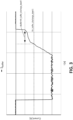
Figure 3 is a graphic showing a first option of discharge deactivation of the energy buffer module according to the present invention. -
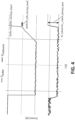
Figure 4 is a graphic showing a second option of discharge deactivation of the energy buffer module according to the present invention. -
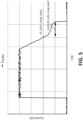
Figure 5 is a graphic showing a first option of charge deactivation of the energy buffer module according to the present invention. -
Figure 6 is a graphic showing a second option of charge deactivation of the energy buffer module according to the present invention. -
Figure 7 is a graphic showing an example of the parameters used for the calculation of the fixed voltage set-point. - The autonomous energy system for an aircraft according to the present invention, indicated generally with
reference number 8, comprises anenergy buffer module 1 used to support amain power source 2, which is, in this embodiment, a fuel cell, and ahigh voltage network 6 able to provide and receive power from theenergy buffer module 1. - The
energy buffer module 1 mainly supports the fuel cell to soften the fast power oscillations, preventing premature aging of the fuel cell. - In addition, the
energy buffer module 1 of the invention helps to reduce the time to reach the peak power demands when the fuel cell by itself is slower than the requested reaction times. - The
energy buffer module 1 comprises anenergy storage 3, in this embodiment a bank of supercapacitors, to provide thehigh voltage network 6 with the required power, and a voltage-controlled bidirectional DC-DC converter 4, to adapt the supercapacitors output voltage to the voltage of thehigh voltage network 6. Additionally, theenergy buffer module 1 comprises a powercontrol management system 5 which, being connected to theenergy storage 3 and to the DC-DC converter 4 is able to control the delivered power. - Due to the high power and low energy of the power profiles used to design the
energy buffer module 1, the supercapacitor technology was selected in this embodiment instead of the Li-ion battery cells due to its higher power density. On the other hand, the supercapacitors have the advantage that are more stable in high temperature conditions than the Li-ion cells, not affected by full discharge scenarios and less reactive under failures. - As mentioned, the power
control management system 5 of theenergy buffer module 1 is connected to theenergy storage 3, thehigh voltage network 6, and the voltage-controlled bidirectional DC-DC converter 4, for receiving and/or sending information and/or commands. So that, when the powercontrol management system 5 detects ahigh voltage network 6 instability, is capable of supporting themain power source 2 by itself with electrical power. To this end, as shown inFigure 2 , when the power control management system (5) detects that the voltage drop variation (ΔVd_network) of the high voltage network (6) is higher than a preset voltage discharge activation threshold (Vth_d_network_discharge_act) during a time (Δtd_network) higher than a preset time discharge activation value (tth_d_network_discharge_act), the power control management system (5) provides power from the energy buffer module (1) to the high voltage network (6) until one of a set of discharge deactivation conditions are met; and wherein the power control management system (5) is configured so that when the power control management system (5) detects that the voltage rise variation (ΔVr_network) of the high voltage network (6) is higher than a preset voltage charge activation threshold (Vth_r_network_charge_act) during a time (Δtnetwork) higher than a preset time charge activation value (tth_r_network_charge_act), the power control management system (5) receives power from the high voltage network (6) to the energy buffer module (1) until one of a set of charge deactivation conditions are met. - The discharge deactivation conditions can be one of the followings:
- the current provided by the energy buffer module (Ibuffer) (1) is lower than a first preset threshold discharge deactivation value (Ith_buffer_discharge_deact1) during a time (Δtbuffer) higher than a first preset discharge deactivation time (tth_buffer_discharge_deact1) -shown in
Figure 3 -, and - the charge of the energy storage (3) is lower than a minimum usable charge, and
- the voltage rise variation of the high voltage network (ΔVr_network) (6) is higher than a preset voltage rise discharge deactivation threshold (Vth_r_network_ discharge_deact) and the current provided by the energy buffer module (Ibuffer) (1) is lower than a second preset threshold discharge deactivation value (Ith_buffer_discharge_deact2) during a time (Δtbuffer) higher than a second preset discharge deactivation time (tth_buffer_ discharge deact2) -shown in
Figure 4 -. - The charge deactivation conditions can be one of the followings:
- the current provided by the energy buffer module (Ibuffer) (1) is lower than a first preset threshold charge deactivation value (Ith_buffer_charge_deact1) during a time (Δtbuffer) higher than a first preset charge deactivation time (tth_buffer_charge_deact1) -shown in
Figure 5 -, and - the charge of the energy storage (3) is higher than a maximum usable charge, and
- the voltage drop variation of the high voltage network (ΔVd_network) (6) is higher than a preset voltage drop charge deactivation threshold (Vth_d_network_charge_deact) and the current provided by the energy buffer module (Ibuffer) (1) is lower than a second preset threshold charge deactivation value (Ith_buffer_charge_deact2) during a time (Δtbuffer) higher than a second preset charge deactivation time (tth_buffer_charge_deact2) -shown in
Figure 6 -. - Preferably, the fixed voltage setpoint (Vset-point) provided by the energy buffer module (1) is determined from the average of the voltage values of the high voltage network (6) during a preset set-point time range (tset-point) established before a preset set-point back-time range (tset point_backpoint), said preset set-point back-time range (tset point_backpoint) comprising the time passed between the end of the preset set-point time range (tset point) and the current time (tcurrent).
Figure 7 shows an example of the fixed voltage setpoint (Vset-point) and the preset set-point time range (tset-point).
Claims (7)
- Autonomous energy system (8) for an aircraft comprising:- a high voltage network (6) capable to provide energy to aircraft electrical loads,- a main power source (2) connected to the high voltage network (6),- an energy storage (3),- a voltage-controlled bidirectional DC-DC converter (4) connected to the energy storage (3) and to the high voltage network (6),- and, a power control management system (5),
wherein- the power control management system (5) is connected to the high voltage network (6) to be able to measure its voltage variations,- wherein the power control management system (5) is connected to the energy storage (3) and to the DC-DC converter (4) to form an energy buffer module (1) capable of providing and receiving a determined amount of power by a fixed voltage setpoint (Vset-point) to the high voltage network (6),- wherein the power control management system (5) is configured so that when the power control management system (5) detects that the voltage drop variation (ΔVd_network) of the high voltage network (6) is higher than a preset voltage discharge activation threshold (Vth_d_network_discharge_act) during a time (Δtd_network) higher than a preset time discharge activation value (tth_d_network_discharge_act), the power control management system (5) provides power from the energy buffer module (1) to the high voltage network (6) until one of the following conditions are met:• the current provided by the energy buffer module (Ibuffer) (1) is lower than a first preset threshold discharge deactivation value (Ith_buffer_discharge_deact1) during a time (Δtbuffer) higher than a first preset discharge deactivation time (tth_buffer_discharge_deact1), and• the charge of the energy storage (3) is lower than a minimum usable charge, and• the voltage rise variation of the high voltage network (ΔVr_network) (6) is higher than a preset voltage rise discharge deactivation threshold (Vth_r_network_ discharge_deact) and the current provided by the energy buffer module (Ibuffer) (1) is lower than a second preset threshold discharge deactivation value (Ith_buffer_ discharge_deact2) during a time (Δtbuffer) higher than a second preset discharge deactivation time (tth_buffer_ discharge deact2),- and wherein the power control management system (5) is configured so that when the power control management system (5) detects that the voltage rise variation (ΔVr_network) of the high voltage network (6) is higher than a preset voltage charge activation threshold (Vth_r_network_charge_act) during a time (Δtnetwork) higher than a preset time charge activation value (tth_r_network_charge_act), the power control management system (5) receives power from the high voltage network (6) to the energy buffer module (1) until one of the following conditions are met:• the current provided by the energy buffer module (Ibuffer) (1) is lower than a first preset threshold charge deactivation value (Ith_buffer_charge_deact1) during a time (Δtbuffer) higher than a first preset charge deactivation time (tth_buffer_charge_deact1), and• the charge of the energy storage (3) is higher than a maximum usable charge, and• the voltage drop variation of the high voltage network (ΔVd_network) (6) is higher than a preset voltage drop charge deactivation threshold (Vth_d_network_charge_deact) and the current provided by the energy buffer module (Ibuffer) (1) is lower than a second preset threshold charge deactivation value (Ith_buffer_charge_deact2) during a time (Δtbuffer) higher than a second preset charge deactivation time (tth_buffer_charge_deact2). - Autonomous energy system (8) for an aircraft, according to claim 1, wherein the fixed voltage setpoint (Vset-point) provided by the energy buffer module (1) is determined from the voltage values of the high voltage network (6) during a preset set-point time range (tset-point).
- Autonomous energy system (8) for an aircraft, according to claim 2, wherein the fixed voltage setpoint (Vset-point) (1) is determined as the average of the voltage values of the high voltage network (6) during the preset set-point time range (tset-point).
- Autonomous energy system (8) for an aircraft, according to claim 3, wherein the preset set-point time range (tset point) is established before a preset set-point back-time range (tset point_backpoint), said preset set-point back-time range (tset point_backpoint) comprising the time passed between the end of the preset set-point time range (tset point) and the current time (tcurrent).
- Autonomous energy system (8) for an aircraft, according to any preceding claim, wherein the energy storage (3) and the DC-DC converter (4) are connected in series.
- Autonomous energy system (8) for an aircraft, according to any preceding claim, wherein the storage (3) is a bank of supercapacitors or lithium-ion (Li-on) batteries.
- Autonomous energy system (8) for an aircraft, according to any preceding claim, wherein the minimum usable charge of the energy storage (3) is lower than 20% of its entire charge, and the maximum usable charge of the energy storage (3) is higher than 80% of its entire charge.
Priority Applications (3)
| Application Number | Priority Date | Filing Date | Title |
|---|---|---|---|
| EP23382509.0A EP4472024A1 (en) | 2023-05-30 | 2023-05-30 | Autonomous energy system for an aircraft |
| CN202410670038.3A CN119070458A (en) | 2023-05-30 | 2024-05-28 | Autonomous energy systems for aircraft |
| US18/676,101 US12431705B2 (en) | 2023-05-30 | 2024-05-28 | Autonomous energy system for an aircraft |
Applications Claiming Priority (1)
| Application Number | Priority Date | Filing Date | Title |
|---|---|---|---|
| EP23382509.0A EP4472024A1 (en) | 2023-05-30 | 2023-05-30 | Autonomous energy system for an aircraft |
Publications (1)
| Publication Number | Publication Date |
|---|---|
| EP4472024A1 true EP4472024A1 (en) | 2024-12-04 |
Family
ID=86692831
Family Applications (1)
| Application Number | Title | Priority Date | Filing Date |
|---|---|---|---|
| EP23382509.0A Pending EP4472024A1 (en) | 2023-05-30 | 2023-05-30 | Autonomous energy system for an aircraft |
Country Status (3)
| Country | Link |
|---|---|
| US (1) | US12431705B2 (en) |
| EP (1) | EP4472024A1 (en) |
| CN (1) | CN119070458A (en) |
Citations (6)
| Publication number | Priority date | Publication date | Assignee | Title |
|---|---|---|---|---|
| US20140197681A1 (en) * | 2012-07-30 | 2014-07-17 | The Boeing Company | Electric system stabilizing system for aircraft |
| US20160105030A1 (en) * | 2014-10-08 | 2016-04-14 | Parker-Hannifin Corporation | Bus conditioner for an aircraft power system |
| US20170040795A1 (en) * | 2013-12-18 | 2017-02-09 | Daewoo Shipbuilding & Marine Engineering Co., Ltd. | Apparatus and method for supplying hybrid power of offshore plant |
| US20190004580A1 (en) * | 2017-06-30 | 2019-01-03 | Hamilton Sundstrand Corporation | Hesm parallel response mode |
| US20200136423A1 (en) * | 2018-10-29 | 2020-04-30 | Abb Schweiz Ag | Control of dc voltage distribution system |
| US20220258876A1 (en) * | 2021-02-17 | 2022-08-18 | Rolls-Royce Singapore Pte. Ltd. | Control for a target common bus voltage |
-
2023
- 2023-05-30 EP EP23382509.0A patent/EP4472024A1/en active Pending
-
2024
- 2024-05-28 CN CN202410670038.3A patent/CN119070458A/en active Pending
- 2024-05-28 US US18/676,101 patent/US12431705B2/en active Active
Patent Citations (6)
| Publication number | Priority date | Publication date | Assignee | Title |
|---|---|---|---|---|
| US20140197681A1 (en) * | 2012-07-30 | 2014-07-17 | The Boeing Company | Electric system stabilizing system for aircraft |
| US20170040795A1 (en) * | 2013-12-18 | 2017-02-09 | Daewoo Shipbuilding & Marine Engineering Co., Ltd. | Apparatus and method for supplying hybrid power of offshore plant |
| US20160105030A1 (en) * | 2014-10-08 | 2016-04-14 | Parker-Hannifin Corporation | Bus conditioner for an aircraft power system |
| US20190004580A1 (en) * | 2017-06-30 | 2019-01-03 | Hamilton Sundstrand Corporation | Hesm parallel response mode |
| US20200136423A1 (en) * | 2018-10-29 | 2020-04-30 | Abb Schweiz Ag | Control of dc voltage distribution system |
| US20220258876A1 (en) * | 2021-02-17 | 2022-08-18 | Rolls-Royce Singapore Pte. Ltd. | Control for a target common bus voltage |
Also Published As
| Publication number | Publication date |
|---|---|
| CN119070458A (en) | 2024-12-03 |
| US20240405541A1 (en) | 2024-12-05 |
| US12431705B2 (en) | 2025-09-30 |
Similar Documents
| Publication | Publication Date | Title |
|---|---|---|
| US10464441B2 (en) | Charging facility and energy management method for charging facility | |
| US7402982B2 (en) | Energy storage type feeder voltage compensation apparatus and method of controlling feeder voltage | |
| EP3620324B1 (en) | Power supply device, flying tool using same and power supply method thereof | |
| US10115990B2 (en) | Fuel cell system, fuel cell vehicle, and method for controlling fuel cell system | |
| JP5100132B2 (en) | Frequency adjustment system and frequency adjustment method | |
| JP5717172B2 (en) | Power supply system | |
| US9365175B2 (en) | Power supply system for vehicle | |
| EP3082210B1 (en) | Power generation system and method with energy management | |
| US20190004580A1 (en) | Hesm parallel response mode | |
| US9537310B2 (en) | Method of controlling the operation of a hybrid system | |
| CN112421746A (en) | Charging and discharging control and management method and device for SC-Li-SC mixed energy storage | |
| US20220344968A1 (en) | Electric drive system | |
| US20080085430A1 (en) | Battery integration and control in an auxiliary power unit powered by a solid oxide fuel cell system | |
| KR101888410B1 (en) | Management system for micro-grid | |
| US8889276B2 (en) | Method for managing the operation of a hybrid system | |
| KR102334713B1 (en) | Energy storage system and operation method thereof | |
| CN119070458A (en) | Autonomous energy systems for aircraft | |
| EP4418484A1 (en) | Energy storage management system | |
| US12337721B2 (en) | Bidirectional converter for a battery management system | |
| KR20250080345A (en) | Method and apparatus for maintaining high SOC of battery in ship |
Legal Events
| Date | Code | Title | Description |
|---|---|---|---|
| PUAI | Public reference made under article 153(3) epc to a published international application that has entered the european phase |
Free format text: ORIGINAL CODE: 0009012 |
|
| STAA | Information on the status of an ep patent application or granted ep patent |
Free format text: STATUS: THE APPLICATION HAS BEEN PUBLISHED |
|
| AK | Designated contracting states |
Kind code of ref document: A1 Designated state(s): AL AT BE BG CH CY CZ DE DK EE ES FI FR GB GR HR HU IE IS IT LI LT LU LV MC ME MK MT NL NO PL PT RO RS SE SI SK SM TR |
|
| STAA | Information on the status of an ep patent application or granted ep patent |
Free format text: STATUS: REQUEST FOR EXAMINATION WAS MADE |
|
| 17P | Request for examination filed |
Effective date: 20250820 |