EP4472014A1 - Secondary battery charging/discharging device - Google Patents
Secondary battery charging/discharging device Download PDFInfo
- Publication number
- EP4472014A1 EP4472014A1 EP23747347.5A EP23747347A EP4472014A1 EP 4472014 A1 EP4472014 A1 EP 4472014A1 EP 23747347 A EP23747347 A EP 23747347A EP 4472014 A1 EP4472014 A1 EP 4472014A1
- Authority
- EP
- European Patent Office
- Prior art keywords
- pin
- secondary battery
- positive electrode
- charging
- negative electrode
- Prior art date
- Legal status (The legal status is an assumption and is not a legal conclusion. Google has not performed a legal analysis and makes no representation as to the accuracy of the status listed.)
- Pending
Links
Images




Classifications
-
- H—ELECTRICITY
- H01—ELECTRIC ELEMENTS
- H01M—PROCESSES OR MEANS, e.g. BATTERIES, FOR THE DIRECT CONVERSION OF CHEMICAL ENERGY INTO ELECTRICAL ENERGY
- H01M10/00—Secondary cells; Manufacture thereof
- H01M10/42—Methods or arrangements for servicing or maintenance of secondary cells or secondary half-cells
- H01M10/46—Accumulators structurally combined with charging apparatus
-
- H—ELECTRICITY
- H01—ELECTRIC ELEMENTS
- H01M—PROCESSES OR MEANS, e.g. BATTERIES, FOR THE DIRECT CONVERSION OF CHEMICAL ENERGY INTO ELECTRICAL ENERGY
- H01M10/00—Secondary cells; Manufacture thereof
- H01M10/42—Methods or arrangements for servicing or maintenance of secondary cells or secondary half-cells
- H01M10/4285—Testing apparatus
-
- H—ELECTRICITY
- H01—ELECTRIC ELEMENTS
- H01M—PROCESSES OR MEANS, e.g. BATTERIES, FOR THE DIRECT CONVERSION OF CHEMICAL ENERGY INTO ELECTRICAL ENERGY
- H01M10/00—Secondary cells; Manufacture thereof
- H01M10/42—Methods or arrangements for servicing or maintenance of secondary cells or secondary half-cells
- H01M10/44—Methods for charging or discharging
-
- H—ELECTRICITY
- H01—ELECTRIC ELEMENTS
- H01M—PROCESSES OR MEANS, e.g. BATTERIES, FOR THE DIRECT CONVERSION OF CHEMICAL ENERGY INTO ELECTRICAL ENERGY
- H01M10/00—Secondary cells; Manufacture thereof
- H01M10/42—Methods or arrangements for servicing or maintenance of secondary cells or secondary half-cells
- H01M10/48—Accumulators combined with arrangements for measuring, testing or indicating the condition of cells, e.g. the level or density of the electrolyte
-
- H—ELECTRICITY
- H01—ELECTRIC ELEMENTS
- H01M—PROCESSES OR MEANS, e.g. BATTERIES, FOR THE DIRECT CONVERSION OF CHEMICAL ENERGY INTO ELECTRICAL ENERGY
- H01M10/00—Secondary cells; Manufacture thereof
- H01M10/42—Methods or arrangements for servicing or maintenance of secondary cells or secondary half-cells
- H01M10/48—Accumulators combined with arrangements for measuring, testing or indicating the condition of cells, e.g. the level or density of the electrolyte
- H01M10/486—Accumulators combined with arrangements for measuring, testing or indicating the condition of cells, e.g. the level or density of the electrolyte for measuring temperature
-
- H—ELECTRICITY
- H01—ELECTRIC ELEMENTS
- H01M—PROCESSES OR MEANS, e.g. BATTERIES, FOR THE DIRECT CONVERSION OF CHEMICAL ENERGY INTO ELECTRICAL ENERGY
- H01M50/00—Constructional details or processes of manufacture of the non-active parts of electrochemical cells other than fuel cells, e.g. hybrid cells
- H01M50/10—Primary casings; Jackets or wrappings
- H01M50/102—Primary casings; Jackets or wrappings characterised by their shape or physical structure
- H01M50/107—Primary casings; Jackets or wrappings characterised by their shape or physical structure having curved cross-section, e.g. round or elliptic
-
- H—ELECTRICITY
- H01—ELECTRIC ELEMENTS
- H01M—PROCESSES OR MEANS, e.g. BATTERIES, FOR THE DIRECT CONVERSION OF CHEMICAL ENERGY INTO ELECTRICAL ENERGY
- H01M50/00—Constructional details or processes of manufacture of the non-active parts of electrochemical cells other than fuel cells, e.g. hybrid cells
- H01M50/10—Primary casings; Jackets or wrappings
- H01M50/147—Lids or covers
-
- H—ELECTRICITY
- H02—GENERATION; CONVERSION OR DISTRIBUTION OF ELECTRIC POWER
- H02J—ELECTRIC POWER NETWORKS; CIRCUIT ARRANGEMENTS OR SYSTEMS FOR SUPPLYING OR DISTRIBUTING ELECTRIC POWER; SYSTEMS FOR STORING ELECTRIC ENERGY
- H02J7/00—Circuit arrangements for charging or discharging batteries or for supplying loads from batteries
-
- H—ELECTRICITY
- H02—GENERATION; CONVERSION OR DISTRIBUTION OF ELECTRIC POWER
- H02J—ELECTRIC POWER NETWORKS; CIRCUIT ARRANGEMENTS OR SYSTEMS FOR SUPPLYING OR DISTRIBUTING ELECTRIC POWER; SYSTEMS FOR STORING ELECTRIC ENERGY
- H02J7/00—Circuit arrangements for charging or discharging batteries or for supplying loads from batteries
- H02J7/70—Circuit arrangements for charging or discharging batteries or for supplying loads from batteries characterised by the mechanical construction
-
- Y—GENERAL TAGGING OF NEW TECHNOLOGICAL DEVELOPMENTS; GENERAL TAGGING OF CROSS-SECTIONAL TECHNOLOGIES SPANNING OVER SEVERAL SECTIONS OF THE IPC; TECHNICAL SUBJECTS COVERED BY FORMER USPC CROSS-REFERENCE ART COLLECTIONS [XRACs] AND DIGESTS
- Y02—TECHNOLOGIES OR APPLICATIONS FOR MITIGATION OR ADAPTATION AGAINST CLIMATE CHANGE
- Y02E—REDUCTION OF GREENHOUSE GAS [GHG] EMISSIONS, RELATED TO ENERGY GENERATION, TRANSMISSION OR DISTRIBUTION
- Y02E60/00—Enabling technologies; Technologies with a potential or indirect contribution to GHG emissions mitigation
- Y02E60/10—Energy storage using batteries
Definitions
- the present invention relates to a secondary battery charging/discharging apparatus.
- Secondary batteries may be recharged unlike primary batteries and have been extensively researched and developed in recent years due to small sizes and high capacities thereof. As technology development and demands for mobile devices increase, the demands for secondary batteries as energy sources are rapidly increasing.
- Secondary batteries are classified into coin-type batteries, cylindrical batteries, prismatic batteries, and pouch-type batteries, depending on the shapes of battery cases.
- an electrode assembly installed inside a battery case serves as a chargeable and dischargeable power generating element that has a structure in which electrodes and separators are stacked.
- the electrode assemblies may be generally classified into: a jelly-roll-type battery in which a separator is placed between a positive electrode and a negative electrode, each of which has the form of a sheet coated with an active material, and then wound; a stacking-type battery in which stacks, each of which has at least one electrode and at least one separator stacked on each other, are sequentially stacked; and a stacking/folding-type battery in which unit cells are wound together with a long separating film.
- a device inspects this actual battery by charging and discharging the same and is referred to as a charging/discharging device.
- the system performs a charging/discharging test by arranging charging/discharging pins above and below a battery and bringing these upper and lower pins into contact with the battery to conduct electricity.
- an insulator is disposed below a battery, making charging/discharging test through upper and lower pins impossible.
- One aspect of the present invention is to provide a secondary battery charging/discharging apparatus capable of charging and discharging secondary batteries of various specifications.
- a secondary battery charging/discharging apparatus is for charging and discharging a cylindrical secondary battery and performing a charging and discharging test by applying an electric current to the cylindrical secondary battery, wherein the cylindrical secondary battery includes an electrode assembly, in which a positive electrode, a separator, and a negative electrode are alternately wound, a can configured to accommodate the electrode assembly therein, and a positive electrode terminal positioned on one side of the can.
- the secondary battery charging/discharging apparatus includes a charging/discharging connection unit configured to come into contact with the positive electrode terminal electrically connected to the positive electrode and the can electrically connected to the negative electrode, wherein the charging/discharging connection unit is positioned in a region on one side of the secondary battery and brought into contact with and electrically connected to the positive electrode terminal and the can which are positioned on the one side of the secondary battery.
- a charging/discharging connection unit is provided to be electrically connected to a secondary battery on one side of the secondary battery, and thus, it is possible to perform a charging/discharging test for secondary batteries of various specifications.
- a positive electrode pin and a negative electrode pin of the charging/discharging connection unit are connected to the secondary battery on an upper side of the secondary battery, and thus, a secondary battery having an insulator positioned on a lower side thereof may also be charged and discharged.
- the charging/discharging connection unit includes a temperature pin that comes into contact with a can of the secondary battery to measure the temperature, and thus, the temperature of the secondary battery may be easily checked during charging and discharging of the secondary battery.
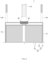
- FIG. 1 is a front view showing a secondary battery charging/discharging apparatus according to an embodiment of the present invention
- FIG. 2 is a cross-sectional view showing an example of a secondary battery applied in a secondary battery charging/discharging apparatus according to an embodiment of the present invention
- FIG. 3 is a cross-sectional view showing another example of a secondary battery applied in a secondary battery charging/discharging apparatus according to an embodiment of the present invention
- FIG. 4 is a perspective view showing a charging/discharging connection unit in a secondary battery charging/discharging apparatus according to a first embodiment of the present invention.
- a secondary battery charging/discharging apparatus 100 is for charging and discharging cylindrical secondary batteries 1 and 1' and performing a charging and discharging test by applying an electric current to the cylindrical secondary batteries that include electrode assemblies 20, cans 10 for accommodating the electrode assemblies 20 therein, and positive electrode terminals 30 and 30' positioned on one side of the cans 10.
- This secondary battery charging/discharging apparatus includes a charging/discharging connection unit S that comes into contact with the positive electrode terminals 30 and 30' electrically connected to positive electrodes 21 and the cans 10 electrically connected to negative electrodes 22.
- the secondary battery charging/discharging apparatus 100 may further include an upper die 170, a lower die 180, and a guide unit 190.
- each of the electrode assemblies 20 in the secondary batteries 1 and 1' applied in the secondary battery charging/discharging apparatus 100 serves as a power generating element capable of charging and discharging and may be configured by alternately stacking electrodes 23 and separators 24.
- the electrodes 23 include a positive electrode 21 and a negative electrode 22, and the electrode assembly 20 may have a cylindrical shape in which positive electrodes 21, separators 24, and negative electrodes 22 are alternately wound.
- each of the separators 24 separates and electrically insulate the positive electrode 21 and the negative electrode 22 from each other.
- the positive electrode 21 may include a positive electrode collector and a positive electrode active material stacked on the positive electrode collector.
- the positive electrode collector may include a foil made of an aluminum material.
- the positive electrode active material may include lithium manganese oxide, lithium cobalt oxide, lithium nickel oxide, lithium iron phosphate, or a compound or mixture including one or more thereof.
- the negative electrode 22 may include a negative electrode collector and a negative electrode active material stacked on the negative electrode collector.
- the negative electrode collector may include a foil made of, for example, a copper (Cu) material.
- the negative electrode active material may include a compound or mixture including a graphite-based material.
- the separator 24 includes an insulating material and electrically insulates the positive electrode 21 and the negative electrode 22 from each other.
- the separator 24 may include a polyolefin-based resin membrane, such as polyethylene and polypropylene, having microporous properties.
- the electrode assembly 20 may further include a positive electrode tab 25 provided at an end of the positive electrode 21 and a negative electrode tab provided at an end of the negative electrode 22.
- positive electrode tabs 25 may be electrically connected to the positive electrode terminals 30 and 30', respectively, and negative electrode tabs may be electrically connected to the cans 10, respectively.
- the can 10 has an accommodation portion open on one side and may accommodate the electrode assembly 20.
- the can 10 may be formed in a tubular shape in which the top is open and the bottom has a bottom surface.
- the can may be formed in, for example, a cylindrical shape to constitute cylindrical secondary batteries 1 and 1'.
- the can 10 may include a metal material.
- the positive electrode terminals 30 and 30' may be positioned on one side of the cans 10.
- the positive electrode terminals 30 and 30' may be positioned on the uppermost sides of the cans 10.
- the positive electrode terminals 30 and 30' may be positioned at the centers of the upper portions of the secondary batteries 1 and 1' in a plan view, and upper surfaces 11 of the cans 10 may be positioned on the outside of the upper portions of the secondary batteries 1 and 1'.
- gaskets 40 and 40' made of an insulating material may be provided between the positive electrode terminals 30 and 30' and the cans 10.
- a cap assembly may be formed which includes a positive electrode terminal 30 provided in the form of a top cap and a safety vent 50 and a safety element 60 provided below the positive electrode terminal 30.
- the positive electrode terminal 30 may be electrically connected to the positive electrode 21 through the safety vent 50 and the safety element 60 via the positive electrode tab 25.
- the upper portion of the can 10 surrounds the edge of the positive electrode terminal 30 having a top cap shape, and the positive electrode terminal 30 and the can 10 may be insulated from each other.
- gaskets 40 made of an insulating material may be provided between the positive electrode terminals 30 and 30' and the cans 10.
- a positive electrode tab connected to the positive electrode 21 may be directly connected to the positive electrode terminal 30'.
- the positive electrode terminal 30' may be provided in the form of, for example, a rivet.
- a gasket 40' insulating the positive electrode terminal 30' and the can 10 may be provided.
- the upper die 170 may be positioned above the secondary batteries 1 and 1', and the charging/discharging connection unit S may be installed thereto.
- the lower die 180 may be positioned below the secondary batteries 1 and 1'.
- the lower die 180 moves toward the upper die 170, and the positive electrode terminals 30 and 30' and the upper portions of the cans 10 of the secondary batteries 1 and 1' may be brought into contact with a positive electrode pin 110 and a negative electrode pin N, respectively.
- the lower die 180 may be moved in the up-down direction by a movement means.
- the movement means may include, for example, a pneumatic or hydraulic pressure actuator.
- the secondary batteries 1 and 1' may be seated on the lower die 180 while being accommodated in a tray T having an open top. Accordingly, the lower die 180 moves the tray, in which the secondary batteries 1 and 1' are accommodated, to the upper die 170, and thus, the upper portions of the secondary batteries 1 and 1' may be connected to the charging/discharging connection unit S.
- a guide unit 190 is connected to the upper die 170 and the lower die 180 and may guide the movement of the lower die 180.
- the guide unit 190 may be formed in a circular rod shape.
- FIG. 5 is a front view showing the charging/discharging connection unit in the secondary battery charging/discharging apparatus according to the first embodiment of the present invention
- FIG. 6 is a plan view showing the charging/discharging connection unit in the secondary battery charging/discharging apparatus according to the first embodiment of the present invention.
- the charging/discharging connection unit S may be positioned in regions on one side of the secondary batteries 1 and 1' and brought into contact with and electrically connected to the positive electrode terminals 30 and 30' and the cans 10 which are positioned on the one side of the secondary batteries 1 and 1'.
- the charging/discharging connection unit S may be positioned above the secondary batteries 1 and 1'.
- the charging/discharging connection unit S may include a positive electrode pin 110, which comes into contact with the positive electrode terminals 30 and 30', and a negative electrode pin N, which comes into contact with the cans 10.
- the charging/discharging connection unit S may further include a support block 150 and a temperature pin 140.
- An end of the positive electrode pin 110 may come into contact with upper surfaces 11 of the positive electrode terminals 30 and 30', and an end of the negative electrode pin N may come into contact with upper portions of the cans 10.
- the positive electrode pin 110 may be positioned at the center in a plan view, and the negative electrode pin N may be positioned around the positive electrode pin 110 in a plan view and spaced a certain distance from the positive electrode pin 110.
- the negative electrode pin N may be provided in plurality, and the plurality of negative electrode pins may include a negative electrode current pin 120 and a negative electrode voltage pin 130.
- the number of each of the negative electrode current pin 120 and the negative electrode voltage pin 130 in the negative electrode pin N of the charging/discharging connection unit S may be one or more.
- the negative electrode pin N of the charging/discharging connection unit S may be provided with three negative electrode current pins 120 and two negative electrode voltage pins 130.
- the negative electrode pin N includes the negative electrode current pins 120 and the negative electrode voltage pins 130, and thus, the size thereof may be reduced compared to when the current pin and the voltage pin are integrated as a single body. That is, the negative electrode pin N is provided with a plurality of negative electrode current pins 120 and negative electrode voltage pins 130, and thus, resistance of electricity flowing through each negative electrode voltage pin N is reduced. Accordingly, the negative electrode pin N may be formed thinner. Accordingly, it is possible to prevent a short circuit caused by contact between the negative electrode pin N and the positive electrode terminals 30 and 30'.
- the temperature pin 140 may come into contact with the upper portion of the can 10 and measure the temperature of the contact surface.
- the temperature pin 140 may be positioned around the positive electrode pin 110 in a plan view and spaced a certain distance from the positive electrode pin 110.
- the support block 150 may support the positive electrode pin 110, the negative electrode pin N, and the temperature pin 140.
- the support block 150 may be installed to a lower portion of the upper die 170.
- the positive electrode pin 110, the negative electrode pin N, and the temperature pin 140 may protrude downward from the support block 150.
- a positive electrode pin-elastic part 111, a negative electrode pin-elastic part N1, and a temperature pin-elastic part 141 may be further provided in some portions of the positive electrode pin 110, the negative electrode pin N, and the temperature pin 140, respectively, which protrude downward from the support block 150. Accordingly, when the positive electrode pin 110, the negative electrode pin N, and the temperature pin 140 come into contact with the upper portions of the secondary batteries 1 and 1', impact may be absorbed by the positive electrode pin-elastic part 111, the negative electrode pin-elastic part N1, and the temperature pin-elastic part 141.
- the positive electrode pin-elastic part 111, the negative electrode pin-elastic part N1, and the temperature pin-elastic part 141 may be positioned between the support block 150 and ends of the positive electrode pin-elastic part 111, the negative electrode pin-elastic part N1, and the temperature pin-elastic part 141, respectively.
- the positive electrode pin-elastic part 111, the negative electrode pin-elastic part N1, and the temperature pin-elastic part 141 may be provided in the form of, for example, a coil spring.
- the negative electrode pin-elastic part N1 may include a negative electrode current pin-elastic part 121 provided in the negative electrode current pin 120 and a negative electrode voltage pin-elastic part 131 provided in the negative electrode voltage pin 130.
- the charging/discharging connection unit S is provided to be electrically connected to the secondary batteries 1 and 1' on upper sides of the secondary batteries 1 and 1'. Accordingly, it is possible to charge and discharge secondary batteries 1 and 1' of various specifications and perform charging/discharging tests therefor.
- the positive electrode pin 110 and the negative electrode pin N of the charging/discharging connection unit S are connected to the secondary batteries 1 and 1' on upper sides thereof, and thus, the secondary batteries 1 and 1' having an insulator positioned on lower sides thereof may also be charged and discharged.
- the charging/discharging connection unit S includes the temperature pin 15 that comes into contact with the cans 10 of the secondary batteries 1 and 1' to measure the temperature, and thus, the temperatures of the secondary batteries 1 and 1' may be easily checked during charging and discharging of the secondary batteries 1 and 1'.
- a secondary battery charging/discharging apparatus according to a second embodiment of the present invention is descried below.
- FIG. 7 is a perspective view showing a charging/discharging connection unit in the secondary battery charging/discharging apparatus according to the second embodiment of the present invention.
- the secondary battery charging/discharging apparatus is for charging and discharging cylindrical secondary batteries 1 and 1' and performing a charging and discharging test by applying an electric current to the cylindrical secondary batteries that include electrode assemblies 20, cans 10 for accommodating the electrode assemblies 20 therein, and positive electrode terminals 30 and 30' positioned on one side of the cans 10.
- This secondary battery charging/discharging apparatus includes a charging/discharging connection unit S' that comes into contact with the positive electrode terminals 30 and 30' electrically connected to positive electrodes 21 and the cans 10 electrically connected to negative electrodes 22.
- the secondary battery charging/discharging apparatus according to the second embodiment of the present invention may further include an upper die 170, a lower die 180, and a guide unit 190 (see FIG. 1 ) .
- the secondary battery charging/discharging apparatus according to the second embodiment of the present invention is different from the secondary battery charging/discharging apparatus according to the first embodiment described above in that configurations for adjusting the positions of a negative electrode pin N and a temperature pin 140 are further provided in the charging/discharging connection unit S'.
- this embodiment is described with a focus on differences from the above embodiment, and repeated descriptions are omitted or briefly described.
- FIG. 8 is a front view showing the charging/discharging connection unit in the secondary battery charging/discharging apparatus according to the second embodiment of the present invention
- FIG. 9 is a plan view showing the charging/discharging connection unit in the secondary battery charging/discharging apparatus according to the second embodiment of the present invention.
- the charging/discharging connection unit S' may be positioned in regions on one side of the secondary batteries 1 and 1' and brought into contact with and electrically connected to the positive electrode terminals 30 and 30' and the cans 10 which are positioned on the one side of the secondary batteries 1 and 1'.
- the charging/discharging connection unit S' may be positioned above the secondary batteries 1 and 1'.
- the charging/discharging connection unit S' may include a positive electrode pin 110, which comes into contact with the positive electrode terminals 30 and 30', and a negative electrode pin N, which comes into contact with the cans 10.
- the charging/discharging connection unit S' may further include a support block 250 and a temperature pin 140.
- An end of the positive electrode pin 110 may come into contact with upper surfaces 11 of the positive electrode terminals 30 and 30', and an end of the negative electrode pin N may come into contact with upper portions of the cans 10.
- the positive electrode pin 110 may be positioned at the center in a plan view, and the negative electrode pin N may be positioned around the positive electrode pin 110 in a plan view and spaced a certain distance from the positive electrode pin 110.
- the negative electrode pin N may be provided in plurality, and the plurality of negative electrode pins may include a negative electrode current pin 120 and a negative electrode voltage pin 130.
- the number of each of the negative electrode current pin 120 and the negative electrode voltage pin 130 in the negative electrode pin N of the charging/discharging connection unit S' may be one or more.
- the negative electrode pin N of the charging/discharging connection unit S' may be provided with three negative electrode current pins 120 and two negative electrode voltage pins 130.
- the temperature pin 140 may come into contact with the upper portion of the can 10 and measure the temperature of the contact surface.
- the temperature pin 140 may be positioned around the positive electrode pin 110 in a plan view and spaced a certain distance from the positive electrode pin 110.
- the support block 250 may support the positive electrode pin 110, the negative electrode pin N, and the temperature pin 140.
- the support block 250 may further include a position adjustment hole 251 which extends in a width direction W of the support block 250.
- the negative electrode pin N and the temperature pin 140 may pass through the position adjustment hole 251, be installed to the support block 250, and move along the position adjustment hole 251 in the width direction W of the support block 250 to thereby adjust positions thereof. Accordingly, it is possible to adjust the distance between the positive electrode pin 110 and each of the negative electrode pin N and the temperature pin 140, and thus, secondary batteries having various widths may be easily charged and discharged.
- the charging/discharging connection unit S' may further include a fixing means 260 that fixes the positions of the negative electrode pin N and the temperature pin 140 to the support block.
- the fixing means 260 may include, for example, a plurality of nuts 261 and 262.
- the plurality of nuts 261 and 262 may be coupled to each of the negative electrode pin N and the temperature pin 140.
- the negative electrode pin N and the temperature pin 140 have threads formed along the outer circumferential surfaces thereof and may be screw-coupled to the plurality of nuts 261 and 262 having thread grooves formed on the inner circumferential surfaces.
- the plurality of nuts 261 and 262 may include a first nut 261 positioned on an upper surface of the support block 250 and a second nut 262 positioned on a lower surface of the support block 250. That is, the first nut 261 and the second nut 262 are coupled to each of the negative electrode pin N and the temperature pin 140, and thus, the positions of the negative electrode pin N and the temperature pin 140 may be fixed to the support block 250.
- a positive electrode pin-elastic part 111, a negative electrode pin-elastic part N1, and a temperature pin-elastic part 141 may be further provided in some portions of the positive electrode pin 110, the negative electrode pin N, and the temperature pin 140, respectively, which protrude downward from the support block 250. Accordingly, when the positive electrode pin 110, the negative electrode pin N, and the temperature pin 140 come into contact with the upper portions of the secondary batteries 1 and 1', impact may be absorbed by the positive electrode pin-elastic part 111, the negative electrode pin-elastic part N1, and the temperature pin-elastic part 141.
- the positive electrode pin-elastic part 111, the negative electrode pin-elastic part N1, and the temperature pin-elastic part 141 may be positioned between the support block 250 and ends of the positive electrode pin-elastic part 111, the negative electrode pin-elastic part N1, and the temperature pin-elastic part 141, respectively.
- the positive electrode pin-elastic part 111, the negative electrode pin-elastic part N1, and the temperature pin-elastic part 141 may be provided in the form of, for example, a coil spring.
- the negative electrode pin-elastic part N1 may include a negative electrode current pin-elastic part 121 provided in the negative electrode current pin 120 and a negative electrode voltage pin-elastic part 131 provided in the negative electrode voltage pin 130.
- a secondary battery charging/discharging apparatus according to a third embodiment of the present invention is descried below.
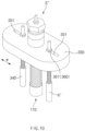
- FIG. 10 is a perspective view showing a charging/discharging connection unit in a secondary battery charging/discharging apparatus according to a third embodiment of the present invention.
- the secondary battery charging/discharging apparatus is for charging and discharging cylindrical secondary batteries 1 and 1' and performing a charging and discharging test by applying an electric current to the cylindrical secondary batteries that include electrode assemblies 20, cans 10 for accommodating the electrode assemblies 20 therein, and positive electrode terminals 30 and 30' positioned on one side of the cans 10.
- This secondary battery charging/discharging apparatus includes a charging/discharging connection unit S" that comes into contact with the positive electrode terminals 30 and 30' electrically connected to positive electrodes 21 and the cans 10 electrically connected to negative electrodes 22.
- the secondary battery charging/discharging apparatus according to the third embodiment of the present invention may further include an upper die, a lower die, and a guide unit.
- the secondary battery charging/discharging apparatus according to the third embodiment of the present invention is different from the secondary battery charging/discharging apparatuses according to the first embodiment and the second embodiment described above in that the number of a negative electrode pin N" and a temperature pin 340 provided in the charging/discharging connection unit S" is one.
- this embodiment is described with a focus on differences from the above embodiments, and repeated descriptions are omitted or briefly described.
- the charging/discharging connection unit S" may be positioned in regions on one side of the secondary batteries 1 and 1' and brought into contact with and electrically connected to the positive electrode terminals 30 and 30' and the cans 10 which are positioned on the one side of the secondary batteries 1 and 1'.
- the charging/discharging connection unit S" may be positioned above the secondary batteries 1 and 1'.
- the charging/discharging connection unit S" may include a positive electrode pin 110, which comes into contact with the positive electrode terminals 30 and 30', and a negative electrode pin N", which comes into contact with the cans 10.
- the charging/discharging connection unit S" may further include a support block 350 and a temperature pin 140.
- An end of the positive electrode pin 110 may come into contact with upper surfaces 11 of the positive electrode terminals 30 and 30', and an end of the negative electrode pin N" may come into contact with upper portions of the cans 10.
- the positive electrode pin 110 may be positioned at the center in a plan view, and the negative electrode pin N" may be spaced a certain distance from the positive electrode pin 110 in a plan view.
- the number of negative electrode pin N" is one, and current and voltage may flow therethrough.
- One negative electrode pin N" is provided, and occupies less space than when provided in plurality, and thus, space utilization may be improved.
- the temperature pin 140 may come into contact with the upper portion of the can 10 and measure the temperature of the contact surface.
- the temperature pin 140 may be spaced a certain distance from the positive electrode pin 110 in a plan view.
- the support block 350 may support the positive electrode pin 110, the negative electrode pin N", and the temperature pin 140.
- the support block 350 may further include a position adjustment hole 351 which extends in a width direction W of the support block 350.
- the negative electrode pin N" and the temperature pin 340 may pass through the position adjustment hole 351, be installed to the support block 350, and move along the position adjustment hole 351 in the width direction W of the support block 350 to thereby adjust positions thereof. Accordingly, it is possible to adjust the distance between the positive electrode pin 110 and each of the negative electrode pin N" and the temperature pin 340, and thus, secondary batteries having various widths may be easily charged and discharged.
- the charging/discharging connection unit S" may further include a fixing means 360 that fixes the positions of the negative electrode pin N" and the temperature pin 340 to the support block.
- the fixing means 360 may include, for example, a plurality of nuts 361.
- the plurality of nuts 361 may be coupled to each of the negative electrode pin N" and the temperature pin 340.
- the negative electrode pin and the temperature pin have threads formed along the outer circumferential surfaces thereof and may be screw-coupled to the plurality of nuts 361 having thread grooves formed on the inner circumferential surfaces.
- a positive electrode pin-elastic part, a negative electrode pin-elastic part, a temperature pin-elastic part may be further provided in some portions of the positive electrode pin 110, the negative electrode pin N", and the temperature pin 140, respectively, which protrude downward from the support block 350.
Landscapes
- Chemical & Material Sciences (AREA)
- Chemical Kinetics & Catalysis (AREA)
- Electrochemistry (AREA)
- General Chemical & Material Sciences (AREA)
- Engineering & Computer Science (AREA)
- Manufacturing & Machinery (AREA)
- Power Engineering (AREA)
- Secondary Cells (AREA)
- Charge And Discharge Circuits For Batteries Or The Like (AREA)
Abstract
Description
- The present application claims the benefit of the priority of
Korean Patent Application Nos. 10-2022-0011603, filed on January 26, 2022 10-2023-0010022, filed on January 26, 2023 - The present invention relates to a secondary battery charging/discharging apparatus.
- Secondary batteries may be recharged unlike primary batteries and have been extensively researched and developed in recent years due to small sizes and high capacities thereof. As technology development and demands for mobile devices increase, the demands for secondary batteries as energy sources are rapidly increasing.
- Secondary batteries are classified into coin-type batteries, cylindrical batteries, prismatic batteries, and pouch-type batteries, depending on the shapes of battery cases. In such a secondary battery, an electrode assembly installed inside a battery case serves as a chargeable and dischargeable power generating element that has a structure in which electrodes and separators are stacked.
- The electrode assemblies may be generally classified into: a jelly-roll-type battery in which a separator is placed between a positive electrode and a negative electrode, each of which has the form of a sheet coated with an active material, and then wound; a stacking-type battery in which stacks, each of which has at least one electrode and at least one separator stacked on each other, are sequentially stacked; and a stacking/folding-type battery in which unit cells are wound together with a long separating film.
- After a battery is assembled in a lithium ion battery manufacturing process, a device inspects this actual battery by charging and discharging the same and is referred to as a charging/discharging device.
- In a charging/discharging system according to the related art, the system performs a charging/discharging test by arranging charging/discharging pins above and below a battery and bringing these upper and lower pins into contact with the battery to conduct electricity.
- As various types of batteries have been developed recently, an insulator is disposed below a battery, making charging/discharging test through upper and lower pins impossible.
- Therefore, there is a demand for a new charging/discharging system other than the charging/discharging system using the upper and lower pins.
- One aspect of the present invention is to provide a secondary battery charging/discharging apparatus capable of charging and discharging secondary batteries of various specifications.
- A secondary battery charging/discharging apparatus according to an embodiment of the present invention is for charging and discharging a cylindrical secondary battery and performing a charging and discharging test by applying an electric current to the cylindrical secondary battery, wherein the cylindrical secondary battery includes an electrode assembly, in which a positive electrode, a separator, and a negative electrode are alternately wound, a can configured to accommodate the electrode assembly therein, and a positive electrode terminal positioned on one side of the can. The secondary battery charging/discharging apparatus includes a charging/discharging connection unit configured to come into contact with the positive electrode terminal electrically connected to the positive electrode and the can electrically connected to the negative electrode, wherein the charging/discharging connection unit is positioned in a region on one side of the secondary battery and brought into contact with and electrically connected to the positive electrode terminal and the can which are positioned on the one side of the secondary battery.
- According to the present invention, a charging/discharging connection unit is provided to be electrically connected to a secondary battery on one side of the secondary battery, and thus, it is possible to perform a charging/discharging test for secondary batteries of various specifications. Here, a positive electrode pin and a negative electrode pin of the charging/discharging connection unit are connected to the secondary battery on an upper side of the secondary battery, and thus, a secondary battery having an insulator positioned on a lower side thereof may also be charged and discharged.
- In addition, the charging/discharging connection unit includes a temperature pin that comes into contact with a can of the secondary battery to measure the temperature, and thus, the temperature of the secondary battery may be easily checked during charging and discharging of the secondary battery.
-
-
FIG. 1 is a front view showing a secondary battery charging/discharging apparatus according to an embodiment of the present invention. -
FIG. 2 is a cross-sectional view showing an example of a secondary battery applied in a secondary battery charging/discharging apparatus according to an embodiment of the present invention. -
FIG. 3 is a cross-sectional view showing another example of a secondary battery applied in a secondary battery charging/discharging apparatus according to an embodiment of the present invention. -
FIG. 4 is a perspective view showing a charging/discharging connection unit in a secondary battery charging/discharging apparatus according to a first embodiment of the present invention. -
FIG. 5 is a front view showing the charging/discharging connection unit in the secondary battery charging/discharging apparatus according to the first embodiment of the present invention. -
FIG. 6 is a plan view showing the charging/discharging connection unit in the secondary battery charging/discharging apparatus according to the first embodiment of the present invention. -
FIG. 7 is a perspective view showing a charging/discharging connection unit in a secondary battery charging/discharging apparatus according to a second embodiment of the present invention. -
FIG. 8 is a front view showing the charging/discharging connection unit in the secondary battery charging/discharging apparatus according to the second embodiment of the present invention. -
FIG. 9 is a plan view showing the charging/discharging connection unit in the secondary battery charging/discharging apparatus according to the second embodiment of the present invention. -
FIG. 10 is a perspective view showing a charging/discharging connection unit in a secondary battery charging/discharging apparatus according to a third embodiment of the present invention. - The objects, specific advantages, and novel features of the present invention will be more clearly understood from the following detailed description and preferred embodiments taken in conjunction with the accompanying drawings. In the specification, when reference numerals are given to elements in each drawing, it should be noted that the same elements will be designated by the same reference numerals if possible although they are shown in different drawings. Also, the present invention may be embodied in various different forms, and is not limited to the embodiments described herein. In addition, in describing the present invention, detailed descriptions related to well-known functions are omitted so as not to unnecessarily obscure subject matters of the present invention.
-
FIG. 1 is a front view showing a secondary battery charging/discharging apparatus according to an embodiment of the present invention,FIG. 2 is a cross-sectional view showing an example of a secondary battery applied in a secondary battery charging/discharging apparatus according to an embodiment of the present invention,FIG. 3 is a cross-sectional view showing another example of a secondary battery applied in a secondary battery charging/discharging apparatus according to an embodiment of the present invention, andFIG. 4 is a perspective view showing a charging/discharging connection unit in a secondary battery charging/discharging apparatus according to a first embodiment of the present invention. - Referring to
FIGS. 1 to 3 , a secondary battery charging/dischargingapparatus 100 according to a first embodiment of the present invention is for charging and discharging cylindricalsecondary batteries 1 and 1' and performing a charging and discharging test by applying an electric current to the cylindrical secondary batteries that includeelectrode assemblies 20,cans 10 for accommodating theelectrode assemblies 20 therein, andpositive electrode terminals 30 and 30' positioned on one side of thecans 10. This secondary battery charging/discharging apparatus includes a charging/discharging connection unit S that comes into contact with thepositive electrode terminals 30 and 30' electrically connected topositive electrodes 21 and thecans 10 electrically connected tonegative electrodes 22. - Also, the secondary battery charging/
discharging apparatus 100 according to the first embodiment of the present invention may further include anupper die 170, alower die 180, and aguide unit 190. - More specifically, each of the electrode assemblies 20 in the
secondary batteries 1 and 1' applied in the secondary battery charging/dischargingapparatus 100 according to the first embodiment of the present invention serves as a power generating element capable of charging and discharging and may be configured by alternately stackingelectrodes 23 andseparators 24. Here, theelectrodes 23 include apositive electrode 21 and anegative electrode 22, and theelectrode assembly 20 may have a cylindrical shape in whichpositive electrodes 21,separators 24, andnegative electrodes 22 are alternately wound. Here, each of theseparators 24 separates and electrically insulate thepositive electrode 21 and thenegative electrode 22 from each other. - The
positive electrode 21 may include a positive electrode collector and a positive electrode active material stacked on the positive electrode collector. - The positive electrode collector may include a foil made of an aluminum material.
- The positive electrode active material may include lithium manganese oxide, lithium cobalt oxide, lithium nickel oxide, lithium iron phosphate, or a compound or mixture including one or more thereof.
- The
negative electrode 22 may include a negative electrode collector and a negative electrode active material stacked on the negative electrode collector. - The negative electrode collector may include a foil made of, for example, a copper (Cu) material.
- The negative electrode active material may include a compound or mixture including a graphite-based material.
- The
separator 24 includes an insulating material and electrically insulates thepositive electrode 21 and thenegative electrode 22 from each other. Here, theseparator 24 may include a polyolefin-based resin membrane, such as polyethylene and polypropylene, having microporous properties. - Also, the
electrode assembly 20 may further include apositive electrode tab 25 provided at an end of thepositive electrode 21 and a negative electrode tab provided at an end of thenegative electrode 22. Here,positive electrode tabs 25 may be electrically connected to thepositive electrode terminals 30 and 30', respectively, and negative electrode tabs may be electrically connected to thecans 10, respectively. - The
can 10 has an accommodation portion open on one side and may accommodate theelectrode assembly 20. Here, thecan 10 may be formed in a tubular shape in which the top is open and the bottom has a bottom surface. Here, the can may be formed in, for example, a cylindrical shape to constitute cylindricalsecondary batteries 1 and 1'. Also, thecan 10 may include a metal material. - The
positive electrode terminals 30 and 30' may be positioned on one side of thecans 10. Here, for example, thepositive electrode terminals 30 and 30' may be positioned on the uppermost sides of thecans 10. - The
positive electrode terminals 30 and 30' may be positioned at the centers of the upper portions of thesecondary batteries 1 and 1' in a plan view, andupper surfaces 11 of thecans 10 may be positioned on the outside of the upper portions of thesecondary batteries 1 and 1'. Here,gaskets 40 and 40' made of an insulating material may be provided between thepositive electrode terminals 30 and 30' and thecans 10. - Also, in the
secondary battery 1, for example, a cap assembly may be formed which includes apositive electrode terminal 30 provided in the form of a top cap and asafety vent 50 and asafety element 60 provided below thepositive electrode terminal 30. Here, regarding thepositive electrode terminals 30 and 30', thepositive electrode terminal 30 may be electrically connected to thepositive electrode 21 through thesafety vent 50 and thesafety element 60 via thepositive electrode tab 25. Here, the upper portion of thecan 10 surrounds the edge of thepositive electrode terminal 30 having a top cap shape, and thepositive electrode terminal 30 and thecan 10 may be insulated from each other. Here,gaskets 40 made of an insulating material may be provided between thepositive electrode terminals 30 and 30' and thecans 10. - Also, in the secondary battery 1' as another example, a positive electrode tab connected to the
positive electrode 21 may be directly connected to the positive electrode terminal 30'. Here, the positive electrode terminal 30' may be provided in the form of, for example, a rivet. Here, a gasket 40' insulating the positive electrode terminal 30' and thecan 10 may be provided. - Referring to
FIG. 1 , theupper die 170 may be positioned above thesecondary batteries 1 and 1', and the charging/discharging connection unit S may be installed thereto. - The
lower die 180 may be positioned below thesecondary batteries 1 and 1'. - The
lower die 180 moves toward theupper die 170, and thepositive electrode terminals 30 and 30' and the upper portions of thecans 10 of thesecondary batteries 1 and 1' may be brought into contact with apositive electrode pin 110 and a negative electrode pin N, respectively. Here, thelower die 180 may be moved in the up-down direction by a movement means. The movement means may include, for example, a pneumatic or hydraulic pressure actuator. - Here, the
secondary batteries 1 and 1' may be seated on thelower die 180 while being accommodated in a tray T having an open top. Accordingly, thelower die 180 moves the tray, in which thesecondary batteries 1 and 1' are accommodated, to theupper die 170, and thus, the upper portions of thesecondary batteries 1 and 1' may be connected to the charging/discharging connection unit S. - A
guide unit 190 is connected to theupper die 170 and thelower die 180 and may guide the movement of thelower die 180. Theguide unit 190 may be formed in a circular rod shape. -
FIG. 5 is a front view showing the charging/discharging connection unit in the secondary battery charging/discharging apparatus according to the first embodiment of the present invention, andFIG. 6 is a plan view showing the charging/discharging connection unit in the secondary battery charging/discharging apparatus according to the first embodiment of the present invention. - Referring to
FIGS. 4 to 6 , the charging/discharging connection unit S may be positioned in regions on one side of thesecondary batteries 1 and 1' and brought into contact with and electrically connected to thepositive electrode terminals 30 and 30' and thecans 10 which are positioned on the one side of thesecondary batteries 1 and 1'. Here, the charging/discharging connection unit S may be positioned above thesecondary batteries 1 and 1'. - Also, the charging/discharging connection unit S may include a
positive electrode pin 110, which comes into contact with thepositive electrode terminals 30 and 30', and a negative electrode pin N, which comes into contact with thecans 10. In addition, the charging/discharging connection unit S may further include asupport block 150 and atemperature pin 140. - An end of the
positive electrode pin 110 may come into contact withupper surfaces 11 of thepositive electrode terminals 30 and 30', and an end of the negative electrode pin N may come into contact with upper portions of thecans 10. - The
positive electrode pin 110 may be positioned at the center in a plan view, and the negative electrode pin N may be positioned around thepositive electrode pin 110 in a plan view and spaced a certain distance from thepositive electrode pin 110. - The negative electrode pin N may be provided in plurality, and the plurality of negative electrode pins may include a negative electrode
current pin 120 and a negativeelectrode voltage pin 130. - Here, the number of each of the negative electrode
current pin 120 and the negativeelectrode voltage pin 130 in the negative electrode pin N of the charging/discharging connection unit S may be one or more. Here, for example, the negative electrode pin N of the charging/discharging connection unit S may be provided with three negative electrodecurrent pins 120 and two negative electrode voltage pins 130. - Therefore, the negative electrode pin N includes the negative electrode
current pins 120 and the negative electrode voltage pins 130, and thus, the size thereof may be reduced compared to when the current pin and the voltage pin are integrated as a single body. That is, the negative electrode pin N is provided with a plurality of negative electrodecurrent pins 120 and negative electrode voltage pins 130, and thus, resistance of electricity flowing through each negative electrode voltage pin N is reduced. Accordingly, the negative electrode pin N may be formed thinner. Accordingly, it is possible to prevent a short circuit caused by contact between the negative electrode pin N and thepositive electrode terminals 30 and 30'. - The
temperature pin 140 may come into contact with the upper portion of thecan 10 and measure the temperature of the contact surface. - The
temperature pin 140 may be positioned around thepositive electrode pin 110 in a plan view and spaced a certain distance from thepositive electrode pin 110. - The
support block 150 may support thepositive electrode pin 110, the negative electrode pin N, and thetemperature pin 140. - Also, the
support block 150 may be installed to a lower portion of theupper die 170. Here, thepositive electrode pin 110, the negative electrode pin N, and thetemperature pin 140 may protrude downward from thesupport block 150. - Meanwhile, a positive electrode pin-elastic part 111, a negative electrode pin-elastic part N1, and a temperature pin-
elastic part 141 may be further provided in some portions of thepositive electrode pin 110, the negative electrode pin N, and thetemperature pin 140, respectively, which protrude downward from thesupport block 150. Accordingly, when thepositive electrode pin 110, the negative electrode pin N, and thetemperature pin 140 come into contact with the upper portions of thesecondary batteries 1 and 1', impact may be absorbed by the positive electrode pin-elastic part 111, the negative electrode pin-elastic part N1, and the temperature pin-elastic part 141. Also, when deviations occur in the distances from the upper portions of thesecondary batteries 1 and 1' to thepositive electrode pin 110, the negative electrode pin N, and thetemperature pin 140, these deviations may be eliminated by the positive electrode pin-elastic part 111, the negative electrode pin-elastic part N1, and the temperature pin-elastic part 141. - The positive electrode pin-elastic part 111, the negative electrode pin-elastic part N1, and the temperature pin-
elastic part 141 may be positioned between thesupport block 150 and ends of the positive electrode pin-elastic part 111, the negative electrode pin-elastic part N1, and the temperature pin-elastic part 141, respectively. - The positive electrode pin-elastic part 111, the negative electrode pin-elastic part N1, and the temperature pin-
elastic part 141 may be provided in the form of, for example, a coil spring. - Meanwhile, the negative electrode pin-elastic part N1 may include a negative electrode current pin-
elastic part 121 provided in the negative electrodecurrent pin 120 and a negative electrode voltage pin-elastic part 131 provided in the negativeelectrode voltage pin 130. - Referring to
FIGS. 1 to 4 , in the secondary battery charging/dischargingapparatus 100 having the above configuration according to the first embodiment of the present invention, the charging/discharging connection unit S is provided to be electrically connected to thesecondary batteries 1 and 1' on upper sides of thesecondary batteries 1 and 1'. Accordingly, it is possible to charge and dischargesecondary batteries 1 and 1' of various specifications and perform charging/discharging tests therefor. Here, thepositive electrode pin 110 and the negative electrode pin N of the charging/discharging connection unit S are connected to thesecondary batteries 1 and 1' on upper sides thereof, and thus, thesecondary batteries 1 and 1' having an insulator positioned on lower sides thereof may also be charged and discharged. - In addition, the charging/discharging connection unit S includes the temperature pin 15 that comes into contact with the
cans 10 of thesecondary batteries 1 and 1' to measure the temperature, and thus, the temperatures of thesecondary batteries 1 and 1' may be easily checked during charging and discharging of thesecondary batteries 1 and 1'. - A secondary battery charging/discharging apparatus according to a second embodiment of the present invention is descried below.
-
FIG. 7 is a perspective view showing a charging/discharging connection unit in the secondary battery charging/discharging apparatus according to the second embodiment of the present invention. - Referring to
FIGS. 2 ,3 , and7 , the secondary battery charging/discharging apparatus according to the second embodiment of the present invention is for charging and discharging cylindricalsecondary batteries 1 and 1' and performing a charging and discharging test by applying an electric current to the cylindrical secondary batteries that includeelectrode assemblies 20,cans 10 for accommodating theelectrode assemblies 20 therein, andpositive electrode terminals 30 and 30' positioned on one side of thecans 10. This secondary battery charging/discharging apparatus includes a charging/discharging connection unit S' that comes into contact with thepositive electrode terminals 30 and 30' electrically connected topositive electrodes 21 and thecans 10 electrically connected tonegative electrodes 22. Also, like the first embodiment described above, the secondary battery charging/discharging apparatus according to the second embodiment of the present invention may further include anupper die 170, alower die 180, and a guide unit 190 (seeFIG. 1 ) . - The secondary battery charging/discharging apparatus according to the second embodiment of the present invention is different from the secondary battery charging/discharging apparatus according to the first embodiment described above in that configurations for adjusting the positions of a negative electrode pin N and a
temperature pin 140 are further provided in the charging/discharging connection unit S'. Thus, this embodiment is described with a focus on differences from the above embodiment, and repeated descriptions are omitted or briefly described. -
FIG. 8 is a front view showing the charging/discharging connection unit in the secondary battery charging/discharging apparatus according to the second embodiment of the present invention, andFIG. 9 is a plan view showing the charging/discharging connection unit in the secondary battery charging/discharging apparatus according to the second embodiment of the present invention. - More specifically, referring to
FIGS. 2 ,3 , and7 to 9, the charging/discharging connection unit S' may be positioned in regions on one side of thesecondary batteries 1 and 1' and brought into contact with and electrically connected to thepositive electrode terminals 30 and 30' and thecans 10 which are positioned on the one side of thesecondary batteries 1 and 1'. Here, the charging/discharging connection unit S' may be positioned above thesecondary batteries 1 and 1'. - Also, the charging/discharging connection unit S' may include a
positive electrode pin 110, which comes into contact with thepositive electrode terminals 30 and 30', and a negative electrode pin N, which comes into contact with thecans 10. In addition, the charging/discharging connection unit S' may further include asupport block 250 and atemperature pin 140. - An end of the
positive electrode pin 110 may come into contact withupper surfaces 11 of thepositive electrode terminals 30 and 30', and an end of the negative electrode pin N may come into contact with upper portions of thecans 10. - The
positive electrode pin 110 may be positioned at the center in a plan view, and the negative electrode pin N may be positioned around thepositive electrode pin 110 in a plan view and spaced a certain distance from thepositive electrode pin 110. - The negative electrode pin N may be provided in plurality, and the plurality of negative electrode pins may include a negative electrode
current pin 120 and a negativeelectrode voltage pin 130. - Here, the number of each of the negative electrode
current pin 120 and the negativeelectrode voltage pin 130 in the negative electrode pin N of the charging/discharging connection unit S' may be one or more. Here, for example, the negative electrode pin N of the charging/discharging connection unit S' may be provided with three negative electrodecurrent pins 120 and two negative electrode voltage pins 130. - The
temperature pin 140 may come into contact with the upper portion of thecan 10 and measure the temperature of the contact surface. - The
temperature pin 140 may be positioned around thepositive electrode pin 110 in a plan view and spaced a certain distance from thepositive electrode pin 110. - The
support block 250 may support thepositive electrode pin 110, the negative electrode pin N, and thetemperature pin 140. - The
support block 250 may further include aposition adjustment hole 251 which extends in a width direction W of thesupport block 250. - Here, the negative electrode pin N and the
temperature pin 140 may pass through theposition adjustment hole 251, be installed to thesupport block 250, and move along theposition adjustment hole 251 in the width direction W of thesupport block 250 to thereby adjust positions thereof. Accordingly, it is possible to adjust the distance between thepositive electrode pin 110 and each of the negative electrode pin N and thetemperature pin 140, and thus, secondary batteries having various widths may be easily charged and discharged. - Meanwhile, in the secondary battery charging/discharging apparatus according to the second embodiment of the present invention, the charging/discharging connection unit S' may further include a fixing means 260 that fixes the positions of the negative electrode pin N and the
temperature pin 140 to the support block. - The fixing means 260 may include, for example, a plurality of
nuts - The plurality of
nuts temperature pin 140. Here, the negative electrode pin N and thetemperature pin 140 have threads formed along the outer circumferential surfaces thereof and may be screw-coupled to the plurality ofnuts - Also, the plurality of
nuts first nut 261 positioned on an upper surface of thesupport block 250 and asecond nut 262 positioned on a lower surface of thesupport block 250. That is, thefirst nut 261 and thesecond nut 262 are coupled to each of the negative electrode pin N and thetemperature pin 140, and thus, the positions of the negative electrode pin N and thetemperature pin 140 may be fixed to thesupport block 250. - Meanwhile, a positive electrode pin-elastic part 111, a negative electrode pin-elastic part N1, and a temperature pin-
elastic part 141 may be further provided in some portions of thepositive electrode pin 110, the negative electrode pin N, and thetemperature pin 140, respectively, which protrude downward from thesupport block 250. Accordingly, when thepositive electrode pin 110, the negative electrode pin N, and thetemperature pin 140 come into contact with the upper portions of thesecondary batteries 1 and 1', impact may be absorbed by the positive electrode pin-elastic part 111, the negative electrode pin-elastic part N1, and the temperature pin-elastic part 141. Also, when deviations occur in the distances from the upper portions of thesecondary batteries 1 and 1' to thepositive electrode pin 110, the negative electrode pin N, and thetemperature pin 140, these deviations may be eliminated by the positive electrode pin-elastic part 111, the negative electrode pin-elastic part N1, and the temperature pin-elastic part 141. - The positive electrode pin-elastic part 111, the negative electrode pin-elastic part N1, and the temperature pin-
elastic part 141 may be positioned between thesupport block 250 and ends of the positive electrode pin-elastic part 111, the negative electrode pin-elastic part N1, and the temperature pin-elastic part 141, respectively. - The positive electrode pin-elastic part 111, the negative electrode pin-elastic part N1, and the temperature pin-
elastic part 141 may be provided in the form of, for example, a coil spring. - Meanwhile, the negative electrode pin-elastic part N1 may include a negative electrode current pin-
elastic part 121 provided in the negative electrodecurrent pin 120 and a negative electrode voltage pin-elastic part 131 provided in the negativeelectrode voltage pin 130. - A secondary battery charging/discharging apparatus according to a third embodiment of the present invention is descried below.
-
FIG. 10 is a perspective view showing a charging/discharging connection unit in a secondary battery charging/discharging apparatus according to a third embodiment of the present invention. - Referring to
FIGS. 2 ,3 , and10 , the secondary battery charging/discharging apparatus according to the third embodiment of the present invention is for charging and discharging cylindricalsecondary batteries 1 and 1' and performing a charging and discharging test by applying an electric current to the cylindrical secondary batteries that includeelectrode assemblies 20,cans 10 for accommodating theelectrode assemblies 20 therein, andpositive electrode terminals 30 and 30' positioned on one side of thecans 10. This secondary battery charging/discharging apparatus includes a charging/discharging connection unit S" that comes into contact with thepositive electrode terminals 30 and 30' electrically connected topositive electrodes 21 and thecans 10 electrically connected tonegative electrodes 22. Also, like the first embodiment and the second embodiment described above, the secondary battery charging/discharging apparatus according to the third embodiment of the present invention may further include an upper die, a lower die, and a guide unit. - The secondary battery charging/discharging apparatus according to the third embodiment of the present invention is different from the secondary battery charging/discharging apparatuses according to the first embodiment and the second embodiment described above in that the number of a negative electrode pin N" and a
temperature pin 340 provided in the charging/discharging connection unit S" is one. Thus, this embodiment is described with a focus on differences from the above embodiments, and repeated descriptions are omitted or briefly described. - More specifically, referring to
FIGS. 2 and10 , the charging/discharging connection unit S" may be positioned in regions on one side of thesecondary batteries 1 and 1' and brought into contact with and electrically connected to thepositive electrode terminals 30 and 30' and thecans 10 which are positioned on the one side of thesecondary batteries 1 and 1'. Here, the charging/discharging connection unit S" may be positioned above thesecondary batteries 1 and 1'. - Also, the charging/discharging connection unit S" may include a
positive electrode pin 110, which comes into contact with thepositive electrode terminals 30 and 30', and a negative electrode pin N", which comes into contact with thecans 10. In addition, the charging/discharging connection unit S" may further include asupport block 350 and atemperature pin 140. - An end of the
positive electrode pin 110 may come into contact withupper surfaces 11 of thepositive electrode terminals 30 and 30', and an end of the negative electrode pin N" may come into contact with upper portions of thecans 10. - The
positive electrode pin 110 may be positioned at the center in a plan view, and the negative electrode pin N" may be spaced a certain distance from thepositive electrode pin 110 in a plan view. - The number of negative electrode pin N" is one, and current and voltage may flow therethrough. One negative electrode pin N" is provided, and occupies less space than when provided in plurality, and thus, space utilization may be improved. The
temperature pin 140 may come into contact with the upper portion of thecan 10 and measure the temperature of the contact surface. - Also, the
temperature pin 140 may be spaced a certain distance from thepositive electrode pin 110 in a plan view. - The
support block 350 may support thepositive electrode pin 110, the negative electrode pin N", and thetemperature pin 140. - Also, the
support block 350 may further include aposition adjustment hole 351 which extends in a width direction W of thesupport block 350. - Here, the negative electrode pin N" and the
temperature pin 340 may pass through theposition adjustment hole 351, be installed to thesupport block 350, and move along theposition adjustment hole 351 in the width direction W of thesupport block 350 to thereby adjust positions thereof. Accordingly, it is possible to adjust the distance between thepositive electrode pin 110 and each of the negative electrode pin N" and thetemperature pin 340, and thus, secondary batteries having various widths may be easily charged and discharged. - Meanwhile, in the secondary battery charging/discharging apparatus according to the third embodiment of the present invention, the charging/discharging connection unit S" may further include a fixing means 360 that fixes the positions of the negative electrode pin N" and the
temperature pin 340 to the support block. - The fixing means 360 may include, for example, a plurality of nuts 361.
- The plurality of
nuts 361 may be coupled to each of the negative electrode pin N" and thetemperature pin 340. Here, the negative electrode pin and the temperature pin have threads formed along the outer circumferential surfaces thereof and may be screw-coupled to the plurality ofnuts 361 having thread grooves formed on the inner circumferential surfaces. - Meanwhile, a positive electrode pin-elastic part, a negative electrode pin-elastic part, a temperature pin-elastic part may be further provided in some portions of the
positive electrode pin 110, the negative electrode pin N", and thetemperature pin 140, respectively, which protrude downward from thesupport block 350. - Although the present invention has been described in detail through the specific embodiments, these are intended to specifically describe the present invention, and the present invention is not limited thereto. Various modifications can be made within the technical idea of the present invention by those skilled in the art.
- Also, the specific protection scope of the invention will become apparent from the appended claims.
-
- 1, 1': Secondary battery
- 10: Can
- 11: Upper surface
- 20: Electrode assembly
- 21: Positive electrode
- 22: Negative electrode
- 23: Electrode
- 24: Separator
- 25: Positive electrode tab
- 30, 30': Positive electrode terminal
- 40, 40': Gasket
- 50: Safety vent
- 60: Safety element
- 100: Secondary battery charging/discharging apparatus
- 110: Positive electrode pin
- 111: Positive electrode pin-elastic part
- 120: Negative electrode current pin
- 121: Negative electrode current pin-elastic part
- 130: Negative electrode voltage pin
- 131: Negative electrode voltage pin-elastic part
- 140, 340: Temperature pin
- 141: Temperature pin-elastic part
- 150, 250, 350: Support block
- 251, 351: Position adjustment hole
- 260, 360: Fixing means
- 261, 361: First nut
- 262: Second nut
- 170: Upper die
- 180: Lower die
- 190: Guide unit
- S, S', S": Charging/discharging connection unit
- T: Tray
- N, N": Negative electrode pin
- N1: Negative electrode pin-elastic part
- W: Width direction
Claims (17)
- A secondary battery charging/discharging apparatus for charging and discharging a cylindrical secondary battery and performing a charging and discharging test by applying an electric current to the cylindrical secondary battery, wherein the cylindrical secondary battery comprises an electrode assembly, in which a positive electrode, a separator, and a negative electrode are alternately wound, a can configured to accommodate the electrode assembly therein, and a positive electrode terminal positioned on one side of the can,the secondary battery charging/discharging apparatus comprising a charging/discharging connection unit configured to come into contact with the positive electrode terminal electrically connected to the positive electrode and the can electrically connected to the negative electrode,wherein the charging/discharging connection unit is positioned in a region on one side of the secondary battery and brought into contact with and electrically connected to the positive electrode terminal and the can which are positioned on the one side of the secondary battery.
- The secondary battery charging/discharging apparatus of claim 1, wherein the charging/discharging connection unit comprises:a positive electrode pin configured to come into contact with the positive electrode terminal; anda negative electrode pin configured to come into contact with the can.
- The secondary battery charging/discharging apparatus of claim 2, wherein the charging/discharging connection unit is positioned above the secondary battery,the positive electrode terminal is positioned on the uppermost side of the can,an end of the positive electrode pin comes into contact with an upper surface of the positive electrode terminal, andan end of the negative electrode pin comes into contact with an upper portion of the can.
- The secondary battery charging/discharging apparatus of claim 1, wherein the positive electrode pin is positioned at the center in a plan view, and
the negative electrode pin is positioned around the positive electrode pin in a plan view and spaced a certain distance from the positive electrode pin. - The secondary battery charging/discharging apparatus of claim 4, wherein the charging/discharging connection unit further comprises a temperature pin that comes into contact with an upper portion of the can and measures the temperature of the contact surface.
- The secondary battery charging/discharging apparatus of claim 5, wherein the temperature pin is positioned around the positive electrode pin in a plan view and spaced a certain distance from the positive electrode pin.
- The secondary battery charging/discharging apparatus of claim 5, wherein the charging/discharging connection unit further comprises a support block that supports the positive electrode pin, the negative electrode pin, and the temperature pin.
- The secondary battery charging/discharging apparatus of claim 7, further comprising an upper die, which is positioned above the secondary battery and to which the charging/discharging connection unit is installed, and a lower die, which is positioned below the secondary battery,
wherein the lower die moves toward the upper die, and the positive electrode terminal and the upper portion of the can of the secondary battery are brought into contact with the positive electrode pin and the negative electrode pin, respectively. - The secondary battery charging/discharging apparatus of claim 8, wherein the support block is installed to a lower portion of the upper die, and
the positive electrode pin, the negative electrode pin, and the temperature pin protrude downward from the support block. - The secondary battery charging/discharging apparatus of claim 9, further comprising a positive electrode pin-elastic part, a negative electrode pin-elastic part, and a temperature pin-elastic part which are provided in some portions of the positive electrode pin, the negative electrode pin, and the temperature pin, respectively, which protrude downward from the support block.
- The secondary battery charging/discharging apparatus of claim 10, wherein the positive electrode pin-elastic part, the negative electrode pin-elastic part, and the temperature pin-elastic part are positioned between the support block and ends of the positive electrode pin-elastic part, the negative electrode pin-elastic part, and the temperature pin-elastic part, respectively.
- The secondary battery charging/discharging apparatus of claim 4, wherein the negative electrode pin is provided in plurality, and the plurality of negative electrode pins comprise a negative electrode current pin and a negative electrode voltage pin.
- The secondary battery charging/discharging apparatus of any one of claims 1 to 12, wherein the positive electrode terminal and the can are insulated from each other, and
the positive electrode terminal is positioned at the center of the upper portion of the secondary battery in a plan view, and the upper surface of the can is positioned on the outside of the upper portion of the secondary battery. - The secondary battery charging/discharging apparatus of claim 7, wherein the support block further comprises a position adjustment hole which extends in a width direction (W) of the support block, and
the negative electrode pin and the temperature pin pass through the position adjustment hole, are installed to the support block, and move along the position adjustment hole in the width direction (W) of the support block to thereby adjust positions thereof. - The secondary battery charging/discharging apparatus of claim 14, wherein the charging/discharging connection unit further comprises a fixing means that fixes the positions of the negative electrode pin and the temperature pin to the support block.
- The secondary battery charging/discharging apparatus of claim 15, wherein the fixing means comprises a plurality of nuts,the plurality of nuts are coupled to the negative electrode pin and the temperature pin, andthe plurality of nuts comprise a first nut positioned on an upper surface of the support block and a second nut positioned on a lower surface of the support block.
- The secondary battery charging/discharging apparatus of claim 5, wherein the number of each of the positive electrode pin, the negative electrode pin, and the temperature pin is one.
Applications Claiming Priority (2)
| Application Number | Priority Date | Filing Date | Title |
|---|---|---|---|
| KR20220011603 | 2022-01-26 | ||
| PCT/KR2023/001208 WO2023146306A1 (en) | 2022-01-26 | 2023-01-26 | Secondary battery charging/discharging device |
Publications (2)
| Publication Number | Publication Date |
|---|---|
| EP4472014A1 true EP4472014A1 (en) | 2024-12-04 |
| EP4472014A4 EP4472014A4 (en) | 2025-04-02 |
Family
ID=87566792
Family Applications (1)
| Application Number | Title | Priority Date | Filing Date |
|---|---|---|---|
| EP23747347.5A Pending EP4472014A4 (en) | 2022-01-26 | 2023-01-26 | Secondary battery charging/discharging device |
Country Status (3)
| Country | Link |
|---|---|
| EP (1) | EP4472014A4 (en) |
| KR (1) | KR20230115260A (en) |
| CN (1) | CN118451621A (en) |
Families Citing this family (2)
| Publication number | Priority date | Publication date | Assignee | Title |
|---|---|---|---|---|
| KR102796260B1 (en) * | 2024-05-28 | 2025-04-16 | 주식회사 바스맨테크놀러지 | Battery and device for charging thereof |
| KR102863398B1 (en) * | 2024-12-04 | 2025-09-23 | (주) 엠에이케이 | Charging and Discharging Jig Apparatus for Cylindrical Unidirectional Second Battery |
Family Cites Families (3)
| Publication number | Priority date | Publication date | Assignee | Title |
|---|---|---|---|---|
| JP2000030762A (en) * | 1998-07-09 | 2000-01-28 | Furukawa Battery Co Ltd:The | Inspection device for storage battery and conductive contact device for battery |
| CN103490099B (en) * | 2013-09-23 | 2015-09-30 | 李松 | The Universal rechargeable battery adopting lithium ion battery to form and control method |
| CN111129574A (en) * | 2019-12-12 | 2020-05-08 | 深圳市东方芯愿新能源有限公司 | Integrally formed rechargeable battery and production method thereof |
-
2023
- 2023-01-26 EP EP23747347.5A patent/EP4472014A4/en active Pending
- 2023-01-26 CN CN202380015464.7A patent/CN118451621A/en active Pending
- 2023-01-26 KR KR1020230010022A patent/KR20230115260A/en active Pending
Also Published As
| Publication number | Publication date |
|---|---|
| KR20230115260A (en) | 2023-08-02 |
| CN118451621A (en) | 2024-08-06 |
| EP4472014A4 (en) | 2025-04-02 |
Similar Documents
| Publication | Publication Date | Title |
|---|---|---|
| KR102885306B1 (en) | Rechargeable battery | |
| KR101223731B1 (en) | Battery pack and method for manufacturing the same | |
| EP4117096A1 (en) | Secondary battery | |
| EP4472014A1 (en) | Secondary battery charging/discharging device | |
| US20230395956A1 (en) | Secondary battery, secondary battery manufacturing method, battery pack and vehicle | |
| EP4246676A1 (en) | Battery, and battery pack and vehicle comprising same | |
| US12438228B2 (en) | Battery cell, battery pack, and vehicle including same | |
| KR20160092872A (en) | Electrode assembly and rechargeable battery having electrode ta1p | |
| US20140023913A1 (en) | Prismatic secondary battery | |
| CN119366053A (en) | Battery cell, battery module, battery pack and vehicle including the same | |
| US20250070576A1 (en) | Secondary battery charging/discharging apparatus | |
| US7794872B2 (en) | Secondary battery | |
| US20250219267A1 (en) | Cylindrical battery cell, and battery pack and vehicle including the same | |
| EP4429013A1 (en) | Stack-type electrode assembly with improved cell capacity | |
| US20250096302A1 (en) | Battery cell pressing jig | |
| KR102959751B1 (en) | Cylindrical secondary battery cell, and battery pack and vehicle including the same | |
| US20250343285A1 (en) | Battery Cell Charge/Discharge Device, Battery Cell Produced Using the Same, and Battery Pack and Vehicle Including Battery Cell | |
| EP4675732A1 (en) | Electrode assembly, and battery and battery pack comprising same | |
| KR20220069618A (en) | Secondary battery and manufacturing method of the same | |
| US20230402690A1 (en) | Secondary battery, battery pack, and automobile | |
| KR100731434B1 (en) | Secondary battery | |
| US20250239642A1 (en) | Secondary battery and secondary battery manufacturing method | |
| EP4080652A1 (en) | A cylindrical secondary cell | |
| EP4696451A1 (en) | Welding mask jig | |
| KR20260001066A (en) | Current collector, and battery cell, battery pack and vehicle including the same |
Legal Events
| Date | Code | Title | Description |
|---|---|---|---|
| STAA | Information on the status of an ep patent application or granted ep patent |
Free format text: STATUS: THE INTERNATIONAL PUBLICATION HAS BEEN MADE |
|
| PUAI | Public reference made under article 153(3) epc to a published international application that has entered the european phase |
Free format text: ORIGINAL CODE: 0009012 |
|
| STAA | Information on the status of an ep patent application or granted ep patent |
Free format text: STATUS: REQUEST FOR EXAMINATION WAS MADE |
|
| 17P | Request for examination filed |
Effective date: 20240604 |
|
| AK | Designated contracting states |
Kind code of ref document: A1 Designated state(s): AL AT BE BG CH CY CZ DE DK EE ES FI FR GB GR HR HU IE IS IT LI LT LU LV MC ME MK MT NL NO PL PT RO RS SE SI SK SM TR |
|
| A4 | Supplementary search report drawn up and despatched |
Effective date: 20250227 |
|
| RIC1 | Information provided on ipc code assigned before grant |
Ipc: H01M 50/147 20210101ALI20250221BHEP Ipc: H01M 50/107 20210101ALI20250221BHEP Ipc: H01M 10/48 20060101ALI20250221BHEP Ipc: H01M 10/46 20060101ALI20250221BHEP Ipc: H02J 7/00 20060101AFI20250221BHEP |
|
| DAV | Request for validation of the european patent (deleted) | ||
| DAX | Request for extension of the european patent (deleted) | ||
| STAA | Information on the status of an ep patent application or granted ep patent |
Free format text: STATUS: EXAMINATION IS IN PROGRESS |
|
| 17Q | First examination report despatched |
Effective date: 20251208 |