EP4472002A1 - Dc microgrid, dc microgrid system, control method, and program - Google Patents
Dc microgrid, dc microgrid system, control method, and program Download PDFInfo
- Publication number
- EP4472002A1 EP4472002A1 EP22924937.0A EP22924937A EP4472002A1 EP 4472002 A1 EP4472002 A1 EP 4472002A1 EP 22924937 A EP22924937 A EP 22924937A EP 4472002 A1 EP4472002 A1 EP 4472002A1
- Authority
- EP
- European Patent Office
- Prior art keywords
- bus
- microgrid
- electrode wire
- capacitor
- fuse
- Prior art date
- Legal status (The legal status is an assumption and is not a legal conclusion. Google has not performed a legal analysis and makes no representation as to the accuracy of the status listed.)
- Pending
Links
Images








Classifications
-
- H—ELECTRICITY
- H02—GENERATION; CONVERSION OR DISTRIBUTION OF ELECTRIC POWER
- H02H—EMERGENCY PROTECTIVE CIRCUIT ARRANGEMENTS
- H02H7/00—Emergency protective circuit arrangements specially adapted for specific types of electric machines or apparatus or for sectionalised protection of cable or line systems, and effecting automatic switching in the event of an undesired change from normal working conditions
- H02H7/26—Sectionalised protection of cable or line systems, e.g. for disconnecting a section on which a short-circuit, earth fault, or arc discharge has occured
- H02H7/268—Sectionalised protection of cable or line systems, e.g. for disconnecting a section on which a short-circuit, earth fault, or arc discharge has occured for DC systems
-
- H—ELECTRICITY
- H02—GENERATION; CONVERSION OR DISTRIBUTION OF ELECTRIC POWER
- H02H—EMERGENCY PROTECTIVE CIRCUIT ARRANGEMENTS
- H02H7/00—Emergency protective circuit arrangements specially adapted for specific types of electric machines or apparatus or for sectionalised protection of cable or line systems, and effecting automatic switching in the event of an undesired change from normal working conditions
- H02H7/10—Emergency protective circuit arrangements specially adapted for specific types of electric machines or apparatus or for sectionalised protection of cable or line systems, and effecting automatic switching in the event of an undesired change from normal working conditions for converters; for rectifiers
- H02H7/12—Emergency protective circuit arrangements specially adapted for specific types of electric machines or apparatus or for sectionalised protection of cable or line systems, and effecting automatic switching in the event of an undesired change from normal working conditions for converters; for rectifiers for static converters or rectifiers
- H02H7/122—Emergency protective circuit arrangements specially adapted for specific types of electric machines or apparatus or for sectionalised protection of cable or line systems, and effecting automatic switching in the event of an undesired change from normal working conditions for converters; for rectifiers for static converters or rectifiers for inverters, i.e. DC/AC converters
-
- H—ELECTRICITY
- H02—GENERATION; CONVERSION OR DISTRIBUTION OF ELECTRIC POWER
- H02J—ELECTRIC POWER NETWORKS; CIRCUIT ARRANGEMENTS OR SYSTEMS FOR SUPPLYING OR DISTRIBUTING ELECTRIC POWER; SYSTEMS FOR STORING ELECTRIC ENERGY
- H02J1/00—Circuit arrangements for DC mains or DC distribution networks
-
- H—ELECTRICITY
- H02—GENERATION; CONVERSION OR DISTRIBUTION OF ELECTRIC POWER
- H02H—EMERGENCY PROTECTIVE CIRCUIT ARRANGEMENTS
- H02H3/00—Emergency protective circuit arrangements for automatic disconnection directly responsive to an undesired change from normal electric working condition with or without subsequent reconnection ; integrated protection
- H02H3/08—Emergency protective circuit arrangements for automatic disconnection directly responsive to an undesired change from normal electric working condition with or without subsequent reconnection ; integrated protection responsive to excess current
- H02H3/087—Emergency protective circuit arrangements for automatic disconnection directly responsive to an undesired change from normal electric working condition with or without subsequent reconnection ; integrated protection responsive to excess current for DC applications
Definitions
- the present disclosure relates to a DC microgrid, a DC microgrid system, a control method, and a program.
- PTLs 1 and 2 disclose a technology related to supplying power as a related technology.
- a fuse may be used to disconnect the DC microgrid in which the defect has occurred.
- a rated fuse capable of withstanding a large current is desired from the viewpoint of efficiently cooperating the DC microgrids.
- a rated fuse that is disconnected (fused) even with a small current is desired from the viewpoint of immediately disconnecting the DC microgrid in which the defect has occurred.
- the present disclosure has been made to solve the above-described problem, and an object of the present disclosure is to provide a DC microgrid, a DC microgrid system, a control method, and a program capable of, easily disconnecting the fuse in a case where a short circuit has occurred in the DC microgrid even in a case where rating of the fuse is increased in a DC microgrid system in which DC microgrids are connected to each other via a fuse to cooperate with each other.
- a DC microgrid includes a first fuse having a first terminal connected to a positive electrode wire of a bus to which another cooperated DC microgrid is connected and a second terminal connected to a positive electrode wire of the bus to which a plurality of power converters are connected via a plurality of fuses, a second fuse having a first terminal connected to a negative electrode wire of the bus to which the other DC microgrid is connected and a second terminal connected to a negative electrode wire of the bus to which the plurality of power converters are connected via a plurality of fuses, and a first capacitor having a first terminal connected to the positive electrode wire of the bus to which the other DC microgrid is connected, a second terminal connected to the negative electrode wire of the bus to which the other DC microgrid is connected, and a capacitance capable of disconnecting (fusing) at least one of the first fuse and the second fuse.
- a DC microgrid system includes the DC microgrid and the other DC microgrid cooperating with the DC microgrid.
- a program according to the present disclosure causes a computer of a DC microgrid including
- the DC microgrid With the DC microgrid, the DC microgrid system, the control method, and the program according to the present disclosure, in the DC microgrid system in which the DC microgrids are connected to each other via the fuses to cooperate with each other, even in a case where the rating of the fuse is increased, it is possible to easily disconnect the fuse in a case where a short circuit has occurred in the DC microgrid.
- Fig. 1 is a diagram showing an example of a configuration of a DC microgrid system 1 according to an embodiment of the present disclosure.
- the DC microgrid system 1 includes DC microgrids 10a and 10b and loads 20a and 20b.
- the DC microgrid system 1 is, for example, a system used in a ship. In the DC microgrid system 1, the DC microgrids 10a and 10b cooperate with each other.
- the DC microgrid system 1 is a system capable of disconnecting the system in which the short circuit occurs.
- the DC microgrid 10a includes bus tie fuses 101p (an example of a first fuse) and 101n (an example of a second fuse), a plurality of fuses 102p and 102n, the plurality of power converters 103, a control device 104, a pre-charge sequence 105, a capacitor 106 (an example of a first capacitor), and a voltage sensor 107 (the voltage sensor 107 is shown in Fig. 2 to be described later).
- the number of each of the fuses 102p and 102n is the same as the number of the power converters 103, and is six in the example shown in Fig. 1 .
- a bus tie fuse 101p is a fuse provided in the positive electrode wire P of the bus in the DC microgrid system 1.
- the bus tie fuse 101n is a fuse provided in the negative electrode wire N of the bus in the DC microgrid system 1.
- each of the plurality of fuses 102p is provided between the positive electrode wire P and one of the plurality of power converters 103.
- each of the plurality of fuses 102n is provided between the negative electrode wire N and one of the plurality of power converters 103.
- each of the plurality of power converters 103 is connected to the positive electrode wire P via one fuse 102p. As shown in Fig. 1 , each of the plurality of power converters 103 is connected to the negative electrode wire N via one fuse 102n. As shown in Fig. 1 , each of the plurality of power converters 103 is connected to a load 20a.
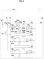
- Fig. 2 is a diagram showing an example of the DC microgrid system 1 showing a specific example of the configuration of the power converter 103 according to the first embodiment of the present disclosure.
- the voltage sensor 107 is shown in the DC microgrid system 1 shown in Fig. 2 .
- each of the plurality of power converters 103 includes a bridge circuit 103a, a capacitor 103b (an example of a second capacitor), a cutoff circuit 103c (an example of a first switching element), an energy absorption circuit 103d, a charging circuit 103e, a current sensor 103f, a voltage sensor 103g, a protective diode 103h, a braking circuit 103i, and a control circuit 103j (note that the protective diode 103h and the braking circuit 103i are shown in Figs. 8 to 14 described later).
- the bridge circuit 103a is a circuit that generates three-phase AC power from DC power.
- the bridge circuit 103a is configured by using, for example, a switching element such as a transistor.
- a switching element such as a transistor.
- the transistors include power semiconductor elements such as a SiC MOSFET (silicon carbide metal oxide semiconductor field effect transistor) or an IGBT (insulated gate bipolar transistor).
- the capacitor 103b smoothes the DC voltage input to the bridge circuit 103a.
- the cutoff circuit 103c disconnects the power converter 103 from the bus based on control by the control circuit 103j.
- Examples of the cutoff circuit 103c include power semiconductor elements such as a SiC MOSFET or an IGBT, and a physical switch.
- the energy absorption circuit 103d absorbs energy generated by a current flowing from the load to the power converter 103.
- the energy absorption circuit 103d includes a switching element 103d1, a resistor 103d2, and a capacitor 103d3.
- the switching element 103d1 turns to an ON state based on control by the control circuit 103j, and the energy absorption circuit 103d causes a current to flow according to a time constant determined by the resistor 103d2 and the capacitor 103d3, thereby preventing an increase in the DC voltage (that is, overvoltage) of the power converter 103 due to the regenerative power in the load of the power converter 103.
- the switching element 103d1 include a power semiconductor element such as a SiC MOSFET or an IGBT, and a physical switch.
- the charging circuit 103e is a circuit that absorbs the difference between the voltage on the bus side (that is, the potential difference between the positive electrode wire P and the negative electrode wire N) that may occur at the time of restart and the voltage at the input of the bridge circuit 103a (that is, the potential difference between both ends of the capacitor 103b) and limits the current flowing until the potential difference reaches zero.
- the charging circuit 103e includes, for example, a resistor 103e1 and a switching element 103e2 (an example of a third switching element).
- the current sensor 103f detects a current flowing from the bridge circuit 103a side to the bus side. For example, in a case where the positive electrode wire P and the negative electrode wire N of the bus are short-circuited, a current flows from the capacitor 103b toward the bus. The current sensor 103f detects the current.
- the voltage sensor 103g detects a voltage at the input of the bridge circuit 103a, that is, a potential difference between both ends of the capacitor 103b.
- the protective diode 103h allows a current to flow in a case where regenerative power is generated in the load of the power converter 103 and a short circuit occurs inside the bus or the power converter 103.
- the braking circuit 103i brakes, for example, a ship using the DC microgrid system 1 (that is, decelerates or stops the ship navigation).
- the braking circuit 103i includes a switching element 103i1 and a resistor 103i2.
- Examples of the switching element 103i1 include a power semiconductor element such as a SiC MOSFET or an IGBT, a physical switch, and the like (note that an IGBT is shown in Figs. 8 to 14 described later).
- the switching element 103i1 is in an OFF state in a case where deceleration or stopping of navigation is not performed, and is controlled to be in an ON state in a case where deceleration or stopping of navigation is performed.
- the resistor 103i2 sets how the brake works (that is, the degree of deceleration) according to the resistance value.
- the control circuit 103j controls the power converter 103.
- the control circuit 103j controls switching of the transistors in the bridge circuit 103a to generate AC power for driving the three-phase AC motor from DC power.
- the control circuit 103j controls each of switching elements 103c, 103d1, 103e2, and 103i1 to be in an ON state or an OFF state.
- control circuit 103j controls the switching element 103c to be in an ON state in a case where the current sensor 103f detects a current equal to or less than a predetermined threshold value, and controls the switching element 103c to be in an OFF state in a case where the current sensor 103f detects a current exceeding the predetermined threshold value.
- control circuit 103j controls the switching element 103c to be in an OFF state
- the control circuit 103j does not control the switching element 103c to be in an ON state until it is confirmed that the short circuit is improved (for example, until the potential difference between the positive electrode wire P and the negative electrode wire N of the bus is a desired potential difference and the potential difference between both ends of the capacitor 103b falls within a predetermined threshold value with respect to the desired potential difference).
- the control circuit 103j controls each of the switching elements 103c, 103d1, 103e2, and 103i1 to be in an ON state or an OFF state. Details of the control by the control circuit 103j for setting each of the switching elements 103c, 103d1, 103e2, and 103i1 to be in an ON state or an OFF state will be described later. In Figs. 8 to 14 described later, the control circuit 103j is not shown.
- the pre-charge sequence 105 controls the charging state in the initial operation of the generator G in the load 20a.
- the capacitor 106 stores an electric charge capable of disconnecting the bus tie fuses 101p and 101n. That is, as the capacitance of the capacitor 106, a capacitance capable of storing electric charges that can disconnect the bus tie fuses 101p and 101n is selected. For example, the capacitance is determined so that the square time product of the short-circuit current determined by the impedance of the short-circuit path and the resistance value inside the capacitor 106 exceeds the square time product of the short-circuit current of the bus tie fuses 101p and 101n.
- the voltage sensor 107 detects a potential difference between the positive electrode wire P and the negative electrode wire N of the bus, that is, a potential difference between both ends of the capacitor 106 via the bus tie fuses 101p and 101n.
- the load 20a is a load connected to each of the power converters 103 of the DC microgrid 10a.
- the load includes a motor that causes the ship to navigate, and regenerative power is generated by the motor.
- the DC microgrid 10b has the same configuration as the DC microgrid 10a.
- a load 20b is a load connected to each of the power converters 103 of the DC microgrid 10b.
- Fig. 1 shows an example in which the load 20b has the same configuration as that of the load 20a. However, the configuration of the load 20b may be different from that of the load 20a.
- Fig. 3 is a diagram showing an example of a first operation flow of the DC microgrid system 1 according to an embodiment of the present disclosure.
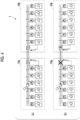
- Fig. 4 is a diagram showing an example of an image of a short circuit of a bus according to an embodiment of the present disclosure.
- the control circuit 103j controls each of the switching elements 103c to be in an ON state and each of switching elements 103d1, 103e2, and 103i1 to be in an OFF state. In this state, as shown in Fig. 4 , it is assumed that a short circuit occurs in the bus of the DC microgrid 10a.
- the current sensor 103f of each of the plurality of power converters 103 detects a current flowing from the capacitor 103b to the short-circuit point.
- the current sensor 103f outputs the value of the detected current to the control circuit 103j.
- the control circuit 103j compares the current value detected by the current sensor 103f with a predetermined threshold value.
- the control circuit 103j determines whether or not the current value detected by the current sensor 103f exceeds a threshold value (step S1).
- the threshold value is set to a current smaller than a current flowing to the short-circuit point as a current of the electric charge stored in the capacitor 103b. In this case, the control circuit 103j determines that all the currents detected by each of current sensors 103f exceed the threshold value.
- control circuit 103j determines that the current detected by the current sensor 103f exceeds the threshold value
- the control circuit 103j controls the switching element 103c connected to the current sensor 103f that has detected the current exceeding the threshold value to be in an OFF state (step S2).
- step S2 all the power converters 103 are disconnected from the bus.
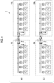
- Fig. 5 is a diagram showing an example of an image of a short circuit in the bridge circuit 103a according to an embodiment of the present disclosure.
- the control circuit 103j controls each of the switching elements 103c to be in an ON state and each of the switching elements 103d1, 103e2, and 103i1 to be in an OFF state. In this state, as shown in Fig. 5 , it is assumed that a short circuit occurs in one of bridge circuit 103a of the DC microgrid 10a.
- the current sensor 103f of each of the power converters 103 other than the power converter 103 in which the short circuit has occurred among the plurality of power converters 103 detects the current flowing from the capacitor 103b to the short-circuit point.
- the current detected by the current sensor 103f of the power converter 103 in which a short circuit has occurred is a current flowing into the power converter 103.
- the control circuit 103j does not change the operation.
- Each current sensor 103f outputs the value of the detected current to the control circuit 103j.
- the control circuit 103j compares the current value detected by the current sensor 103f with a predetermined threshold value.
- the control circuit 103j determines whether or not the current value detected by the current sensor 103f exceeds a threshold value (step S1).
- the threshold value is set to a current smaller than a current flowing to the short-circuit point as a current of the electric charge stored in the capacitor 103b, in this case, the control circuit 103j determines that all the currents detected by the current sensors 103f other than the current sensor 103f of the power converter 103 in which the short circuit has occurred exceed the threshold value.
- control circuit 103j determines that the current detected by the current sensor 103f exceeds the threshold value
- the control circuit 103j controls the switching element 103c connected to the current sensor 103f that has detected the current exceeding the threshold value to be in an OFF state (step S2).
- step S2 all the power converters 103 other than the power converter 103 in which the short circuit has occurred are disconnected from the bus.
- the capacitor 106 Since the capacitor 106 stores electric charges that can disconnect the bus tie fuses 101p and 101n, at least one of the bus tie fuses 101p and 101n is disconnected by the current flowing from the capacitor 106 toward the short-circuit point. As a result, the DC microgrid 10a in which a short circuit has occurred can be disconnected from the normal DC microgrid 10b.
- FIG. 6 is a diagram showing an example of an image of a short circuit in a connecting portion between DC microgrids (10a and 10b) according to an embodiment of the present disclosure.
- the control circuit 103j controls each of the switching elements 103c to be in an ON state and each of the switching elements 103d1, 103e2, and 103i1 to be in an OFF state. In this state, as shown in Fig. 6 , it is assumed that a short circuit occurs at the connecting portion between the DC microgrids 10a and 10b.
- the current sensor 103f of each of the plurality of power converters 103 detects a current flowing from the capacitor 103b to the short-circuit point.
- Each current sensor 103f outputs the value of the detected current to the control circuit 103j.
- the control circuit 103j compares the current value detected by the current sensor 103f with a predetermined threshold value.
- the control circuit 103j determines whether or not the current value detected by the current sensor 103f exceeds a threshold value (step S1).
- the threshold value is set to a current smaller than a current flowing to the short-circuit point as a current of the electric charge stored in the capacitor 103b, in this case, the control circuit 103j determines that all the currents detected by the current sensors 103f other than the current sensor 103f of the power converter 103 in which the short circuit has occurred exceed the threshold value.
- control circuit 103j determines that the current detected by the current sensor 103f exceeds the threshold value
- the control circuit 103j controls the switching element 103c connected to the current sensor 103f that has detected the current exceeding the threshold value to be in an OFF state (step S2).
- step S2 all the power converters 103 are disconnected from the bus.
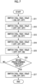
- Fig. 7 is a diagram showing an example of a second operation flow of the DC microgrid system 1 according to an embodiment of the present disclosure.
- Fig. 8 is a first diagram showing an example of transition of a state of a switching element according to an embodiment of the present disclosure.
- Fig. 9 is a second diagram showing an example of transition of a state of a switching element according to an embodiment of the present disclosure.
- Fig. 10 is a third diagram showing an example of the transition of the state of the switching element according to an embodiment of the present disclosure.
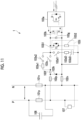
- Fig. 11 is a fourth diagram showing an example of the transition of the state of the switching element according to an embodiment of the present disclosure.
- Fig. 12 is a fifth diagram showing an example of the transition of the state of the switching element according to an embodiment of the present disclosure.
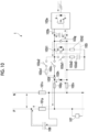
- Fig. 13 is a sixth diagram showing an example of transition of a state of a switching element according to an embodiment of the present disclosure.
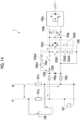
- Fig. 14 is a seventh diagram showing an example of transition of a state of a switching element according to an embodiment of the present disclosure.
- control circuit 103j controls the switching element 103c in the power converter 103 that drives the load in which the regenerative power is generated to be in an ON state and controls the switching elements 103d1, 103e2, and 103i1 to be in an OFF state.
- the switching element 103i1 in the power converter 103 that drives the load in which the regenerative power is generated is always in an OFF state in the following description.
- the control circuit 103j controls the switching element 103c of the power converter 103 in which the regenerative power is generated to be in an ON state and controls the switching elements 103d1 and 103e2 to be in an OFF state (step S11), as shown in Fig. 8 , the current flowing by the generated regenerative power flows from the output side to the input side inside the bridge circuit 103a, further flows to the bus via the current sensor 103f, the switching element 103c, and the fuse 102p, and returns as a return current from the bus to the bridge circuit 103a via the fuse 102n.
- the current flowing by the generated regenerative power is smaller than the current discharged from the capacitor 103b at the time of short circuit, and is a current having a value sufficiently smaller than the threshold value used when the control circuit 103j determines whether or not the current detected by the current sensor 103f exceeds the threshold value.
- a current for charging the capacitor 103b flows as shown in Fig. 11 due to energy stored in an inductor in the motor. Since there is no path through which this current flows other than the capacitor 103b, the charging of the capacitor 103b is continued until the energy stored in the inductor in the motor runs out. As a result, the voltage of the capacitor 103b rises. That is, the potential difference between both ends of the capacitor 103b increases.
- the voltage sensor 103g detects a potential difference between both ends of the capacitor 103b, and outputs the detected potential difference to the control circuit 103j.
- the control circuit 103j compares the potential difference detected by the voltage sensor 103g with a predetermined threshold value.
- the control circuit 103j determines whether or not the potential difference detected by the voltage sensor 103g exceeds a threshold value.
- the threshold value in this case is set to not exceed the rated voltage of the switching elements configuring the bridge circuit 103a.
- the control circuit 103j controls the switching element 103d1 to be in an OFF state in a case where the voltage sensor 103g detects a potential difference equal to or less than a threshold value, and controls the switching element 103d1 to be in an ON state in a case where the voltage sensor 103g detects a potential difference exceeding the threshold value.
- the maximum amount of the electric charge that can move from the capacitor 103b to the capacitor 103d3 is determined according to the ratio between the capacitance of the capacitor 103b and the capacitance of the capacitor 103d3.
- step S14 The operation of step S14 may be performed by the control device 104 after each of the voltage sensors 103g and 107 outputs the detection result to the control device 104.
- the control circuit 103j sets the switching element 103e2 to be in an ON state (step S15). Accordingly, the resistor 103e1 is provided in the path between the capacitor 106 and the capacitor 103b, and the resistor 103e1 absorbs the difference between the voltage on the bus side (that is, the potential difference between the positive electrode wire P and the negative electrode wire N) and the voltage at the input of the bridge circuit 103a (that is, the potential difference between both ends of the capacitor 103b).
- the control circuit 103j compares the detection result of each of the voltage sensors 103g and 107, and determines whether or not the difference indicated by the comparison result is within a predetermined threshold value (step S16). In a case where it is determined that the difference indicated by the comparison result is not within the predetermined threshold value (NO in step S 16), the control circuit 103j returns to the operation of step S16. In a case where the control circuit 103j determines that the difference indicated by the comparison result is within the predetermined threshold value (YES in step S16), the control circuit 103j controls the switching element 103c to be in an ON state and the switching element 103e2 to be in an OFF state as shown in Fig. 14 (step S17).
- step S17 may be performed in a case where a predetermined time elapses without performing the operation of step S16.
- the current sensor 103f is used to detect the current.
- the switching element 103c may be a semiconductor element and an increase in the current may be detected using a technology of non-saturation detection (so-called DESAT detection).
- the second fuse 101n has a first terminal connected to the negative electrode wire N of the bus to which the other DC microgrid 10b is connected, and a second terminal connected to the negative electrode wire N of the bus to which the plurality of power converters 103 are connected via the plurality of fuses 102n.
- the first capacitor 106 has a first terminal connected to the positive electrode wire P of the bus to which the other DC microgrid 10b is connected, a second terminal connected to the negative electrode wire N of the bus to which the other DC microgrid 10b is connected, and a capacitance capable of disconnecting at least one of the first fuse 101p and the second fuse 101n.
- the DC microgrid 10a in a case where the electric charge stored in the first capacitor 106 flows as a current toward the short-circuit point, the current flows from the first capacitor 106 to the short-circuit point via the first fuse 101p and the second fuse 101n.
- the first capacitor 106 has a capacitance capable of disconnecting at least one of the first fuse 101p and the second fuse 101n. Therefore, in a case where a current flows from the first capacitor 106 to the short-circuit point via the first fuse 101p and the second fuse 101n, at least one of the first fuse 101p and the second fuse 101n can be disconnected. As a result, the DC microgrid 10a can be disconnected from another DC microgrid 10b.
- control circuit 103j and other control devices may have a computer system therein.
- the above-described operation is stored in a computer-readable storage medium in the form of a program, and the operation is performed by a computer reading and executing the program.
- a specific example of the computer will be described below.
- the program may realize a part of the above-described functions. Furthermore, the program may be a so-called differential file (differential program) that can realize the above-described functions in combination with a program already recorded in the computer system.
- differential file differential program
- the DC microgrid 10a, the DC microgrid system 1, the control method, and the program according to each embodiment of the present disclosure are understood as follows, for example.
- the DC microgrid 10a includes a first capacitor 106 having a capacitance capable of disconnecting at least one of the first fuse 101p and the second fuse 101n.
- a DC microgrid 10a according to a second aspect is the DC 10a according to (1), in which the first terminal and the second terminal of the first capacitor 106 may be connected via the second fuse 101n.
- the fuse 101n can be disconnected when the connecting portion between the DC microgrids 10a and 10b is short-circuited.
- a DC microgrid 10a according to a third aspect is the DC microgrid 10a according to (1) or (2), in which each of the plurality of power converters 103 may include
- the DC microgrid 10a can disconnect the power converter 103 in which a short circuit has occurred from the bus.
- a DC microgrid 10a according to a fourth aspect is the DC microgrid 10a according to (3), further including
- the DC microgrid 10a can reduce the potential difference between both ends of the second capacitor 103b.
- a DC microgrid 10a according to a fifth aspect is the DC microgrid 10a according to (3) or (4), further including
- the DC microgrid 10a can absorb the potential difference by the resistor 103e1.
- the DC microgrid 10a can charge the first capacitor 106 via the second path.
- the DC microgrid 10a can set an appropriate potential in a case where restarting is performed.
- a DC microgrid system 1 includes
- the DC microgrid system 1 includes a first capacitor 106 having a capacitance capable of disconnecting at least one of the first fuse 101p and the second fuse 101n.
- the control method includes a first capacitor 106 having a capacitance capable of disconnecting at least one of the first fuse 101p and the second fuse 101n.
- a program according to an eighth aspect causing a computer (5) of a DC microgrid 10a including
- the program includes a first capacitor 106 having a capacitance capable of disconnecting at least one of the first fuse 101p and the second fuse 101n.
Landscapes
- Engineering & Computer Science (AREA)
- Power Engineering (AREA)
- Protection Of Static Devices (AREA)
- Direct Current Feeding And Distribution (AREA)
- Dc-Dc Converters (AREA)
- Inverter Devices (AREA)
Abstract
Description
- The present disclosure relates to a DC microgrid, a DC microgrid system, a control method, and a program.
- Priority is claimed on
Japanese Patent Application No. 2022-016516, filed Feb. 4, 2022 - As one aspect of supplying power to a plurality of loads, a DC microgrid system in which DC microgrids cooperate with each other has attracted attention in various fields.
PTLs 1 and 2 disclose a technology related to supplying power as a related technology. -
- [PTL 1]
Japanese Unexamined Patent Application Publication No. 2017-022973 - [PTL 2]
Japanese Unexamined Patent Application Publication No. 2006-129594 - In a limited space such as a ship, it is desired that an amount of power interchange between DC microgrids is large. Meanwhile, in a case where the DC microgrids are connected and cooperate with each other and a defect such as a short circuit has occurred, a fuse may be used to disconnect the DC microgrid in which the defect has occurred. As the fuse, a rated fuse capable of withstanding a large current is desired from the viewpoint of efficiently cooperating the DC microgrids. Meanwhile, in a case where a defect such as a short circuit has occurred, a rated fuse that is disconnected (fused) even with a small current is desired from the viewpoint of immediately disconnecting the DC microgrid in which the defect has occurred. That is, in a case where the DC microgrids are cooperated by being connected to each other via the fuse, there is a trade-off relationship between efficiently cooperating the DC microgrids and immediately disconnecting the DC microgrid in which the defect has occurred in a case where the defect has occurred, and it is generally difficult to achieve both of them. Therefore, in a DC microgrid system in which DC microgrids are connected to each other via a fuse to cooperate with each other, there is a demand for a technology capable of easily disconnecting the fuse in a case where a short circuit has occurred in the DC microgrid even in a case where rating of the fuse is increased.
- The present disclosure has been made to solve the above-described problem, and an object of the present disclosure is to provide a DC microgrid, a DC microgrid system, a control method, and a program capable of, easily disconnecting the fuse in a case where a short circuit has occurred in the DC microgrid even in a case where rating of the fuse is increased in a DC microgrid system in which DC microgrids are connected to each other via a fuse to cooperate with each other.
- In order to solve the above-described problem, a DC microgrid according to the present disclosure includes a first fuse having a first terminal connected to a positive electrode wire of a bus to which another cooperated DC microgrid is connected and a second terminal connected to a positive electrode wire of the bus to which a plurality of power converters are connected via a plurality of fuses, a second fuse having a first terminal connected to a negative electrode wire of the bus to which the other DC microgrid is connected and a second terminal connected to a negative electrode wire of the bus to which the plurality of power converters are connected via a plurality of fuses, and a first capacitor having a first terminal connected to the positive electrode wire of the bus to which the other DC microgrid is connected, a second terminal connected to the negative electrode wire of the bus to which the other DC microgrid is connected, and a capacitance capable of disconnecting (fusing) at least one of the first fuse and the second fuse.
- A DC microgrid system according to the present disclosure includes the DC microgrid and the other DC microgrid cooperating with the DC microgrid.
- A control method according to the present disclosure, performed by a DC microgrid including
- a first fuse having a first terminal connected to a positive electrode wire of a bus to which another cooperated DC microgrid is connected, and a second terminal connected to a positive electrode wire of the bus to which a plurality of power converters are connected via a plurality of fuses,
- a second fuse having a first terminal connected to a negative electrode wire of the bus to which the other DC microgrid is connected, and a second terminal connected to a negative electrode wire of the bus to which a plurality of power converters are connected via a plurality of fuses, and
- a first capacitor having a first terminal connected to a positive electrode wire of the bus to which the other DC microgrid is connected, a second terminal connected to a negative electrode wire of the bus to which the other DC microgrid is connected, and a capacitance in which at least one of the first fuse and the second fuse is disconnectable,
- in which each of the plurality of power converters includes
- a bridge circuit that generates AC power from DC power supplied from the positive electrode wire of the bus to which the plurality of power converters are connected and the negative electrode wire of the bus to which the plurality of power converters are connected,
- a second capacitor provided to be parallel with an input terminal of the bridge circuit and smoothing the DC power,
- a current sensor that detects a current flowing from the second capacitor to the bus in a case where the second capacitor discharges stored electric charge toward the bus, and
- a first switching element provided between the current sensor and the bus, the method includes
- determining whether or not the current detected by the current sensor exceeds a predetermined threshold value; and
- controlling the first switching element to be in an OFF state in a case where it is determined that the current detected by the current sensor exceeds the predetermined threshold value.
- A program according to the present disclosure causes a computer of a DC microgrid including
- a first fuse having a first terminal connected to a positive electrode wire of a bus to which another cooperated DC microgrid is connected, and a second terminal connected to a positive electrode wire of the bus to which a plurality of power converters are connected via a plurality of fuses,
- a second fuse having a first terminal connected to a negative electrode wire of the bus to which the other DC microgrid is connected, and a second terminal connected to a negative electrode wire of the bus to which a plurality of power converters are connected via a plurality of fuses, and
- a first capacitor having a first terminal connected to a positive electrode wire of the bus to which the other DC microgrid is connected, a second terminal connected to a negative electrode wire of the bus to which the other DC microgrid is connected, and a capacitance in which at least one of the first fuse and the second fuse is disconnectable,
- in which each of the plurality of power converters includes
- a bridge circuit that generates AC power from DC power supplied from the positive electrode wire of the bus to which the plurality of power converters are connected and the negative electrode wire of the bus to which the plurality of power converters are connected,
- a second capacitor provided to be parallel with an input terminal of the bridge circuit and smoothing the DC power,
- a current sensor that detects a current flowing from the second capacitor to the bus in a case where the second capacitor discharges stored electric charge toward the bus, and
a first switching element provided between the current sensor and the bus, to execute:- determining whether or not the current detected by the current sensor exceeds a predetermined threshold value; and
- controlling the first switching element to be in an OFF state in a case where it is determined that the current detected by the current sensor exceeds the predetermined threshold value.
- With the DC microgrid, the DC microgrid system, the control method, and the program according to the present disclosure, in the DC microgrid system in which the DC microgrids are connected to each other via the fuses to cooperate with each other, even in a case where the rating of the fuse is increased, it is possible to easily disconnect the fuse in a case where a short circuit has occurred in the DC microgrid.
-
-
Fig. 1 is a diagram showing an example of a configuration of a DC microgrid system according to an embodiment of the present disclosure. -
Fig. 2 is a diagram showing an example of aDC microgrid system 1 showing a specific example of a configuration of a power converter according to a first embodiment of the present disclosure. -
Fig. 3 is a diagram showing an example of a first operation flow of the DC microgrid system according to an embodiment of the present disclosure. -
Fig. 4 is a diagram showing an example of an image of a short circuit of a bus according to an embodiment of the present disclosure. -
Fig. 5 is a diagram showing an example of an image of a short circuit in a bridge circuit according to an embodiment of the present disclosure. -
Fig. 6 is a diagram showing an example of an image of a short circuit in a connecting portion between DC microgrids according to an embodiment of the present disclosure. -
Fig. 7 is a diagram showing an example of a second operation flow of the DC microgrid system according to an embodiment of the present disclosure. -
Fig. 8 is a first diagram showing an example of transition of a state of a switching element according to an embodiment of the present disclosure. -
Fig. 9 is a second diagram showing an example of the transition of the state of the switching element according to an embodiment of the present disclosure. -
Fig. 10 is a third diagram showing an example of the transition of the state of the switching element according to an embodiment of the present disclosure. -
Fig. 11 is a fourth diagram showing an example of the transition of the state of the switching element according to an embodiment of the present disclosure. -
Fig. 12 is a fifth diagram showing an example of the transition of the state of the switching element according to an embodiment of the present disclosure. -
Fig. 13 is a sixth diagram showing an example of the transition of the state of the switching element according to an embodiment of the present disclosure. -
Fig. 14 is a seventh diagram showing an example of the transition of the state of the switching element according to an embodiment of the present disclosure. -
Fig. 15 is a schematic block diagram showing a configuration of a computer according to at least one embodiment. - Hereinafter, embodiments will be described in detail with reference to the drawings. A DC microgrid system according to an embodiment of the present disclosure will be described.
-
Fig. 1 is a diagram showing an example of a configuration of aDC microgrid system 1 according to an embodiment of the present disclosure. As shown inFig. 1 , theDC microgrid system 1 includesDC microgrids DC microgrid system 1 is, for example, a system used in a ship. In theDC microgrid system 1, theDC microgrids DC microgrids DC microgrid system 1 is a system capable of disconnecting the system in which the short circuit occurs. - As shown in
Fig. 1 , theDC microgrid 10a includes bus tie fuses 101p (an example of a first fuse) and 101n (an example of a second fuse), a plurality offuses power converters 103, acontrol device 104, apre-charge sequence 105, a capacitor 106 (an example of a first capacitor), and a voltage sensor 107 (thevoltage sensor 107 is shown inFig. 2 to be described later). The number of each of thefuses power converters 103, and is six in the example shown inFig. 1 . - A
bus tie fuse 101p is a fuse provided in the positive electrode wire P of the bus in theDC microgrid system 1. Thebus tie fuse 101n is a fuse provided in the negative electrode wire N of the bus in theDC microgrid system 1. - As shown in
Fig. 1 , each of the plurality offuses 102p is provided between the positive electrode wire P and one of the plurality ofpower converters 103. As shown inFig. 1 , each of the plurality offuses 102n is provided between the negative electrode wire N and one of the plurality ofpower converters 103. - As shown in
Fig. 1 , each of the plurality ofpower converters 103 is connected to the positive electrode wire P via onefuse 102p. As shown inFig. 1 , each of the plurality ofpower converters 103 is connected to the negative electrode wire N via onefuse 102n. As shown inFig. 1 , each of the plurality ofpower converters 103 is connected to aload 20a. -
Fig. 2 is a diagram showing an example of theDC microgrid system 1 showing a specific example of the configuration of thepower converter 103 according to the first embodiment of the present disclosure. In theDC microgrid system 1 shown inFig. 2 , thevoltage sensor 107 is shown. - As shown in
Fig. 2 , each of the plurality ofpower converters 103 includes abridge circuit 103a, acapacitor 103b (an example of a second capacitor), acutoff circuit 103c (an example of a first switching element), anenergy absorption circuit 103d, acharging circuit 103e, acurrent sensor 103f, avoltage sensor 103g, aprotective diode 103h, abraking circuit 103i, and acontrol circuit 103j (note that theprotective diode 103h and thebraking circuit 103i are shown inFigs. 8 to 14 described later). - The
bridge circuit 103a is a circuit that generates three-phase AC power from DC power. Thebridge circuit 103a is configured by using, for example, a switching element such as a transistor. Examples of the transistors include power semiconductor elements such as a SiC MOSFET (silicon carbide metal oxide semiconductor field effect transistor) or an IGBT (insulated gate bipolar transistor). - The
capacitor 103b smoothes the DC voltage input to thebridge circuit 103a. In a case where thecurrent sensor 103f detects a current exceeding a predetermined threshold value, thecutoff circuit 103c disconnects thepower converter 103 from the bus based on control by thecontrol circuit 103j. Examples of thecutoff circuit 103c include power semiconductor elements such as a SiC MOSFET or an IGBT, and a physical switch. - In a case where regenerative power is generated in the load of the
power converter 103 and a short circuit occurs in the bus or thepower converter 103, theenergy absorption circuit 103d absorbs energy generated by a current flowing from the load to thepower converter 103. As shown inFig. 2 , theenergy absorption circuit 103d includes a switching element 103d1, a resistor 103d2, and a capacitor 103d3. In a case where regenerative power is generated in the load of thepower converter 103 and a short circuit occurs in the bus or inside thepower converter 103, the switching element 103d1 turns to an ON state based on control by thecontrol circuit 103j, and theenergy absorption circuit 103d causes a current to flow according to a time constant determined by the resistor 103d2 and the capacitor 103d3, thereby preventing an increase in the DC voltage (that is, overvoltage) of thepower converter 103 due to the regenerative power in the load of thepower converter 103. Examples of the switching element 103d1 include a power semiconductor element such as a SiC MOSFET or an IGBT, and a physical switch. - The charging
circuit 103e is a circuit that absorbs the difference between the voltage on the bus side (that is, the potential difference between the positive electrode wire P and the negative electrode wire N) that may occur at the time of restart and the voltage at the input of thebridge circuit 103a (that is, the potential difference between both ends of thecapacitor 103b) and limits the current flowing until the potential difference reaches zero. The chargingcircuit 103e includes, for example, a resistor 103e1 and a switching element 103e2 (an example of a third switching element). - The
current sensor 103f detects a current flowing from thebridge circuit 103a side to the bus side. For example, in a case where the positive electrode wire P and the negative electrode wire N of the bus are short-circuited, a current flows from thecapacitor 103b toward the bus. Thecurrent sensor 103f detects the current. - The
voltage sensor 103g detects a voltage at the input of thebridge circuit 103a, that is, a potential difference between both ends of thecapacitor 103b. Theprotective diode 103h allows a current to flow in a case where regenerative power is generated in the load of thepower converter 103 and a short circuit occurs inside the bus or thepower converter 103. - The
braking circuit 103i brakes, for example, a ship using the DC microgrid system 1 (that is, decelerates or stops the ship navigation). Thebraking circuit 103i includes a switching element 103i1 and a resistor 103i2. - Examples of the switching element 103i1 include a power semiconductor element such as a SiC MOSFET or an IGBT, a physical switch, and the like (note that an IGBT is shown in
Figs. 8 to 14 described later). The switching element 103i1 is in an OFF state in a case where deceleration or stopping of navigation is not performed, and is controlled to be in an ON state in a case where deceleration or stopping of navigation is performed. The resistor 103i2 sets how the brake works (that is, the degree of deceleration) according to the resistance value. - The
control circuit 103j controls thepower converter 103. For example, in a case where the load of thepower converter 103 is a three-phase AC motor, thecontrol circuit 103j controls switching of the transistors in thebridge circuit 103a to generate AC power for driving the three-phase AC motor from DC power. For example, thecontrol circuit 103j controls each of switchingelements 103c, 103d1, 103e2, and 103i1 to be in an ON state or an OFF state. Specifically, thecontrol circuit 103j controls the switchingelement 103c to be in an ON state in a case where thecurrent sensor 103f detects a current equal to or less than a predetermined threshold value, and controls the switchingelement 103c to be in an OFF state in a case where thecurrent sensor 103f detects a current exceeding the predetermined threshold value. In a case where thecontrol circuit 103j controls the switchingelement 103c to be in an OFF state, thecontrol circuit 103j does not control the switchingelement 103c to be in an ON state until it is confirmed that the short circuit is improved (for example, until the potential difference between the positive electrode wire P and the negative electrode wire N of the bus is a desired potential difference and the potential difference between both ends of thecapacitor 103b falls within a predetermined threshold value with respect to the desired potential difference). For example, in a case where regenerative power is generated in the load of thepower converter 103 and a short circuit occurs in the bus or inside thepower converter 103, thecontrol circuit 103j controls each of the switchingelements 103c, 103d1, 103e2, and 103i1 to be in an ON state or an OFF state. Details of the control by thecontrol circuit 103j for setting each of the switchingelements 103c, 103d1, 103e2, and 103i1 to be in an ON state or an OFF state will be described later. InFigs. 8 to 14 described later, thecontrol circuit 103j is not shown. - The
pre-charge sequence 105 controls the charging state in the initial operation of the generator G in theload 20a. Thecapacitor 106 stores an electric charge capable of disconnecting the bus tie fuses 101p and 101n. That is, as the capacitance of thecapacitor 106, a capacitance capable of storing electric charges that can disconnect the bus tie fuses 101p and 101n is selected. For example, the capacitance is determined so that the square time product of the short-circuit current determined by the impedance of the short-circuit path and the resistance value inside thecapacitor 106 exceeds the square time product of the short-circuit current of the bus tie fuses 101p and 101n. Thevoltage sensor 107 detects a potential difference between the positive electrode wire P and the negative electrode wire N of the bus, that is, a potential difference between both ends of thecapacitor 106 via the bus tie fuses 101p and 101n. - The
load 20a is a load connected to each of thepower converters 103 of theDC microgrid 10a. The load includes a motor that causes the ship to navigate, and regenerative power is generated by the motor. - The
DC microgrid 10b has the same configuration as theDC microgrid 10a. Aload 20b is a load connected to each of thepower converters 103 of theDC microgrid 10b.Fig. 1 shows an example in which theload 20b has the same configuration as that of theload 20a. However, the configuration of theload 20b may be different from that of theload 20a. - Next, an operation performed by the
DC microgrid system 1 will be described with reference toFigs. 3 to 14 . - First, an operation performed by the
DC microgrid system 1 in a case where the positive electrode wire P and the negative electrode wire N of the bus are short-circuited will be described with reference toFigs. 3 and4 .Fig. 3 is a diagram showing an example of a first operation flow of theDC microgrid system 1 according to an embodiment of the present disclosure.Fig. 4 is a diagram showing an example of an image of a short circuit of a bus according to an embodiment of the present disclosure. Here, it is assumed that thecontrol circuit 103j controls each of the switchingelements 103c to be in an ON state and each of switching elements 103d1, 103e2, and 103i1 to be in an OFF state. In this state, as shown inFig. 4 , it is assumed that a short circuit occurs in the bus of theDC microgrid 10a. - In this case, as shown in part (a) of
Fig. 4 , the electric charge stored in thecapacitor 103b of each of the plurality ofpower converters 103 included in theDC microgrids capacitors 106 included in theDC microgrids - The
current sensor 103f of each of the plurality ofpower converters 103 detects a current flowing from thecapacitor 103b to the short-circuit point. Thecurrent sensor 103f outputs the value of the detected current to thecontrol circuit 103j. Thecontrol circuit 103j compares the current value detected by thecurrent sensor 103f with a predetermined threshold value. Thecontrol circuit 103j determines whether or not the current value detected by thecurrent sensor 103f exceeds a threshold value (step S1). Specifically, the threshold value is set to a current smaller than a current flowing to the short-circuit point as a current of the electric charge stored in thecapacitor 103b. In this case, thecontrol circuit 103j determines that all the currents detected by each ofcurrent sensors 103f exceed the threshold value. - In a case where the
control circuit 103j determines that the current detected by thecurrent sensor 103f exceeds the threshold value, thecontrol circuit 103j controls the switchingelement 103c connected to thecurrent sensor 103f that has detected the current exceeding the threshold value to be in an OFF state (step S2). By this control, all thepower converters 103 are disconnected from the bus. - Even after all the
power converters 103 are disconnected from the bus, a current flows from thecapacitor 106 toward the short-circuit point until the electric charge stored in thecapacitor 106 is discharged. This current flows through thebus tie fuse 101p. Since thecapacitor 106 stores electric charges capable of disconnecting the bus tie fuses 101p and 101n, thebus tie fuse 101p is disconnected by the current flowing from thecapacitor 106 toward the short-circuit point. As a result, as shown in a part (b) ofFig. 4 , theDC microgrid 10a in which the short circuit has occurred can be disconnected from thenormal DC microgrid 10b. - Next, an operation performed by the
DC microgrid system 1 in a case where a short circuit occurs in thebridge circuit 103a of thepower converter 103 will be described with reference toFigs. 3 and5. Fig. 5 is a diagram showing an example of an image of a short circuit in thebridge circuit 103a according to an embodiment of the present disclosure. Here, it is assumed that thecontrol circuit 103j controls each of the switchingelements 103c to be in an ON state and each of the switching elements 103d1, 103e2, and 103i1 to be in an OFF state. In this state, as shown inFig. 5 , it is assumed that a short circuit occurs in one ofbridge circuit 103a of theDC microgrid 10a. - In this case, as shown in part (a) of
Fig. 5 , the electric charge stored in thecapacitor 103b of each of the plurality ofpower converters 103 included in theDC microgrids capacitors 106 included in theDC microgrids - The
current sensor 103f of each of thepower converters 103 other than thepower converter 103 in which the short circuit has occurred among the plurality ofpower converters 103 detects the current flowing from thecapacitor 103b to the short-circuit point. In addition, since a current flowing from the bus side to thebridge circuit 103a flows through thecurrent sensor 103f of thepower converter 103 in which a short circuit has occurred (in a case where a current is actually detected within an error range due to noise or measurement accuracy but can be ignored), the current detected by thecurrent sensor 103f of thepower converter 103 in which a short circuit has occurred is a current flowing into thepower converter 103. In a case where the current detected by thecurrent sensor 103f is the current flowing into thepower converter 103, thecontrol circuit 103j does not change the operation. - Each
current sensor 103f outputs the value of the detected current to thecontrol circuit 103j. Thecontrol circuit 103j compares the current value detected by thecurrent sensor 103f with a predetermined threshold value. Thecontrol circuit 103j determines whether or not the current value detected by thecurrent sensor 103f exceeds a threshold value (step S1). Specifically, the threshold value is set to a current smaller than a current flowing to the short-circuit point as a current of the electric charge stored in thecapacitor 103b, in this case, thecontrol circuit 103j determines that all the currents detected by thecurrent sensors 103f other than thecurrent sensor 103f of thepower converter 103 in which the short circuit has occurred exceed the threshold value. - In a case where the
control circuit 103j determines that the current detected by thecurrent sensor 103f exceeds the threshold value, thecontrol circuit 103j controls the switchingelement 103c connected to thecurrent sensor 103f that has detected the current exceeding the threshold value to be in an OFF state (step S2). By this control, all thepower converters 103 other than thepower converter 103 in which the short circuit has occurred are disconnected from the bus. - Even after all the
power converters 103 other than thepower converter 103 in which the short circuit has occurred are disconnected from the bus, a current flows from thecapacitor 106 toward the short-circuit point until the electric charge stored in thecapacitor 106 is discharged. This current flows through thebus tie fuse 101p and thefuses power converter 103 in which the short circuit has occurred. Since thefuses bus tie fuse 101p (and 101n), in this case, at least one of thefuses bus tie fuse 101p is disconnected (fused). Since thecapacitor 106 stores electric charges that can disconnect the bus tie fuses 101p and 101n, at least one of the bus tie fuses 101p and 101n is disconnected by the current flowing from thecapacitor 106 toward the short-circuit point. As a result, theDC microgrid 10a in which a short circuit has occurred can be disconnected from thenormal DC microgrid 10b. - Next, an operation performed by the
DC microgrid system 1 in a case where a short circuit occurs at the connecting portion between theDC microgrids Figs. 3 and6. Fig. 6 is a diagram showing an example of an image of a short circuit in a connecting portion between DC microgrids (10a and 10b) according to an embodiment of the present disclosure. Here, it is assumed that thecontrol circuit 103j controls each of the switchingelements 103c to be in an ON state and each of the switching elements 103d1, 103e2, and 103i1 to be in an OFF state. In this state, as shown inFig. 6 , it is assumed that a short circuit occurs at the connecting portion between theDC microgrids - In this case, as shown in part (a) of
Fig. 6 , the electric charge stored in thecapacitor 103b of each of the plurality ofpower converters 103 included in theDC microgrids capacitors 106 included in theDC microgrids - The
current sensor 103f of each of the plurality ofpower converters 103 detects a current flowing from thecapacitor 103b to the short-circuit point. - Each
current sensor 103f outputs the value of the detected current to thecontrol circuit 103j. Thecontrol circuit 103j compares the current value detected by thecurrent sensor 103f with a predetermined threshold value. Thecontrol circuit 103j determines whether or not the current value detected by thecurrent sensor 103f exceeds a threshold value (step S1). Specifically, the threshold value is set to a current smaller than a current flowing to the short-circuit point as a current of the electric charge stored in thecapacitor 103b, in this case, thecontrol circuit 103j determines that all the currents detected by thecurrent sensors 103f other than thecurrent sensor 103f of thepower converter 103 in which the short circuit has occurred exceed the threshold value. - In a case where the
control circuit 103j determines that the current detected by thecurrent sensor 103f exceeds the threshold value, thecontrol circuit 103j controls the switchingelement 103c connected to thecurrent sensor 103f that has detected the current exceeding the threshold value to be in an OFF state (step S2). By this control, all thepower converters 103 are disconnected from the bus. - Even after all the
power converters 103 are disconnected from the bus, a current flows from thecapacitor 106 toward the short-circuit point until the electric charge stored in thecapacitor 106 is discharged. This current flows through thebus tie fuse 101n. In this case, thebus tie fuse 101n is disconnected (fused). As a result, theDC microgrids - Next, an operation performed by the
DC microgrid system 1 in a case where regenerative power is generated in the load of thepower converter 103 and a short circuit occurs in the bus will be described with reference toFigs. 7 to 14 . Examples of the load in this case include a three-phase AC motor.Fig. 7 is a diagram showing an example of a second operation flow of theDC microgrid system 1 according to an embodiment of the present disclosure.Fig. 8 is a first diagram showing an example of transition of a state of a switching element according to an embodiment of the present disclosure.Fig. 9 is a second diagram showing an example of transition of a state of a switching element according to an embodiment of the present disclosure.Fig. 10 is a third diagram showing an example of the transition of the state of the switching element according to an embodiment of the present disclosure.Fig. 11 is a fourth diagram showing an example of the transition of the state of the switching element according to an embodiment of the present disclosure.Fig. 12 is a fifth diagram showing an example of the transition of the state of the switching element according to an embodiment of the present disclosure.Fig. 13 is a sixth diagram showing an example of transition of a state of a switching element according to an embodiment of the present disclosure.Fig. 14 is a seventh diagram showing an example of transition of a state of a switching element according to an embodiment of the present disclosure. Here, it is assumed that thecontrol circuit 103j controls the switchingelement 103c in thepower converter 103 that drives the load in which the regenerative power is generated to be in an ON state and controls the switching elements 103d1, 103e2, and 103i1 to be in an OFF state. The switching element 103i1 in thepower converter 103 that drives the load in which the regenerative power is generated is always in an OFF state in the following description. - In a case where the
control circuit 103j controls the switchingelement 103c of thepower converter 103 in which the regenerative power is generated to be in an ON state and controls the switching elements 103d1 and 103e2 to be in an OFF state (step S11), as shown inFig. 8 , the current flowing by the generated regenerative power flows from the output side to the input side inside thebridge circuit 103a, further flows to the bus via thecurrent sensor 103f, the switchingelement 103c, and thefuse 102p, and returns as a return current from the bus to thebridge circuit 103a via thefuse 102n. The current flowing by the generated regenerative power is smaller than the current discharged from thecapacitor 103b at the time of short circuit, and is a current having a value sufficiently smaller than the threshold value used when thecontrol circuit 103j determines whether or not the current detected by thecurrent sensor 103f exceeds the threshold value. - In this state, as shown in
Fig. 9 , it is assumed that a short circuit occurs in the bus. In this case, as shown inFig. 9 , the current flowing due to the generated regenerative power flows toward the short-circuit point, and the electric charge stored in each ofcapacitors capacitor 103b flows to the short-circuit point as a current, thecontrol circuit 103j determines that the current detected by thecurrent sensor 103f exceeds the threshold value, and controls the switchingelement 103c to be in an OFF state (step S12). - When the
switching element 103c turns to an OFF state, a current flows via theprotective diode 103h as shown inFig. 10 . Since theswitching element 103c turns to an OFF state, the current caused by the generated regenerative power flowing from thebridge circuit 103a to the bus via theswitching element 103c and thefuse 102p does not flow. - However, in a case where the load is a motor, a current for charging the
capacitor 103b flows as shown inFig. 11 due to energy stored in an inductor in the motor. Since there is no path through which this current flows other than thecapacitor 103b, the charging of thecapacitor 103b is continued until the energy stored in the inductor in the motor runs out. As a result, the voltage of thecapacitor 103b rises. That is, the potential difference between both ends of thecapacitor 103b increases. Thevoltage sensor 103g detects a potential difference between both ends of thecapacitor 103b, and outputs the detected potential difference to thecontrol circuit 103j. Thecontrol circuit 103j compares the potential difference detected by thevoltage sensor 103g with a predetermined threshold value. Thecontrol circuit 103j determines whether or not the potential difference detected by thevoltage sensor 103g exceeds a threshold value. For example, the threshold value in this case is set to not exceed the rated voltage of the switching elements configuring thebridge circuit 103a. Thecontrol circuit 103j controls the switching element 103d1 to be in an OFF state in a case where thevoltage sensor 103g detects a potential difference equal to or less than a threshold value, and controls the switching element 103d1 to be in an ON state in a case where thevoltage sensor 103g detects a potential difference exceeding the threshold value. - In a case where the
voltage sensor 103g detects a potential difference exceeding the threshold value and thecontrol circuit 103j controls the switching element 103d1 to be in an ON state (step S13), as shown inFig. 12 , the electric charge stored in thecapacitor 103b flows through theenergy absorption circuit 103d as a current. When the current flows through theenergy absorption circuit 103d, the potential difference between both ends of thecapacitor 103b decreases. Since this current is determined by the resistance value of the resistor 103d2, the maximum current is suppressed. In this state, since thecapacitor 103b and the capacitor 103d3 are connected to be parallel with each other, the maximum amount of the electric charge that can move from thecapacitor 103b to the capacitor 103d3 is determined according to the ratio between the capacitance of thecapacitor 103b and the capacitance of the capacitor 103d3. - Each of
voltage sensors control circuit 103j. Therefore, thecontrol circuit 103j knows the detection result of each of thevoltage sensors capacitor 103b reaches to be equal to or less than the predetermined potential difference, thecontrol circuit 103j controls the switching element 103d1 to be in an OFF state as shown inFig. 13 (step S14). The operation of step S14 may be performed by thecontrol device 104 after each of thevoltage sensors control device 104. When the operation of step S14 is performed, there is a possibility that the potential difference between the positive electrode wire P and the negative electrode wire N of the bus (that is, the potential difference between both ends of the capacitor 106) and the potential difference between both ends of thecapacitor 103b are deviated by a predetermined threshold value or more. - Therefore, the
control circuit 103j sets the switching element 103e2 to be in an ON state (step S15). Accordingly, the resistor 103e1 is provided in the path between thecapacitor 106 and thecapacitor 103b, and the resistor 103e1 absorbs the difference between the voltage on the bus side (that is, the potential difference between the positive electrode wire P and the negative electrode wire N) and the voltage at the input of thebridge circuit 103a (that is, the potential difference between both ends of thecapacitor 103b). - The
control circuit 103j compares the detection result of each of thevoltage sensors control circuit 103j returns to the operation of step S16. In a case where thecontrol circuit 103j determines that the difference indicated by the comparison result is within the predetermined threshold value (YES in step S16), thecontrol circuit 103j controls the switchingelement 103c to be in an ON state and the switching element 103e2 to be in an OFF state as shown inFig. 14 (step S17). - In the
DC microgrid system 1 according to another embodiment of the present disclosure, the operation of step S17 may be performed in a case where a predetermined time elapses without performing the operation of step S16. - In addition, in an embodiment of the present disclosure described above, the
current sensor 103f is used to detect the current. However, in another embodiment of the present disclosure, the switchingelement 103c may be a semiconductor element and an increase in the current may be detected using a technology of non-saturation detection (so-called DESAT detection). - The
DC microgrid system 1 according to an embodiment of the present disclosure has been described above. In theDC microgrid system 1, theDC microgrid 10a includes afirst fuse 101p, asecond fuse 101n, and afirst capacitor 106. The first terminal of thefirst fuse 101p is connected to the positive electrode wire P of the bus to which another cooperatedDC microgrid 10b is connected, and the second terminal of thefirst fuse 101p is connected to the positive electrode wire P of the bus to which the plurality ofpower converters 103 are connected via the plurality offuses 102p. Thesecond fuse 101n has a first terminal connected to the negative electrode wire N of the bus to which the other DC microgrid 10b is connected, and a second terminal connected to the negative electrode wire N of the bus to which the plurality ofpower converters 103 are connected via the plurality offuses 102n. Thefirst capacitor 106 has a first terminal connected to the positive electrode wire P of the bus to which the other DC microgrid 10b is connected, a second terminal connected to the negative electrode wire N of the bus to which the other DC microgrid 10b is connected, and a capacitance capable of disconnecting at least one of thefirst fuse 101p and thesecond fuse 101n. - Thus, in the
DC microgrid system 1, in a case where the electric charge stored in thefirst capacitor 106 flows as a current toward the short-circuit point, the current flows from thefirst capacitor 106 to the short-circuit point via thefirst fuse 101p and thesecond fuse 101n. Thefirst capacitor 106 has a capacitance capable of disconnecting at least one of thefirst fuse 101p and thesecond fuse 101n. Therefore, in a case where a current flows from thefirst capacitor 106 to the short-circuit point via thefirst fuse 101p and thesecond fuse 101n, at least one of thefirst fuse 101p and thesecond fuse 101n can be disconnected. As a result, theDC microgrid 10a can be disconnected from anotherDC microgrid 10b. - Note that the order of the operation in the embodiment of the present disclosure may be changed as long as appropriate operation is performed.
- Each of the storage unit and the storage device (including a register and a latch) in the embodiment of the present disclosure may be provided anywhere within a range in which transmission and reception of appropriate information are performed. A plurality of each of the storage unit or the storage device may be provided as long as appropriate information is transmitted and received, and data may be stored in a distributed manner.
- Although the embodiments of the present disclosure have been described, the above-described
control circuit 103j and other control devices may have a computer system therein. The above-described operation is stored in a computer-readable storage medium in the form of a program, and the operation is performed by a computer reading and executing the program. A specific example of the computer will be described below. -
Fig. 15 is a schematic block diagram showing a configuration of a computer according to at least one exemplary embodiment. As shown inFig. 15 , acomputer 5 includes a CPU6, amain memory 7, astorage 8, and an interface 9. For example, each of the above-describedcontrol circuit 103j and other control devices is mounted on thecomputer 5. The operation of each processing unit described above is stored in thestorage 8 in the form of a program. The CPU6 reads the program from thestorage 8, develops the program in themain memory 7, and executes the above-described operation according to the program. The CPU6 secures a storage area corresponding to each of the above-described storage units in themain memory 7 according to the program. - Examples of the
storage 8 include a hard disk drive (HDD), a solid state drive (SSD), a magnetic disk, a magneto-optical disk, a compact disc read only memory (CD-ROM), a digital versatile disc read only memory (DVD-ROM), and a semiconductor memory such as a flash memory. Thestorage 8 may be an internal medium directly connected to a bus of thecomputer 5, or may be an external medium connected to thecomputer 5 via the interface 9 or a communication line. In a case where the program is distributed to thecomputer 5 through a communication line, thecomputer 5 that has received the distribution may develop the program in themain memory 7 and execute the above-described operation. In at least one embodiment, thestorage 8 is a non-transitory tangible storage medium. - The program may realize a part of the above-described functions. Furthermore, the program may be a so-called differential file (differential program) that can realize the above-described functions in combination with a program already recorded in the computer system.
- While certain embodiments according to the present disclosure have been described, these embodiments have been presented by way of example only, and are not intended to limit the scope of the disclosure. Various additions, various omissions, various substitutions, and various modifications may be made to these embodiments without departing from the scope of the disclosure.
- The
DC microgrid 10a, theDC microgrid system 1, the control method, and the program according to each embodiment of the present disclosure are understood as follows, for example. -
- (1) A
DC microgrid 10a according to a first aspect includes- a
first fuse 101p having a first terminal connected to a positive electrode wire P of a bus to which another cooperatedDC microgrid 10b is connected, and a second terminal connected to a positive electrode wire P of the bus to which a plurality ofpower converters 103 are connected via a plurality offuses 102p, - a
second fuse 101n having a first terminal connected to a negative electrode wire N of the bus to which the anotherDC microgrid 10b is connected, and a second terminal connected to a negative electrode wire N of the bus to which a plurality ofpower converters 103 are connected via a plurality offuses 102n, and - a
first capacitor 106 having a first terminal connected to a positive electrode w ire P of the bus to which the other DC microgrid 10b is connected, a second terminal c onnected to a negative electrode wire N of the bus to which the other DC microgrid 10 b is connected, and a capacitance in which at least one of thefirst fuse 101p and the second fuse 101n is disconnectable.
- a
- The
DC microgrid 10a includes afirst capacitor 106 having a capacitance capable of disconnecting at least one of thefirst fuse 101p and thesecond fuse 101n. Thus, in the DC microgrid system in which theDC microgrids fuses fuses DC microgrid 10a can easily disconnect thefuses DC microgrid 10a. - (2) A
DC microgrid 10a according to a second aspect is theDC 10a according to (1),
in which the first terminal and the second terminal of thefirst capacitor 106 may be connected via thesecond fuse 101n. - As a result, in the
DC microgrid 10a, thefuse 101n can be disconnected when the connecting portion between theDC microgrids - (3) A
DC microgrid 10a according to a third aspect is theDC microgrid 10a according to (1) or (2),
in which each of the plurality ofpower converters 103 may include - a
bridge circuit 103a for generating AC power from DC power supplied from a positive electrode wire P of the bus to which the plurality ofpower converters 103 are connected and a negative electrode wire N of the bus to which the plurality ofpower converters 103 are connected, - a
second capacitor 103b provided to be parallel with an input terminal of thebridge circuit 103a for smoothing the DC power, - a
current sensor 103f for detecting a current flowing from thesecond capacitor 103b to the bus in a case where thesecond capacitor 103b discharges the stored electric charge toward the bus, - a
first switching element 103c provided between thecurrent sensor 103f and the bus, and - a
control device 104 for determining whether or not the current detected by thecurrent sensor 103f exceeds a predetermined threshold value, and controlling thefirst switching element 103c to be in an OFF state in a case where it is determined that the current detected by thecurrent sensor 103f exceeds the predetermined threshold value. - Thus, the
DC microgrid 10a can disconnect thepower converter 103 in which a short circuit has occurred from the bus. - (4) A
DC microgrid 10a according to a fourth aspect is theDC microgrid 10a according to (3), further including - a first path provided to be parallel with the
second capacitor 103b, having a second switching element 103d1, turning to a conduction state in a case where the second switching element 103d1 turns to an ON state, and turning to a disconnection state in a case where the second switching element 103d1 turns to an OFF state, - in which the
control device 104 may be configured to control thefirst switching element 103c to be in an OFF state in a case where regenerative power is generated in a load of thepower converter 103, and control the second switching element 103d1 to be in an ON state in a case where a path of a current flowing due to generation of the regenerative power is only thesecond capacitor 103b. - Thus, the
DC microgrid 10a can reduce the potential difference between both ends of thesecond capacitor 103b. - (5) A
DC microgrid 10a according to a fifth aspect is theDC microgrid 10a according to (3) or (4), further including - a second path provided to be parallel with the
first switching element 103c and having a third switching element 103e2 and a resistor 103e1 connected in series with the third switching element 103e2, - in which the
control device 104 may be configured to control thefirst switching element 103c to be in an OFF state and control the third switching element 103e2 to be in an ON state in a case where it is determined that comparison result between the potential difference between both ends of thefirst capacitor 106 and the potential difference between both ends of thesecond capacitor 103b is within a range of the predetermined threshold value. - Thus, even in a case where the potential difference between the positive electrode wire P and the negative electrode wire N of the bus (that is, the potential difference between both ends of the capacitor 106) is different from the potential difference between both ends of the
capacitor 103b, theDC microgrid 10a can absorb the potential difference by the resistor 103e1. In addition, theDC microgrid 10a can charge thefirst capacitor 106 via the second path. As a result, theDC microgrid 10a can set an appropriate potential in a case where restarting is performed. - (6) A
DC microgrid system 1 according to a sixth aspect includes - the
DC microgrid 10a according to any one of (1) to (5), and - the other DC microgrid 10b cooperating with the
DC microgrid 10a. - The
DC microgrid system 1 includes afirst capacitor 106 having a capacitance capable of disconnecting at least one of thefirst fuse 101p and thesecond fuse 101n. Thus, in theDC microgrid system 1 in which theDC microgrids fuses fuses DC microgrid system 1 can easily disconnect thefuses DC microgrid 10a. - (7) A control method according to a seventh aspect, performed by a
DC microgrid 10a including - a
first fuse 101p having a first terminal connected to a positive electrode wire P of a bus to which another cooperatedDC microgrid 10b is connected, and a second terminal connected to a positive electrode wire P of the bus to which a plurality ofpower converters 103 are connected via a plurality offuses 102p, - a
second fuse 101n having a first terminal connected to a negative electrode wire N of the bus to which the anotherDC microgrid 10b is connected, and a second terminal connected to a negative electrode wire N of the bus to which a plurality ofpower converters 103 are connected via a plurality offuses 102n, and - a
first capacitor 106 having a first terminal connected to a positive electrode wire P of the bus to which the other DC microgrid 10b is connected and a second terminal connected to a negative electrode wire N of the bus to which the other DC microgrid 10b is connected, and a capacitance in which at least one of thefirst fuse 101p and thesecond fuse 101n is disconnectable, - in which each of the plurality of
power converters 103 includes- a
bridge circuit 103a for generating AC power from DC power supplied from a positive electrode wire P of the bus to which the plurality ofpower converters 103 are connected and a negative electrode wire N of the bus to which the plurality ofpower converters 103 are connected, - a
second capacitor 103b provided to be parallel with an input terminal of thebridge circuit 103a for smoothing the DC power, - a
current sensor 103f for detecting a current flowing from thesecond capacitor 103b to the bus in a case where thesecond capacitor 103b discharges the stored electric charge toward the bus, and - a
first switching element 103c provided between thecurrent sensor 103f and the bus, the method includes
- a
- determining whether or not the current detected by the
current sensor 103f exceeds a predetermined threshold value; and - controlling the
first switching element 103c to be in an OFF state in a case where it is determined that the current detected by thecurrent sensor 103f exceeds the predetermined threshold value. - The control method includes a
first capacitor 106 having a capacitance capable of disconnecting at least one of thefirst fuse 101p and thesecond fuse 101n. Thus, in the control method, in theDC microgrid system 1 in which theDC microgrids fuses fuses fuses DC microgrid 10a. - (8) A program according to an eighth aspect causing a computer (5) of a
DC microgrid 10a including - a
first fuse 101p having a first terminal connected to a positive electrode wire P of a bus to which another cooperatedDC microgrid 10b is connected, and a second terminal connected to a positive electrode wire P of the bus to which a plurality ofpower converters 103 are connected via a plurality offuses 102p, - a
second fuse 101n having a first terminal connected to a negative electrode wire N of the bus to which the anotherDC microgrid 10b is connected, and a second terminal connected to a negative electrode wire N of the bus to which a plurality ofpower converters 103 are connected via a plurality offuses 102n, and - a
first capacitor 106 having a first terminal connected to a positive electrode wire P of the bus to which the other DC microgrid 10b is connected and a second terminal connected to a negative electrode wire N of the bus to which the other DC microgrid 10b is connected, and a capacitance in which at least one of thefirst fuse 101p and thesecond fuse 101n is disconnectable, - in which each of the plurality of
power converters 103 includes- a
bridge circuit 103a for generating AC power from DC power supplied from a positive electrode wire P of the bus to which the plurality ofpower converters 103 are connected and a negative electrode wire N of the bus to which the plurality ofpower converters 103 are connected, - a
second capacitor 103b provided to be parallel with an input terminal of thebridge circuit 103a for smoothing the DC power, - a
current sensor 103f for detecting a current flowing from thesecond capacitor 103b to the bus in a case where thesecond capacitor 103b discharges the stored electric charge toward the bus, and - a
first switching element 103c provided between thecurrent sensor 103f and the bus, to execute:- determining whether or not the current detected by the
current sensor 103f exceeds a predetermined threshold value; and - controlling the
first switching element 103c to be in an OFF state in a case wh ere it is determined that the current detected by thecurrent sensor 103f exceeds the pre determined threshold value.
- determining whether or not the current detected by the
- a
- The program includes a
first capacitor 106 having a capacitance capable of disconnecting at least one of thefirst fuse 101p and thesecond fuse 101n. Thus, in theDC microgrid system 1 in which theDC microgrids fuses fuses fuses DC microgrid 10a. - With the DC microgrid, the DC microgrid system, the control method, and the program according to the present disclosure, in the DC microgrid system in which the DC microgrids are connected to each other via the fuses to cooperate with each other, even in a case where the rating of the fuse is increased, it is possible to easily disconnect the fuse in a case where a short circuit has occurred in the DC microgrid.
-
- 1: DC microgrid system
- 5: computer
- 6: CPU
- 7: main memory
- 8: storage
- 9: interface
- 10a, 10b: DC microgrid
- 20a, 20b: load
- 101p, 101n, 102p, 102n: fuse
- 103: power converter
- 103a: bridge circuit
- 103b, 103d3, 106: capacitor
- 103c, 103d1, 103e2: switching element
- 103d: energy absorption circuit
- 103d2, 103e1: resistor
- 103e: charging circuit
- 103f: current sensor
- 103g, 107: voltage sensor
- 104: control device
- 105: pre-charge sequence
Claims (8)
- A DC microgrid comprising:a first fuse having a first terminal connected to a positive electrode wire of a b us to which another cooperated DC microgrid is connected, and a second terminal con nected to a positive electrode wire of the bus to which a plurality of power converters a re connected via a plurality of fuses;a second fuse having a first terminal connected to a negative electrode wire of the bus to which the other DC microgrid is connected, and a second terminal connecte d to a negative electrode wire of the bus to which a plurality of power converters are c onnected via a plurality of fuses; anda first capacitor having a first terminal connected to a positive electrode wire o f the bus to which the other DC microgrid is connected, a second terminal connected to a negative electrode wire of the bus to which the other DC microgrid is connected, an d a capacitance in which at least one of the first fuse and the second fuse is disconnect able.
- The DC microgrid according to Claim 1,
wherein the first terminal and the second terminal of the first capacitor are con nected via the second fuse. - The DC microgrid according to Claim 1 or 2,
wherein each of the plurality of power converters includesa bridge circuit that generates AC power from DC power supplied from the positive electrode wire of the bus to which the plurality of power converters are connected and the negative electrode wire of the bus to which the plurality of power converters are connected,a second capacitor provided to be parallel with an input terminal of the bridge circuit and smoothing the DC power,a current sensor that detects a current flowing from the second capacitor to the bus in a case where the second capacitor discharges stored electric charge toward the bus,a first switching element provided between the current sensor and the bus, anda control device that determines whether or not the current detected by the current sensor exceeds a predetermined threshold value, and controls the first switching element to be in an OFF state in a case where it is determined that the current detected by the current sensor exceeds the predetermined threshold value. - The DC microgrid according to Claim 3, further comprising:a first path provided to be parallel with the second capacitor, having a second s witching element, turning to a conduction state in a case where the second switching el ement turns to an ON state, and turning to a disconnection state in a case where the sec ond switching element turns to an OFF state,wherein in the control device, regenerative power is generated in a load of the power converter, the first switching element is controlled to be in an OFF state, and the second switching element is controlled to be in an ON state in a case where a path of a current flowing due to the generation of the regenerative power is only the second ca pacitor.
- The DC microgrid according to Claim 3 or 4, further comprising:a second path provided to be parallel with the first switching element, and havi ng a third switching element and a resistor connected in series with the third switching element,wherein the control device controls the first switching element to be in an OFF state and controls the third switching element to be in an ON state in a case where it i s determined that a comparison result between a potential difference between both end s of the first capacitor and a potential difference between both ends of the second capa citor is within a range of the predetermined threshold value.
- A DC microgrid system comprising:the DC microgrid according to any one of Claims 1 to 5; andthe other DC microgrid cooperating with the DC microgrid.
- A control method, performed by a DC micro grid includinga first fuse having a first terminal connected to a positive electrode wire of a bus to which another cooperated DC microgrid is connected, and a second terminal connected to a positive electrode wire of the bus to which a plurality of power converters are connected via a plurality of fuses,a second fuse having a first terminal connected to a negative electrode wire of the bus to which the other DC microgrid is connected, and a second terminal connected to a negative electrode wire of the bus to which a plurality of power converters are connected via a plurality of fuses, anda first capacitor having a first terminal connected to a positive electrode wire of the bus to which the other DC microgrid is connected, a second terminal connected to a negative electrode wire of the bus to which the other DC microgrid is connected, and a capacitance in which at least one of the first fuse and the second fuse is disconnectable,in which each of the plurality of power converters includesa bridge circuit that generates AC power from DC power supplied from the positive electrode wire of the bus to which the plurality of power converters are connected and the negative electrode wire of the bus to which the plurality of power converters are connected,a second capacitor provided to be parallel with an input terminal of the bridge circuit and smoothing the DC power,a current sensor that detects a current flowing from the second capacitor to the bus in a case where the second capacitor discharges stored electric charge toward the bus, anda first switching element provided between the current sensor and the bus, the method comprising:determining whether or not the current detected by the current sensor exceeds a predetermined threshold value; andcontrolling the first switching element to be in an OFF state in a case where it is determined that the current detected by the current sensor exceeds the predetermined threshold value.
- A program causing a computer of a DC microgrid includinga first fuse having a first terminal connected to a positive electrode wire of a bus to which another cooperated DC microgrid is connected, and a second terminal connected to a positive electrode wire of the bus to which a plurality of power converters are connected via a plurality of fuses,a second fuse having a first terminal connected to a negative electrode wire of the bus to which the other DC microgrid is connected, and a second terminal connected to a negative electrode wire of the bus to which a plurality of power converters are connected via a plurality of fuses, anda first capacitor having a first terminal connected to a positive electrode wire of the bus to which the other DC microgrid is connected, a second terminal connected to a negative electrode wire of the bus to which the other DC microgrid is connected, and a capacitance in which at least one of the first fuse and the second fuse is disconnectable,in which each of the plurality of power converters includesa bridge circuit that generates AC power from DC power supplied from the positive electrode wire of the bus to which the plurality of power converters are connected and the negative electrode wire of the bus to which the plurality of power converters are connected,a second capacitor provided to be parallel with an input terminal of the bridge circuit and smoothing the DC power,a current sensor that detects a current flowing from the second capacitor to the bus in a case where the second capacitor discharges stored electric charge toward the bus, anda first switching element provided between the current sensor and the bus, to execute:determining whether or not the current detected by the current sensor exceeds a predetermined threshold value; andcontrolling the first switching element to be in an OFF state in a case where it is determined that the current detected by the current sensor exceeds the predetermined threshold value.
Applications Claiming Priority (2)
| Application Number | Priority Date | Filing Date | Title |
|---|---|---|---|
| JP2022016516A JP7851136B2 (en) | 2022-02-04 | 2022-02-04 | DC microgrid, DC microgrid system, control method, and program |
| PCT/JP2022/040424 WO2023149032A1 (en) | 2022-02-04 | 2022-10-28 | Dc microgrid, dc microgrid system, control method, and program |
Publications (2)
| Publication Number | Publication Date |
|---|---|
| EP4472002A1 true EP4472002A1 (en) | 2024-12-04 |
| EP4472002A4 EP4472002A4 (en) | 2025-05-14 |
Family
ID=87552121
Family Applications (1)
| Application Number | Title | Priority Date | Filing Date |
|---|---|---|---|
| EP22924937.0A Pending EP4472002A4 (en) | 2022-02-04 | 2022-10-28 | DC MICRO GRID, DC MICRO GRID SYSTEM, CONTROL METHOD AND PROGRAM |
Country Status (3)
| Country | Link |
|---|---|
| EP (1) | EP4472002A4 (en) |
| JP (1) | JP7851136B2 (en) |
| WO (1) | WO2023149032A1 (en) |
Families Citing this family (1)
| Publication number | Priority date | Publication date | Assignee | Title |
|---|---|---|---|---|
| WO2025181962A1 (en) * | 2024-02-28 | 2025-09-04 | Ntt株式会社 | Device and power supply system |
Family Cites Families (7)
| Publication number | Priority date | Publication date | Assignee | Title |
|---|---|---|---|---|
| JP2006129594A (en) | 2004-10-28 | 2006-05-18 | Hitachi Ltd | Method and apparatus for controlling marine electric propulsion device |
| ES2552857T3 (en) | 2012-02-29 | 2015-12-02 | Abb Technology Ltd | A DC power system with system protection capabilities |
| CA2932102C (en) | 2015-06-10 | 2024-04-30 | Rolls-Royce Corporation | Fault identification and isolation in an electric propulsion system |
| EP3890094A4 (en) | 2018-11-29 | 2022-05-11 | Honda Motor Co., Ltd. | BATTERY USAGE SYSTEM, CHARGER DEVICE, INFORMATION PROCESSING DEVICE, BATTERY USAGE METHOD, PROGRAM, AND INFORMATION HOLDER |
| CN111585270B (en) | 2020-05-29 | 2024-03-26 | 西安中车永电电气有限公司 | Marine direct current grid-connected system and simulation method for short-circuit protection of marine direct current grid-connected system |
| CN112615358B (en) | 2020-12-22 | 2024-10-22 | 武汉船用电力推进装置研究所(中国船舶重工集团公司第七一二研究所) | Ship direct-current networking electric propulsion system and short-circuit fault rapid protection method |
| CN113644723B (en) * | 2021-08-24 | 2024-10-25 | 西安中车永电电气有限公司 | A shipboard power distribution system with electromagnetic interference suppression function |
-
2022
- 2022-02-04 JP JP2022016516A patent/JP7851136B2/en active Active
- 2022-10-28 EP EP22924937.0A patent/EP4472002A4/en active Pending
- 2022-10-28 WO PCT/JP2022/040424 patent/WO2023149032A1/en not_active Ceased
Also Published As
| Publication number | Publication date |
|---|---|
| WO2023149032A1 (en) | 2023-08-10 |
| JP7851136B2 (en) | 2026-04-24 |
| JP2023114249A (en) | 2023-08-17 |
| EP4472002A4 (en) | 2025-05-14 |
Similar Documents
| Publication | Publication Date | Title |
|---|---|---|
| JP5622978B1 (en) | DC power transmission system protection system, AC / DC converter, and DC power transmission system disconnection method | |
| RU2584096C2 (en) | Direct voltage power switch | |
| JP6183460B2 (en) | Inverter device | |
| US20210091660A1 (en) | Power conversion device | |
| EP3468026B1 (en) | Power converter | |
| US11368101B2 (en) | Power conversion system | |
| JP4942169B2 (en) | 3-level inverter | |
| JP7851136B2 (en) | DC microgrid, DC microgrid system, control method, and program | |
| US12255546B2 (en) | Power conversion device that converts electric power between DC circuit and AC circuit | |
| JP2020058205A (en) | Switch drive | |
| JPH06327262A (en) | Inverter protector | |
| CN113228492A (en) | Composite power conversion system | |
| CN112054683B (en) | Power conversion device | |
| JP7702896B2 (en) | Charging system, charging method, and program | |
| JP5185563B2 (en) | Power converter | |
| CN111264024A (en) | Inverter device, its control circuit, and motor drive system | |
| JP7442749B1 (en) | power converter | |
| JP6552113B2 (en) | Power converter | |
| US12294291B2 (en) | Power conversion system | |
| JP7195488B1 (en) | power control system | |
| JP6833546B2 (en) | Power converter and power conversion method | |
| JP2025067140A (en) | Electric power conversion device | |
| JP2024032386A (en) | power converter | |
| JP2002330595A (en) | Motor control device | |
| JP2001028881A (en) | Voltage type inverter circuit |
Legal Events
| Date | Code | Title | Description |
|---|---|---|---|
| STAA | Information on the status of an ep patent application or granted ep patent |
Free format text: STATUS: THE INTERNATIONAL PUBLICATION HAS BEEN MADE |
|
| PUAI | Public reference made under article 153(3) epc to a published international application that has entered the european phase |
Free format text: ORIGINAL CODE: 0009012 |
|
| STAA | Information on the status of an ep patent application or granted ep patent |
Free format text: STATUS: REQUEST FOR EXAMINATION WAS MADE |
|
| 17P | Request for examination filed |
Effective date: 20240830 |
|
| AK | Designated contracting states |
Kind code of ref document: A1 Designated state(s): AL AT BE BG CH CY CZ DE DK EE ES FI FR GB GR HR HU IE IS IT LI LT LU LV MC ME MK MT NL NO PL PT RO RS SE SI SK SM TR |
|
| REG | Reference to a national code |
Ref country code: DE Ref legal event code: R079 Free format text: PREVIOUS MAIN CLASS: H02H0007000000 Ipc: H02H0007122000 |
|
| A4 | Supplementary search report drawn up and despatched |
Effective date: 20250415 |
|
| DAV | Request for validation of the european patent (deleted) | ||
| DAX | Request for extension of the european patent (deleted) | ||
| RIC1 | Information provided on ipc code assigned before grant |
Ipc: H02H 7/26 20060101ALI20250409BHEP Ipc: H02J 1/00 20060101ALI20250409BHEP Ipc: H02H 7/122 20060101AFI20250409BHEP |