EP4471978A1 - Spaceborne antenna with rolling flex hinges and associates methods - Google Patents
Spaceborne antenna with rolling flex hinges and associates methods Download PDFInfo
- Publication number
- EP4471978A1 EP4471978A1 EP24177511.3A EP24177511A EP4471978A1 EP 4471978 A1 EP4471978 A1 EP 4471978A1 EP 24177511 A EP24177511 A EP 24177511A EP 4471978 A1 EP4471978 A1 EP 4471978A1
- Authority
- EP
- European Patent Office
- Prior art keywords
- hinge
- antenna
- rolling
- coupled
- linkage
- Prior art date
- Legal status (The legal status is an assumption and is not a legal conclusion. Google has not performed a legal analysis and makes no representation as to the accuracy of the status listed.)
- Pending
Links
Images




Classifications
-
- H—ELECTRICITY
- H01—ELECTRIC ELEMENTS
- H01Q—ANTENNAS, i.e. RADIO AERIALS
- H01Q3/00—Arrangements for changing or varying the orientation or the shape of the directional pattern of the waves radiated from an antenna or antenna system
- H01Q3/02—Arrangements for changing or varying the orientation or the shape of the directional pattern of the waves radiated from an antenna or antenna system using mechanical movement of antenna or antenna system as a whole
- H01Q3/04—Arrangements for changing or varying the orientation or the shape of the directional pattern of the waves radiated from an antenna or antenna system using mechanical movement of antenna or antenna system as a whole for varying one co-ordinate of the orientation
-
- B—PERFORMING OPERATIONS; TRANSPORTING
- B64—AIRCRAFT; AVIATION; COSMONAUTICS
- B64G—COSMONAUTICS; VEHICLES OR EQUIPMENT THEREFOR
- B64G1/00—Cosmonautic vehicles
- B64G1/22—Parts of, or equipment specially adapted for fitting in or to, cosmonautic vehicles
- B64G1/222—Parts of, or equipment specially adapted for fitting in or to, cosmonautic vehicles for deploying structures between a stowed and deployed state
-
- E—FIXED CONSTRUCTIONS
- E05—LOCKS; KEYS; WINDOW OR DOOR FITTINGS; SAFES
- E05F—DEVICES FOR MOVING WINGS INTO OPEN OR CLOSED POSITION; CHECKS FOR WINGS; WING FITTINGS NOT OTHERWISE PROVIDED FOR, CONCERNED WITH THE FUNCTIONING OF THE WING
- E05F1/00—Closers or openers for wings, not otherwise provided for in this subclass
- E05F1/08—Closers or openers for wings, not otherwise provided for in this subclass spring-actuated, e.g. for horizontally sliding wings
- E05F1/10—Closers or openers for wings, not otherwise provided for in this subclass spring-actuated, e.g. for horizontally sliding wings for swinging wings, e.g. counterbalance
- E05F1/12—Mechanisms in the shape of hinges or pivots, operated by springs
- E05F1/1284—Mechanisms in the shape of hinges or pivots, operated by springs with a leaf or similar spring
-
- F—MECHANICAL ENGINEERING; LIGHTING; HEATING; WEAPONS; BLASTING
- F16—ENGINEERING ELEMENTS AND UNITS; GENERAL MEASURES FOR PRODUCING AND MAINTAINING EFFECTIVE FUNCTIONING OF MACHINES OR INSTALLATIONS; THERMAL INSULATION IN GENERAL
- F16C—SHAFTS; FLEXIBLE SHAFTS; ELEMENTS OR CRANKSHAFT MECHANISMS; ROTARY BODIES OTHER THAN GEARING ELEMENTS; BEARINGS
- F16C11/00—Pivots; Pivotal connections
- F16C11/04—Pivotal connections
- F16C11/10—Arrangements for locking
-
- H—ELECTRICITY
- H01—ELECTRIC ELEMENTS
- H01Q—ANTENNAS, i.e. RADIO AERIALS
- H01Q1/00—Details of, or arrangements associated with, antennas
- H01Q1/08—Means for collapsing antennas or parts thereof
-
- H—ELECTRICITY
- H01—ELECTRIC ELEMENTS
- H01Q—ANTENNAS, i.e. RADIO AERIALS
- H01Q1/00—Details of, or arrangements associated with, antennas
- H01Q1/12—Supports; Mounting means
- H01Q1/1235—Collapsible supports; Means for erecting a rigid antenna
-
- H—ELECTRICITY
- H01—ELECTRIC ELEMENTS
- H01Q—ANTENNAS, i.e. RADIO AERIALS
- H01Q1/00—Details of, or arrangements associated with, antennas
- H01Q1/27—Adaptation for use in or on movable bodies
- H01Q1/28—Adaptation for use in or on aircraft, missiles, satellites, or balloons
- H01Q1/288—Satellite antennas
-
- H—ELECTRICITY
- H01—ELECTRIC ELEMENTS
- H01Q—ANTENNAS, i.e. RADIO AERIALS
- H01Q15/00—Devices for reflection, refraction, diffraction or polarisation of waves radiated from an antenna, e.g. quasi-optical devices
- H01Q15/14—Reflecting surfaces; Equivalent structures
- H01Q15/16—Reflecting surfaces; Equivalent structures curved in two dimensions [2D], e.g. paraboloidal
- H01Q15/161—Collapsible reflectors
-
- E—FIXED CONSTRUCTIONS
- E05—LOCKS; KEYS; WINDOW OR DOOR FITTINGS; SAFES
- E05Y—INDEXING SCHEME ASSOCIATED WITH SUBCLASSES E05D AND E05F, RELATING TO CONSTRUCTION ELEMENTS, ELECTRIC CONTROL, POWER SUPPLY, POWER SIGNAL OR TRANSMISSION, USER INTERFACES, MOUNTING OR COUPLING, DETAILS, ACCESSORIES, AUXILIARY OPERATIONS NOT OTHERWISE PROVIDED FOR, APPLICATION THEREOF
- E05Y2900/00—Application of doors, windows, wings or fittings thereof
- E05Y2900/50—Application of doors, windows, wings or fittings thereof for vehicles
- E05Y2900/502—Application of doors, windows, wings or fittings thereof for vehicles for aircraft or spacecraft
-
- F—MECHANICAL ENGINEERING; LIGHTING; HEATING; WEAPONS; BLASTING
- F16—ENGINEERING ELEMENTS AND UNITS; GENERAL MEASURES FOR PRODUCING AND MAINTAINING EFFECTIVE FUNCTIONING OF MACHINES OR INSTALLATIONS; THERMAL INSULATION IN GENERAL
- F16C—SHAFTS; FLEXIBLE SHAFTS; ELEMENTS OR CRANKSHAFT MECHANISMS; ROTARY BODIES OTHER THAN GEARING ELEMENTS; BEARINGS
- F16C11/00—Pivots; Pivotal connections
- F16C11/04—Pivotal connections
- F16C11/045—Pivotal connections with at least a pair of arms pivoting relatively to at least one other arm, all arms being mounted on one pin
-
- F—MECHANICAL ENGINEERING; LIGHTING; HEATING; WEAPONS; BLASTING
- F16—ENGINEERING ELEMENTS AND UNITS; GENERAL MEASURES FOR PRODUCING AND MAINTAINING EFFECTIVE FUNCTIONING OF MACHINES OR INSTALLATIONS; THERMAL INSULATION IN GENERAL
- F16C—SHAFTS; FLEXIBLE SHAFTS; ELEMENTS OR CRANKSHAFT MECHANISMS; ROTARY BODIES OTHER THAN GEARING ELEMENTS; BEARINGS
- F16C2326/00—Articles relating to transporting
- F16C2326/47—Cosmonautic vehicles, i.e. bearings adapted for use in outer-space
-
- F—MECHANICAL ENGINEERING; LIGHTING; HEATING; WEAPONS; BLASTING
- F16—ENGINEERING ELEMENTS AND UNITS; GENERAL MEASURES FOR PRODUCING AND MAINTAINING EFFECTIVE FUNCTIONING OF MACHINES OR INSTALLATIONS; THERMAL INSULATION IN GENERAL
- F16C—SHAFTS; FLEXIBLE SHAFTS; ELEMENTS OR CRANKSHAFT MECHANISMS; ROTARY BODIES OTHER THAN GEARING ELEMENTS; BEARINGS
- F16C2380/00—Electrical apparatus
Definitions
- the present disclosure relates to spaceborne antennas for a satellite, and more particularly, to a rolling flex hinge used in a spaceborne antenna having a stored position and a deployed position.
- Transitioning antenna structures from a collapsed form to a fully deployed shape is based upon the use of hinges and other mechanisms to fold the mechanical structures that support the feeds and reflective surfaces of large antennas.
- Such antennas may also need to be stiff in their deployed shape to allow spacecraft maneuvering and maintain a precise antenna geometry.
- Cords are used between rigid structures to form tension truss structures that are both stiff and very lightweight.
- a spaceborne antenna for a satellite may comprise a plurality of antenna sections for the satellite, and at least one rolling flex hinge rotatably coupling first and second antenna sections together and permitting rotation between a stored position and a deployed position.
- the first and second antenna sections may be stacked in the stored position and extended in end-to-end relation in the deployed position.
- the at least one rolling flex hinge may comprise a first hinge body coupled to an end of the first antenna section, a second hinge body coupled to an end of the second antenna section, an a flexible strap arrangement coupling the first hinge body and second hinge body together to permit rolling contact therebetween.
- At least one locking linkage may be coupled between the first and second hinge bodies to lock the first and second hinge bodies when the first and second antenna sections are in the deployed position.
- the at least one locking linkage may comprise a plurality of spaced apart locking linkages.
- Each locking linkage may comprise a first linkage pivotally coupled to the first hinge body, and a second linkage pivotally coupled to the second hinge body.
- the first and second linkages may be pivotally coupled together.
- Each locking linkage may comprise a first magnet carried by the first linkage, and a second magnet carried by the second linkage.
- the first and second magnets couple together to lock the first and second hinge bodies when the first and second antenna sections are in the deployed position.
- the at least one rolling flex hinge may comprise a stop to stop the rolling contact between the first and second hinge bodies when the first and second hinge bodies are locked.
- the stop may comprise a dowel pin carried by a rolling surface of the first hinge body, and a set screw carried by a rolling surface of the second hinge body. The set screw contacts the dowel pin when the first and second antenna sections are in the deployed position.
- the flexible strap arrangement may comprise at least one first flexible strap coupled between the first and second hinges, and at least one second flexible strap coupled between the first and second hinges and non-overlapping with the at least one first flexible strap.
- the respective rolling surfaces of the first and second hinge bodies may include respective grooves for receiving the at least one first and second flexible straps.
- the at least one rolling flex hinge may comprise a plurality of spaced apart rolling flex hinges rotatably coupling the first and second antenna sections together.
- the rolling flex hinge permits rotation of the first and second antenna sections between a stored position and a deployed position.
- the rolling flex hinge may include a first hinge body coupled to an end of the first antenna section, a second hinge body coupled to an end of the second antenna section, and a flexible strap arrangement coupling the first hinge body and second hinge body together to permit rolling contact therebetween.
- the first and second antenna sections may be stacked in the stored position and extended in end-to-end relation in the deployed position.
- At least one locking linkage may be coupled between the first and second hinge bodies to lock the first and second hinge bodies when the first and second antenna sections are in the deployed position.
- Yet another aspect is directed to a method for making a rolling flex hinge for a spaceborne antenna as described above.
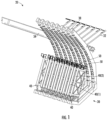
- FIGS. 1 and 2 a spaceborne antenna 30 for a satellite 20 will be discussed.
- a partial perspective view of the spaceborne antenna 30 in a stored position is provided in FIG. 1
- a partial top view of the spaceborne antenna 30 in a deployed position is provided in FIG. 2 .
- the spaceborne antenna 30 includes at least one telescoping boom 34 carried by a support structure.
- the telescoping boom 34 includes a plurality of telescoping sections 36 which can collapse the spaceborne antenna 30 to the stored position or expand the spaceborne antenna 30 to the deployed position.
- the bulkheads 38 structurally support one or more flexible elements so as to provide a parabolic trough shaped surface when the telescoping boom 34 is expanded.
- the flexible elements are not shown to simplify the figures.
- the bulkheads 38 carry a plurality of antenna sections 40.
- Each antenna section 40 includes one or more radiating elements to form an array.
- radiating elements are arranged to face a concave surface of the parabolic trough shaped surface that is intended to concentrate RF energy in a desired pattern.
- the radiating elements can include, but are not limited to, patch antennas, dipole antennas, monopole antennas, horns, and helical coils.
- a size of the antenna sections 40 may depend on a desired footprint of the satellite antenna 30.
- each antenna section 40 may be 40 inches in length, 3.25 inches in width and 1.5 inch in thickness. In other embodiments, the antenna sections 40 may be larger or smaller as needed to support the desired footprint of the satellite antenna 30.
- the antenna sections 40 include first and second antenna sections 40(1), 40(2) positioned between adjacent bulkheads 38. One end of the first antenna section 40(1) is pivotally coupled to one of the bulkheads 38, and one end of the second antenna section 40(2) is pivotally coupled to the adjacent bulkhead 38, as best shown in the deployed position in FIG. 2 .
- a pair of rolling flex hinges 50 rotatably couple the first and second antenna sections 40(1), 40(2) together.
- the rolling flex hinges 50 permit rotation of the first and second antenna sections 40(1), 40(2) between the stored position and the deployed position.
- the rolling flex hinges 50 advantageously lock in position without exceeding a final locked dimension to avoid overstretching components associated with the satellite antenna 30.
- rolling flex hinge 50 is being discussed for a satellite antenna 30, this particular application is not to be limiting.
- the rolling flex hinge 50 may be used in other applications where a zero-overstretch hinge that locks on a center position is needed.
- each rolling flex hinge 50 includes a first hinge body 52 to be coupled to an end of the first antenna section 40(1), and a second hinge body 54 to be coupled to an end of the second antenna section 40(2).
- a flexible strap arrangement 60 couples the first hinge body 52 and the second hinge body 54 together to permit rolling contact therebetween.
- At least one locking linkage 72 is coupled between the first and second hinge bodies 52, 54 to lock the first and second hinge bodies when the first and second antenna sections 40(1), 40(2) are in the deployed position.
- Each locking linkage 72 is on a side of the first and second hinge bodies 52, 54 to stop rolling contact when in the deployed positon.
- Each locking linkage 72 includes a first linkage 74(1) pivotally coupled to the first hinge body 52, and a second linkage 74(2) pivotally coupled to the second hinge body 54.
- the first and second linkages 74(1), 74(2) are pivotally coupled together.
- a shoulder bolt 80 and nut 81 may be used to pivotally couple the first and second linkages 74(1), 74(2) together.
- Shoulder bolts 82 may be used to pivotally couple the first linkage 74(1) to the first hinge body 52 and to pivotally couple the second linkage 74(2) to the second hinge body 54.
- Each locking linkage 72 includes magnets 78 so that the first and second linkages 74(1), 74(2) stop on center but still have a significant retaining force in the locked position. This helps to maintain an alignment positon between the first and second hinge bodies 52, 54 in the locked positon.
- Interface 73 is formed by respective surfaces of the first and second linkages 74(1), 74(2) when in the locked positon.
- the magnets 78 are positioned to make contact or couple together when the interface 73 is formed.
- Each rolling flex hinge 50 includes an adjustable hard stop 90 at the top of the rolling surface between the first and second hinge bodies 52, 54.
- the hard stop 90 may also be referred to as a stop.
- An enlarged cross-sectional view 92 of the hard stop 90 is illustrated in FIG. 4 .
- the hard stop 90 is configured to stop the rolling contact between the first and second hinge bodies 52, 54 when the first and second hinge bodies are in the locked positon.
- the locking linkages 72 in the locked positon advantageously provide a wide base for bending loads through the rolling flex hinge 50 when opposed with the hard stop 90.
- the hard stop 90 includes a dowel pin 94 carried by a rolling surface of the first hinge body 52.
- a set screw 96 is carried by a rolling surface of the second hinge body 54. The set screw 96 contacts the dowel pin 94 when the first and second antenna sections 40(1), 40(2) are in the deployed position.
- the set screw 96 is movable to adjust stoppage of the rolling contact between the first and second hinge bodies 52, 54.
- the hard stop 90 as illustrated is not to be limiting as other hard stop arrangements may be used for stoppage of the rolling contact between the first and second hinge bodies 52, 54.
- the flexible strap arrangement 60 includes a plurality of flexible straps 62, 64(1), 64(2) coupled between the first and second hinges 52, 54.
- the rolling flex hinge 50 has a curved interface surface between the first and second hinge bodies 52, 54 such that the hinges roll past each other.
- the flexible straps 62, 64(1), 64(2) are positioned within grooves on the curved interface surface. This forms tracks on either side of each hinge body 52, 54.
- the tracks with the flexible straps 62, 64(1), 64(2) provide an interface for the rolling contact between the first and second hinge bodies 52, 54.
- the tracks also provide alignment between the first and second hinge bodies 52, 54.
- the grooves allow the flexible straps 62, 64(1), 64(2) to be recessed while permitting rolling contact between the first and second hinge bodies 52, 54.
- the flexible straps 62, 64(1), 64(2) prevent the first and second hinge bodies 52, 54 from separating.
- flexible strap 62 is configured as a single wide strap, and flexible straps 64(1), 64(2) are configured as a pair of spaced apart narrow straps.
- the flexible straps 62, 64(1), 64(2) are positioned to be non-overlapping.
- the wide flexible strap 62 may also be configured as a pair of narrow straps, for example.
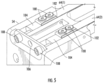
- FIG. 5 Connection of the flexible straps 64(1), 64(2) to the second hinge body 54 is shown in FIG. 5 .
- a pair of shoulder bolts 100 are used to secure ends of the flexible straps 64(1), 64(2) to the second hinge body 54.
- the ends of the flexible straps 64(1), 64(2) wrap around respective plate washers 102.
- FIG. 6 Connection of the flexible straps 64(1), 64(2) to the first hinge body 52 is shown in FIG. 6 .
- a pair of shoulder bolts 100 are used to secure ends of the flexible straps 64(1), 64(2) to the first hinge body 52.
- the ends of the flexible straps 64(1), 64(2) also wrap around respective plate washers 102.
- tension of the flexible straps 64(1), 64(2) may be adjusted using tensioning bolts 108.
- the tensioning bolts 108 extend through a plate washer 106 and into tensioning blocks 104 that are associated with ends of the flexible straps 64(1), 64(2).
- Connection of flexible strap 62 to the first and second hinge bodies 52, 54 is similar to that of flexible straps 64(1), 64(2).
- the deployment axis 130 extends between adjacent bulkheads 38, and is defined by the connection points 122 of the first and second antenna panels 40(1), 40(2) to the respective bulkheads 78.
- the mid-hinge contact point 120 is the point of contact between the first and second hinge bodies 52, 54 during rotation of the rolling flex hinge 50.
- the mid-hinge contact point 120 needs to stay above the deployment axis 130.
- the deployment axis 130 remains the same in the different deployment positions.
- the deployment length 126 changes in the different deployment positions.
- the antenna panels 40(1), 40(2) are in the stored position in FIG. 7A .
- the mid-hinge contact point 120 is a maximum distance from the deployment axis 130 in the stored position, whereas the deployment length 126 is at a minimum in the stored position.
- the mid-hinge contact point 120 moves closer to the deployment axis 130.
- the antenna panels 40(1), 40(2) are very close to the deployed position in FIG. 7B . In this position, movement of the antenna panels 40(1), 40(2) is about 95% of the deployed position.
- the mid-hinge contact point 120 remains above the deployment axis 130.
- the antenna panels 40(1), 40(2) are 100% deployed in FIG. 7C .
- the deployment length 126 is at a maximum, and the mid-hinge contact point 120 is at a minimum but still above the deployment axis 130. Since the mid-hinge contact point 120 does not cross the deployment axis 130, a zero-over stretch condition for the rolling flex hinge 50 is met. This means the maximum deployment length 126 occurs at 100% deployment of the first and second antenna panels 40(1), 40(2).
- the method includes providing a first hinge body 52 to be coupled to an end of the first antenna section 40(1) at Block 204, and providing a second hinge body 54 to be coupled to an end of the second antenna section 40(2) at Block 206.
- the first hinge body 52 and second hinge body 54 are coupled together at Block 208 using a flexible strap arrangement 60 to permit rolling contact therebetween.
- the first and second hinge bodies 52, 54 may be coupled together before being connected to the first and second antenna sections 40(1), 40(2).
- the first and second antenna sections 40(1), 40(2) are stacked in the stored position and are extended in end-to-end relation in the deployed position.
- At least one locking linkage 72 is coupled between the first and second hinge bodies 52, 54 at Block 210 to lock the first and second hinge bodies 52, 54 when the first and second antenna sections 40(1), 40(2) are in the deployed position.
- the method ends at Block 212.
- the rolling flex hinge 50 is not limited to spaceborne antennas 30. In addition to deployable antenna panels 40(1), 40(2), other types of spaceborne elements may be used with the rolling flex hinge 50.
- the deployable elements may be solar panel sections or optical reflector panel sections, for example.
- the rolling flex hinge 50 permits rotation of first and second elements between a stored position and a deployed position.
- the first and second elements may need to be stiff in their deployed shape to allow spacecraft maneuvering and maintain a precise geometry.
- Cords 32 may be used between rigid structures to form tension truss structures that are both stiff and very lightweight.
- the rolling flex hinge 50 advantageously deploys and locks in position the first and second elements without exceeding a final locked dimension to avoid overstretching the tension truss structures.
Landscapes
- Engineering & Computer Science (AREA)
- Physics & Mathematics (AREA)
- Remote Sensing (AREA)
- Astronomy & Astrophysics (AREA)
- General Physics & Mathematics (AREA)
- Aviation & Aerospace Engineering (AREA)
- General Engineering & Computer Science (AREA)
- Mechanical Engineering (AREA)
- Electromagnetism (AREA)
- Aerials With Secondary Devices (AREA)
Abstract
A spaceborne antenna (30) for a satellite (20) may include antenna sections (40) for the satellite (20), and at least one rolling flex hinge (50) rotatably coupling first and second antenna sections (40(1), 40(2)) together and permitting rotation between a stored position and a deployed position. The first and second antenna sections (40(1), 40(2)) may be stacked in the stored position and extended in end-to-end relation in the deployed position. The at least one rolling flex hinge (50) may include a first hinge body (52) coupled to an end of the first antenna section (40(1)), a second hinge body (54) coupled to an end of the second antenna section (40(2)), and a flexible strap arrangement (60) coupling the first hinge body (52) and second hinge body (54) together to permit rolling contact therebetween. At least one locking linkage (72) may be coupled between the first and second hinge bodies (52, 54) to lock the first and second hinge bodies (52, 54) when the first and second antenna sections (40(1), 40(2)) are in the deployed position.
Description
- The present disclosure relates to spaceborne antennas for a satellite, and more particularly, to a rolling flex hinge used in a spaceborne antenna having a stored position and a deployed position.
- Large spaceborne antennas often need to be collapsed to a compact form to fit in the constrained volume of a launch vehicle. Transitioning antenna structures from a collapsed form to a fully deployed shape is based upon the use of hinges and other mechanisms to fold the mechanical structures that support the feeds and reflective surfaces of large antennas.
- Such antennas may also need to be stiff in their deployed shape to allow spacecraft maneuvering and maintain a precise antenna geometry. Cords are used between rigid structures to form tension truss structures that are both stiff and very lightweight.
- In such instances, it may be desirable to have a rotation axis between two stiff structures that deploys and locks in position without exceeding the final locked dimension to avoid overstretching other components. In addition, when multiple panels with significant thickness are folded back and forth, it may be desirable to be able to deploy the panels without gaps between adjacent panels.
- A spaceborne antenna for a satellite may comprise a plurality of antenna sections for the satellite, and at least one rolling flex hinge rotatably coupling first and second antenna sections together and permitting rotation between a stored position and a deployed position. The first and second antenna sections may be stacked in the stored position and extended in end-to-end relation in the deployed position.
- The at least one rolling flex hinge may comprise a first hinge body coupled to an end of the first antenna section, a second hinge body coupled to an end of the second antenna section, an a flexible strap arrangement coupling the first hinge body and second hinge body together to permit rolling contact therebetween. At least one locking linkage may be coupled between the first and second hinge bodies to lock the first and second hinge bodies when the first and second antenna sections are in the deployed position.
- The at least one locking linkage may comprise a plurality of spaced apart locking linkages. Each locking linkage may comprise a first linkage pivotally coupled to the first hinge body, and a second linkage pivotally coupled to the second hinge body. The first and second linkages may be pivotally coupled together.
- Each locking linkage may comprise a first magnet carried by the first linkage, and a second magnet carried by the second linkage. The first and second magnets couple together to lock the first and second hinge bodies when the first and second antenna sections are in the deployed position.
- The at least one rolling flex hinge may comprise a stop to stop the rolling contact between the first and second hinge bodies when the first and second hinge bodies are locked.
- The stop may comprise a dowel pin carried by a rolling surface of the first hinge body, and a set screw carried by a rolling surface of the second hinge body. The set screw contacts the dowel pin when the first and second antenna sections are in the deployed position.
- The flexible strap arrangement may comprise at least one first flexible strap coupled between the first and second hinges, and at least one second flexible strap coupled between the first and second hinges and non-overlapping with the at least one first flexible strap.
- The respective rolling surfaces of the first and second hinge bodies may include respective grooves for receiving the at least one first and second flexible straps.
- The at least one rolling flex hinge may comprise a plurality of spaced apart rolling flex hinges rotatably coupling the first and second antenna sections together.
- Another aspect is directed to a rolling flex hinge for a spaceborne antenna comprising first and second antenna sections. The rolling flex hinge permits rotation of the first and second antenna sections between a stored position and a deployed position. The rolling flex hinge may include a first hinge body coupled to an end of the first antenna section, a second hinge body coupled to an end of the second antenna section, and a flexible strap arrangement coupling the first hinge body and second hinge body together to permit rolling contact therebetween. The first and second antenna sections may be stacked in the stored position and extended in end-to-end relation in the deployed position. At least one locking linkage may be coupled between the first and second hinge bodies to lock the first and second hinge bodies when the first and second antenna sections are in the deployed position.
- Yet another aspect is directed to a method for making a rolling flex hinge for a spaceborne antenna as described above.
-
-
FIG. 1 is a partial front perspective view of a spaceborne antenna for a satellite in a stored position in which various aspects of the disclosure may be implemented. -
FIG. 2 is a partial top view of the spaceborne antenna illustrated inFIG. 1 in a deployed position. -
FIG. 3 is a perspective view of a rolling flex hinge used between antenna sections illustrated inFIGS. 1 and2 . -
FIG. 4 is an enlarged cross-sectional view of the hard stop for the rolling flex hinge illustrated inFIG. 3 . -
FIG. 5 is a partially enlarged top view of the flexible straps illustrated inFIG. 3 connected to the second hinge body of the rolling flex hinge. -
FIG. 6 is a partially enlarged bottom view of the flexible straps illustrated inFIG. 3 connected to the first hinge body of the rolling flex hinge. -
FIGS. 7A-7C are views of the rolling flex hinge illustrated inFIG. 3 coupled to first and second antenna sections in various deployment positions. -
FIG. 8 is a flow diagram on a method for making the rolling flex hinge illustrated inFIG. 3 . - The present description is made with reference to the accompanying drawings, in which exemplary embodiments are shown. However, many different embodiments may be used, and thus the description should not be construed as limited to the particular embodiments set forth herein. Rather, these embodiments are provided so that this disclosure will be thorough and complete. Like numbers refer to like elements throughout.
- Referring initially to
FIGS. 1 and2 , aspaceborne antenna 30 for asatellite 20 will be discussed. A partial perspective view of thespaceborne antenna 30 in a stored position is provided inFIG. 1 , and a partial top view of thespaceborne antenna 30 in a deployed position is provided inFIG. 2 . - The
spaceborne antenna 30 includes at least onetelescoping boom 34 carried by a support structure. Thetelescoping boom 34 includes a plurality oftelescoping sections 36 which can collapse thespaceborne antenna 30 to the stored position or expand thespaceborne antenna 30 to the deployed position. - Coupled to the
telescoping sections 36 are a plurality ofbulkheads 38. Thebulkheads 38 structurally support one or more flexible elements so as to provide a parabolic trough shaped surface when thetelescoping boom 34 is expanded. The flexible elements are not shown to simplify the figures. - The
bulkheads 38 carry a plurality ofantenna sections 40. Eachantenna section 40 includes one or more radiating elements to form an array. In a deployed positon, radiating elements are arranged to face a concave surface of the parabolic trough shaped surface that is intended to concentrate RF energy in a desired pattern. The radiating elements can include, but are not limited to, patch antennas, dipole antennas, monopole antennas, horns, and helical coils. - A size of the
antenna sections 40 may depend on a desired footprint of thesatellite antenna 30. In one embodiment, eachantenna section 40 may be 40 inches in length, 3.25 inches in width and 1.5 inch in thickness. In other embodiments, theantenna sections 40 may be larger or smaller as needed to support the desired footprint of thesatellite antenna 30. - The
antenna sections 40 include first and second antenna sections 40(1), 40(2) positioned betweenadjacent bulkheads 38. One end of the first antenna section 40(1) is pivotally coupled to one of thebulkheads 38, and one end of the second antenna section 40(2) is pivotally coupled to theadjacent bulkhead 38, as best shown in the deployed position inFIG. 2 . A pair of rolling flex hinges 50 rotatably couple the first and second antenna sections 40(1), 40(2) together. - As will be explained in greater detail below, the rolling flex hinges 50 permit rotation of the first and second antenna sections 40(1), 40(2) between the stored position and the deployed position. The rolling flex hinges 50 advantageously lock in position without exceeding a final locked dimension to avoid overstretching components associated with the
satellite antenna 30. - Even though the rolling
flex hinge 50 is being discussed for asatellite antenna 30, this particular application is not to be limiting. The rollingflex hinge 50 may be used in other applications where a zero-overstretch hinge that locks on a center position is needed. - The rolling flex hinges 50 may also be referred to as latched joints when in the locked position. The first and second antenna sections 40(1), 40(2) are stacked in the stored position and are extended in end-to-end relation in the deployed position.
- Referring now to
FIG. 3 , each rollingflex hinge 50 includes afirst hinge body 52 to be coupled to an end of the first antenna section 40(1), and asecond hinge body 54 to be coupled to an end of the second antenna section 40(2). Aflexible strap arrangement 60 couples thefirst hinge body 52 and thesecond hinge body 54 together to permit rolling contact therebetween. - At least one locking
linkage 72 is coupled between the first andsecond hinge bodies linkages 72. Each lockinglinkage 72 is on a side of the first andsecond hinge bodies - Each locking
linkage 72 includes a first linkage 74(1) pivotally coupled to thefirst hinge body 52, and a second linkage 74(2) pivotally coupled to thesecond hinge body 54. The first and second linkages 74(1), 74(2) are pivotally coupled together. - A shoulder bolt 80 and
nut 81 may be used to pivotally couple the first and second linkages 74(1), 74(2) together.Shoulder bolts 82 may be used to pivotally couple the first linkage 74(1) to thefirst hinge body 52 and to pivotally couple the second linkage 74(2) to thesecond hinge body 54. - Each locking
linkage 72 includesmagnets 78 so that the first and second linkages 74(1), 74(2) stop on center but still have a significant retaining force in the locked position. This helps to maintain an alignment positon between the first andsecond hinge bodies Interface 73 is formed by respective surfaces of the first and second linkages 74(1), 74(2) when in the locked positon. Themagnets 78 are positioned to make contact or couple together when theinterface 73 is formed. - Each rolling
flex hinge 50 includes an adjustablehard stop 90 at the top of the rolling surface between the first andsecond hinge bodies hard stop 90 may also be referred to as a stop. An enlargedcross-sectional view 92 of thehard stop 90 is illustrated inFIG. 4 . - The
hard stop 90 is configured to stop the rolling contact between the first andsecond hinge bodies linkages 72 in the locked positon advantageously provide a wide base for bending loads through the rollingflex hinge 50 when opposed with thehard stop 90. - In the illustrated embodiment, the
hard stop 90 includes adowel pin 94 carried by a rolling surface of thefirst hinge body 52. Aset screw 96 is carried by a rolling surface of thesecond hinge body 54. Theset screw 96 contacts thedowel pin 94 when the first and second antenna sections 40(1), 40(2) are in the deployed position. Theset screw 96 is movable to adjust stoppage of the rolling contact between the first andsecond hinge bodies hard stop 90 as illustrated is not to be limiting as other hard stop arrangements may be used for stoppage of the rolling contact between the first andsecond hinge bodies - Referring back to the rolling
flex hinge 50 illustrated inFIG. 3 , theflexible strap arrangement 60 includes a plurality offlexible straps 62, 64(1), 64(2) coupled between the first and second hinges 52, 54. The rollingflex hinge 50 has a curved interface surface between the first andsecond hinge bodies - The flexible straps 62, 64(1), 64(2) are positioned within grooves on the curved interface surface. This forms tracks on either side of each
hinge body flexible straps 62, 64(1), 64(2) provide an interface for the rolling contact between the first andsecond hinge bodies second hinge bodies flexible straps 62, 64(1), 64(2) to be recessed while permitting rolling contact between the first andsecond hinge bodies second hinge bodies - The flexible straps 62, 64(1), 64(2) may also be referred to as tensioning straps. In one embodiment, stainless spring steel may be used for the tensioning straps.
- Connection of the flexible straps 64(1), 64(2) will be discussed in greater detail with reference to
FIGS. 5 and6 . In theflexible strap arrangement 60,flexible strap 62 is configured as a single wide strap, and flexible straps 64(1), 64(2) are configured as a pair of spaced apart narrow straps. The flexible straps 62, 64(1), 64(2) are positioned to be non-overlapping. In other embodiments, the wideflexible strap 62 may also be configured as a pair of narrow straps, for example. - Connection of the flexible straps 64(1), 64(2) to the
second hinge body 54 is shown inFIG. 5 . A pair ofshoulder bolts 100 are used to secure ends of the flexible straps 64(1), 64(2) to thesecond hinge body 54. The ends of the flexible straps 64(1), 64(2) wrap aroundrespective plate washers 102. - Connection of the flexible straps 64(1), 64(2) to the
first hinge body 52 is shown inFIG. 6 . A pair ofshoulder bolts 100 are used to secure ends of the flexible straps 64(1), 64(2) to thefirst hinge body 52. The ends of the flexible straps 64(1), 64(2) also wrap aroundrespective plate washers 102. - With the flexible straps 64(1), 64(2) coupled to the first and
second hinge bodies tensioning bolts 108. The tensioningbolts 108 extend through aplate washer 106 and intotensioning blocks 104 that are associated with ends of the flexible straps 64(1), 64(2). Connection offlexible strap 62 to the first andsecond hinge bodies - Referring now to
FIGS. 7A-7C , different deployment positons of the first and second antenna panels 40(1), 40(2) will be discussed in relation to adeployment axis 130 and amid-hinge contact point 120 of the rollingflex hinge 50. Thedeployment axis 130 extends betweenadjacent bulkheads 38, and is defined by the connection points 122 of the first and second antenna panels 40(1), 40(2) to therespective bulkheads 78. Themid-hinge contact point 120 is the point of contact between the first andsecond hinge bodies flex hinge 50. - In order to avoid over stretching of the components of the
satellite antenna 30 when in the deployed position, themid-hinge contact point 120 needs to stay above thedeployment axis 130. Thedeployment axis 130 remains the same in the different deployment positions. However, thedeployment length 126 changes in the different deployment positions. - The antenna panels 40(1), 40(2) are in the stored position in
FIG. 7A . Themid-hinge contact point 120 is a maximum distance from thedeployment axis 130 in the stored position, whereas thedeployment length 126 is at a minimum in the stored position. - As the antenna panels 40(1), 40(2) are moved towards the deployment positon, the
mid-hinge contact point 120 moves closer to thedeployment axis 130. The antenna panels 40(1), 40(2) are very close to the deployed position inFIG. 7B . In this position, movement of the antenna panels 40(1), 40(2) is about 95% of the deployed position. Themid-hinge contact point 120 remains above thedeployment axis 130. - The antenna panels 40(1), 40(2) are 100% deployed in
FIG. 7C . Thedeployment length 126 is at a maximum, and themid-hinge contact point 120 is at a minimum but still above thedeployment axis 130. Since themid-hinge contact point 120 does not cross thedeployment axis 130, a zero-over stretch condition for the rollingflex hinge 50 is met. This means themaximum deployment length 126 occurs at 100% deployment of the first and second antenna panels 40(1), 40(2). - Referring now to
FIG. 8 , a flow diagram 200 on a method for making the rollingflex hinge 50 for thespaceborne antenna 30 will be discussed. From the start (Block 202), the method includes providing afirst hinge body 52 to be coupled to an end of the first antenna section 40(1) atBlock 204, and providing asecond hinge body 54 to be coupled to an end of the second antenna section 40(2) at Block 206. - The
first hinge body 52 andsecond hinge body 54 are coupled together atBlock 208 using aflexible strap arrangement 60 to permit rolling contact therebetween. The first andsecond hinge bodies linkage 72 is coupled between the first andsecond hinge bodies Block 210 to lock the first andsecond hinge bodies Block 212. - The rolling
flex hinge 50 is not limited tospaceborne antennas 30. In addition to deployable antenna panels 40(1), 40(2), other types of spaceborne elements may be used with the rollingflex hinge 50. The deployable elements may be solar panel sections or optical reflector panel sections, for example. - The rolling
flex hinge 50 permits rotation of first and second elements between a stored position and a deployed position. The first and second elements may need to be stiff in their deployed shape to allow spacecraft maneuvering and maintain a precise geometry.Cords 32 may be used between rigid structures to form tension truss structures that are both stiff and very lightweight. The rollingflex hinge 50 advantageously deploys and locks in position the first and second elements without exceeding a final locked dimension to avoid overstretching the tension truss structures. - In addition to spaceborne applications, the rolling
flex hinge 50 may be used in terrestrial applications. The rollingflex hinge 50 may be used between two rotating elements that lock between a fixed constraint. The fixed constraint may be concrete walls, for example, and the rotating elements are rigid as well. The rotating elements may be first and second wood posts, for example, that are rotated from a stored position to a deployed position between the concrete walls. Since the concrete walls are too stiff to move out of the way and the first and second wood posts are too stiff to compress or shrink, the rollingflex hinge 50 ensures that deployment of the first and second wood posts are not overextended between the concrete walls. Other types rotating elements may be used. - Many modifications and other embodiments will come to the mind of one skilled in the art having the benefit of the teachings presented in the foregoing descriptions and the associated drawings. Therefore, it is understood that the foregoing is not to be limited to the example embodiments, and that modifications and other embodiments are intended to be included within the scope of the appended claims.
Claims (10)
- A spaceborne antenna for a satellite comprising:a plurality of antenna sections for the satellite; andat least one rolling flex hinge rotatably coupling first and second antenna sections together and permitting rotation between a stored position and a deployed position, the first and second antenna sections being stacked in the stored position and extended in end-to-end relation in the deployed position, the at least one rolling flex hinge comprisinga first hinge body coupled to an end of the first antenna section,a second hinge body coupled to an end of the second antenna section,a flexible strap arrangement coupling the first hinge body and second hinge body together to permit rolling contact therebetween, andat least one locking linkage coupled between the first and second hinge bodies to lock the first and second hinge bodies when the first and second antenna sections are in the deployed position.
- The spaceborne antenna according to Claim 1 wherein the at least one locking linkage comprises a plurality of spaced apart locking linkages, with each locking linkage comprising:a first linkage pivotally coupled to the first hinge body;a second linkage pivotally coupled to the second hinge body; andthe first and second linkages being pivotally coupled together.
- The spaceborne antenna according to Claim 2 wherein each locking linkage comprises:a first magnet carried by the first linkage;a second magnet carried by the second linkage; andthe first and second magnets coupling together to lock the first and second hinge bodies when the first and second antenna sections are in the deployed position.
- The spaceborne antenna according to Claim 1 wherein the at least one rolling flex hinge comprises a stop to stop the rolling contact between the first and second hinge bodies when the first and second hinge bodies are locked.
- The spaceborne antenna according to Claim 4 wherein the stop comprises:a dowel pin carried by a rolling surface of the first hinge body; anda set screw carried by a rolling surface of the second hinge body.
- The spaceborne antenna according to Claim 1 wherein the flexible strap arrangement comprises:at least one first flexible strap coupled between the first and second hinges; andat least one second flexible strap coupled between the first and second hinges and non-overlapping with the at least one first flexible strap.
- A method for making a rolling flex hinge for a spaceborne antenna comprising first and second antenna sections, the rolling flex hinge permitting rotation of the first and second antenna sections between a stored position and a deployed position, comprising:coupling a first hinge body and a second hinge body together using a flexible strap arrangement to permit rolling contact therebetween, the first hinge body to be coupled to an end of the first antenna section and the second hinge body to be coupled to an end of the second antenna section, and with the first and second antenna sections being stacked in the stored position and extended in end-to-end relation in the deployed position; andcoupling at least one locking linkage between the first and second hinge bodies to lock the first and second hinge bodies when the first and second antenna sections are in the deployed position.
- The method according to Claim 7 wherein the at least one locking linkage comprises a plurality of spaced apart locking linkages, with each locking linkage comprising:a first linkage pivotally coupled to the first hinge body;a second linkage pivotally coupled to the second hinge body; andthe first and second linkages being pivotally coupled together.
- The method according to Claim 8 wherein each locking linkage comprises a first magnet carried by the first linkage, a second magnet carried by the second linkage, and with the first and second magnets coupling together to lock the first and second hinge bodies.
- The method according to Claim 7 wherein the flexible strap arrangement comprises at least one first flexible strap coupled between the first and second hinges, and at least one second flexible strap coupled between the first and second hinges and non-overlapping with the at least one first flexible strap.
Applications Claiming Priority (1)
| Application Number | Priority Date | Filing Date | Title |
|---|---|---|---|
| US18/325,662 US12347937B2 (en) | 2023-05-30 | 2023-05-30 | Spaceborne antenna with rolling flex hinges and associated methods |
Publications (1)
| Publication Number | Publication Date |
|---|---|
| EP4471978A1 true EP4471978A1 (en) | 2024-12-04 |
Family
ID=91248791
Family Applications (1)
| Application Number | Title | Priority Date | Filing Date |
|---|---|---|---|
| EP24177511.3A Pending EP4471978A1 (en) | 2023-05-30 | 2024-05-23 | Spaceborne antenna with rolling flex hinges and associates methods |
Country Status (2)
| Country | Link |
|---|---|
| US (1) | US12347937B2 (en) |
| EP (1) | EP4471978A1 (en) |
Citations (4)
| Publication number | Priority date | Publication date | Assignee | Title |
|---|---|---|---|---|
| US5086541A (en) * | 1988-08-08 | 1992-02-11 | Aerospatiale Societe Nationale Industrielle | Self-motorized antifriction joint and an articulated assembly, such as a satellite solar panel, equipped with such joints |
| US8562236B2 (en) * | 2008-04-01 | 2013-10-22 | Pieter Arie Jan Eikelenboom | Articulated device |
| US20180297720A1 (en) * | 2015-11-16 | 2018-10-18 | Oxford Space Systems Limited | Hinge |
| CN108767416A (en) * | 2018-04-17 | 2018-11-06 | 南京航空航天大学 | It is a kind of that there is driving to consolidate surface antenna with the satellite of lock function and connect compound hinges |
Family Cites Families (7)
| Publication number | Priority date | Publication date | Assignee | Title |
|---|---|---|---|---|
| US3592069A (en) | 1968-04-03 | 1971-07-13 | Thomas Ross Welch | Roller-ribbon mechanical motion apparatus |
| DE4032112A1 (en) | 1990-10-10 | 1992-04-16 | Marcus Metzger | Locking mechanism for deployed satellite solar generator - has spring assisting original deployment of solar panels and providing rigidity in locking position |
| US5673459A (en) * | 1994-09-28 | 1997-10-07 | Space Systems/Loral, Inc. | Deployment hinge apparatus |
| US20070094847A1 (en) * | 2005-11-03 | 2007-05-03 | Northrop Grumman Corporation | Combination actuator latch mechanism |
| FR2902763B1 (en) | 2006-06-23 | 2009-05-22 | Alcatel Sa | SELF-MOTORIZED JOINT FOR JOINT ASSEMBLY SUCH AS A SOLAR SATELLITE PANEL |
| US10798836B2 (en) * | 2016-08-10 | 2020-10-06 | Samsung Electronics Co., Ltd. | Powered hinge mechanisms |
| CN110518328A (en) * | 2019-09-27 | 2019-11-29 | 天津航天机电设备研究所 | A kind of spaceborne radar antenna and its expansion hinge used |
-
2023
- 2023-05-30 US US18/325,662 patent/US12347937B2/en active Active
-
2024
- 2024-05-23 EP EP24177511.3A patent/EP4471978A1/en active Pending
Patent Citations (4)
| Publication number | Priority date | Publication date | Assignee | Title |
|---|---|---|---|---|
| US5086541A (en) * | 1988-08-08 | 1992-02-11 | Aerospatiale Societe Nationale Industrielle | Self-motorized antifriction joint and an articulated assembly, such as a satellite solar panel, equipped with such joints |
| US8562236B2 (en) * | 2008-04-01 | 2013-10-22 | Pieter Arie Jan Eikelenboom | Articulated device |
| US20180297720A1 (en) * | 2015-11-16 | 2018-10-18 | Oxford Space Systems Limited | Hinge |
| CN108767416A (en) * | 2018-04-17 | 2018-11-06 | 南京航空航天大学 | It is a kind of that there is driving to consolidate surface antenna with the satellite of lock function and connect compound hinges |
Also Published As
| Publication number | Publication date |
|---|---|
| US12347937B2 (en) | 2025-07-01 |
| US20240405419A1 (en) | 2024-12-05 |
Similar Documents
| Publication | Publication Date | Title |
|---|---|---|
| US11677133B2 (en) | Deployable structure for use in establishing a reflectarray antenna | |
| CN111092285B (en) | Satellite-borne deployable parabolic cylinder antenna | |
| US6353421B1 (en) | Deployment of an ellectronically scanned reflector | |
| CN103354303B (en) | Expandable mesh parabolic cylinder antenna | |
| CN108767490B (en) | A truss support flexible rib parabolic cylinder deployable antenna device | |
| CN107482322B (en) | Expandable parabolic cylinder antenna based on tension structure | |
| CN107069176B (en) | A Deployable Cylindrical Parabolic Antenna Based on the Adjustable Surface Precision of the Cable | |
| US12355132B2 (en) | Deployable antenna system | |
| EP3945635B1 (en) | Dual boom deployable parabolic trough reflectors | |
| Huang et al. | Inflatable microstrip reflectarray antennas at X and Ka-band frequencies | |
| US12347937B2 (en) | Spaceborne antenna with rolling flex hinges and associated methods | |
| EP3799205B1 (en) | Deployable reflector antenna systems | |
| Huang et al. | Improvement of the three-meter Ka-band inflatable reflectarray antenna | |
| Huang et al. | The development of inflatable array antennas | |
| JPH0659880B2 (en) | Deployable frame structure | |
| Huang et al. | Spacecraft antenna research and development activities aimed at future missions | |
| CN117199831A (en) | Locking release and unfolding locking device for satellite-borne parabolic cylinder antenna | |
| CN111342190A (en) | Folding and unfolding structure and folding and unfolding method of log periodic antenna | |
| US20250246820A1 (en) | Deployable reflector | |
| US7588214B2 (en) | Deployable support structure | |
| CN121790729A (en) | Satellite-borne dipole antenna | |
| CN114094305A (en) | Installation method of foldable parabolic cylinder antenna | |
| WO2026104074A1 (en) | A solar wing and a spacecraft comprising such solar wing | |
| JPH0479501A (en) | Expansion truss antenna | |
| Lou et al. | Radar applications |
Legal Events
| Date | Code | Title | Description |
|---|---|---|---|
| PUAI | Public reference made under article 153(3) epc to a published international application that has entered the european phase |
Free format text: ORIGINAL CODE: 0009012 |
|
| STAA | Information on the status of an ep patent application or granted ep patent |
Free format text: STATUS: REQUEST FOR EXAMINATION WAS MADE |
|
| 17P | Request for examination filed |
Effective date: 20240523 |
|
| AK | Designated contracting states |
Kind code of ref document: A1 Designated state(s): AL AT BE BG CH CY CZ DE DK EE ES FI FR GB GR HR HU IE IS IT LI LT LU LV MC ME MK MT NL NO PL PT RO RS SE SI SK SM TR |