EP4471957A1 - Battery pack - Google Patents
Battery pack Download PDFInfo
- Publication number
- EP4471957A1 EP4471957A1 EP23898223.5A EP23898223A EP4471957A1 EP 4471957 A1 EP4471957 A1 EP 4471957A1 EP 23898223 A EP23898223 A EP 23898223A EP 4471957 A1 EP4471957 A1 EP 4471957A1
- Authority
- EP
- European Patent Office
- Prior art keywords
- hook
- battery pack
- battery
- battery cell
- guide
- Prior art date
- Legal status (The legal status is an assumption and is not a legal conclusion. Google has not performed a legal analysis and makes no representation as to the accuracy of the status listed.)
- Pending
Links
Images



Classifications
-
- H—ELECTRICITY
- H01—ELECTRIC ELEMENTS
- H01M—PROCESSES OR MEANS, e.g. BATTERIES, FOR THE DIRECT CONVERSION OF CHEMICAL ENERGY INTO ELECTRICAL ENERGY
- H01M50/00—Constructional details or processes of manufacture of the non-active parts of electrochemical cells other than fuel cells, e.g. hybrid cells
- H01M50/20—Mountings; Secondary casings or frames; Racks, modules or packs; Suspension devices; Shock absorbers; Transport or carrying devices; Holders
- H01M50/204—Racks, modules or packs for multiple batteries or multiple cells
- H01M50/207—Racks, modules or packs for multiple batteries or multiple cells characterised by their shape
-
- H—ELECTRICITY
- H01—ELECTRIC ELEMENTS
- H01M—PROCESSES OR MEANS, e.g. BATTERIES, FOR THE DIRECT CONVERSION OF CHEMICAL ENERGY INTO ELECTRICAL ENERGY
- H01M50/00—Constructional details or processes of manufacture of the non-active parts of electrochemical cells other than fuel cells, e.g. hybrid cells
- H01M50/20—Mountings; Secondary casings or frames; Racks, modules or packs; Suspension devices; Shock absorbers; Transport or carrying devices; Holders
- H01M50/262—Mountings; Secondary casings or frames; Racks, modules or packs; Suspension devices; Shock absorbers; Transport or carrying devices; Holders with fastening means, e.g. locks
-
- H—ELECTRICITY
- H01—ELECTRIC ELEMENTS
- H01M—PROCESSES OR MEANS, e.g. BATTERIES, FOR THE DIRECT CONVERSION OF CHEMICAL ENERGY INTO ELECTRICAL ENERGY
- H01M50/00—Constructional details or processes of manufacture of the non-active parts of electrochemical cells other than fuel cells, e.g. hybrid cells
- H01M50/20—Mountings; Secondary casings or frames; Racks, modules or packs; Suspension devices; Shock absorbers; Transport or carrying devices; Holders
- H01M50/204—Racks, modules or packs for multiple batteries or multiple cells
- H01M50/207—Racks, modules or packs for multiple batteries or multiple cells characterised by their shape
- H01M50/209—Racks, modules or packs for multiple batteries or multiple cells characterised by their shape adapted for prismatic or rectangular cells
-
- H—ELECTRICITY
- H01—ELECTRIC ELEMENTS
- H01M—PROCESSES OR MEANS, e.g. BATTERIES, FOR THE DIRECT CONVERSION OF CHEMICAL ENERGY INTO ELECTRICAL ENERGY
- H01M50/00—Constructional details or processes of manufacture of the non-active parts of electrochemical cells other than fuel cells, e.g. hybrid cells
- H01M50/20—Mountings; Secondary casings or frames; Racks, modules or packs; Suspension devices; Shock absorbers; Transport or carrying devices; Holders
- H01M50/258—Modular batteries; Casings provided with means for assembling
-
- H—ELECTRICITY
- H01—ELECTRIC ELEMENTS
- H01M—PROCESSES OR MEANS, e.g. BATTERIES, FOR THE DIRECT CONVERSION OF CHEMICAL ENERGY INTO ELECTRICAL ENERGY
- H01M50/00—Constructional details or processes of manufacture of the non-active parts of electrochemical cells other than fuel cells, e.g. hybrid cells
- H01M50/20—Mountings; Secondary casings or frames; Racks, modules or packs; Suspension devices; Shock absorbers; Transport or carrying devices; Holders
- H01M50/289—Mountings; Secondary casings or frames; Racks, modules or packs; Suspension devices; Shock absorbers; Transport or carrying devices; Holders characterised by spacing elements or positioning means within frames, racks or packs
-
- H—ELECTRICITY
- H01—ELECTRIC ELEMENTS
- H01M—PROCESSES OR MEANS, e.g. BATTERIES, FOR THE DIRECT CONVERSION OF CHEMICAL ENERGY INTO ELECTRICAL ENERGY
- H01M50/00—Constructional details or processes of manufacture of the non-active parts of electrochemical cells other than fuel cells, e.g. hybrid cells
- H01M50/20—Mountings; Secondary casings or frames; Racks, modules or packs; Suspension devices; Shock absorbers; Transport or carrying devices; Holders
- H01M50/289—Mountings; Secondary casings or frames; Racks, modules or packs; Suspension devices; Shock absorbers; Transport or carrying devices; Holders characterised by spacing elements or positioning means within frames, racks or packs
- H01M50/291—Mountings; Secondary casings or frames; Racks, modules or packs; Suspension devices; Shock absorbers; Transport or carrying devices; Holders characterised by spacing elements or positioning means within frames, racks or packs characterised by their shape
-
- H—ELECTRICITY
- H01—ELECTRIC ELEMENTS
- H01M—PROCESSES OR MEANS, e.g. BATTERIES, FOR THE DIRECT CONVERSION OF CHEMICAL ENERGY INTO ELECTRICAL ENERGY
- H01M50/00—Constructional details or processes of manufacture of the non-active parts of electrochemical cells other than fuel cells, e.g. hybrid cells
- H01M50/20—Mountings; Secondary casings or frames; Racks, modules or packs; Suspension devices; Shock absorbers; Transport or carrying devices; Holders
- H01M50/296—Mountings; Secondary casings or frames; Racks, modules or packs; Suspension devices; Shock absorbers; Transport or carrying devices; Holders characterised by terminals of battery packs
-
- H—ELECTRICITY
- H01—ELECTRIC ELEMENTS
- H01M—PROCESSES OR MEANS, e.g. BATTERIES, FOR THE DIRECT CONVERSION OF CHEMICAL ENERGY INTO ELECTRICAL ENERGY
- H01M50/00—Constructional details or processes of manufacture of the non-active parts of electrochemical cells other than fuel cells, e.g. hybrid cells
- H01M50/50—Current conducting connections for cells or batteries
- H01M50/502—Interconnectors for connecting terminals of adjacent batteries; Interconnectors for connecting cells outside a battery casing
- H01M50/503—Interconnectors for connecting terminals of adjacent batteries; Interconnectors for connecting cells outside a battery casing characterised by the shape of the interconnectors
-
- H—ELECTRICITY
- H01—ELECTRIC ELEMENTS
- H01M—PROCESSES OR MEANS, e.g. BATTERIES, FOR THE DIRECT CONVERSION OF CHEMICAL ENERGY INTO ELECTRICAL ENERGY
- H01M50/00—Constructional details or processes of manufacture of the non-active parts of electrochemical cells other than fuel cells, e.g. hybrid cells
- H01M50/50—Current conducting connections for cells or batteries
- H01M50/502—Interconnectors for connecting terminals of adjacent batteries; Interconnectors for connecting cells outside a battery casing
- H01M50/507—Interconnectors for connecting terminals of adjacent batteries; Interconnectors for connecting cells outside a battery casing comprising an arrangement of two or more busbars within a container structure, e.g. busbar modules
-
- Y—GENERAL TAGGING OF NEW TECHNOLOGICAL DEVELOPMENTS; GENERAL TAGGING OF CROSS-SECTIONAL TECHNOLOGIES SPANNING OVER SEVERAL SECTIONS OF THE IPC; TECHNICAL SUBJECTS COVERED BY FORMER USPC CROSS-REFERENCE ART COLLECTIONS [XRACs] AND DIGESTS
- Y02—TECHNOLOGIES OR APPLICATIONS FOR MITIGATION OR ADAPTATION AGAINST CLIMATE CHANGE
- Y02E—REDUCTION OF GREENHOUSE GAS [GHG] EMISSIONS, RELATED TO ENERGY GENERATION, TRANSMISSION OR DISTRIBUTION
- Y02E60/00—Enabling technologies; Technologies with a potential or indirect contribution to GHG emissions mitigation
- Y02E60/10—Energy storage using batteries
Definitions
- the present invention relates to a battery pack, and more particularly to a battery pack in which a single cross beam can improve the structural stiffness and space utilization of the pack case, facilitate the in-pack mounting of a battery cell assembly, and ensure its solid fixed state.
- Cell-to-pack battery packs have been proposed to improve the space utilization of battery packs.
- the cell-to-pack structure has the advantage of improving the space utilization of the battery pack by assembling a plurality of cells directly into the battery pack without modularization.
- a plurality of cells forming a battery cell assembly can be coupled to a side frame, and the side frame of the battery cell assembly housed in the pack case can be designed to act as the crossbeam of a conventional battery pack.
- a structure can be designed in which a center beam is placed at the length direction center of the battery pack, and the side frames that are not connected to each other are connected and fixed to the center beam.
- this combination of side frames and center beams complicates the assembly process of the battery pack, increases the weight of the battery pack as the number of parts increases, and reduces the energy density of the battery pack by reducing the space utilization as previously.
- the present invention is directed to providing a battery pack that is capable of maintaining good stiffness even in a simplified structure, simplifies the process of mounting a plurality of cell assemblies, and allows for solid regulation of the position of the cell assemblies.
- the present invention relates to a battery pack, comprising, in one example, a base plate, side plates coupled along a periphery of the base plate to form a receiving space therein, and a single crossbeam coupled to the base plate to transversely and integrally divide the receiving space inside the base plate, and a plurality of cell assemblies mounted in the receiving space divided by the single crossbeam, and interposed between the plurality of battery cell assemblies and the single crossbeam is a guide structure regulating the position of each battery cell assembly in an XY plane corresponding to a surface of the base plate.
- the battery cell assembly may comprise a plurality of battery cells and a busbar frame assembly mechanically and electrically coupling to the plurality of battery cells at transverse ends wherein leads of the battery cells protrude
- the guide structure may comprise guide slots recessed and formed along a height direction of the single crossbeam, and guide ribs provided in the busbar frame assembly to glide along the guide slots.
- the guide structures may be provided at four corners of the battery cell assembly.
- the guide slots may be formed over the entire height of the single crossbeam, and the guide ribs may be formed over at least a portion of the entire height along the sides of the busbar frame assembly.
- the battery pack of the present invention may be interposed between the plurality of battery cell assemblies and the single cross beam, a fixing structure regulating the position of each battery cell assembly along the Z-axis.
- the fixing structure may be a first groove recessed and formed in a lower part of the single crossbeam, and a first hook provided in the busbar frame assembly to engage the first groove.
- this first hook may be a resiliently movable resilient hook, and this first groove and first hook may form a snap-fit joint.
- the fixing structure may further comprise a second groove recessed and formed in an upper part of the single cross beam, and a second hook provided in the busbar frame assembly to contact a lower step of the second groove.
- the second groove may be an open groove with an open top
- the second hook may be a rigid hook for contacting a lower step of the second groove to support the battery cell assembly.
- first groove and the second groove may be disposed separately from each other, in and around the boundary of the guide slot.
- the first hook may be disposed further outwardly of the battery cell assembly than the second hook.
- the first hook and the second hook, together with the guide ribs, may be disposed on the sides of the busbar frame assembly.
- the receiving space inside the pack case is divided by a single cross beam, and the single cross beam is connected as one across the entire transverse direction of the pack case.
- the absence of a center beam simplifies the assembly process of the battery pack, reduces the number of parts, enables the battery pack to be lightweight, improves space utilization, and maintains good stiffness of the pack case by the single cross beam.
- the installation position of the plurality of cell assemblies is regulated precisely when the plurality of cell assemblies are mounted between the paired single crossbeams by guide structures and fixing structures interposed between the plurality of cell assemblies and the single crossbeam.
- the present invention relates to a battery pack, comprising, in one example, a base plate, side plates coupled along a periphery of the base plate to form a receiving space therein, and a single crossbeam coupled to the base plate to transversely and integrally divide the receiving space inside the base plate, and a plurality of cell assemblies mounted in the receiving space divided by the single crossbeam, wherein between the plurality of cell assemblies and the single crossbeam is interposed a guide structure regulating the position of each battery cell assembly in an XY plane corresponding to a surface of the base plate.
- the receiving space inside the pack case is divided by a single cross beam, and the single cross beam is connected as one across the entire transverse direction of the pack case.
- the absence of a center beam simplifies the assembly process of the battery pack, reduces the number of parts, enables the battery pack to be lightweight, improves space utilization, and maintains good stiffness of the pack case by the single cross beam.
- the installation position of the plurality of cell assemblies is regulated precisely when the plurality of cell assemblies are mounted between the paired single crossbeams by guide structures interposed between the plurality of cell assemblies and the single crossbeam.
- FIG. 1 is an overall view of the internal structure of a battery pack according to one embodiment of the present invention
- FIG. 2 is a drawing illustrating a structure in which a battery cell assembly is mounted in a pack case.
- a battery pack 10 of the present invention includes a pack case 100 and a plurality of battery cell assemblies 200 mounted within the pack case 100.
- the pack case 100 includes a base plate 110, side plates 120 coupled along the perimeter of the base plate 110 to form a receiving space therein, and a single cross beam 130 coupled to the base plate 110 to transversely enclose the receiving space within the base plate 110.
- the single cross beam 130 refers to a cross beam that is uninterrupted across the full width of the side plate 120 in the transverse direction (x-axis direction in the drawings), such that good stiffness against transverse loading is provided by the single cross beam 130 without the need for additional separation walls, such as a center beam.
- a plurality of battery cell assemblies 200 are mounted in the receiving space transversely divided by the single cross beam 130. As shown, there is no longitudinal separation walls such as a center beam, inside the pack case 100 of the present invention, so that space exists between adjacent cell assemblies 200. For example, when two cell assemblies 200 are arranged transversely, as in the embodiment shown, there is a free space in the central area of the pack case 100 for electrical wiring and the like. Therefore, there is a need for a means to regulate the position between cell assemblies 200 that share the same accommodation space, in place of the module housing or center beam provided in the conventional battery pack 10.
- the battery pack 10 of the present invention comprises a guide structure 300 interposed between the plurality of battery cell assemblies 200 and the single cross beam 130, the guide structure 300 regulating the position of each battery cell assembly 200 in an XY plane corresponding to the surface of the base plate 110.
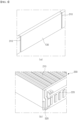
- FIG. 3 is an enlarged view of the structure of the guide structure 300 interposed between the battery cell assembly 200 and the single crossbeam 130, separately illustrating the guide structure 300 provided in the battery cell assembly 200 and the single crossbeam 130, respectively.
- each battery cell assembly 200 includes a plurality of battery cells 210 and a busbar frame assembly 220 that mechanically and electrically couples to the plurality of battery cells 210 at transverse ends from which leads 212 of the battery cells 210 protrude.
- the guide structure 300 on the side of the battery cell assembly 200 is a protruding guide rib 320, which is provided, for example, on the side of the busbar frame assembly 220.
- the guide structure 300 on the side of the single crossbeam 130 is provided with guide slots 310 recessed along the height direction (the z-axis direction in the drawing).
- a secondary battery having a plurality of positive and negative electrodes, a separator laminated therebetween, and leads 212 electrically connecting each of the electrode taps provided on the positive and negative electrodes is referred to herein as a battery cell 210, i.e., a battery cell 210 refers to a single, completed battery cell capable of being repeatedly charged and discharged, and is not limited to the form of a pouch cell, prismatic cell, or the like.
- the battery cell assembly 200 corresponds to the concept of a module of a plurality of such battery cells 210, wherein a batch of battery cells 210 are mechanically constrained and electrically connected by a busbar frame assembly 220 at the front and rear ends.
- FIG. 4 is a diagram illustrating a structure in which a battery cell assembly 200 couples to a single crossbeam 130 through a guide structure 300.
- the cell assembly 200 is mounted in the pack case 100 with both sides facing the single cross beam 130, i.e., with the busbar frame assemblies 220 at the front and rear ends facing longitudinally (Y direction in the drawing).
- the distance between the parallel single crossbeams 130 corresponds to the full width of the battery cell assembly 200. Accordingly, in order to insert the battery cell assembly 200 between the paired single crossbeams 130, mounting can only be accomplished by aligning the guide ribs 320 of the battery cell assembly 200 with the guide slots 310 of the single crossbeams 130.
- the mounting position of each battery cell assembly 200 with respect to the base plate 110 is precisely regulated.
- the battery cell assembly 200 is regulated in its movement in the XY plane formed by the base plate 110.
- the battery cell assembly 200 can only move in the insertion direction and cannot move on the base plate 110.
- the mounting position of each battery cell assembly 200 on the base plate 110 is rigidly fixed by the guide structure 300.
- guide structures 300 may be provided at four corners of the battery cell assembly 200. Further, guide slots 310 may be formed across the entire height of the single crossbeam 130, while guide ribs 320 may be formed along the sides of the busbar frame assembly 220 for at least a portion of the entire height. By forming the guide ribs 320 over a portion of the height of the busbar frame assembly 220, good accessibility to the terminals 222 provided on the busbar frame assembly 220 can be provided. In this case, the guide ribs 320 preferably extend from the bottom of the busbar frame assembly 220, as this is advantageous for determining an initial insertion position for the guide slots 310 of the single crossbeam 130.
- a second embodiment describes an embodiment for a fixing structure 400 that can constrain the battery cell assembly 200 in the Z-axis direction.
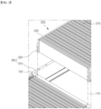
- FIG. 5 is a diagram illustrating the structure of the fixing structure 400 interposed between the battery cell assembly 200 and the single cross beam 130
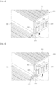
- FIG. 6 is a diagram illustrating the fixing structure 400 provided on the battery cell assembly 200
- FIG. 7 is a diagram illustrating the fixing structure 400 provided on the single cross beam 130.
- the fixing structure 400 includes a first groove 410 recessed in a lower part of the single crossbeam 130, and a first hook 412 provided in the busbar frame assembly 220 to engage the first groove 410.
- the first hook 412 is a resiliently movable resilient hook, and the first groove 410 and the first hook 412 form a snap-fit joint 414. That is, when the guide ribs 320 of the battery cell assembly 200 are snapped into the guide slots 310 on the pair of single crossbeams 130, the first hook 412, which is a cantilevered resilient hook, slides over the surface of the single crossbeam 130 in a slightly retracted position. Once the first hook 412 is aligned with the first groove 410, it resiliently returns to its original position, forming a snap-fit joint 414 in which the wedge end of the first hook 412 engages the upper end of the first groove 410.
- FIG. 8 is a rear view of the structure of the fixture 400 of FIG. 5
- FIG. 10 is a cross-sectional view of portion "A" of FIG. 8 .
- the battery cell assembly 200 is constrained from movement in the (+)Z-axis direction by the snap-fit action of the first hook 412 engaging the upper end of the first groove 410.
- the battery cell assembly 200 mounted within the single crossbeam 130 is prevented from deviating upwardly.
- the fixing structure 400 may further include a second groove 420 recessed in an upper part of the single cross beam 130, and a second hook 422 provided in the busbar frame assembly 220 to contact a step of the second groove 420.
- the second groove 420 is an open groove with an open top
- the second hook 422 is configured as a rigid hook that contacts the lower end of the second groove 420 to support the battery cell assembly 200.
- FIG. 9 is a top view of the structure of the anchoring structure 400 of FIG. 5
- FIG. 11 is a cross-sectional view of portion "B" of FIG. 8 , wherein the inner surface of the wedge end of the second hook 422 is configured to hook the lower step of the second groove 420, such that the cell assembly 200 is no longer able to move downwardly, i.e., in the (-)Z-axis direction.
- the battery cell assembly 200 is prevented from being pressed against the base plate 110 even if downward pressure is applied to the battery cell assembly 200.
- the second hook 422 and second groove 420 are useful to prevent the lower part of the battery cell assembly 200 from being damaged by external forces, as there is no framing structure to protect the lower surface of the battery cell assembly 200.
- the second groove 420 is configured as an upwardly opening groove and the second hook 422 as a rigid hook because it is more advantageous to enhance the downward protection of such a battery cell assembly 200, but the second hook 422 and second groove 420 could also be configured as a snap-fit joint if movement in the (-)Z-axis direction can be limited.
- first groove 410 and the second groove 420 may be separately disposed from each other in and around the guide slot 310.
- the separate arrangement of the first groove 410 and the second groove 420 entails a corresponding separate arrangement of the first hook 412 and the second hook 422.
- This separate arrangement of the fixing structure 400 allows for a more stable positioning of the battery cell assembly 200 by distributing the point of action of the force about the z-axis direction, as well as avoiding interference with the binding action of the first hook 412 and the second hook 422 on each of the first hook 412 and the second hook 422.
- the first hook 412 may be disposed further out on the periphery of the battery cell assembly 200 than the second hook 422. This is because it is more stable for the first hook 412, which is a deformable resilient hook, to constrain the battery cell assembly 200 over as large an area as possible.
- the first hook 412 and second hook 422, along with the guide ribs 320, may be disposed on the sides of the busbar frame assembly 220.
Landscapes
- Chemical & Material Sciences (AREA)
- Chemical Kinetics & Catalysis (AREA)
- Electrochemistry (AREA)
- General Chemical & Material Sciences (AREA)
- Battery Mounting, Suspending (AREA)
- Connection Of Batteries Or Terminals (AREA)
Abstract
Description
- The present invention relates to a battery pack, and more particularly to a battery pack in which a single cross beam can improve the structural stiffness and space utilization of the pack case, facilitate the in-pack mounting of a battery cell assembly, and ensure its solid fixed state.
- This application claims the benefit of priority based on
Korean Patent Application No. 10-2022-0167141, filed on December 02, 2022 Korean Patent Application No. 10-2023-0036409, filed on March 21, 2023 - Cell-to-pack battery packs have been proposed to improve the space utilization of battery packs. The cell-to-pack structure has the advantage of improving the space utilization of the battery pack by assembling a plurality of cells directly into the battery pack without modularization.
- As separate module housings are omitted or simplified in cell-to-pack structures, it becomes important to ensure the stiffness of the battery pack. For example, a plurality of cells forming a battery cell assembly (corresponding to a conventional battery module) can be coupled to a side frame, and the side frame of the battery cell assembly housed in the pack case can be designed to act as the crossbeam of a conventional battery pack.
- However, when a plurality of cell assemblies are arranged in the width direction of the pack case to increase the capacity of the battery pack, the side frames of adjacent cell assemblies facing each other in the width direction center of the battery pack are not connected to each other, which weakens the structural stiffness of the battery pack.
- To solve this problem, a structure can be designed in which a center beam is placed at the length direction center of the battery pack, and the side frames that are not connected to each other are connected and fixed to the center beam. However, this combination of side frames and center beams complicates the assembly process of the battery pack, increases the weight of the battery pack as the number of parts increases, and reduces the energy density of the battery pack by reducing the space utilization as previously.
- In constructing a battery pack with a cell-to-pack structure, the present invention is directed to providing a battery pack that is capable of maintaining good stiffness even in a simplified structure, simplifies the process of mounting a plurality of cell assemblies, and allows for solid regulation of the position of the cell assemblies.
- However, the technical problem to be solved by the present invention is not limited to the above-described problem, and other problems not mentioned can be clearly understood by a person skilled in the art from the description of the invention described below.
- The present invention relates to a battery pack, comprising, in one example, a base plate, side plates coupled along a periphery of the base plate to form a receiving space therein, and a single crossbeam coupled to the base plate to transversely and integrally divide the receiving space inside the base plate, and a plurality of cell assemblies mounted in the receiving space divided by the single crossbeam, and interposed between the plurality of battery cell assemblies and the single crossbeam is a guide structure regulating the position of each battery cell assembly in an XY plane corresponding to a surface of the base plate.
- In one embodiment, the battery cell assembly may comprise a plurality of battery cells and a busbar frame assembly mechanically and electrically coupling to the plurality of battery cells at transverse ends wherein leads of the battery cells protrude, and the guide structure may comprise guide slots recessed and formed along a height direction of the single crossbeam, and guide ribs provided in the busbar frame assembly to glide along the guide slots.
- The guide structures may be provided at four corners of the battery cell assembly.
- Further, the guide slots may be formed over the entire height of the single crossbeam, and the guide ribs may be formed over at least a portion of the entire height along the sides of the busbar frame assembly.
- Meanwhile, the battery pack of the present invention may be interposed between the plurality of battery cell assemblies and the single cross beam, a fixing structure regulating the position of each battery cell assembly along the Z-axis.
- The fixing structure may be a first groove recessed and formed in a lower part of the single crossbeam, and a first hook provided in the busbar frame assembly to engage the first groove.
- In one embodiment, this first hook may be a resiliently movable resilient hook, and this first groove and first hook may form a snap-fit joint.
- Additionally, the fixing structure may further comprise a second groove recessed and formed in an upper part of the single cross beam, and a second hook provided in the busbar frame assembly to contact a lower step of the second groove.
- In one embodiment, the second groove may be an open groove with an open top, and the second hook may be a rigid hook for contacting a lower step of the second groove to support the battery cell assembly.
- Further, the first groove and the second groove may be disposed separately from each other, in and around the boundary of the guide slot.
- For example, the first hook may be disposed further outwardly of the battery cell assembly than the second hook.
- The first hook and the second hook, together with the guide ribs, may be disposed on the sides of the busbar frame assembly.
- In the battery pack of the present invention having the above structure, the receiving space inside the pack case is divided by a single cross beam, and the single cross beam is connected as one across the entire transverse direction of the pack case. Thus, the absence of a center beam simplifies the assembly process of the battery pack, reduces the number of parts, enables the battery pack to be lightweight, improves space utilization, and maintains good stiffness of the pack case by the single cross beam.
- In addition, the installation position of the plurality of cell assemblies is regulated precisely when the plurality of cell assemblies are mounted between the paired single crossbeams by guide structures and fixing structures interposed between the plurality of cell assemblies and the single crossbeam.
- However, the technical effects that can be obtained through the present invention is not limited to the above-described effects, and other effects not mentioned can be clearly understood by a person skilled in the art from the description of the invention described below.
- Because the following drawings attached to the present specification illustrate exemplary embodiments of the present invention and serve to facilitate understanding of the technical idea of the present invention together with the detailed description of the invention described below, the present invention should not be limitedly interpreted on the basis of the drawings.
-
FIG. 1 is an overall view of the internal structure of a battery pack according to one embodiment of the present invention. -
FIG. 2 is a drawing illustrating a structure in which a battery cell assembly is mounted in a pack case. -
FIG. 3 is an enlarged view of the structure of a guide structure interposed between the battery cell assembly and a single cross beam. -
FIG. 4 is a diagram illustrating a structure in which the battery cell assembly is coupled to the single crossbeam through the guide structure. -
FIG. 5 is an enlarged view of the structure of the fixing structure interposed between the battery cell assembly and the single cross beam. -
FIG. 6 illustrates a fixing structure provided on the battery cell assembly. -
FIG. 7 illustrates a fixing structure provided on the single cross beam. -
FIG. 8 is a rear view of the structure of the fixing structure ofFIG. 5 . -
FIG. 9 is a top view of the structure of the fixing structure ofFIG. 5 . -
FIG. 10 is a cross-sectional view of the "A" portion ofFIG. 8 . -
FIG. 11 is a cross-sectional view of the "B" portion ofFIG. 8 . - The present invention may have various modifications and various embodiments, and thus specific embodiments thereof will be described in detail below.
- However, it should be understood that the present invention is not limited to the specific embodiments, and includes all modifications, equivalents, or alternatives within the spirit and technical scope of the present invention.
- The terms "comprise," "include," and "have" used herein designate the presence of characteristics, numbers, steps, actions, components, or members described in the specification or a combination thereof, and it should be understood that the possibility of the presence or addition of one or more other characteristics, numbers, steps, actions, components, members, or a combination thereof is not excluded in advance.
- In addition, in the present invention, when a part of a layer, film, region, plate, or the like is disposed "on" another part, this includes not only a case in which one part is disposed "directly on" another part, but a case in which still another part is interposed therebetween. In contrast, when a part of a layer, film, region, plate, or the like is disposed "under" another part, this includes not only a case in which one part is disposed "directly under" another part, but a case in which still another part is interposed therebetween. In addition, in the present application, "on" may include not only a case of being disposed on an upper portion but also a case of being disposed on a lower portion.
- The present invention relates to a battery pack, comprising, in one example, a base plate, side plates coupled along a periphery of the base plate to form a receiving space therein, and a single crossbeam coupled to the base plate to transversely and integrally divide the receiving space inside the base plate, and a plurality of cell assemblies mounted in the receiving space divided by the single crossbeam, wherein between the plurality of cell assemblies and the single crossbeam is interposed a guide structure regulating the position of each battery cell assembly in an XY plane corresponding to a surface of the base plate.
- In the battery pack of the present invention with such a structure, the receiving space inside the pack case is divided by a single cross beam, and the single cross beam is connected as one across the entire transverse direction of the pack case. Thus, the absence of a center beam simplifies the assembly process of the battery pack, reduces the number of parts, enables the battery pack to be lightweight, improves space utilization, and maintains good stiffness of the pack case by the single cross beam.
- In addition, the installation position of the plurality of cell assemblies is regulated precisely when the plurality of cell assemblies are mounted between the paired single crossbeams by guide structures interposed between the plurality of cell assemblies and the single crossbeam.
- Hereinafter, specific embodiments of a secondary battery of the present invention will be described in detail with reference to the accompanying drawings. For reference, the directions of front, back, up, down, left, and right used in the following description to designate relative positions are for the purpose of understanding the invention and refer to the directions shown in the drawings unless otherwise specified.
-
FIG. 1 is an overall view of the internal structure of a battery pack according to one embodiment of the present invention, andFIG. 2 is a drawing illustrating a structure in which a battery cell assembly is mounted in a pack case. Abattery pack 10 of the present invention includes apack case 100 and a plurality ofbattery cell assemblies 200 mounted within thepack case 100. - The
pack case 100 includes abase plate 110,side plates 120 coupled along the perimeter of thebase plate 110 to form a receiving space therein, and asingle cross beam 130 coupled to thebase plate 110 to transversely enclose the receiving space within thebase plate 110. As used herein, thesingle cross beam 130 refers to a cross beam that is uninterrupted across the full width of theside plate 120 in the transverse direction (x-axis direction in the drawings), such that good stiffness against transverse loading is provided by thesingle cross beam 130 without the need for additional separation walls, such as a center beam. - Additionally, a plurality of
battery cell assemblies 200 are mounted in the receiving space transversely divided by thesingle cross beam 130. As shown, there is no longitudinal separation walls such as a center beam, inside thepack case 100 of the present invention, so that space exists betweenadjacent cell assemblies 200. For example, when twocell assemblies 200 are arranged transversely, as in the embodiment shown, there is a free space in the central area of thepack case 100 for electrical wiring and the like. Therefore, there is a need for a means to regulate the position betweencell assemblies 200 that share the same accommodation space, in place of the module housing or center beam provided in theconventional battery pack 10. - For this purpose, the
battery pack 10 of the present invention comprises aguide structure 300 interposed between the plurality ofbattery cell assemblies 200 and thesingle cross beam 130, theguide structure 300 regulating the position of eachbattery cell assembly 200 in an XY plane corresponding to the surface of thebase plate 110. -
FIG. 3 is an enlarged view of the structure of theguide structure 300 interposed between thebattery cell assembly 200 and thesingle crossbeam 130, separately illustrating theguide structure 300 provided in thebattery cell assembly 200 and thesingle crossbeam 130, respectively. - In the embodiment of
FIG. 3 , eachbattery cell assembly 200 includes a plurality ofbattery cells 210 and abusbar frame assembly 220 that mechanically and electrically couples to the plurality ofbattery cells 210 at transverse ends from which leads 212 of thebattery cells 210 protrude. Theguide structure 300 on the side of thebattery cell assembly 200 is a protrudingguide rib 320, which is provided, for example, on the side of thebusbar frame assembly 220. Correspondingly, theguide structure 300 on the side of thesingle crossbeam 130 is provided withguide slots 310 recessed along the height direction (the z-axis direction in the drawing). - For reference, a secondary battery having a plurality of positive and negative electrodes, a separator laminated therebetween, and leads 212 electrically connecting each of the electrode taps provided on the positive and negative electrodes is referred to herein as a
battery cell 210, i.e., abattery cell 210 refers to a single, completed battery cell capable of being repeatedly charged and discharged, and is not limited to the form of a pouch cell, prismatic cell, or the like. Further, thebattery cell assembly 200 corresponds to the concept of a module of a plurality ofsuch battery cells 210, wherein a batch ofbattery cells 210 are mechanically constrained and electrically connected by abusbar frame assembly 220 at the front and rear ends. -
FIG. 4 is a diagram illustrating a structure in which abattery cell assembly 200 couples to asingle crossbeam 130 through aguide structure 300. Thecell assembly 200 is mounted in thepack case 100 with both sides facing thesingle cross beam 130, i.e., with thebusbar frame assemblies 220 at the front and rear ends facing longitudinally (Y direction in the drawing). The distance between the parallelsingle crossbeams 130 corresponds to the full width of thebattery cell assembly 200. Accordingly, in order to insert thebattery cell assembly 200 between the pairedsingle crossbeams 130, mounting can only be accomplished by aligning theguide ribs 320 of thebattery cell assembly 200 with theguide slots 310 of thesingle crossbeams 130. Thus, the mounting position of eachbattery cell assembly 200 with respect to thebase plate 110 is precisely regulated. - Further, with the
guide slots 310 and guideribs 320 formed along the Z-axis direction, thebattery cell assembly 200 is regulated in its movement in the XY plane formed by thebase plate 110. In other words, with theguide structure 300 in the position, thebattery cell assembly 200 can only move in the insertion direction and cannot move on thebase plate 110. Thus, the mounting position of eachbattery cell assembly 200 on thebase plate 110 is rigidly fixed by theguide structure 300. - For accurate and solid positioning of the
battery cell assembly 200, guidestructures 300 may be provided at four corners of thebattery cell assembly 200. Further, guideslots 310 may be formed across the entire height of thesingle crossbeam 130, whileguide ribs 320 may be formed along the sides of thebusbar frame assembly 220 for at least a portion of the entire height. By forming theguide ribs 320 over a portion of the height of thebusbar frame assembly 220, good accessibility to theterminals 222 provided on thebusbar frame assembly 220 can be provided. In this case, theguide ribs 320 preferably extend from the bottom of thebusbar frame assembly 220, as this is advantageous for determining an initial insertion position for theguide slots 310 of thesingle crossbeam 130. - By the
guide structure 300 according to the first embodiment, the position of thebattery cell assembly 200 in the XY plane with respect to thepack case 100 is effectively regulated. In addition, a second embodiment describes an embodiment for a fixingstructure 400 that can constrain thebattery cell assembly 200 in the Z-axis direction. - A fixing
structure 400 for regulating the position of thebattery cell assembly 200 in the Z-axis direction is also provided between thebattery cell assembly 200 and thesingle cross beam 130.FIG. 5 is a diagram illustrating the structure of the fixingstructure 400 interposed between thebattery cell assembly 200 and thesingle cross beam 130,FIG. 6 is a diagram illustrating the fixingstructure 400 provided on thebattery cell assembly 200, andFIG. 7 is a diagram illustrating the fixingstructure 400 provided on thesingle cross beam 130. As shown, the fixingstructure 400 includes afirst groove 410 recessed in a lower part of thesingle crossbeam 130, and afirst hook 412 provided in thebusbar frame assembly 220 to engage thefirst groove 410. - In one embodiment of the present invention, the
first hook 412 is a resiliently movable resilient hook, and thefirst groove 410 and thefirst hook 412 form a snap-fit joint 414. That is, when theguide ribs 320 of thebattery cell assembly 200 are snapped into theguide slots 310 on the pair ofsingle crossbeams 130, thefirst hook 412, which is a cantilevered resilient hook, slides over the surface of thesingle crossbeam 130 in a slightly retracted position. Once thefirst hook 412 is aligned with thefirst groove 410, it resiliently returns to its original position, forming a snap-fit joint 414 in which the wedge end of thefirst hook 412 engages the upper end of thefirst groove 410. -
FIG. 8 is a rear view of the structure of thefixture 400 ofFIG. 5 , andFIG. 10 is a cross-sectional view of portion "A" ofFIG. 8 . As shown, thebattery cell assembly 200 is constrained from movement in the (+)Z-axis direction by the snap-fit action of thefirst hook 412 engaging the upper end of thefirst groove 410. In other words, by thefirst hook 412 and thefirst groove 410, thebattery cell assembly 200 mounted within thesingle crossbeam 130 is prevented from deviating upwardly. - The fixing
structure 400 may further include asecond groove 420 recessed in an upper part of thesingle cross beam 130, and asecond hook 422 provided in thebusbar frame assembly 220 to contact a step of thesecond groove 420. In the embodiment shown, thesecond groove 420 is an open groove with an open top, and thesecond hook 422 is configured as a rigid hook that contacts the lower end of thesecond groove 420 to support thebattery cell assembly 200. - While the
first hook 412 andfirst groove 410 are intended to constrain the (+)Z-axis movement of thebattery cell assembly 200, thesecond hook 422 andsecond groove 420 are intended to constrain the (-)Z-axis movement of thebattery cell assembly 200.FIG. 9 is a top view of the structure of the anchoringstructure 400 ofFIG. 5 , andFIG. 11 is a cross-sectional view of portion "B" ofFIG. 8 , wherein the inner surface of the wedge end of thesecond hook 422 is configured to hook the lower step of thesecond groove 420, such that thecell assembly 200 is no longer able to move downwardly, i.e., in the (-)Z-axis direction. - By the
second hook 422 andsecond groove 420, thebattery cell assembly 200 is prevented from being pressed against thebase plate 110 even if downward pressure is applied to thebattery cell assembly 200. In particular, when thebattery cell assembly 200 is mounted in thepack case 100 as a cell-to-pack structure without a separate module housing, thesecond hook 422 andsecond groove 420 are useful to prevent the lower part of thebattery cell assembly 200 from being damaged by external forces, as there is no framing structure to protect the lower surface of thebattery cell assembly 200. - In the shown embodiment, the
second groove 420 is configured as an upwardly opening groove and thesecond hook 422 as a rigid hook because it is more advantageous to enhance the downward protection of such abattery cell assembly 200, but thesecond hook 422 andsecond groove 420 could also be configured as a snap-fit joint if movement in the (-)Z-axis direction can be limited. - In addition, as in the embodiment shown in
FIGS. 6 to 9 , thefirst groove 410 and thesecond groove 420 may be separately disposed from each other in and around theguide slot 310. The separate arrangement of thefirst groove 410 and thesecond groove 420 entails a corresponding separate arrangement of thefirst hook 412 and thesecond hook 422. This separate arrangement of the fixingstructure 400 allows for a more stable positioning of thebattery cell assembly 200 by distributing the point of action of the force about the z-axis direction, as well as avoiding interference with the binding action of thefirst hook 412 and thesecond hook 422 on each of thefirst hook 412 and thesecond hook 422. - For example, the
first hook 412 may be disposed further out on the periphery of thebattery cell assembly 200 than thesecond hook 422. This is because it is more stable for thefirst hook 412, which is a deformable resilient hook, to constrain thebattery cell assembly 200 over as large an area as possible. Thefirst hook 412 andsecond hook 422, along with theguide ribs 320, may be disposed on the sides of thebusbar frame assembly 220. By disposing theguide structure 300 and the fixingstructure 400 together on the sides of thebusbar frame assembly 220, the structural design of thebusbar frame assembly 220 is simplified, and access to theterminals 222 and various insulation and protection designs are improved. - As above, the present invention has been described in more detail through the drawings and embodiments. However, since the configuration described in the drawings or embodiments described herein is merely one embodiment of the present invention and do not represent the overall technical spirit of the invention, it should be understood that the invention covers various equivalents, modifications, and substitutions at the time of filing of this application.
-
- 10: battery pack
- 100: pack case
- 110: base plate
- 120: side plate
- 130: single cross beam
- 200: battery cell assembly
- 210: battery cell
- 220: busbar frame assembly
- 222: terminal
- 300: guide structure
- 310: guide slot
- 320: guide rib
- 400: fixing structure
- 410: first groove
- 412: first hook
- 414: snap-fit joint
- 420: second groove
- 422: second hook
Claims (12)
- A battery pack, comprising:a base plate;side plates coupled to one another and to the base plate along a periphery of the base plate to form a receiving space therein; anda crossbeam coupled to the base plate that transversely divides the receiving space inside the base plate; anda plurality of battery cell assemblies mounted in the receiving space,wherein the plurality of battery cell assemblies and the crossbeam together comprise a guide structure fixing a position of each cell assembly in an XY plane relative to a surface of the base plate.
- The battery pack of claim 1, wherein each battery cell assembly comprises a plurality of battery cells and a busbar frame assembly mechanically and electrically coupling to the plurality of battery cells at transverse ends thereof where leads of the battery cells protrude, and
the guide structure comprises guide slots recessed into and extending along a height direction of the crossbeam and guide ribs extending from each busbar frame assembly, the guide ribs configured to glide along the guide slots during insertion of the battery cell assemblies into the receiving space. - The battery pack of claim 2, wherein the crossbeam is a first crossbeam and the guide structure is a first guide structure of a plurality of guide structures, the battery pack further comprising a second crossbeam, each of the first and second crossbeams comprising portions of a plurality of guide structures, one of the guide structures being located at each of four corners of the battery cell assembly, respectively.
- The battery pack of claim 2, wherein the guide slots extend along an entire height of the crossbeam, and the guide ribs extend along at least a portion of an entire height of the sides of each busbar frame assembly.
- The battery pack of claim 2, wherein the plurality of battery cell assemblies and the crossbeam together comprise a fixing structure fixing a position of each battery cell assembly relative to the base plate along a Z-axis of the battery pack.
- The battery pack of claim 5, wherein the fixing structure includes a first groove recessed into a lower part of the crossbeam and a first hook extending from each busbar frame assembly, the first hook engaged with the first groove.
- The battery pack of claim 6, wherein the first hook is a resiliently movable resilient hook, and the first groove and first hook together form a snap-fit joint.
- The battery pack of claim 6, wherein the fixing structure further comprises a second groove recessed into an upper part of the crossbeam and a second hook extending from each busbar frame assembly and contacting a lower step of the second groove.
- The battery pack of claim 8, wherein the second groove has an open top, and the second hook is a rigid hook that contacts the lower step of the second groove to support the battery cell assembly.
- The battery pack of claim 8, wherein the first groove and the second groove are spaced apart from each other and are each disposed outside of an outer boundary of the guide slot.
- The battery pack of claim 10, wherein the first hook is extends further away from the battery cell assembly than the second hook.
- The battery pack of claim 8, wherein the first hook, the second hook, and the guide ribs are each disposed on sides of the busbar frame assembly.
Applications Claiming Priority (3)
| Application Number | Priority Date | Filing Date | Title |
|---|---|---|---|
| KR20220167141 | 2022-12-02 | ||
| KR1020230036409A KR20240082983A (en) | 2022-12-02 | 2023-03-21 | Battery pack |
| PCT/KR2023/019148 WO2024117692A1 (en) | 2022-12-02 | 2023-11-24 | Battery pack |
Publications (2)
| Publication Number | Publication Date |
|---|---|
| EP4471957A1 true EP4471957A1 (en) | 2024-12-04 |
| EP4471957A4 EP4471957A4 (en) | 2025-05-21 |
Family
ID=91324508
Family Applications (1)
| Application Number | Title | Priority Date | Filing Date |
|---|---|---|---|
| EP23898223.5A Pending EP4471957A4 (en) | 2022-12-02 | 2023-11-24 | BATTERY PACK |
Country Status (4)
| Country | Link |
|---|---|
| US (1) | US20250174804A1 (en) |
| EP (1) | EP4471957A4 (en) |
| JP (1) | JP7782056B2 (en) |
| WO (1) | WO2024117692A1 (en) |
Cited By (1)
| Publication number | Priority date | Publication date | Assignee | Title |
|---|---|---|---|---|
| DE102025103450B3 (en) * | 2025-01-30 | 2026-02-05 | Dr. Ing. H.C. F. Porsche Aktiengesellschaft | Method for manufacturing a battery for a motor vehicle |
Family Cites Families (10)
| Publication number | Priority date | Publication date | Assignee | Title |
|---|---|---|---|---|
| KR102162968B1 (en) * | 2017-04-07 | 2020-10-07 | 주식회사 엘지화학 | Battery Pack with extendible battery module |
| KR102152347B1 (en) * | 2017-06-22 | 2020-09-04 | 주식회사 엘지화학 | Battery pack |
| CN112310541B (en) * | 2019-11-19 | 2022-03-29 | 宁德时代新能源科技股份有限公司 | Battery pack and vehicle |
| KR102802106B1 (en) * | 2020-07-28 | 2025-05-02 | 에스케이온 주식회사 | Battery pack |
| CN114843712A (en) * | 2021-02-01 | 2022-08-02 | 恒大新能源技术(深圳)有限公司 | Battery modules and battery packs |
| KR20220156319A (en) * | 2021-05-18 | 2022-11-25 | 남도금형(주) | Battery case for electric vehicle |
| KR102581241B1 (en) | 2021-06-11 | 2023-09-22 | 한국원자력연구원 | Habitability and dose assessment system and operating method of the same |
| CN215578820U (en) * | 2021-06-23 | 2022-01-18 | 上海卡耐新能源有限公司 | Battery package box structure and battery package |
| CN215451614U (en) * | 2021-06-29 | 2022-01-07 | 比亚迪股份有限公司 | Battery box and battery package |
| KR20230036409A (en) | 2021-09-07 | 2023-03-14 | 삼성전자주식회사 | Electronic device for sharpening an image and operating method for the same |
-
2023
- 2023-11-24 JP JP2024545198A patent/JP7782056B2/en active Active
- 2023-11-24 WO PCT/KR2023/019148 patent/WO2024117692A1/en not_active Ceased
- 2023-11-24 EP EP23898223.5A patent/EP4471957A4/en active Pending
- 2023-11-24 US US18/842,611 patent/US20250174804A1/en active Pending
Cited By (1)
| Publication number | Priority date | Publication date | Assignee | Title |
|---|---|---|---|---|
| DE102025103450B3 (en) * | 2025-01-30 | 2026-02-05 | Dr. Ing. H.C. F. Porsche Aktiengesellschaft | Method for manufacturing a battery for a motor vehicle |
Also Published As
| Publication number | Publication date |
|---|---|
| JP2025503289A (en) | 2025-01-30 |
| US20250174804A1 (en) | 2025-05-29 |
| EP4471957A4 (en) | 2025-05-21 |
| WO2024117692A1 (en) | 2024-06-06 |
| JP7782056B2 (en) | 2025-12-08 |
Similar Documents
| Publication | Publication Date | Title |
|---|---|---|
| US11264670B2 (en) | Battery pack having expandable battery module structure | |
| US12283708B2 (en) | Terminal protection device and battery module | |
| KR20220065548A (en) | Battery Module and Battery Pack Having the same | |
| EP4407770B1 (en) | Battery pack | |
| US11289775B2 (en) | Battery wiring module including elastic joiners | |
| EP3940867B1 (en) | Battery pack with enhanced structure for preventing short circuit and shock | |
| EP4318764B1 (en) | Battery pack and vehicle including the same | |
| US20250174804A1 (en) | Battery Pack | |
| EP3846280A1 (en) | Battery pack | |
| WO2023239158A1 (en) | Battery pack and vehicle including same | |
| KR102805410B1 (en) | Battery module having brackets that can adjust the width, and a battery pack comprising the same, and a vehicle including such a battery pack | |
| EP4465430A1 (en) | Battery block | |
| KR20240123765A (en) | Battery pack | |
| EP4266465A1 (en) | Battery module | |
| EP4131608A1 (en) | Battery pack | |
| CN118696453A (en) | Battery Pack | |
| KR20240021694A (en) | Battery pack and vehicle including the same | |
| KR20230170563A (en) | Battery pack and vehicle including the same | |
| KR20240082983A (en) | Battery pack | |
| EP4675802A1 (en) | Battery module and battery pack and vehicle including same | |
| EP4654356A1 (en) | Connector assembly | |
| EP4510339A1 (en) | Cell stack assembly and battery pack comprising cell stack assembly | |
| KR20250158416A (en) | Battery pack | |
| KR20240117359A (en) | Battery pack and Battery pack frame | |
| KR20230174035A (en) | Battery cell fixing apparatus |
Legal Events
| Date | Code | Title | Description |
|---|---|---|---|
| STAA | Information on the status of an ep patent application or granted ep patent |
Free format text: STATUS: THE INTERNATIONAL PUBLICATION HAS BEEN MADE |
|
| PUAI | Public reference made under article 153(3) epc to a published international application that has entered the european phase |
Free format text: ORIGINAL CODE: 0009012 |
|
| STAA | Information on the status of an ep patent application or granted ep patent |
Free format text: STATUS: REQUEST FOR EXAMINATION WAS MADE |
|
| 17P | Request for examination filed |
Effective date: 20240827 |
|
| AK | Designated contracting states |
Kind code of ref document: A1 Designated state(s): AL AT BE BG CH CY CZ DE DK EE ES FI FR GB GR HR HU IE IS IT LI LT LU LV MC ME MK MT NL NO PL PT RO RS SE SI SK SM TR |
|
| A4 | Supplementary search report drawn up and despatched |
Effective date: 20250417 |
|
| RIC1 | Information provided on ipc code assigned before grant |
Ipc: H01M 50/204 20210101ALI20250411BHEP Ipc: H01M 50/258 20210101ALI20250411BHEP Ipc: H01M 50/207 20210101ALI20250411BHEP Ipc: H01M 50/262 20210101ALI20250411BHEP Ipc: H01M 50/291 20210101AFI20250411BHEP |
|
| GRAP | Despatch of communication of intention to grant a patent |
Free format text: ORIGINAL CODE: EPIDOSNIGR1 |
|
| STAA | Information on the status of an ep patent application or granted ep patent |
Free format text: STATUS: GRANT OF PATENT IS INTENDED |
|
| INTG | Intention to grant announced |
Effective date: 20260130 |
|
| DAV | Request for validation of the european patent (deleted) | ||
| DAX | Request for extension of the european patent (deleted) | ||
| P01 | Opt-out of the competence of the unified patent court (upc) registered |
Free format text: CASE NUMBER: UPC_APP_0003965_4471957/2026 Effective date: 20260203 |