EP4471939A1 - Battery pack and electric equipment - Google Patents
Battery pack and electric equipment Download PDFInfo
- Publication number
- EP4471939A1 EP4471939A1 EP24174464.8A EP24174464A EP4471939A1 EP 4471939 A1 EP4471939 A1 EP 4471939A1 EP 24174464 A EP24174464 A EP 24174464A EP 4471939 A1 EP4471939 A1 EP 4471939A1
- Authority
- EP
- European Patent Office
- Prior art keywords
- battery
- reinforcement
- battery pack
- liquid cooling
- beams
- Prior art date
- Legal status (The legal status is an assumption and is not a legal conclusion. Google has not performed a legal analysis and makes no representation as to the accuracy of the status listed.)
- Pending
Links
- 230000002787 reinforcement Effects 0.000 claims abstract description 89
- 238000001816 cooling Methods 0.000 claims abstract description 70
- 239000007788 liquid Substances 0.000 claims abstract description 69
- 238000009434 installation Methods 0.000 claims description 48
- 238000003466 welding Methods 0.000 claims description 14
- 230000002093 peripheral effect Effects 0.000 claims description 10
- 229920001821 foam rubber Polymers 0.000 claims description 6
- WYTGDNHDOZPMIW-RCBQFDQVSA-N alstonine Natural products C1=CC2=C3C=CC=CC3=NC2=C2N1C[C@H]1[C@H](C)OC=C(C(=O)OC)[C@H]1C2 WYTGDNHDOZPMIW-RCBQFDQVSA-N 0.000 claims description 5
- 230000004308 accommodation Effects 0.000 description 5
- 239000000084 colloidal system Substances 0.000 description 3
- 230000000694 effects Effects 0.000 description 3
- 238000004880 explosion Methods 0.000 description 2
- 238000001125 extrusion Methods 0.000 description 2
- 238000009413 insulation Methods 0.000 description 2
- 238000004519 manufacturing process Methods 0.000 description 2
- 239000000463 material Substances 0.000 description 2
- 238000000034 method Methods 0.000 description 2
- 230000009286 beneficial effect Effects 0.000 description 1
- 230000005540 biological transmission Effects 0.000 description 1
- 230000003139 buffering effect Effects 0.000 description 1
- 239000008358 core component Substances 0.000 description 1
- 238000009826 distribution Methods 0.000 description 1
- 239000003292 glue Substances 0.000 description 1
- 230000017525 heat dissipation Effects 0.000 description 1
- 239000002184 metal Substances 0.000 description 1
- 238000013021 overheating Methods 0.000 description 1
- 239000004033 plastic Substances 0.000 description 1
- 230000001681 protective effect Effects 0.000 description 1
- 230000003014 reinforcing effect Effects 0.000 description 1
Images



Classifications
-
- H—ELECTRICITY
- H01—ELECTRIC ELEMENTS
- H01M—PROCESSES OR MEANS, e.g. BATTERIES, FOR THE DIRECT CONVERSION OF CHEMICAL ENERGY INTO ELECTRICAL ENERGY
- H01M50/00—Constructional details or processes of manufacture of the non-active parts of electrochemical cells other than fuel cells, e.g. hybrid cells
- H01M50/20—Mountings; Secondary casings or frames; Racks, modules or packs; Suspension devices; Shock absorbers; Transport or carrying devices; Holders
- H01M50/204—Racks, modules or packs for multiple batteries or multiple cells
- H01M50/207—Racks, modules or packs for multiple batteries or multiple cells characterised by their shape
- H01M50/213—Racks, modules or packs for multiple batteries or multiple cells characterised by their shape adapted for cells having curved cross-section, e.g. round or elliptic
-
- H—ELECTRICITY
- H01—ELECTRIC ELEMENTS
- H01M—PROCESSES OR MEANS, e.g. BATTERIES, FOR THE DIRECT CONVERSION OF CHEMICAL ENERGY INTO ELECTRICAL ENERGY
- H01M10/00—Secondary cells; Manufacture thereof
- H01M10/60—Heating or cooling; Temperature control
- H01M10/61—Types of temperature control
- H01M10/613—Cooling or keeping cold
-
- H—ELECTRICITY
- H01—ELECTRIC ELEMENTS
- H01M—PROCESSES OR MEANS, e.g. BATTERIES, FOR THE DIRECT CONVERSION OF CHEMICAL ENERGY INTO ELECTRICAL ENERGY
- H01M10/00—Secondary cells; Manufacture thereof
- H01M10/60—Heating or cooling; Temperature control
- H01M10/62—Heating or cooling; Temperature control specially adapted for specific applications
- H01M10/625—Vehicles
-
- H—ELECTRICITY
- H01—ELECTRIC ELEMENTS
- H01M—PROCESSES OR MEANS, e.g. BATTERIES, FOR THE DIRECT CONVERSION OF CHEMICAL ENERGY INTO ELECTRICAL ENERGY
- H01M10/00—Secondary cells; Manufacture thereof
- H01M10/60—Heating or cooling; Temperature control
- H01M10/65—Means for temperature control structurally associated with the cells
- H01M10/655—Solid structures for heat exchange or heat conduction
- H01M10/6554—Rods or plates
- H01M10/6555—Rods or plates arranged between the cells
-
- H—ELECTRICITY
- H01—ELECTRIC ELEMENTS
- H01M—PROCESSES OR MEANS, e.g. BATTERIES, FOR THE DIRECT CONVERSION OF CHEMICAL ENERGY INTO ELECTRICAL ENERGY
- H01M10/00—Secondary cells; Manufacture thereof
- H01M10/60—Heating or cooling; Temperature control
- H01M10/65—Means for temperature control structurally associated with the cells
- H01M10/655—Solid structures for heat exchange or heat conduction
- H01M10/6556—Solid parts with flow channel passages or pipes for heat exchange
-
- H—ELECTRICITY
- H01—ELECTRIC ELEMENTS
- H01M—PROCESSES OR MEANS, e.g. BATTERIES, FOR THE DIRECT CONVERSION OF CHEMICAL ENERGY INTO ELECTRICAL ENERGY
- H01M10/00—Secondary cells; Manufacture thereof
- H01M10/60—Heating or cooling; Temperature control
- H01M10/65—Means for temperature control structurally associated with the cells
- H01M10/655—Solid structures for heat exchange or heat conduction
- H01M10/6556—Solid parts with flow channel passages or pipes for heat exchange
- H01M10/6557—Solid parts with flow channel passages or pipes for heat exchange arranged between the cells
-
- H—ELECTRICITY
- H01—ELECTRIC ELEMENTS
- H01M—PROCESSES OR MEANS, e.g. BATTERIES, FOR THE DIRECT CONVERSION OF CHEMICAL ENERGY INTO ELECTRICAL ENERGY
- H01M10/00—Secondary cells; Manufacture thereof
- H01M10/60—Heating or cooling; Temperature control
- H01M10/65—Means for temperature control structurally associated with the cells
- H01M10/656—Means for temperature control structurally associated with the cells characterised by the type of heat-exchange fluid
- H01M10/6567—Liquids
-
- H—ELECTRICITY
- H01—ELECTRIC ELEMENTS
- H01M—PROCESSES OR MEANS, e.g. BATTERIES, FOR THE DIRECT CONVERSION OF CHEMICAL ENERGY INTO ELECTRICAL ENERGY
- H01M10/00—Secondary cells; Manufacture thereof
- H01M10/60—Heating or cooling; Temperature control
- H01M10/65—Means for temperature control structurally associated with the cells
- H01M10/656—Means for temperature control structurally associated with the cells characterised by the type of heat-exchange fluid
- H01M10/6567—Liquids
- H01M10/6568—Liquids characterised by flow circuits, e.g. loops, located externally to the cells or cell casings
-
- H—ELECTRICITY
- H01—ELECTRIC ELEMENTS
- H01M—PROCESSES OR MEANS, e.g. BATTERIES, FOR THE DIRECT CONVERSION OF CHEMICAL ENERGY INTO ELECTRICAL ENERGY
- H01M50/00—Constructional details or processes of manufacture of the non-active parts of electrochemical cells other than fuel cells, e.g. hybrid cells
- H01M50/20—Mountings; Secondary casings or frames; Racks, modules or packs; Suspension devices; Shock absorbers; Transport or carrying devices; Holders
- H01M50/204—Racks, modules or packs for multiple batteries or multiple cells
-
- H—ELECTRICITY
- H01—ELECTRIC ELEMENTS
- H01M—PROCESSES OR MEANS, e.g. BATTERIES, FOR THE DIRECT CONVERSION OF CHEMICAL ENERGY INTO ELECTRICAL ENERGY
- H01M50/00—Constructional details or processes of manufacture of the non-active parts of electrochemical cells other than fuel cells, e.g. hybrid cells
- H01M50/20—Mountings; Secondary casings or frames; Racks, modules or packs; Suspension devices; Shock absorbers; Transport or carrying devices; Holders
- H01M50/233—Mountings; Secondary casings or frames; Racks, modules or packs; Suspension devices; Shock absorbers; Transport or carrying devices; Holders characterised by physical properties of casings or racks, e.g. dimensions
- H01M50/24—Mountings; Secondary casings or frames; Racks, modules or packs; Suspension devices; Shock absorbers; Transport or carrying devices; Holders characterised by physical properties of casings or racks, e.g. dimensions adapted for protecting batteries from their environment, e.g. from corrosion
-
- H—ELECTRICITY
- H01—ELECTRIC ELEMENTS
- H01M—PROCESSES OR MEANS, e.g. BATTERIES, FOR THE DIRECT CONVERSION OF CHEMICAL ENERGY INTO ELECTRICAL ENERGY
- H01M50/00—Constructional details or processes of manufacture of the non-active parts of electrochemical cells other than fuel cells, e.g. hybrid cells
- H01M50/20—Mountings; Secondary casings or frames; Racks, modules or packs; Suspension devices; Shock absorbers; Transport or carrying devices; Holders
- H01M50/233—Mountings; Secondary casings or frames; Racks, modules or packs; Suspension devices; Shock absorbers; Transport or carrying devices; Holders characterised by physical properties of casings or racks, e.g. dimensions
- H01M50/242—Mountings; Secondary casings or frames; Racks, modules or packs; Suspension devices; Shock absorbers; Transport or carrying devices; Holders characterised by physical properties of casings or racks, e.g. dimensions adapted for protecting batteries against vibrations, collision impact or swelling
-
- H—ELECTRICITY
- H01—ELECTRIC ELEMENTS
- H01M—PROCESSES OR MEANS, e.g. BATTERIES, FOR THE DIRECT CONVERSION OF CHEMICAL ENERGY INTO ELECTRICAL ENERGY
- H01M50/00—Constructional details or processes of manufacture of the non-active parts of electrochemical cells other than fuel cells, e.g. hybrid cells
- H01M50/20—Mountings; Secondary casings or frames; Racks, modules or packs; Suspension devices; Shock absorbers; Transport or carrying devices; Holders
- H01M50/244—Secondary casings; Racks; Suspension devices; Carrying devices; Holders characterised by their mounting method
-
- H—ELECTRICITY
- H01—ELECTRIC ELEMENTS
- H01M—PROCESSES OR MEANS, e.g. BATTERIES, FOR THE DIRECT CONVERSION OF CHEMICAL ENERGY INTO ELECTRICAL ENERGY
- H01M50/00—Constructional details or processes of manufacture of the non-active parts of electrochemical cells other than fuel cells, e.g. hybrid cells
- H01M50/20—Mountings; Secondary casings or frames; Racks, modules or packs; Suspension devices; Shock absorbers; Transport or carrying devices; Holders
- H01M50/289—Mountings; Secondary casings or frames; Racks, modules or packs; Suspension devices; Shock absorbers; Transport or carrying devices; Holders characterised by spacing elements or positioning means within frames, racks or packs
-
- H—ELECTRICITY
- H01—ELECTRIC ELEMENTS
- H01M—PROCESSES OR MEANS, e.g. BATTERIES, FOR THE DIRECT CONVERSION OF CHEMICAL ENERGY INTO ELECTRICAL ENERGY
- H01M50/00—Constructional details or processes of manufacture of the non-active parts of electrochemical cells other than fuel cells, e.g. hybrid cells
- H01M50/20—Mountings; Secondary casings or frames; Racks, modules or packs; Suspension devices; Shock absorbers; Transport or carrying devices; Holders
- H01M50/289—Mountings; Secondary casings or frames; Racks, modules or packs; Suspension devices; Shock absorbers; Transport or carrying devices; Holders characterised by spacing elements or positioning means within frames, racks or packs
- H01M50/291—Mountings; Secondary casings or frames; Racks, modules or packs; Suspension devices; Shock absorbers; Transport or carrying devices; Holders characterised by spacing elements or positioning means within frames, racks or packs characterised by their shape
-
- H—ELECTRICITY
- H01—ELECTRIC ELEMENTS
- H01M—PROCESSES OR MEANS, e.g. BATTERIES, FOR THE DIRECT CONVERSION OF CHEMICAL ENERGY INTO ELECTRICAL ENERGY
- H01M50/00—Constructional details or processes of manufacture of the non-active parts of electrochemical cells other than fuel cells, e.g. hybrid cells
- H01M50/50—Current conducting connections for cells or batteries
- H01M50/502—Interconnectors for connecting terminals of adjacent batteries; Interconnectors for connecting cells outside a battery casing
- H01M50/507—Interconnectors for connecting terminals of adjacent batteries; Interconnectors for connecting cells outside a battery casing comprising an arrangement of two or more busbars within a container structure, e.g. busbar modules
-
- Y—GENERAL TAGGING OF NEW TECHNOLOGICAL DEVELOPMENTS; GENERAL TAGGING OF CROSS-SECTIONAL TECHNOLOGIES SPANNING OVER SEVERAL SECTIONS OF THE IPC; TECHNICAL SUBJECTS COVERED BY FORMER USPC CROSS-REFERENCE ART COLLECTIONS [XRACs] AND DIGESTS
- Y02—TECHNOLOGIES OR APPLICATIONS FOR MITIGATION OR ADAPTATION AGAINST CLIMATE CHANGE
- Y02E—REDUCTION OF GREENHOUSE GAS [GHG] EMISSIONS, RELATED TO ENERGY GENERATION, TRANSMISSION OR DISTRIBUTION
- Y02E60/00—Enabling technologies; Technologies with a potential or indirect contribution to GHG emissions mitigation
- Y02E60/10—Energy storage using batteries
Definitions
- the present disclosure relates to the technical field of batteries, and in particular, to a battery pack and an electric equipment.
- a power battery is the energy hub of the electric vehicle.
- a battery pack as an energy distribution unit of the power battery, plays an irreplaceable role in the entire vehicle.
- thermal abuse electrical abuse (overcharge, over-discharge, internal short circuit, etc.), or mechanical abuse (extrusion, needle puncture, collision, etc.)
- battery cells are prone to suffer from thermal runaway and explosion and fire.
- thermal runaway explosion and fire.
- one single battery cell catches fire, it will cause other battery cells to undergo a chain of thermal runaway, eventually leading to the battery being scrapped.
- Embodiments of the present disclosure provide a battery pack and an electric equipment to solve or at least partially solve the shortcomings of the above background.
- inventions of the present disclosure provide a battery pack.
- the battery pack includes a battery module, a reinforcement module, and a liquid cooling module.
- the battery module includes a plurality of cell groups cell groups arranged at intervals along a first direction. Each cell group includes a plurality of battery cells arranged at intervals along a second direction.
- the reinforcement module includes a plurality of reinforcement beams.
- the liquid cooling module includes a plurality of liquid cooling plates. The plurality of liquid cooling plates and the plurality of reinforcement beams are alternately arranged along the first direction. One cell group is provided between every adjacent two of the liquid cooling plates and the reinforcement beams.
- embodiments of the present disclosure provide an electrical device, which includes any one of the battery packs described above.
- Embodiments of the present disclosure provide a battery pack and an electric equipment.
- the battery pack includes a battery module, a reinforcement module, and a liquid cooling module.
- the battery module includes a plurality of cell groups arranged at intervals along a first direction. Each cell group includes a plurality of battery cells arranged at intervals along a second direction.
- the reinforcement module includes a plurality of reinforcement beams.
- the liquid cooling module includes a plurality of liquid cooling plates. The plurality of liquid cooling plates and the plurality of reinforcement beams are alternately arranged along the first direction. One cell group is provided between every adjacent two of the liquid cooling plates and the reinforcement beams.
- the plurality of liquid cooling plates and the plurality of reinforcement beams are alternately arranged along the first direction, which reinforces the strength of the battery pack and avoids the problems in the related art that the battery cells are prone to suffer from thermal runaway when the battery pack is subjected to thermal abuse, electrical abuse, or mechanical abuse. Furthermore, one cell group is provided between every adjacent two of the liquid cooling plates and the reinforcement beams, so that each single cell group is independently isolated.
- the embodiments provide a battery pack and an electric equipment. Each is explained in detail below. It should be noted that the order of description of the following embodiments does not limit the preferred order of the embodiments.
- the embodiments provides a battery pack and an electric equipment.
- the battery pack 1 includes a battery module 20, a reinforcement module 12, and a liquid cooling module 30.
- the battery module 20 includes a plurality of cell groups 200 arranged at intervals along a first direction X, and each cell group 200 includes a plurality of battery cells 21 arranged at intervals along a second direction Y.
- the reinforcement module 12 includes a plurality of reinforcement beams 121
- the liquid cooling module 30 includes a plurality of liquid cooling plates 31, and the plurality of liquid cooling plates 31 and the plurality of reinforcement beams 121 are arranged alternately along the first direction X.
- One cell group 200 is provided between every adjacent two of the liquid cooling plates 31 and the reinforcement beams 121.
- the plurality of liquid cooling plates and the plurality of reinforcement beams are alternately arranged along the first direction, which reinforces the strength of the battery pack and avoids the problems in the related art that the battery cells are prone to suffer from thermal runaway when the battery pack is subjected to thermal abuse, electrical abuse, or mechanical abuse.
- one cell group is provided between every adjacent two of the liquid cooling plates and the reinforcement beams, so that each single cell group may be independently isolated.
- FIG. 1 is a a schematic structural view of a battery pack provided by the embodiment of the present disclosure
- FIG. 2 is an exploded view of the battery pack provided by the embodiment of the present disclosure
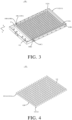
- FIG. 3 is a schematic structural view of a box provided by the embodiment of the present disclosure.
- the battery pack 1 includes a box cover 50 and a box body 10.
- the box body 10 includes a bottom plate 111 and a plurality of side beams 112.
- the plurality of side beams 112 are fixedly arranged on edges of the bottom plate 111 to enclose and define an accommodation cavity 10A.
- the battery module 20, the reinforcement module 12, and the liquid cooling module 30 are all arranged in the accommodation cavity 10A.
- the box cover 50 is arranged opposite to the bottom plate 111, and the box cover 50 is configured to seal the accommodation cavity 10A.
- the box body 10 includes a cross beam 13, the bottom plate 111, and the plurality of side beams 112.
- the plurality of side beams 112 are connected in sequence to form an annular structure, and both ends of the cross beams 13 are in contact with the side beams 112, so that the bottom plate 111, the cross beam 13, and the plurality of side beams 112 define the accommodation cavity 10A for placing the battery module 20.
- the reinforcement module 12 includes a plurality of reinforcement beams 121 arranged at intervals along the first direction X. Both ends of the reinforcement beam 121 are fixedly connected to the side beams 112.
- the liquid cooling module 30 includes a plurality of liquid cooling plates 31 arranged at intervals along the first direction X. The plurality of liquid cooling plates 31 and the plurality of reinforcement beams 121 are alternately arranged along the first direction. One cell group 200 is provided between every adjacent two of the liquid cooling plates 31 and the reinforcement beams 121.
- the battery module 20 includes a plurality of cell group 200 arranged at intervals along the first direction, and each cell group 200 includes a plurality of battery cells 21 arranged at intervals along the second direction Y.
- One cell group 200 is disposed between every adjacent two of the liquid cooling plates 31 and the reinforcement beams 121.
- the reinforcement beam 121 and/or the liquid cooling plate 31 abut/abuts against outer peripheral surfaces of the battery cells 21 located on both sides, and the reinforcement beam 121 and/or the liquid cooling plate 31 match/matches the outer peripheral surface of the battery cell 21.
- each of the reinforcement beam 121 and the liquid cooling plate 31 abuts against the outer peripheral surfaces of the battery cells 21 located on both sides, and the reinforcement beam 121 and the liquid cooling plate 31 all match the outer peripheral surface of the battery cell 21.
- the battery cell 21 is a cylindrical battery cell
- one cell group 200 includes a plurality of cylindrical battery cells.
- the reinforcement beam 121 abuts against the outer periphery surfaces of the cylindrical battery cells 21 located on its both sides.
- the reinforcement beam 121 has a serpentine corrugated structure that matches a cylindrical surface of the cylindrical battery cell 21.
- the liquid cooling plate 31 abuts against the outer peripheral surfaces of the cylindrical battery cells 21 on both sides.
- the liquid cooling plate 31 has a serpentine corrugated structure that matches the cylindrical surface of the cylindrical battery cell 21.
- a thickness of the reinforcement beam 121 is greater than or equal to 1 mm and less than or equal to 4 mm. Inner diameter lengths of adjacent liquid cooling plates 31 are equal.
- the first direction is marked X, and the second direction is marked Y.
- a preset included angle is formed between the first direction X and the second direction Y.
- the thickness of the reinforcement beam 121 is one of 1 mm, 2 mm, and 3 mm, and the preset included angle is a right angle.
- the reinforcement beams 121 are arranged to have the serpentine corrugated structure that matches the cylindrical surface of the battery cell 21, so that a structure of the reinforcement beam 121 is provided between a gap between the adjacent cell groups 200 to increase a space utilization of the battery pack 1.
- the reinforcement beams 121 are evenly distributed, which may effectively disperse the force and reduce stress concentration, thereby reinforcing the strength of the battery pack 1.
- the liquid cooling plate 31 is arranged to abut against the outer peripheral surfaces of the battery cells 21 located on its both sides, and the liquid cooling plate 31 has the serpentine corrugated structure that matches the cylindrical surface of the battery cell 21, so that the liquid cooling plate 31 may be attached to the outer peripheral surfaces of the cylindrical battery cells 21 to improve the cooling effect.
- the plurality of liquid cooling plates 31 and the plurality of reinforcement beams 121 are alternately arranged along the first direction, and every adjacent two of the liquid cooling plates 31 and the reinforcement beams 121 is inserted with one cell group 200, so that each single cell group 200 is independently isolated to prevent the problems that when one single cell group 200 catches fire, other cell groups 200 are caused to undergo a chain of thermal runaway, eventually leading to the battery being scrapped.
- FIG. 4 is a schematic structural view of the reinforcement module provided by the embodiment of the present disclosure
- FIG. 5 is a schematic structural view of the liquid cooling module provided by the embodiment of the present disclosure.
- a plurality of first recesses 10B and a plurality of second recesses 10C are provided on sides of the side beams 112 close to the reinforcement beams 121.
- the plurality of first recesses 10B and the plurality of second recesses 10C are alternately arranged at intervals along the first direction X.
- First plug-in parts 31A are provided on sides of the liquid cooling plates 31 close to the side beams 112. Each first plug-in part 31A is plugged in a corresponding one of the first recesses 10B.
- Second plug-in parts 121A are provided on sides of the reinforcement beams 121 close to the side beams 112. Each second plug-in part 121A is plugged in a corresponding one of the second recesses 10C.
- the second plug-in part 121A and the second recess 10C are fixed by welding.
- the side beams 112 include a first side beam 112A and a second side beam 112B arranged oppositely. One end of the cross beam 13 is in contact with the first side beam 112A, and the other end of the cross beam 13 is in contact with the second side beam 112B.
- the reinforcement beams 121 are located between the first side beam 112A and the second side beam 112B, and an extending direction of the reinforcement beam 121 is parallel to an extending direction of the cross beam 13.
- the liquid cooling plates 31 are located between the first side beam 112A and the second side beam 112B, and an extending direction of the liquid cooling plate 31 is parallel to the extending direction of the cross beam 13.
- Each first recess 10B includes a first sub-recess 10B1 and a third sub-recess 10B2, and each second recess 10C includes a second sub-recess 10C1 and a fourth sub-recess 10C2.
- one side of the first side beam 112A close to the reinforcement module 12 is provided with a plurality of first sub-recesses 10B1 and a plurality of second sub-recesses 10C1, and the plurality of first sub-recesses 10B1 and the plurality of second sub-recesses 10C1 are alternately arranged at intervals along the first direction X.
- One side of the second side beam 112B close to the reinforcement module 12 is provided with a plurality of third sub-recesses 10B2 and a plurality of fourth sub-recesses 10C2, and the plurality of third sub-recesses 10B2 and the plurality of fourth sub-recesses 10C2 are alternately arranged at intervals along the first direction X.
- One first sub-recess 10B1 is arranged corresponding to one third sub-recess 10B2, and one liquid cooling plate 31 is located between one first sub-recess 10B1 and the corresponding one third sub-recess 10B2.
- One second sub-recess 10C1 is arranged corresponding to one fourth sub-recess 10C2, and one reinforcement beam 121 is located between one second sub-recess 10C1 and the corresponding one fourth sub-recess 10C2.
- Each first plug-in part 31A includes a first plug-in sub-part 31A1 and a second plug-in sub-part 31A2, and each second plug-in part 121A includes a third plug-in sub-part 121A1 and a fourth plug-in sub-part 121A2.
- the liquid cooling plate 31 includes one first plug-in sub-part 31A1 and one second plug-in sub-part 31A2.
- the liquid cooling plate 31 is plugged in the first sub-recess 10B1 through the first plug-in sub-part 31A1 and plugged in the third sub-recess 10B2 through the second plug-in sub-part 31A2.
- the reinforcement beam 121 includes one third plug-in sub-part 121A1 and one fourth plug-in sub-part 121A1.
- the reinforcement beam 121 is plugged in the second sub-recess 10C1 through the third plug-in sub-part 121A1 and plugged in the fourth sub-recess 10C2 through the fourth plug-in sub-part 121A2.
- the third plug-in sub-part 121A1 and the second sub-recess 10C1 are fixed by welding.
- the fourth plug-in sub-part 121A2 and the fourth sub-recess 10C2 are fixed by welding.
- the liquid cooling plate 31 is plugged in the first sub-recess 10B1 through the first plug-in sub-part 31A1 and plugged in the third sub-recess 10B2 through the second plug-in sub-part 31A2, and the reinforcement beam 121 is plugged in the second sub-recess 10C1 through the third plug-in sub-part 121A1 and plugged in the fourth sub-recess 10C2 through the fourth plug-in sub-part 121A2, thereby improving an assembly efficiency when assembling the liquid cooling plate 31 and the reinforcement beam 121 and improving a production capacity of the battery pack 1.
- the first sub-recess 10B1 and the third sub-recess 10B2 are provided for limiting a position of the liquid cooling plate 31, the third plug-in sub-part 121A1 and the second sub-recess 10C1 are fixed by welding, and the fourth plug-in sub-part 121A2 and the fourth sub-recess 10C2 are fixed by welding, and the second sub-recess 10C1 and the fourth sub-recess 10C2 are provided for limiting a position of the reinforcement beam 121, which may prevent the liquid cooling plate 31 and the reinforcement beam 121 from moving when the battery pack 1 suffers an external impact, thereby improving the stability of the battery pack 1.
- the embodiment does not specifically limit positions of the recesses and the plug-in parts.
- the embodiment illustrates the technical solution of the present disclosure by only taking an example that sides of the side beams 112 close to the reinforcement beams 121 are provided with the plurality of first recesses 10B and the plurality of second recesses 10C alternately arranged at intervals along the first direction X, sides of the liquid cooling plates 31 close to the side beams 112 are provided with first plug-in parts 31A, and sides of the reinforcement beams 121 close to the side beams 112 are provided with second plug-in parts 121A.
- sides of the side beams 112 close to the reinforcement beams 121 are provide with a plurality of first plug-in parts 31A and a plurality of second plug-in parts 121A alternately arranged along the first direction X
- sides of the liquid cooling plate 31 close to the side beams 112 are provided with first recesses 10B
- sides of the reinforcement beams 121 close to the side beams 112 are provided with second recesses 10C.
- the battery pack 1 further includes a colloidal unit 40, and the colloidal unit 40 is sleeved on the outer surface of each battery cell 21.
- the colloid unit 40 is provided in the accommodation cavity 10A.
- the colloid unit 40 includes but is not limited to a foam rubber 41.
- the foam rubber 41 is provided with a plurality of openings (not shown in the figures). One opening is provided corresponding to one battery cell 21, and the outer surface of the battery cell 21 and an inner wall of the opening are bonded to each other.
- the battery cell 21 passes through the opening and is fixed on the bottom plate 111, and the foam rubber fills the gap between adjacent battery cells 21, thereby avoiding contact collision between the adjacent battery cells 21 during operation and playing the role of buffering.
- the foam rubber also has heat insulation properties, which may effectively reduce the risk of transmission of thermal runaway to adjacent battery cells 21 when single or multiple battery cells 21 in the battery module 20 suffer from the thermal runaway or overheating, thereby preventing the spread of thermal runaway and improving the safety of the battery module 20, i.e. avoiding the problems in the related art that multiple or even all battery cells are caused to undergo a chain of thermal runaway when one single battery cell suffers from thermal runaway, which makes the battery cells unable to be replaced and can only be scrapped, increasing the costs of the battery module.
- the reinforcement beams 121, the liquid cooling plates 31 and the colloid unit 40 are configured to make each single battery cell 21 being independently isolated and fireproofed, which may prevent the heat from being transferred to adjacent single battery cell 21 when one single battery cell 21 suffers from thermal runaway, thereby avoiding the problems in the related art that multiple or even all battery cells 21 are caused to undergo a chain of thermal runaway when one single battery cell 21 suffers from thermal runaway, which makes the battery cells 21 unable to be replaced and can only be scrapped, increasing the costs of the battery module 20, so that the safety of the battery pack 1 is improved.
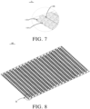
- FIG. 6 is a schematic structural view of a support frame 14 provided by an embodiment of the present disclosure
- FIG. 7 is an enlarged schematic view of part A in FIG. 6 .
- the box body 10 further includes the support frame 14 disposed between the bottom plate 111 and the battery module 20.
- the support frame 14 is fixedly connected to the reinforcement module 12 and the bottom plate 111.
- the support frame 14 is provided with a plurality of installation slots 14A.
- a depth of the installation slot 14A is less than a thickness of the support frame 14.
- One installation slot 14A is arranged corresponding to one battery cell 21, and the battery cell 21 is placed in the installation slot 14A.
- the installation slot 14A is a groove formed by recessing the support frame 14 toward one side facing away from the battery module 20, and a shape of the installation slot 14A matches that of the battery cell 21. Furthermore, the installation slot 14A is cylindrical, and an inner wall of the installation slot 14A is in contact with the outer peripheral surface of the battery cell 21.
- the battery cells 21 are placed in the installation slots 14A, and one installation slot is provided corresponding to one battery cell 21, so that multiple battery cells 21 may be installed at the same time during assembly, which greatly improves the assembly efficiency of the battery pack 1, ensures assembly accuracy, and is easy to realize automation.
- a structural glue may be used to fixedly connect the support frame 14 and the battery cells 21, which makes the connection convenient and reliable and effectively prevents the battery cells 21 from loosening and falling off.
- a pressure relief cavity is defined and enclosed between the support frame 14, the bottom plate 111, and the side beams 112.
- the support frame 14 also has a plurality of through holes 14A1.
- One through hole 14A1 is provided corresponding to one installation slot 14A.
- a diameter of the through hole 14A1 is less than a diameter of the installation slot 14A.
- the through hole 14A1 passes through the installation slot 14A, and the through hole 14A1 is communicated with the pressure relief cavity.
- the through holes 14A1 are pressure relief holes, the diameter of the through hole 14A1 is less than the diameter of the installation slot 14A, and the pressure relief cavity communicates with the installation slots 14A through the through holes 14A1.
- a design of the pressure relief cavity reduces an impact when the battery cell 21 bursts and improves the operation safety of the battery module 20.
- the through holes 14A1 may quickly export the heat of the battery cells 21 or the gas generated when the battery cell is thermal out of control from the bottom of the battery cell 21, enhance the heat dissipation effect, and increase the safety performance of the battery pack 1.
- a material of the box body is metal
- the support frame 14 is made of plastic or other materials with good insulation.
- a placement part located on the bottom of the installation slot 14A prevents a bottom surface of the battery cell 21 from being in contact with the bottom plate 111 and plays an insulating and protective role.
- one of the support frame 14 and the reinforcement beam 121 is provided with fixing holes 14B, and the other one of the support frame 14 and the reinforcement beam 121 is provided with protrusions 12B.
- One protrusion 12B is arranged corresponding to one fixing hole 14B, and the protrusion 12B is clamped in the fixing hole 14B.
- the support frame 14 is provided with the plurality of fixing holes 14B, and each fixing hole 14B penetrates the support frame 14.
- Sides of the reinforcement beams 121 close to the support frame 14 are provided with the plurality of protrusions 12B.
- One protrusion 12B is provided corresponding to one fixing hole 14B, the protrusion 12B is clamped in the fixing hole 14B, and the protrusion 12B and the support frame 14 are fixed by welding.
- the protrusions 12B of the reinforcement beams 121 and the support frame 14 are fixed by spot welding, and welding points are located on one side of the support frame 14 close to the bottom plate 111.
- the support frame 14 is provided with the plurality of installation slots 14A, and the installation slots 14A may reduce the rigidity of the support frame 14.
- the protrusions 12B of the reinforcement beams 121 and the support frame 14 are fixed by spot welding, which increases the rigidity of the support frame 14 and improves the stability of the box body 10.
- the fixing hole 14B is located between the adjacent installation slots 14A.
- the fixing hole 14B and the installation slot 14A are arranged at intervals.
- a diameter of the fixing hole 14B is less than the diameter the through hole 14A1.
- One protrusion 12B is provided corresponding to one fixing hole 14B. The protrusion 12B passes through the fixing hole 14B, the protrusion 12B is fixed to the support frame 14 by welding, and the welding point is located on one side of the support frame 14 facing away from the reinforcement beam 121.
- the support frame 14 is provided with the plurality of fixing holes 14B, sides of the reinforcement beams 121 close to the support frame 14 are provided with the plurality of protrusions 12B, the protrusions 12B are clamped in the fixing holes 14B, and the protrusions 12B and the support frame 14 are fixed by welding, so that a fixing strength between the reinforcement beam 121 and the support frame 14 is enhanced, thereby increasing a structural strength of the box body 10.
- the support frame 14 may provide a certain supporting force to the battery module 20, effectively improving the installation stability of the battery module 20, thereby further improving the protection effect of the box body 10 on battery module 20.
- FIG. 8 is a schematic structural view of a CCS assembly provided by an embodiment of the present disclosure
- FIG. 9 is an enlarged schematic view of part B in FIG. 8 .
- the battery pack 1 further includes a cell contacting system (CCS) assembly 60 disposed on one side of the battery module 20 facing away from the bottom plate 111.
- the CCS assembly 60 includes a fixing frame 61 and a busbar 62.
- the fixing frame 61 is provided with installation holes 61A, and the busbar 62 is embedded in the installation holes 61A.
- the busbar 62 is disposed in contact with the battery cells 21 and electrically connects the plurality of battery cells 21.
- the busbar 62 is configured to electrically connect the plurality of battery cells 21.
- the busbar 62 includes busbar units 621 and connecting arms 622.
- Each busbar unit 621 includes a positive connecting part 621A and a negative connecting part 621B.
- the installation holes 61A include positive installation holes 61A1 and negative installation holes 61A2.
- the positive connecting part 621A is electrically connected to a positive electrode of the battery cell 21 through the positive installation hole 61A1
- the negative connecting part 621B is electrically connected to a negative electrode of the battery cell 21 through the negative installation hole 61A2.
- the connecting arm 622 is configured to connect two adjacent busbar units 621.
- the busbar 62 in order to electrically connect the plurality of battery cells 21, the busbar 62 is provided on the top of the battery cells 21, the installation holes 61A for installing the busbar 62 are provided on the fixing frame 61, and the busbar 62 is embedded in the installation holes 61A and in contact with the battery cells 21, which effectively prevents the problem of a short circuit between the adjacent battery cells 21 caused by the misalignment of the busbar 62.
- the embodiments also provide an electric equipment, which includes the battery pack described in any of the above embodiments.
- the battery pack includes the battery module, and the battery module is used as a power supply for the electric equipment. Therefore, the electric equipment also has various advantages of the above-mentioned battery module, which simplifies an overall structure of the electric equipment.
- the electric equipment may be a vehicle, an aircraft, or a mechanical production equipment, etc.
Landscapes
- Chemical & Material Sciences (AREA)
- Chemical Kinetics & Catalysis (AREA)
- Electrochemistry (AREA)
- General Chemical & Material Sciences (AREA)
- Engineering & Computer Science (AREA)
- Manufacturing & Machinery (AREA)
- Battery Mounting, Suspending (AREA)
- Secondary Cells (AREA)
Abstract
The present disclosure provides a battery pack (1) and an electric equipment. The battery pack (1) includes a battery module (20), a reinforcement module (12), and a liquid cooling module (30). The battery module (20) includes a plurality of cell groups (200) arranged at intervals along a first direction. Each cell group (200) includes a plurality of battery cells (21) arranged at intervals along a second direction. The reinforcement module (12) includes a plurality of reinforcement beams (121). The liquid cooling module (30) includes a plurality of liquid cooling plates (31). The plurality of liquid cooling plates (31) and the plurality of reinforcement beams (121) are alternately arranged along the first direction. One cell group (200) is provided between every adjacent two of the liquid cooling plates (31) and the reinforcement beams (121).
Description
- The present disclosure relates to the technical field of batteries, and in particular, to a battery pack and an electric equipment.
- As one of core components of an electric vehicle, a power battery is the energy hub of the electric vehicle. A battery pack, as an energy distribution unit of the power battery, plays an irreplaceable role in the entire vehicle. At present, when the battery pack is subjected to thermal abuse, electrical abuse (overcharge, over-discharge, internal short circuit, etc.), or mechanical abuse (extrusion, needle puncture, collision, etc.), battery cells are prone to suffer from thermal runaway and explosion and fire. When one single battery cell catches fire, it will cause other battery cells to undergo a chain of thermal runaway, eventually leading to the battery being scrapped.
- Therefore, there is an urgent need to improve a mechanical strength of the battery pack and isolate adjacent battery cells to avoid chain phenomena of thermal runaway.
- Embodiments of the present disclosure provide a battery pack and an electric equipment to solve or at least partially solve the shortcomings of the above background.
- In a first aspect, embodiments of the present disclosure provide a battery pack. The battery pack includes a battery module, a reinforcement module, and a liquid cooling module. The battery module includes a plurality of cell groups cell groups arranged at intervals along a first direction. Each cell group includes a plurality of battery cells arranged at intervals along a second direction. The reinforcement module includes a plurality of reinforcement beams. The liquid cooling module includes a plurality of liquid cooling plates. The plurality of liquid cooling plates and the plurality of reinforcement beams are alternately arranged along the first direction. One cell group is provided between every adjacent two of the liquid cooling plates and the reinforcement beams.
- In a second aspect, embodiments of the present disclosure provide an electrical device, which includes any one of the battery packs described above.
- Beneficial effects of the embodiments of the present disclosure: Embodiments of the present disclosure provide a battery pack and an electric equipment. The battery pack includes a battery module, a reinforcement module, and a liquid cooling module. The battery module includes a plurality of cell groups arranged at intervals along a first direction. Each cell group includes a plurality of battery cells arranged at intervals along a second direction. The reinforcement module includes a plurality of reinforcement beams. The liquid cooling module includes a plurality of liquid cooling plates. The plurality of liquid cooling plates and the plurality of reinforcement beams are alternately arranged along the first direction. One cell group is provided between every adjacent two of the liquid cooling plates and the reinforcement beams. In the embodiments of the present disclosure, the plurality of liquid cooling plates and the plurality of reinforcement beams are alternately arranged along the first direction, which reinforces the strength of the battery pack and avoids the problems in the related art that the battery cells are prone to suffer from thermal runaway when the battery pack is subjected to thermal abuse, electrical abuse, or mechanical abuse. Furthermore, one cell group is provided between every adjacent two of the liquid cooling plates and the reinforcement beams, so that each single cell group is independently isolated.
- In order to explain the technical solutions in the embodiments more clearly, the drawings needed to be used in the description of the embodiments will be briefly introduced below. Obviously, the drawings in the following description are only some embodiments of the present disclosure. Those skilled in the art may also obtain other drawings based on these drawings without exerting creative efforts.
-
FIG. 1 is a schematic structural view of a battery pack provided by an embodiment of the present disclosure. -
FIG. 2 is an exploded view of the battery pack provided by the embodiment of the present disclosure. -
FIG. 3 is a schematic structural view of a box provided by an embodiment of the present disclosure. -
FIG. 4 is a schematic structural view of a reinforcement module provided by an embodiment of the present disclosure. -
FIG. 5 is a schematic structural view of a liquid cooling module provided by an embodiment of the present disclosure. -
FIG. 6 is a schematic structural view of a support frame provided by an embodiment of the present disclosure. -
FIG. 7 is an enlarged schematic view of part A inFIG. 6 . -
FIG. 8 is a schematic structural view of a CCS assembly provided by an embodiment of the present disclosure. -
FIG. 9 is an enlarged schematic view of part B inFIG. 8 . - 1, battery pack; 10, box body; 20, battery module; 30, liquid cooling module; 40, colloidal unit; 50, box cover; 60, CCS assembly; 10A, accommodating cavity; 10B, first recess; 10C, second recess; 10B1, first sub-recess; 10C1, second sub-recess; 10B2, third sub-recess; 10C2, fourth sub-recess; 12, reinforcement module; 13, cross beam; 14, support frame; 111, bottom plate; 112, side beam; 112A, first side beam; 112B, second side beam; 12B, protrusion; 121, reinforcement beam; 121A, second plug-in part; 121A1, third plug-in sub-part; 121A2, fourth plug-in sub-part; 14A, installation slot; 14A1, through hole; 14B, fixing hole; 200, cell group; 21, battery cell; 31, liquid cooling plate; 31A, first plug-in part; 31A1, first plug-in sub-part; 31A2, second plug-in sub-part; 41, foam rubber; 61, fixing frame; 62, busbar; 61A, installation hole; 61A1, positive installation hole; 61A2, negative pole installation hole; 621, busbar unit; 622, connecting arm; 621A, positive connecting part; 621B, negative connecting part.
- The technical solutions in the embodiments will be clearly and completely described below with reference to the accompanying drawings in the embodiments. Obviously, the described embodiments are only some of the embodiments of the present disclosure, rather than all of the embodiments. Based on the embodiments in the present disclosure, all other embodiments obtained by those skilled in the art without making creative efforts fall within the protection scope of the present disclosure. In addition, it should be understood that the specific embodiments described here are only used to illustrate and explain the invention, and are not intended to limit the invention. In the present disclosure, unless otherwise specified, the orientational terms such as "upper" and "lower" usually refer to the upper and lower positions of the device in actual use or working conditions, specifically the orientations in the drawings. The terms "Inside" and "outside" refer to the outline of the device.
- The embodiments provide a battery pack and an electric equipment. Each is explained in detail below. It should be noted that the order of description of the following embodiments does not limit the preferred order of the embodiments.
- Referring to
FIG. 1 to FIG. 9 , the embodiments provides a battery pack and an electric equipment. Thebattery pack 1 includes abattery module 20, areinforcement module 12, and aliquid cooling module 30. Thebattery module 20 includes a plurality ofcell groups 200 arranged at intervals along a first direction X, and eachcell group 200 includes a plurality ofbattery cells 21 arranged at intervals along a second direction Y. Thereinforcement module 12 includes a plurality ofreinforcement beams 121, theliquid cooling module 30 includes a plurality ofliquid cooling plates 31, and the plurality ofliquid cooling plates 31 and the plurality ofreinforcement beams 121 are arranged alternately along the first direction X. Onecell group 200 is provided between every adjacent two of theliquid cooling plates 31 and thereinforcement beams 121. - It should be noted that in related arts, when the battery pack is subjected to thermal abuse, electrical abuse (overcharge, over-discharge, internal short circuit, etc.), or mechanical abuse (extrusion, needle puncture, collision, etc.), the battery cells are prone to suffer from thermal runaway and explosion and fire. When one single battery cell catches fire, it will cause other battery cells to undergo a chain of thermal runaway, eventually leading to the battery being scrapped.
- It can be understood that in the embodiments the plurality of liquid cooling plates and the plurality of reinforcement beams are alternately arranged along the first direction, which reinforces the strength of the battery pack and avoids the problems in the related art that the battery cells are prone to suffer from thermal runaway when the battery pack is subjected to thermal abuse, electrical abuse, or mechanical abuse. Furthermore, one cell group is provided between every adjacent two of the liquid cooling plates and the reinforcement beams, so that each single cell group may be independently isolated.
- The technical solutions of the present disclosure will now be described with reference to specific embodiments.
- In an embodiment, referring to
FIG. 1, FIG. 2 andFIG. 3 ,FIG. 1 is a a schematic structural view of a battery pack provided by the embodiment of the present disclosure,FIG. 2 is an exploded view of the battery pack provided by the embodiment of the present disclosure, andFIG. 3 is a schematic structural view of a box provided by the embodiment of the present disclosure. - In the embodiment, the
battery pack 1 includes abox cover 50 and abox body 10. Thebox body 10 includes abottom plate 111 and a plurality of side beams 112. The plurality ofside beams 112 are fixedly arranged on edges of thebottom plate 111 to enclose and define anaccommodation cavity 10A. Thebattery module 20, thereinforcement module 12, and theliquid cooling module 30 are all arranged in theaccommodation cavity 10A. Thebox cover 50 is arranged opposite to thebottom plate 111, and thebox cover 50 is configured to seal theaccommodation cavity 10A. - In the embodiment, the
box body 10 includes across beam 13, thebottom plate 111, and the plurality of side beams 112. The plurality ofside beams 112 are connected in sequence to form an annular structure, and both ends of the cross beams 13 are in contact with the side beams 112, so that thebottom plate 111, thecross beam 13, and the plurality ofside beams 112 define theaccommodation cavity 10A for placing thebattery module 20. - Furthermore, the
reinforcement module 12 includes a plurality ofreinforcement beams 121 arranged at intervals along the first direction X. Both ends of thereinforcement beam 121 are fixedly connected to the side beams 112. Theliquid cooling module 30 includes a plurality ofliquid cooling plates 31 arranged at intervals along the first direction X. The plurality ofliquid cooling plates 31 and the plurality ofreinforcement beams 121 are alternately arranged along the first direction. Onecell group 200 is provided between every adjacent two of theliquid cooling plates 31 and the reinforcement beams 121. - The
battery module 20 includes a plurality ofcell group 200 arranged at intervals along the first direction, and eachcell group 200 includes a plurality ofbattery cells 21 arranged at intervals along the second direction Y. Onecell group 200 is disposed between every adjacent two of theliquid cooling plates 31 and the reinforcement beams 121. Specifically, in the embodiment, thereinforcement beam 121 and/or theliquid cooling plate 31 abut/abuts against outer peripheral surfaces of thebattery cells 21 located on both sides, and thereinforcement beam 121 and/or theliquid cooling plate 31 match/matches the outer peripheral surface of thebattery cell 21. Preferably, in the embodiment, each of thereinforcement beam 121 and theliquid cooling plate 31 abuts against the outer peripheral surfaces of thebattery cells 21 located on both sides, and thereinforcement beam 121 and theliquid cooling plate 31 all match the outer peripheral surface of thebattery cell 21. - Specifically, in the embodiment, the
battery cell 21 is a cylindrical battery cell, and onecell group 200 includes a plurality of cylindrical battery cells. Thereinforcement beam 121 abuts against the outer periphery surfaces of thecylindrical battery cells 21 located on its both sides. Thereinforcement beam 121 has a serpentine corrugated structure that matches a cylindrical surface of thecylindrical battery cell 21. Theliquid cooling plate 31 abuts against the outer peripheral surfaces of thecylindrical battery cells 21 on both sides. Theliquid cooling plate 31 has a serpentine corrugated structure that matches the cylindrical surface of thecylindrical battery cell 21. - It should be noted that in the embodiment, a thickness of the
reinforcement beam 121 is greater than or equal to 1 mm and less than or equal to 4 mm. Inner diameter lengths of adjacentliquid cooling plates 31 are equal. The first direction is marked X, and the second direction is marked Y. A preset included angle is formed between the first direction X and the second direction Y. Preferably, the thickness of thereinforcement beam 121 is one of 1 mm, 2 mm, and 3 mm, and the preset included angle is a right angle. - It can be understood that in the embodiments, the reinforcement beams 121 are arranged to have the serpentine corrugated structure that matches the cylindrical surface of the
battery cell 21, so that a structure of thereinforcement beam 121 is provided between a gap between theadjacent cell groups 200 to increase a space utilization of thebattery pack 1. The reinforcement beams 121 are evenly distributed, which may effectively disperse the force and reduce stress concentration, thereby reinforcing the strength of thebattery pack 1. At the same time, theliquid cooling plate 31 is arranged to abut against the outer peripheral surfaces of thebattery cells 21 located on its both sides, and theliquid cooling plate 31 has the serpentine corrugated structure that matches the cylindrical surface of thebattery cell 21, so that theliquid cooling plate 31 may be attached to the outer peripheral surfaces of thecylindrical battery cells 21 to improve the cooling effect. Furthermore, the plurality ofliquid cooling plates 31 and the plurality ofreinforcement beams 121 are alternately arranged along the first direction, and every adjacent two of theliquid cooling plates 31 and the reinforcement beams 121 is inserted with onecell group 200, so that eachsingle cell group 200 is independently isolated to prevent the problems that when onesingle cell group 200 catches fire,other cell groups 200 are caused to undergo a chain of thermal runaway, eventually leading to the battery being scrapped. - Furthermore, please refer to
FIG. 1 ,FIG. 3 ,FIG. 4 , andFIG. 5 ,FIG. 4 is a schematic structural view of the reinforcement module provided by the embodiment of the present disclosure, andFIG. 5 is a schematic structural view of the liquid cooling module provided by the embodiment of the present disclosure. - In the embodiment, a plurality of
first recesses 10B and a plurality ofsecond recesses 10C are provided on sides of the side beams 112 close to the reinforcement beams 121. The plurality offirst recesses 10B and the plurality ofsecond recesses 10C are alternately arranged at intervals along the first direction X. First plug-inparts 31A are provided on sides of theliquid cooling plates 31 close to the side beams 112. Each first plug-inpart 31A is plugged in a corresponding one of thefirst recesses 10B. Second plug-inparts 121A are provided on sides of the reinforcement beams 121 close to the side beams 112. Each second plug-inpart 121A is plugged in a corresponding one of thesecond recesses 10C. Specifically, the second plug-inpart 121A and thesecond recess 10C are fixed by welding. - In the embodiment, the side beams 112 include a
first side beam 112A and asecond side beam 112B arranged oppositely. One end of thecross beam 13 is in contact with thefirst side beam 112A, and the other end of thecross beam 13 is in contact with thesecond side beam 112B. The reinforcement beams 121 are located between thefirst side beam 112A and thesecond side beam 112B, and an extending direction of thereinforcement beam 121 is parallel to an extending direction of thecross beam 13. Theliquid cooling plates 31 are located between thefirst side beam 112A and thesecond side beam 112B, and an extending direction of theliquid cooling plate 31 is parallel to the extending direction of thecross beam 13. - Each
first recess 10B includes a first sub-recess 10B1 and a third sub-recess 10B2, and eachsecond recess 10C includes a second sub-recess 10C1 and a fourth sub-recess 10C2. Specifically, one side of thefirst side beam 112A close to thereinforcement module 12 is provided with a plurality of first sub-recesses 10B1 and a plurality of second sub-recesses 10C1, and the plurality of first sub-recesses 10B1 and the plurality of second sub-recesses 10C1 are alternately arranged at intervals along the first direction X. One side of thesecond side beam 112B close to thereinforcement module 12 is provided with a plurality of third sub-recesses 10B2 and a plurality of fourth sub-recesses 10C2, and the plurality of third sub-recesses 10B2 and the plurality of fourth sub-recesses 10C2 are alternately arranged at intervals along the first direction X. One first sub-recess 10B1 is arranged corresponding to one third sub-recess 10B2, and oneliquid cooling plate 31 is located between one first sub-recess 10B1 and the corresponding one third sub-recess 10B2. One second sub-recess 10C1 is arranged corresponding to one fourth sub-recess 10C2, and onereinforcement beam 121 is located between one second sub-recess 10C1 and the corresponding one fourth sub-recess 10C2. - Each first plug-in
part 31A includes a first plug-in sub-part 31A1 and a second plug-in sub-part 31A2, and each second plug-inpart 121A includes a third plug-in sub-part 121A1 and a fourth plug-in sub-part 121A2. Specifically, theliquid cooling plate 31 includes one first plug-in sub-part 31A1 and one second plug-in sub-part 31A2. Theliquid cooling plate 31 is plugged in the first sub-recess 10B1 through the first plug-in sub-part 31A1 and plugged in the third sub-recess 10B2 through the second plug-in sub-part 31A2. Thereinforcement beam 121 includes one third plug-in sub-part 121A1 and one fourth plug-in sub-part 121A1. Thereinforcement beam 121 is plugged in the second sub-recess 10C1 through the third plug-in sub-part 121A1 and plugged in the fourth sub-recess 10C2 through the fourth plug-in sub-part 121A2. The third plug-in sub-part 121A1 and the second sub-recess 10C1 are fixed by welding. The fourth plug-in sub-part 121A2 and the fourth sub-recess 10C2 are fixed by welding. - It can be understood that in the embodiment, the
liquid cooling plate 31 is plugged in the first sub-recess 10B1 through the first plug-in sub-part 31A1 and plugged in the third sub-recess 10B2 through the second plug-in sub-part 31A2, and thereinforcement beam 121 is plugged in the second sub-recess 10C1 through the third plug-in sub-part 121A1 and plugged in the fourth sub-recess 10C2 through the fourth plug-in sub-part 121A2, thereby improving an assembly efficiency when assembling theliquid cooling plate 31 and thereinforcement beam 121 and improving a production capacity of thebattery pack 1. At the same time, the first sub-recess 10B1 and the third sub-recess 10B2 are provided for limiting a position of theliquid cooling plate 31, the third plug-in sub-part 121A1 and the second sub-recess 10C1 are fixed by welding, and the fourth plug-in sub-part 121A2 and the fourth sub-recess 10C2 are fixed by welding, and the second sub-recess 10C1 and the fourth sub-recess 10C2 are provided for limiting a position of thereinforcement beam 121, which may prevent theliquid cooling plate 31 and thereinforcement beam 121 from moving when thebattery pack 1 suffers an external impact, thereby improving the stability of thebattery pack 1. - It should be noted that the embodiment does not specifically limit positions of the recesses and the plug-in parts. The embodiment illustrates the technical solution of the present disclosure by only taking an example that sides of the side beams 112 close to the reinforcement beams 121 are provided with the plurality of
first recesses 10B and the plurality ofsecond recesses 10C alternately arranged at intervals along the first direction X, sides of theliquid cooling plates 31 close to the side beams 112 are provided with first plug-inparts 31A, and sides of the reinforcement beams 121 close to the side beams 112 are provided with second plug-inparts 121A. - For example, in another embodiment, sides of the side beams 112 close to the reinforcement beams 121 are provide with a plurality of first plug-in
parts 31A and a plurality of second plug-inparts 121A alternately arranged along the first direction X, sides of theliquid cooling plate 31 close to the side beams 112 are provided withfirst recesses 10B, and sides of the reinforcement beams 121 close to the side beams 112 are provided withsecond recesses 10C. - Furthermore, in the embodiment, the
battery pack 1 further includes acolloidal unit 40, and thecolloidal unit 40 is sleeved on the outer surface of eachbattery cell 21. Specifically, thecolloid unit 40 is provided in theaccommodation cavity 10A. Thecolloid unit 40 includes but is not limited to afoam rubber 41. Thefoam rubber 41 is provided with a plurality of openings (not shown in the figures). One opening is provided corresponding to onebattery cell 21, and the outer surface of thebattery cell 21 and an inner wall of the opening are bonded to each other. - Specifically, the
battery cell 21 passes through the opening and is fixed on thebottom plate 111, and the foam rubber fills the gap betweenadjacent battery cells 21, thereby avoiding contact collision between theadjacent battery cells 21 during operation and playing the role of buffering. In addition, the foam rubber also has heat insulation properties, which may effectively reduce the risk of transmission of thermal runaway toadjacent battery cells 21 when single ormultiple battery cells 21 in thebattery module 20 suffer from the thermal runaway or overheating, thereby preventing the spread of thermal runaway and improving the safety of thebattery module 20, i.e. avoiding the problems in the related art that multiple or even all battery cells are caused to undergo a chain of thermal runaway when one single battery cell suffers from thermal runaway, which makes the battery cells unable to be replaced and can only be scrapped, increasing the costs of the battery module. - It can be understood that in the embodiment, the reinforcement beams 121, the
liquid cooling plates 31 and thecolloid unit 40 are configured to make eachsingle battery cell 21 being independently isolated and fireproofed, which may prevent the heat from being transferred to adjacentsingle battery cell 21 when onesingle battery cell 21 suffers from thermal runaway, thereby avoiding the problems in the related art that multiple or even allbattery cells 21 are caused to undergo a chain of thermal runaway when onesingle battery cell 21 suffers from thermal runaway, which makes thebattery cells 21 unable to be replaced and can only be scrapped, increasing the costs of thebattery module 20, so that the safety of thebattery pack 1 is improved. - Furthermore, referring to
FIG. 1, FIG. 2 ,FIG. 6 , andFIG. 7 ,FIG. 6 is a schematic structural view of asupport frame 14 provided by an embodiment of the present disclosure, andFIG. 7 is an enlarged schematic view of part A inFIG. 6 . - In the embodiment, the
box body 10 further includes thesupport frame 14 disposed between thebottom plate 111 and thebattery module 20. Thesupport frame 14 is fixedly connected to thereinforcement module 12 and thebottom plate 111. Thesupport frame 14 is provided with a plurality ofinstallation slots 14A. A depth of theinstallation slot 14A is less than a thickness of thesupport frame 14. Oneinstallation slot 14A is arranged corresponding to onebattery cell 21, and thebattery cell 21 is placed in theinstallation slot 14A. - Specifically, in the embodiment, the
installation slot 14A is a groove formed by recessing thesupport frame 14 toward one side facing away from thebattery module 20, and a shape of theinstallation slot 14A matches that of thebattery cell 21. Furthermore, theinstallation slot 14A is cylindrical, and an inner wall of theinstallation slot 14A is in contact with the outer peripheral surface of thebattery cell 21. In the embodiment, thebattery cells 21 are placed in theinstallation slots 14A, and one installation slot is provided corresponding to onebattery cell 21, so thatmultiple battery cells 21 may be installed at the same time during assembly, which greatly improves the assembly efficiency of thebattery pack 1, ensures assembly accuracy, and is easy to realize automation. A structural glue may be used to fixedly connect thesupport frame 14 and thebattery cells 21, which makes the connection convenient and reliable and effectively prevents thebattery cells 21 from loosening and falling off. - In the embodiment, a pressure relief cavity is defined and enclosed between the
support frame 14, thebottom plate 111, and the side beams 112. Thesupport frame 14 also has a plurality of through holes 14A1. One through hole 14A1 is provided corresponding to oneinstallation slot 14A. A diameter of the through hole 14A1 is less than a diameter of theinstallation slot 14A. The through hole 14A1 passes through theinstallation slot 14A, and the through hole 14A1 is communicated with the pressure relief cavity. - Specifically, in the embodiment, the through holes 14A1 are pressure relief holes, the diameter of the through hole 14A1 is less than the diameter of the
installation slot 14A, and the pressure relief cavity communicates with theinstallation slots 14A through the through holes 14A1. A design of the pressure relief cavity reduces an impact when thebattery cell 21 bursts and improves the operation safety of thebattery module 20. At the same time, the through holes 14A1 may quickly export the heat of thebattery cells 21 or the gas generated when the battery cell is thermal out of control from the bottom of thebattery cell 21, enhance the heat dissipation effect, and increase the safety performance of thebattery pack 1. It should be noted that in the embodiment, a material of the box body is metal, thesupport frame 14 is made of plastic or other materials with good insulation. A placement part located on the bottom of theinstallation slot 14A prevents a bottom surface of thebattery cell 21 from being in contact with thebottom plate 111 and plays an insulating and protective role. - In the embodiment, one of the
support frame 14 and thereinforcement beam 121 is provided with fixingholes 14B, and the other one of thesupport frame 14 and thereinforcement beam 121 is provided withprotrusions 12B. Oneprotrusion 12B is arranged corresponding to one fixinghole 14B, and theprotrusion 12B is clamped in the fixinghole 14B. - Preferably, in the embodiment, the
support frame 14 is provided with the plurality of fixingholes 14B, and each fixinghole 14B penetrates thesupport frame 14. Sides of the reinforcement beams 121 close to thesupport frame 14 are provided with the plurality ofprotrusions 12B. Oneprotrusion 12B is provided corresponding to one fixinghole 14B, theprotrusion 12B is clamped in the fixinghole 14B, and theprotrusion 12B and thesupport frame 14 are fixed by welding. Preferably, theprotrusions 12B of the reinforcement beams 121 and thesupport frame 14 are fixed by spot welding, and welding points are located on one side of thesupport frame 14 close to thebottom plate 111. - It can be understood that the
support frame 14 is provided with the plurality ofinstallation slots 14A, and theinstallation slots 14A may reduce the rigidity of thesupport frame 14. In the embodiment, theprotrusions 12B of the reinforcement beams 121 and thesupport frame 14 are fixed by spot welding, which increases the rigidity of thesupport frame 14 and improves the stability of thebox body 10. - Specifically, in the embodiment, the fixing
hole 14B is located between theadjacent installation slots 14A. The fixinghole 14B and theinstallation slot 14A are arranged at intervals. A diameter of the fixinghole 14B is less than the diameter the through hole 14A1. Oneprotrusion 12B is provided corresponding to one fixinghole 14B. Theprotrusion 12B passes through the fixinghole 14B, theprotrusion 12B is fixed to thesupport frame 14 by welding, and the welding point is located on one side of thesupport frame 14 facing away from thereinforcement beam 121. - It can be understood that in the embodiment, the
support frame 14 is provided with the plurality of fixingholes 14B, sides of the reinforcement beams 121 close to thesupport frame 14 are provided with the plurality ofprotrusions 12B, theprotrusions 12B are clamped in the fixingholes 14B, and theprotrusions 12B and thesupport frame 14 are fixed by welding, so that a fixing strength between thereinforcement beam 121 and thesupport frame 14 is enhanced, thereby increasing a structural strength of thebox body 10. At the same time, when collision occurs, thesupport frame 14 may provide a certain supporting force to thebattery module 20, effectively improving the installation stability of thebattery module 20, thereby further improving the protection effect of thebox body 10 onbattery module 20. - Furthermore, referring to
FIG. 1, FIG. 2 ,FIG. 8 , andFIG. 9 ,FIG. 8 is a schematic structural view of a CCS assembly provided by an embodiment of the present disclosure, andFIG. 9 is an enlarged schematic view of part B inFIG. 8 . - In the embodiment, the
battery pack 1 further includes a cell contacting system (CCS)assembly 60 disposed on one side of thebattery module 20 facing away from thebottom plate 111. TheCCS assembly 60 includes a fixingframe 61 and a busbar 62. The fixingframe 61 is provided withinstallation holes 61A, and the busbar 62 is embedded in theinstallation holes 61A. The busbar 62 is disposed in contact with thebattery cells 21 and electrically connects the plurality ofbattery cells 21. - Specifically, the busbar 62 is configured to electrically connect the plurality of
battery cells 21. The busbar 62 includesbusbar units 621 and connectingarms 622. Eachbusbar unit 621 includes a positive connecting part 621A and a negative connecting part 621B. The installation holes 61A include positive installation holes 61A1 and negative installation holes 61A2. The positive connecting part 621A is electrically connected to a positive electrode of thebattery cell 21 through the positive installation hole 61A1, and the negative connecting part 621B is electrically connected to a negative electrode of thebattery cell 21 through the negative installation hole 61A2. The connectingarm 622 is configured to connect twoadjacent busbar units 621. It can be understood that in the embodiment, in order to electrically connect the plurality ofbattery cells 21, the busbar 62 is provided on the top of thebattery cells 21, theinstallation holes 61A for installing the busbar 62 are provided on the fixingframe 61, and the busbar 62 is embedded in theinstallation holes 61A and in contact with thebattery cells 21, which effectively prevents the problem of a short circuit between theadjacent battery cells 21 caused by the misalignment of the busbar 62. - The embodiments also provide an electric equipment, which includes the battery pack described in any of the above embodiments.
- It can be understood that the battery pack has been described in detail in the above embodiments, and the description will not be repeated here.
- The battery pack includes the battery module, and the battery module is used as a power supply for the electric equipment. Therefore, the electric equipment also has various advantages of the above-mentioned battery module, which simplifies an overall structure of the electric equipment. The electric equipment may be a vehicle, an aircraft, or a mechanical production equipment, etc.
- In the above embodiments, each embodiment is described with its own emphasis. For parts that are not described in detail in a certain embodiment, please refer to the relevant descriptions of other embodiments.
- The above is a detailed introduction to the battery pack and the electric equipment provided by the embodiments. Specific examples are used in this paper to illustrate the principles and implementation methods of the present disclosure. The description of the above embodiments is only used to help understand methods and core ideas of the present disclosure. At the same time, for those skilled in the art, there will be changes in the specific implementation and application scope based on the ideas of the present disclosure. In summary, the content of the description should not be understood as a limitation of the present disclosure.
Claims (15)
- A battery pack (1), characterized by comprising:a battery module (20), comprising a plurality of cell groups (200) arranged at intervals along a first direction, wherein each of the cell groups (200) comprises a plurality of battery cells (21) arranged at intervals along a second direction;a reinforcement module (12), comprising a plurality of reinforcement beams (121); anda liquid cooling module (30), comprising a plurality of liquid cooling plates (31),wherein the plurality of liquid cooling plates (31) and the plurality of reinforcement beams (121) are arranged alternately along the first direction, and every adjacent two of the liquid cooling plates (31) and the reinforcement beams (121) are inserted with one of the cell groups (200).
- The battery pack according to claim 1, characterized by comprising a box body(10), wherein the box body(10) comprises a bottom plate (111) and a plurality of side beams (112), the plurality of side beams (112) are fixedly arranged on edges of the bottom plate (111) to enclose and define an accommodating cavity (10A); and
wherein the battery module (20), the reinforcement module (12), and the liquid cooling module (30) are all arranged in the accommodating cavity (10A), and both ends of each of the reinforcement beams (121) and the liquid cooling plates (31) are fixedly connected to the side beams (112). - The battery pack according to claim 2, characterized in that, each of the reinforcement beams (121) and/or the liquid cooling plates (31) abuts against outer peripheral surfaces of the battery cells (21) located on both sides, and each of the reinforcement beams (121) and/or the liquid cooling plates (31) matches the outer peripheral surfaces of the battery cells (21).
- The battery pack according to claim 3, characterized in that, each of the battery cells (21) is a cylindrical battery cell, and each of the reinforcement beams (121) and/or the liquid cooling plates (31) has a serpentine corrugated structure that matches a cylindrical surface of the cylindrical battery cell.
- The battery pack according to any one of claims 2-4, characterized in that, a plurality of first recesses (10B) and a plurality of second recesses (10C) are provided on sides of the side beams (112) close to the reinforcement beams (121), and the plurality of first recesses (10B) and the plurality of second recesses (10C) are alternately arranged at intervals along the first direction;first plug-in parts (31A) are provided on sides of the liquid cooling plates (31) close to the side beams (112), and each of the first plug-in parts (31A) is plugged in a corresponding one of the first recesses (10B); andsecond plug-in parts (121A) are provided on sides of the reinforcement beams (121) close to the side beams (112), and each of the second plug-in parts (121A) is plugged in a corresponding one of the second recesses (10C).
- The battery pack according to claim 5, characterized in that, the second plug-in parts (121A) and the second recesses (10C) are fixed by welding.
- The battery pack according to any one of claims 1-4, characterized by comprising a colloidal unit (40) sleeved on an outer surface of each of the battery cells (21).
- The battery pack according to claim 7, characterized in that, the colloidal unit (40) comprises a foam rubber (41) provided with a plurality of openings, one of the openings is provided corresponding to one of the battery cells (21), and the outer surface of each of the battery cells (21) and an inner wall of each of the openings are bonded to each other.
- The battery pack according to any one of claims 2-4, characterized in that, the box body (10) further comprises a support frame (14) disposed between the bottom plate (111) and the battery module (20), and the support frame (14) is fixedly connected to the reinforcement module (12) and the bottom plate (111); and
the support frame (14) is provided with a plurality of installation slots (14A), a depth of each of the installation slots (14A) is less than a thickness of the support frame (14), one of the installation slots (14A) is arranged corresponding to one of the battery cells (21), and the battery cells (21) are placed in the installation slots (14A). - The battery pack according to claim 9, characterized in that, a pressure relief cavity is defined and enclosed between the support frame (14), the bottom plate (111), and the side beams (112); and
the support frame (14) is further provided with a plurality of through holes (14A1), one of the through holes (14A1) is provided corresponding to one of the installation slots (14A), a diameter of each of the through holes (14A1) is less than a diameter of each of the installation slots (14A), each of the through holes (14A1) passes through a corresponding one of the installation slots (14A), and the through holes (14A1) are communicated with the pressure relief cavity. - The battery pack according to claim 9, characterized in that, one of the support frame (14) and the reinforcement beam (121) is provided with fixing holes (14B), and the other one of the support frame (14) and the reinforcement beam (121) is provided with protrusions (12B), one of the protrusions (12B) is arranged corresponding to one of the fixing holes (14B), and each of the protrusions (12B) is clamped in a corresponding one of the fixing holes (14B).
- The battery pack according to claim 11, characterized in that, the protrusions (12B) and the fixing holes (14B) are fixed by welding.
- The battery pack according to any one of claims 2-4, characterized by comprising a CCS assembly (60) disposed on one side of the battery module (20) facing away from the bottom plate (111), wherein the CCS assembly (60) comprises:a fixing frame (61), provided with installation holes (61A); anda busbar (62), embedded in the installation holes (61A) and disposed in contact with the battery cells (21) to electrically connect the battery cells (21).
- The battery pack according to claim 13, characterized in that, the busbar (62) comprises a plurality of busbar units (621) and a plurality of connecting arms (622), the busbar units (621) comprise positive connecting parts (621A) and negative connecting parts (621B), the installation holes (61A) comprise positive installation holes (61A1) and negative pole installation holes (61A2), the positive connecting parts (621A) are electrically connected to positive electrodes of the battery cells (21) through the positive installation holes (61A1), the negative connecting parts (621B) are electrically connected to negative electrodes of the battery cells (21) through the negative pole installation holes (61A2), and each of the connecting arms (622) is configured to connect two adjacent ones of the busbar units (621).
- An electric equipment, characterized by comprising the battery pack (1) according to any one of claims 1-14.
Applications Claiming Priority (1)
| Application Number | Priority Date | Filing Date | Title |
|---|---|---|---|
| CN202310624028.1A CN116505157A (en) | 2023-05-29 | 2023-05-29 | A battery pack and electrical equipment |
Publications (1)
| Publication Number | Publication Date |
|---|---|
| EP4471939A1 true EP4471939A1 (en) | 2024-12-04 |
Family
ID=87316623
Family Applications (1)
| Application Number | Title | Priority Date | Filing Date |
|---|---|---|---|
| EP24174464.8A Pending EP4471939A1 (en) | 2023-05-29 | 2024-05-07 | Battery pack and electric equipment |
Country Status (2)
| Country | Link |
|---|---|
| EP (1) | EP4471939A1 (en) |
| CN (1) | CN116505157A (en) |
Families Citing this family (5)
| Publication number | Priority date | Publication date | Assignee | Title |
|---|---|---|---|---|
| WO2024244670A1 (en) * | 2023-05-29 | 2024-12-05 | 惠州亿纬锂能股份有限公司 | Battery pack and electrical device |
| WO2024244660A1 (en) * | 2023-05-29 | 2024-12-05 | 惠州亿纬锂能股份有限公司 | Battery box and electrical device |
| WO2025044213A1 (en) * | 2023-08-30 | 2025-03-06 | 惠州亿纬锂能股份有限公司 | Battery pack and vehicle |
| KR20250038077A (en) * | 2023-09-11 | 2025-03-19 | 주식회사 엘지에너지솔루션 | Battery pack |
| CN119253119A (en) * | 2024-08-22 | 2025-01-03 | 中国第一汽车股份有限公司 | Battery thermal runaway analysis method, battery module and automobile |
Citations (2)
| Publication number | Priority date | Publication date | Assignee | Title |
|---|---|---|---|---|
| US20210384569A1 (en) * | 2020-06-05 | 2021-12-09 | Samsung Sdi Co., Ltd. | Rechargeable battery pack |
| US20230113884A1 (en) * | 2021-10-12 | 2023-04-13 | Lg Energy Solution, Ltd. | Battery pack and vehicle including the same |
Family Cites Families (9)
| Publication number | Priority date | Publication date | Assignee | Title |
|---|---|---|---|---|
| DE102019102754B4 (en) * | 2019-02-05 | 2022-03-17 | Benteler Automobiltechnik Gmbh | battery tray assembly |
| CN110994068B (en) * | 2019-11-28 | 2022-11-04 | 重庆长安新能源汽车科技有限公司 | An integrated power battery cooling structure and power battery |
| CN211828940U (en) * | 2020-04-30 | 2020-10-30 | 蜂巢能源科技有限公司 | Battery pack and vehicle |
| CN115843398B (en) * | 2021-07-21 | 2023-12-15 | 宁德时代新能源科技股份有限公司 | Batteries, electrical equipment, methods and equipment for preparing batteries |
| CN216288778U (en) * | 2021-09-30 | 2022-04-12 | 蜂巢能源科技有限公司 | Cylindrical battery module |
| CN113937411B (en) * | 2021-09-30 | 2023-07-14 | 蜂巢能源科技有限公司 | Cylindrical battery module |
| CN217158421U (en) * | 2022-01-29 | 2022-08-09 | 湖北亿纬动力有限公司 | Battery cell module and battery system |
| CN218783159U (en) * | 2022-11-17 | 2023-03-31 | 湖北亿纬动力有限公司 | Battery pack |
| CN219917373U (en) * | 2023-05-29 | 2023-10-27 | 惠州亿纬锂能股份有限公司 | A battery pack and electrical equipment |
-
2023
- 2023-05-29 CN CN202310624028.1A patent/CN116505157A/en active Pending
-
2024
- 2024-05-07 EP EP24174464.8A patent/EP4471939A1/en active Pending
Patent Citations (2)
| Publication number | Priority date | Publication date | Assignee | Title |
|---|---|---|---|---|
| US20210384569A1 (en) * | 2020-06-05 | 2021-12-09 | Samsung Sdi Co., Ltd. | Rechargeable battery pack |
| US20230113884A1 (en) * | 2021-10-12 | 2023-04-13 | Lg Energy Solution, Ltd. | Battery pack and vehicle including the same |
Also Published As
| Publication number | Publication date |
|---|---|
| CN116505157A (en) | 2023-07-28 |
Similar Documents
| Publication | Publication Date | Title |
|---|---|---|
| EP4471939A1 (en) | Battery pack and electric equipment | |
| KR20210073887A (en) | Battery pack | |
| KR102879273B1 (en) | Batteries and electrical devices | |
| KR102928253B1 (en) | Batteries, battery packs, and automobiles | |
| CN113767513A (en) | Battery pack including connection plate, electronic device, and vehicle | |
| US20240204317A1 (en) | Battery, electric apparatus, and method and apparatus for manufacturing battery | |
| CN219917373U (en) | A battery pack and electrical equipment | |
| KR20090037769A (en) | Secondary battery pack based on mechanical connection | |
| CN218101624U (en) | Current collecting member, battery cell, battery pack and battery pack | |
| KR102272268B1 (en) | Current collector system for battery module, battery module, and vehicle | |
| CN221262544U (en) | Energy storage device and electric equipment | |
| US20250070431A1 (en) | Battery cell, method for manufacturing battery cell, battery, and electric device | |
| US20240405320A1 (en) | Battery pack and electric equipment | |
| CN222995696U (en) | Battery cell and battery pack | |
| CN218939912U (en) | Tab bracket, battery and electricity utilization device | |
| CN218182419U (en) | Battery device | |
| CN217691575U (en) | Insulating film assembly and battery device | |
| WO2024244670A1 (en) | Battery pack and electrical device | |
| CN223785234U (en) | Battery cells, power batteries and vehicles | |
| KR100965274B1 (en) | Secondary battery connection member | |
| CN224153525U (en) | Soft-pack battery cell support and battery module | |
| JP7772912B2 (en) | Battery pack and automobile including same | |
| CN222953226U (en) | Cells and Batteries | |
| CN222546568U (en) | A battery pack, an electric device and an energy storage device | |
| CN224053236U (en) | Battery cover plate, battery pack and vehicle |
Legal Events
| Date | Code | Title | Description |
|---|---|---|---|
| PUAI | Public reference made under article 153(3) epc to a published international application that has entered the european phase |
Free format text: ORIGINAL CODE: 0009012 |
|
| STAA | Information on the status of an ep patent application or granted ep patent |
Free format text: STATUS: REQUEST FOR EXAMINATION WAS MADE |
|
| 17P | Request for examination filed |
Effective date: 20240507 |
|
| AK | Designated contracting states |
Kind code of ref document: A1 Designated state(s): AL AT BE BG CH CY CZ DE DK EE ES FI FR GB GR HR HU IE IS IT LI LT LU LV MC ME MK MT NL NO PL PT RO RS SE SI SK SM TR |