EP4471932A2 - Battery cabinet with blind mate connectors - Google Patents
Battery cabinet with blind mate connectors Download PDFInfo
- Publication number
- EP4471932A2 EP4471932A2 EP24178998.1A EP24178998A EP4471932A2 EP 4471932 A2 EP4471932 A2 EP 4471932A2 EP 24178998 A EP24178998 A EP 24178998A EP 4471932 A2 EP4471932 A2 EP 4471932A2
- Authority
- EP
- European Patent Office
- Prior art keywords
- bms
- blind
- cabinet
- contacts
- blind contacts
- Prior art date
- Legal status (The legal status is an assumption and is not a legal conclusion. Google has not performed a legal analysis and makes no representation as to the accuracy of the status listed.)
- Pending
Links
Images


Classifications
-
- H—ELECTRICITY
- H01—ELECTRIC ELEMENTS
- H01M—PROCESSES OR MEANS, e.g. BATTERIES, FOR THE DIRECT CONVERSION OF CHEMICAL ENERGY INTO ELECTRICAL ENERGY
- H01M10/00—Secondary cells; Manufacture thereof
- H01M10/42—Methods or arrangements for servicing or maintenance of secondary cells or secondary half-cells
- H01M10/425—Structural combination with electronic components, e.g. electronic circuits integrated to the outside of the casing
-
- H—ELECTRICITY
- H01—ELECTRIC ELEMENTS
- H01R—ELECTRICALLY-CONDUCTIVE CONNECTIONS; STRUCTURAL ASSOCIATIONS OF A PLURALITY OF MUTUALLY-INSULATED ELECTRICAL CONNECTING ELEMENTS; COUPLING DEVICES; CURRENT COLLECTORS
- H01R13/00—Details of coupling devices of the kinds covered by groups H01R12/70 or H01R24/00 - H01R33/00
- H01R13/62—Means for facilitating engagement or disengagement of coupling parts or for holding them in engagement
- H01R13/629—Additional means for facilitating engagement or disengagement of coupling parts, e.g. aligning or guiding means, levers, gas pressure electrical locking indicators, manufacturing tolerances
-
- G—PHYSICS
- G06—COMPUTING OR CALCULATING; COUNTING
- G06F—ELECTRIC DIGITAL DATA PROCESSING
- G06F1/00—Details not covered by groups G06F3/00 - G06F13/00 and G06F21/00
- G06F1/16—Constructional details or arrangements
- G06F1/18—Packaging or power distribution
- G06F1/183—Internal mounting support structures, e.g. for supporting printed circuit boards
- G06F1/188—Mounting of power supply units
-
- H—ELECTRICITY
- H01—ELECTRIC ELEMENTS
- H01M—PROCESSES OR MEANS, e.g. BATTERIES, FOR THE DIRECT CONVERSION OF CHEMICAL ENERGY INTO ELECTRICAL ENERGY
- H01M50/00—Constructional details or processes of manufacture of the non-active parts of electrochemical cells other than fuel cells, e.g. hybrid cells
- H01M50/20—Mountings; Secondary casings or frames; Racks, modules or packs; Suspension devices; Shock absorbers; Transport or carrying devices; Holders
- H01M50/284—Mountings; Secondary casings or frames; Racks, modules or packs; Suspension devices; Shock absorbers; Transport or carrying devices; Holders with incorporated circuit boards, e.g. printed circuit boards [PCB]
-
- H—ELECTRICITY
- H01—ELECTRIC ELEMENTS
- H01M—PROCESSES OR MEANS, e.g. BATTERIES, FOR THE DIRECT CONVERSION OF CHEMICAL ENERGY INTO ELECTRICAL ENERGY
- H01M50/00—Constructional details or processes of manufacture of the non-active parts of electrochemical cells other than fuel cells, e.g. hybrid cells
- H01M50/20—Mountings; Secondary casings or frames; Racks, modules or packs; Suspension devices; Shock absorbers; Transport or carrying devices; Holders
- H01M50/296—Mountings; Secondary casings or frames; Racks, modules or packs; Suspension devices; Shock absorbers; Transport or carrying devices; Holders characterised by terminals of battery packs
-
- H—ELECTRICITY
- H02—GENERATION; CONVERSION OR DISTRIBUTION OF ELECTRIC POWER
- H02J—ELECTRIC POWER NETWORKS; CIRCUIT ARRANGEMENTS OR SYSTEMS FOR SUPPLYING OR DISTRIBUTING ELECTRIC POWER; SYSTEMS FOR STORING ELECTRIC ENERGY
- H02J7/00—Circuit arrangements for charging or discharging batteries or for supplying loads from batteries
- H02J7/70—Circuit arrangements for charging or discharging batteries or for supplying loads from batteries characterised by the mechanical construction
- H02J7/751—Circuit arrangements for charging or discharging batteries or for supplying loads from batteries characterised by the mechanical construction concerning the insertion or the connection of the batteries
-
- H—ELECTRICITY
- H05—ELECTRIC TECHNIQUES NOT OTHERWISE PROVIDED FOR
- H05K—PRINTED CIRCUITS; CASINGS OR CONSTRUCTIONAL DETAILS OF ELECTRIC APPARATUS; MANUFACTURE OF ASSEMBLAGES OF ELECTRICAL COMPONENTS
- H05K5/00—Casings, cabinets or drawers for electric apparatus
- H05K5/02—Details
- H05K5/0256—Details of interchangeable modules or receptacles therefor, e.g. cartridge mechanisms
- H05K5/0286—Receptacles therefor, e.g. card slots, module sockets, card groundings
- H05K5/0291—Receptacles therefor, e.g. card slots, module sockets, card groundings for multiple cards
-
- H—ELECTRICITY
- H01—ELECTRIC ELEMENTS
- H01M—PROCESSES OR MEANS, e.g. BATTERIES, FOR THE DIRECT CONVERSION OF CHEMICAL ENERGY INTO ELECTRICAL ENERGY
- H01M10/00—Secondary cells; Manufacture thereof
- H01M10/42—Methods or arrangements for servicing or maintenance of secondary cells or secondary half-cells
- H01M10/425—Structural combination with electronic components, e.g. electronic circuits integrated to the outside of the casing
- H01M2010/4271—Battery management systems including electronic circuits, e.g. control of current or voltage to keep battery in healthy state, cell balancing
-
- Y—GENERAL TAGGING OF NEW TECHNOLOGICAL DEVELOPMENTS; GENERAL TAGGING OF CROSS-SECTIONAL TECHNOLOGIES SPANNING OVER SEVERAL SECTIONS OF THE IPC; TECHNICAL SUBJECTS COVERED BY FORMER USPC CROSS-REFERENCE ART COLLECTIONS [XRACs] AND DIGESTS
- Y02—TECHNOLOGIES OR APPLICATIONS FOR MITIGATION OR ADAPTATION AGAINST CLIMATE CHANGE
- Y02E—REDUCTION OF GREENHOUSE GAS [GHG] EMISSIONS, RELATED TO ENERGY GENERATION, TRANSMISSION OR DISTRIBUTION
- Y02E60/00—Enabling technologies; Technologies with a potential or indirect contribution to GHG emissions mitigation
- Y02E60/10—Energy storage using batteries
Definitions
- the present disclosure relates generally to a battery management system (BMS) and, more particularly, to connections between a BMS system and a cabinet including one or more batteries.
- BMS battery management system
- the techniques described herein relate to a system including a cabinet including an opening configured to accept a battery management system (BMS) for controlling one or more batteries; and a landing plate (LP) including one or more LP blind contacts configured to mate with one or more BMS blind contacts located on the BMS to establish one or more electrical connections between the BMS and one or more electrical conductors in the cabinet when the BMS is inserted into the opening.
- BMS battery management system
- LP landing plate
- the techniques described herein relate to a system, where the one or more electrical conductors are configured to connect to the one or more batteries, where the one or more batteries and the BMS are electrically connected when the BMS is inserted in the opening.
- the techniques described herein relate to a system, where the LP further includes one or more terminals, where at least one of the one or more terminals is electrically connected to the one or more electrical conductors.
- the techniques described herein relate to a system, where at least one of the one or more terminals is configured to provide electrical connections to an external system.
- the techniques described herein relate to a system, where the external system includes at least one of a load, an electrical grid, or a power source.
- the techniques described herein relate to a system, where the one or more terminals are on an opposite side of the LP than at least one of the one or more LP blind contacts.
- the techniques described herein relate to a system, where the system includes an uninterruptible power supply (UPS).
- UPS uninterruptible power supply
- the techniques described herein relate to a system, where the one or more LP blind contacts and the one or more corresponding BMS blind contacts form one or more blind mate connectors.
- the techniques described herein relate to a system, where the one or more LP blind contacts include one or more male connectors, where the one or more BMS blind contacts include one or more female connectors.
- the techniques described herein relate to a system, where at least one of the one or more male connectors includes a metal busbar, where a corresponding one of the one or more female connectors includes a clamp.
- the techniques described herein relate to a system, where the one or more LP blind contacts include one or more female connectors, where the one or more BMS blind contacts include one or more male connectors.
- the techniques described herein relate to a system, where at least one of the one or more male connectors includes a metal busbar, where a corresponding one of the one or more female connectors includes a clamp.
- the techniques described herein relate to a system, where at least one of the BMS or the cabinet includes one or more guiding features to align the one or more BMS blind contacts to the one or more LP blind contacts when the BMS is inserted into the opening of the cabinet.
- the techniques described herein relate to a battery management system (BMS) including a housing; and one or more BMS blind contacts attached to the housing configured to mate with one or more landing pate (LP) blind contacts located on an LP of a cabinet to establish one or more electrical connections between the BMS and one or more electrical conductors in the cabinet when the BMS is inserted into an opening of the cabinet.
- BMS battery management system
- LP landing pate
- the techniques described herein relate to a BMS, where the one or more electrical conductors are configured to connect to one or more batteries, where the one or more batteries and the BMS are electrically connected when the BMS is inserted in the opening.
- the techniques described herein relate to a BMS, where the one or more LP blind contacts and the corresponding BMS blind contacts form one or more blind mate connectors.
- the techniques described herein relate to a BMS, where the one or more LP blind contacts include one or more male connectors, where the one or more BMS blind contacts include one or more female connectors.
- the techniques described herein relate to a BMS, where the one or more LP blind contacts include one or more female connectors, where the one or more BMS blind contacts include one or more male connectors.
- the techniques described herein relate to a BMS, where at least one of the BMS or the cabinet includes one or more guiding features to align the one or more BMS blind contacts to the one or more LP blind contacts when the BMS is inserted into the opening of the cabinet.
- the techniques described herein relate to a BMS, further including a controller including one or more processors configured to execute program instructions stored in a memory device, where the program instructions are configured to cause the one or more processors to at least one of monitor or control the one or more batteries.
- Examples of the present disclosure are directed to systems and methods providing a blind mate electrical connection between a battery management system (BMS) and a cabinet, which may secure the BMS as well as batteries to be connected to the BMS.
- BMS battery management system
- an energy management system includes a cabinet with an opening to receive (e.g., accept) a BMS and a landing plate configured to receive the BMS when inserted into the opening.
- the landing plate (LP) and the BMS may be electrically connected using one or more blind mate couplers when the BMS is inserted into the opening.
- the LP may include LP blind contacts configured to couple with corresponding BMS blind contacts on a BMS when the BMS is inserted within a cabinet. In this way, an LP blind contact and a BMS blind contact may form a blind mate coupler suitable for providing a blind mate electrical connection.
- the landing plate may further include one or more terminals to provide electrical connections to one or more batteries to be managed by the BMS.
- a blind mate connection or blind mate coupling refers to electrical coupling and decoupling between an enclosure (here, a cabinet) and an insertable module (here, a BMS) upon insertion and removal of the module, respectively, without the use of mechanical fasteners specific to the electrical connection.
- typical electrical connectors include or require a mechanical fastener to secure an electrical connection such as, but not limited to, a threaded connector, a nut-and-bolt connector, a retention tab (e.g., a locking tab), or the like.
- the electrical connection may be secured if necessary by fastening the module to the enclosure.
- a blind mate electrical connection between a BMS and a cabinet may facilitate easy removal of the BMS as necessary for repairs, replacement, or the like.
- a landing plate within the cabinet providing both LP blind contacts for the blind mate connection to the BMS as well as terminals for electrical connections to one or more batteries may facilitate convenient power connections for the batteries in a compact form factor that minimizes volume, part count, and cost.
- typical systems utilize traditional mechanically-fastened electrical connects between the BMS and batteries, which often requires a separate conduit box to operate as a coupler between the BMS and the batteries.
- Such a configuration further requires a design that provides access to such electrical connections to the BMS and requires effort during servicing to disconnect and then reconnect the BMS.
- the systems and methods disclosed herein provide a robust landing area for the batteries, which may conveniently receive large cables or busbars from a rigid conduit in a space-efficient manner, and which may also facilitate easy servicing of the BMS through the blind mate connection.
- the systems and methods disclosed herein may provide high energy and power density (e.g., performance per unit of cost) in a small form factor as well as convenient installation and servicing of all components.
- FIGS. 1-3 systems and methods for blind mate connections to a BMS are described in greater detail, in accordance with one or more examples of the present disclosure.
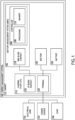
- FIG. 1 is a block diagram of an energy management system 100, in accordance with one or more examples of the present disclosure.
- the energy management system 100 includes a battery management system (BMS) 102 connected to one or more batteries 104.
- BMS battery management system
- the energy management system 100 included any number or type of batteries 104 such as, but not limited to, lithium-ion, nickelcadmium, or lead acid.
- a battery 104 may be formed as a single unit or as multiple units connected in either series or parallel.
- a battery 104 may be formed as a rack of battery sub-units.
- the batteries 104 include components to perform various functions such as, but not limited to, monitoring, control, or communications.
- a battery 104 may include one or more sensors to monitor properties such as, but not limited to, charge, a charging state, a voltage, incoming or outgoing current, temperature, or predicted lifespan.
- a battery 104 may include charging circuitry to control charge/discharge rates, circuity to prevent over-voltage, over-current, or over-temperature conditions, or the like.
- the BMS 102 includes any type of battery management or control system known in the art and may perform a variety of operations.
- a BMS 102 includes one or more sensors configured and/or monitoring circuitry to monitor various aspects of any of the batteries 104 including, but not limited to, a charge, a charging state, a voltage, incoming or outgoing current, temperature, or predicted lifespan.
- the BMS 102 includes any type of sensor known in the art including, but not limited to, a current sensor, a voltage sensor, or a temperature sensor.
- the BMS 102 includes a controller 106 with one or more processors 108 configured to execute program instructions maintained on a memory 110
- the program instructions causes the processors 108 of the controller 106 to perform various functions directly or indirectly (e.g., by generating control signals). As an illustration, the program instructions cause the processors 108 to perform functions associated with the monitoring and/or management of one or more connected batteries 104.
- the controller 106 may perform various control functions such as, but not limited to, load balancing between batteries 104, charging control, over-voltage protection, over-current protection, or over-heating protection.
- the BMS 102 includes communications circuitry to communicate with additional systems, such as, but not limited to, an external control system, an additional BMS 102, the batteries 104, or the like.
- the BMS 102 may receive power supply data associated with available power or predicted power availability, load data associated with current or predicted load conditions, data from any of the batteries 104, or the like.
- the one or more processors 108 of a controller 106 includes any processing element known in the art.
- the one or more processors 108 includes any microprocessor-type device configured to execute algorithms and/or instructions.
- the processors 108 may include one or more central processing units (CPUs), graphical processing units (GPUs), digital signal processors (DSPs), field-programmable gate arrays (FPGAs), or application-specific integrated circuits (ASICs).
- CPUs central processing units
- GPUs graphical processing units
- DSPs digital signal processors
- FPGAs field-programmable gate arrays
- ASICs application-specific integrated circuits
- the memory 110 includes any storage medium known in the art suitable for storing program instructions executable by the associated one or more processors 108.
- the memory 110 may include a non-transitory memory medium.
- the memory 110 may include, but is not limited to, a read-only memory (ROM), a random-access memory (RAM), a magnetic or optical memory device (e.g., disk), a magnetic tape, a solid-state drive, and the like.
- the energy management system 100 includes one or more cabinets 112 to secure and/or house various components such as, but not limited to, the BMS 102 or any of the batteries 104.
- a cabinet 112 may be a rack system including various openings, platforms, rails, guides, or the like suitable for housing the various components.
- a cabinet 112 may further include components suitable for providing electrical connections with or between any installed components.
- the cabinet 112 includes a landing plate (LP) 114 providing a blind mate connection to a BMS 102 installed within the cabinet 112.
- LP landing plate
- an LP 114 may include at least one LP blind contact 116 configured to provide a blind mate connection with a corresponding BMS blind contact 118 located on the BMS 102.
- an LP blind contact 116 and a BMS blind contact 118 may together form a blind mate connector.
- the LP 114 and the BMS 102 may include any number of LP blind contacts 116 and BMS blind contacts 118, respectively, to provide any number or type of electrical connections.
- the LP blind contacts 116 and the BMS blind contacts 118 may provide any number of hot connections, neutral connections, ground connections, or the like. Further, the LP blind contacts 116 and the BMS blind contacts 118 may provide any combination of direct current (DC) power transfer, alternating current (AC) power transfer, or communications in uni-directional or bi-directional configurations.
- DC direct current
- AC alternating current
- the LP 114 further includes one or more terminals 120, at least some of which are electrically connected to the LP blind contacts 116.
- the terminals 120 provide electrical connections between various components within the energy management system 100 and/or to external systems.
- the terminals 120 may provide connections to the batteries 104 to be managed by the BMS 102.
- the terminals 120 may provide connections to external systems such as, but not limited to, an electrical grid 122, a power source 124 (e.g., solar energy source, a wind energy source, or the like), or a load 126.
- the energy management system 100 provides a variety of different functions, which may be managed at least in part by the BMS 102.
- the energy management system 100 operates as an uninterruptible power supply (UPS).
- the load 126 may be powered by any combination of a grid 122 or a power source 124 under typical conditions, but may be powered by the batteries 104 when the grid 122 and/or the power source 124 have insufficient power supply. Further, the batteries 104 may be charged by the grid 122 and/or the power source 124 and/or may provide power back to the grid 122 and/or the power source 124.
- connections between the LP 114, the BMS 102, and the batteries 104 are described in greater detail, in accordance with one or more examples of the present disclosure.
- FIGS. 2A-2C depict installation of a BMS 102 into a cabinet 112 to establish a blind mate electrical connection, in accordance with one or more examples of the present disclosure.
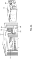
- FIG. 2A is a perspective view of a cabinet 112 and a BMS 102 prior to insertion of the BMS 102 into the cabinet 112, in accordance with one or more examples of the present disclosure.
- FIG. 2B is a perspective view of a cabinet 112 and a BMS 102 after insertion of the BMS 102 into the cabinet 112 in which a blind mate electrical connection is established, in accordance with one or more examples of the present disclosure.
- FIG. 2C is a perspective cross-sectional view of the BMS 102 and the LP 114 illustrating the blind mate electrical connection, in accordance with one or more examples of the present disclosure.
- a BMS 102 is shown with a housing 202 sized to fit within an opening 204 of the cabinet 112. Further, the cabinet 112 may include various features to receive and/or position the BMS 102 within the such as, but not limited to, a platform 206, guides 208, or the like.
- FIGS. 2A-2C further depict a LP 114 in a rear portion of the opening 204 formed as a mechanically rigid material suitable for supporting LP blind contacts 116 for connecting to the BMS 102 and terminals 120 for connecting to additional components such as, but not limited to, the batteries 104.
- the LP 114 is formed from a non-conductive material. In this way, the terminals 120 and the LP blind contacts 116 may be electrically connected via conductors.
- the LP 114 is formed from a conductive material. In this configuration, various non-conductive materials may be used to insulate any electrical connections.
- the blind mate connectors formed from the LP blind contacts 116 and the BMS blind contacts 118 may be formed as any type of blind mate connector known in the art.
- many blind mate connectors include a male connector and a female connector, which may connect through a sliding interlock, a snapping interlock, or the like, though this is not a requirement.
- a blind mate connector may be configured to provide a single electrical connection or multiple electrical connections. In the case of multiple electrical connections, these connections may be made simultaneously or sequentially.
- a male portion of a blind mate connector may include multiple contacts (e.g., pins, busbars, or the like) of different lengths to provide sequential connections.
- a female portion of a blind mate connector may include multiple contacts recessed at different depths to provide sequential connections. Further, any of the various contacts may be shielded or unshielded.
- any of the LP blind contacts 116 or the BMS blind contacts 118 may be male or female. Further, the BMS 102 and the LP 114 may utilize blind mate connectors of a single design or multiple designs.
- FIGS. 2A-2C depict a configuration in which the LP blind contacts 116 are formed as busbars (e.g., male connectors) while the BMS blind contacts 118 are formed as clamps (e.g., female connectors).
- the busbars are metal busbars.
- the busbars may slide into and out of the clamps to establish an electrical connection and may slide out of the clamps for disconnection.
- the clamps may include or be formed from a spring to provide a stable electrical connection while still facilitating coupling and decoupling.
- Alignment between the LP blind contacts 116 and the BMS blind contact 118 during insertion of the BMS 102 into the cabinet 112 may be achieved through a variety of techniques.
- the LP 114 and/or the BMS 102 include keyed or guiding features near any of the associated contacts to ensure alignment at locations near any of the contacts.
- the guides 208 and/or the platform 206 of the cabinet 112 in FIGS. 2A-2C may be guiding features that position the BMS 102 with respect to the LP 114 with sufficient accuracy to provide a reliable connection between the LP blind contacts 116 and the BMS blind contacts 118.
- keyed and/or guiding features only allow insertion of the BMS 102 in a selected orientation that ensures alignment of the LP blind contacts 116 and the BMS blind contact 118.
- the shape of the opening 204 itself may provide sufficient alignment of the LP blind contacts 116 and the BMS blind contact 118.
- this is merely and illustration and should not be interpreted as limiting the scope of the present disclosure.
- the electrical connection between the BMS 102 and the LP 114 is secured using any suitable technique.
- the BMS 102 is mechanically secured to the cabinet 112 in a way sufficient to prevent unintentional disconnections between the LP blind contacts 116 and the BMS blind contacts 118.
- FIG. 2A depicts a latch 210 on the cabinet 112 to mechanically secure the BMS 102.
- the BMS 102 and/or the LP 114 includes components to snap together when the BMS 102 is fully installed such that the BMS 102 may only be removed by applying a force sufficient to unsnap these components.
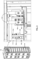
- FIG. 3 is a perspective view of a backside of the cabinet illustrating terminals 120 for connecting the LP 114 to additional components, in accordance with one or more examples of the present disclosure.
- the terminals 120 may provide electrical connections to the batteries 104, a grid 122, a power source 124, or the like as depicted in FIG. 1 .
- FIG. 3 depicts a first set of terminals 120a connected to a first set of power cables 302 providing to connections to batteries 104 within the cabinet 112.
- FIG. 3 further depicts a second set of terminals 120b connected to a second set of cables 304 providing connections to components outside the cabinet 112 (e.g., the grid 122 and/or power source 124 as depicted in FIG. 1 ).
- the terminals 120 include any sort of electrical connectors known in the art.
- a terminal 120 is a blind connector suitable for providing a blind mate connection with another component.
- the batteries 104 may be designed to provide blind mate connections to the LP 114 in a manner similar to that described for the BMS 102.
- a terminal 120 is a typical connector providing a mechanically-fastened connection.
- FIG. 3 illustrates a configuration in which the terminal 120 includes a threaded bolt onto which a conductive plate 306 from a cable 304 may be secured with a nut. Such a configuration may provide a convenient connection to widely available cables, which may increase ease of use and reduce cost and complexity.
- any of the terminals 120 may utilize any type of electrical connection technique known in the art.
- the terminals 120 may include any combination of male or female connector components.
- a cabinet 112 may include any number of LPs 114 located at any location suitable for making an electrical connection with the BMS 102.
- a cabinet 112 may include an LP 114 on a side of the opening 204 to make blind mate connections with BMS blind contacts 118 on a corresponding side of the housing 202The BMS blind contacts 118 are attached to the housing 202.
- various terminals 120 may be located at any location of the LP 114 and thus may be located on the same face as the LP blind contacts 116 or an opposite face from the LP blind contacts 116 (e.g., as depicted in FIGS. 2A-3 ).
- any two components herein combined to achieve a particular functionality can be seen as “associated with” each other such that the desired functionality is achieved, irrespective of architectures or intermedial components.
- any two components so associated can also be viewed as being “connected” or “coupled” to each other to achieve the desired functionality, and any two components capable of being so associated can also be viewed as being “couplable” to each other to achieve the desired functionality.
- Specific examples of couplable include but are not limited to physically interactable and/or physically interacting components and/or wirelessly interactable and/or wirelessly interacting components and/or logically interactable and/or logically interacting components.
Landscapes
- Engineering & Computer Science (AREA)
- General Chemical & Material Sciences (AREA)
- Electrochemistry (AREA)
- Chemical Kinetics & Catalysis (AREA)
- Chemical & Material Sciences (AREA)
- Theoretical Computer Science (AREA)
- Microelectronics & Electronic Packaging (AREA)
- Power Engineering (AREA)
- General Engineering & Computer Science (AREA)
- General Physics & Mathematics (AREA)
- Physics & Mathematics (AREA)
- Human Computer Interaction (AREA)
- Computer Hardware Design (AREA)
- Manufacturing & Machinery (AREA)
- Charge And Discharge Circuits For Batteries Or The Like (AREA)
- Battery Mounting, Suspending (AREA)
Abstract
Description
- The present disclosure relates generally to a battery management system (BMS) and, more particularly, to connections between a BMS system and a cabinet including one or more batteries.
- Market pressure continues to demand increased power and energy density for uninterruptible power supply (UPS) backup batteries, which in turn drives a demand for miniaturization of ancillary items such as the battery management system (BMS) and cable routing areas inside a cabinet. At the same time, it may be desirable to improve field operability of a BMS or other components. There is therefore a need to develop systems and methods to address these needs.
- In a first aspect of the present disclosure, the techniques described herein relate to a system including a cabinet including an opening configured to accept a battery management system (BMS) for controlling one or more batteries; and a landing plate (LP) including one or more LP blind contacts configured to mate with one or more BMS blind contacts located on the BMS to establish one or more electrical connections between the BMS and one or more electrical conductors in the cabinet when the BMS is inserted into the opening.
- In an example, the techniques described herein relate to a system, where the one or more electrical conductors are configured to connect to the one or more batteries, where the one or more batteries and the BMS are electrically connected when the BMS is inserted in the opening.
- In an example, the techniques described herein relate to a system, where the LP further includes one or more terminals, where at least one of the one or more terminals is electrically connected to the one or more electrical conductors.
- In an example, the techniques described herein relate to a system, where at least one of the one or more terminals is configured to provide electrical connections to an external system.
- In an example, the techniques described herein relate to a system, where the external system includes at least one of a load, an electrical grid, or a power source.
- In an example, the techniques described herein relate to a system, where the one or more terminals are on an opposite side of the LP than at least one of the one or more LP blind contacts.
- In an example, the techniques described herein relate to a system, where the system includes an uninterruptible power supply (UPS).
- In an example, the techniques described herein relate to a system, where the one or more LP blind contacts and the one or more corresponding BMS blind contacts form one or more blind mate connectors.
- In an example, the techniques described herein relate to a system, where the one or more LP blind contacts include one or more male connectors, where the one or more BMS blind contacts include one or more female connectors.
- In an example, the techniques described herein relate to a system, where at least one of the one or more male connectors includes a metal busbar, where a corresponding one of the one or more female connectors includes a clamp.
- In an example, the techniques described herein relate to a system, where the one or more LP blind contacts include one or more female connectors, where the one or more BMS blind contacts include one or more male connectors.
- In an example, the techniques described herein relate to a system, where at least one of the one or more male connectors includes a metal busbar, where a corresponding one of the one or more female connectors includes a clamp.
- In an example, the techniques described herein relate to a system, where at least one of the BMS or the cabinet includes one or more guiding features to align the one or more BMS blind contacts to the one or more LP blind contacts when the BMS is inserted into the opening of the cabinet.
- In an example, the techniques described herein relate to a battery management system (BMS) including a housing; and one or more BMS blind contacts attached to the housing configured to mate with one or more landing pate (LP) blind contacts located on an LP of a cabinet to establish one or more electrical connections between the BMS and one or more electrical conductors in the cabinet when the BMS is inserted into an opening of the cabinet.
- In an example, the techniques described herein relate to a BMS, where the one or more electrical conductors are configured to connect to one or more batteries, where the one or more batteries and the BMS are electrically connected when the BMS is inserted in the opening.
- In an example, the techniques described herein relate to a BMS, where the one or more LP blind contacts and the corresponding BMS blind contacts form one or more blind mate connectors.
- In an example, the techniques described herein relate to a BMS, where the one or more LP blind contacts include one or more male connectors, where the one or more BMS blind contacts include one or more female connectors.
- In an example, the techniques described herein relate to a BMS, where the one or more LP blind contacts include one or more female connectors, where the one or more BMS blind contacts include one or more male connectors.
- In an example, the techniques described herein relate to a BMS, where at least one of the BMS or the cabinet includes one or more guiding features to align the one or more BMS blind contacts to the one or more LP blind contacts when the BMS is inserted into the opening of the cabinet.
- In an example, the techniques described herein relate to a BMS, further including a controller including one or more processors configured to execute program instructions stored in a memory device, where the program instructions are configured to cause the one or more processors to at least one of monitor or control the one or more batteries.
- It is to be understood that both the foregoing general description and the following detailed description are exemplary and explanatory only and are not necessarily restrictive of the invention as claimed. The accompanying drawings, which are incorporated in and constitute a part of the specification, illustrate examples of the invention and together with the general description, serve to explain the principles of the invention.
- The numerous advantages of the disclosure may be better understood by those skilled in the art by reference to the accompanying figures.
-
FIG. 1 is a block diagram of an energy management system, in accordance with one or more examples of the present disclosure. -
FIG. 2A is a perspective view of a cabinet and a battery management system (BMS) prior to insertion of the BMS into the cabinet, in accordance with one or more examples of the present disclosure. -
FIG. 2B is a perspective view of a cabinet and a BMS after insertion of the BMS into the cabinet in which a blind mate electrical connection is established, in accordance with one or more examples of the present disclosure. -
FIG. 2C is a perspective cross-sectional view of the BMS and a landing plate (LP) illustrating the blind mate electrical connection, in accordance with one or more examples of the present disclosure. -
FIG. 3 is a perspective view of a backside of the cabinet illustrating terminals for connecting the LP to additional components, in accordance with one or more examples of the present disclosure. - Reference will now be made in detail to the subject matter disclosed, which is illustrated in the accompanying drawings. The present disclosure has been particularly shown and described with respect to certain examples and specific features thereof. The examples set forth herein are taken to be illustrative rather than limiting. It should be readily apparent to those of ordinary skill in the art that various changes and modifications in form and detail may be made without departing from the spirit and scope of the disclosure.
- Examples of the present disclosure are directed to systems and methods providing a blind mate electrical connection between a battery management system (BMS) and a cabinet, which may secure the BMS as well as batteries to be connected to the BMS.
- In some examples, an energy management system includes a cabinet with an opening to receive (e.g., accept) a BMS and a landing plate configured to receive the BMS when inserted into the opening. The landing plate (LP) and the BMS may be electrically connected using one or more blind mate couplers when the BMS is inserted into the opening. For example, the LP may include LP blind contacts configured to couple with corresponding BMS blind contacts on a BMS when the BMS is inserted within a cabinet. In this way, an LP blind contact and a BMS blind contact may form a blind mate coupler suitable for providing a blind mate electrical connection. The landing plate may further include one or more terminals to provide electrical connections to one or more batteries to be managed by the BMS.
- As used herein, a blind mate connection or blind mate coupling refers to electrical coupling and decoupling between an enclosure (here, a cabinet) and an insertable module (here, a BMS) upon insertion and removal of the module, respectively, without the use of mechanical fasteners specific to the electrical connection. In contrast, typical electrical connectors include or require a mechanical fastener to secure an electrical connection such as, but not limited to, a threaded connector, a nut-and-bolt connector, a retention tab (e.g., a locking tab), or the like. In a blind mate connection, the electrical connection may be secured if necessary by fastening the module to the enclosure.
- The systems and methods disclosed herein may provide various benefits for an energy management system. For example, a blind mate electrical connection between a BMS and a cabinet may facilitate easy removal of the BMS as necessary for repairs, replacement, or the like. As another example, a landing plate within the cabinet providing both LP blind contacts for the blind mate connection to the BMS as well as terminals for electrical connections to one or more batteries may facilitate convenient power connections for the batteries in a compact form factor that minimizes volume, part count, and cost.
- As an illustration, typical systems utilize traditional mechanically-fastened electrical connects between the BMS and batteries, which often requires a separate conduit box to operate as a coupler between the BMS and the batteries. Such a configuration further requires a design that provides access to such electrical connections to the BMS and requires effort during servicing to disconnect and then reconnect the BMS. In contrast, the systems and methods disclosed herein provide a robust landing area for the batteries, which may conveniently receive large cables or busbars from a rigid conduit in a space-efficient manner, and which may also facilitate easy servicing of the BMS through the blind mate connection. As a result, the systems and methods disclosed herein may provide high energy and power density (e.g., performance per unit of cost) in a small form factor as well as convenient installation and servicing of all components.
- Referring now to
FIGS. 1-3 , systems and methods for blind mate connections to a BMS are described in greater detail, in accordance with one or more examples of the present disclosure. -
FIG. 1 is a block diagram of anenergy management system 100, in accordance with one or more examples of the present disclosure. - The
energy management system 100 includes a battery management system (BMS) 102 connected to one ormore batteries 104. Theenergy management system 100 included any number or type ofbatteries 104 such as, but not limited to, lithium-ion, nickelcadmium, or lead acid. Further, abattery 104 may be formed as a single unit or as multiple units connected in either series or parallel. For example, abattery 104 may be formed as a rack of battery sub-units. - The
batteries 104 include components to perform various functions such as, but not limited to, monitoring, control, or communications. For example, abattery 104 may include one or more sensors to monitor properties such as, but not limited to, charge, a charging state, a voltage, incoming or outgoing current, temperature, or predicted lifespan. As another example, abattery 104 may include charging circuitry to control charge/discharge rates, circuity to prevent over-voltage, over-current, or over-temperature conditions, or the like. - The
BMS 102 includes any type of battery management or control system known in the art and may perform a variety of operations. ABMS 102 includes one or more sensors configured and/or monitoring circuitry to monitor various aspects of any of thebatteries 104 including, but not limited to, a charge, a charging state, a voltage, incoming or outgoing current, temperature, or predicted lifespan. TheBMS 102 includes any type of sensor known in the art including, but not limited to, a current sensor, a voltage sensor, or a temperature sensor. TheBMS 102 includes acontroller 106 with one ormore processors 108 configured to execute program instructions maintained on amemory 110 - (e.g., memory medium). The program instructions causes the
processors 108 of thecontroller 106 to perform various functions directly or indirectly (e.g., by generating control signals). As an illustration, the program instructions cause theprocessors 108 to perform functions associated with the monitoring and/or management of one or moreconnected batteries 104. For example, thecontroller 106 may perform various control functions such as, but not limited to, load balancing betweenbatteries 104, charging control, over-voltage protection, over-current protection, or over-heating protection. TheBMS 102 includes communications circuitry to communicate with additional systems, such as, but not limited to, an external control system, anadditional BMS 102, thebatteries 104, or the like. For example, theBMS 102 may receive power supply data associated with available power or predicted power availability, load data associated with current or predicted load conditions, data from any of thebatteries 104, or the like. - The one or
more processors 108 of acontroller 106 includes any processing element known in the art. In this sense, the one ormore processors 108 includes any microprocessor-type device configured to execute algorithms and/or instructions. For example, theprocessors 108 may include one or more central processing units (CPUs), graphical processing units (GPUs), digital signal processors (DSPs), field-programmable gate arrays (FPGAs), or application-specific integrated circuits (ASICs). - The
memory 110 includes any storage medium known in the art suitable for storing program instructions executable by the associated one ormore processors 108. For example, thememory 110 may include a non-transitory memory medium. By way of another example, thememory 110 may include, but is not limited to, a read-only memory (ROM), a random-access memory (RAM), a magnetic or optical memory device (e.g., disk), a magnetic tape, a solid-state drive, and the like. - The
energy management system 100 includes one ormore cabinets 112 to secure and/or house various components such as, but not limited to, theBMS 102 or any of thebatteries 104. For example, acabinet 112 may be a rack system including various openings, platforms, rails, guides, or the like suitable for housing the various components. As will be described in greater detail below, acabinet 112 may further include components suitable for providing electrical connections with or between any installed components. - The
cabinet 112 includes a landing plate (LP) 114 providing a blind mate connection to aBMS 102 installed within thecabinet 112. For example, anLP 114 may include at least oneLP blind contact 116 configured to provide a blind mate connection with a corresponding BMSblind contact 118 located on theBMS 102. In this way, an LPblind contact 116 and a BMSblind contact 118 may together form a blind mate connector. In a general sense, theLP 114 and theBMS 102 may include any number of LPblind contacts 116 and BMSblind contacts 118, respectively, to provide any number or type of electrical connections. For example, the LPblind contacts 116 and the BMSblind contacts 118 may provide any number of hot connections, neutral connections, ground connections, or the like. Further, the LPblind contacts 116 and the BMSblind contacts 118 may provide any combination of direct current (DC) power transfer, alternating current (AC) power transfer, or communications in uni-directional or bi-directional configurations. - The
LP 114 further includes one ormore terminals 120, at least some of which are electrically connected to the LPblind contacts 116. In a general sense, theterminals 120 provide electrical connections between various components within theenergy management system 100 and/or to external systems. For example, theterminals 120 may provide connections to thebatteries 104 to be managed by theBMS 102. As another example, theterminals 120 may provide connections to external systems such as, but not limited to, anelectrical grid 122, a power source 124 (e.g., solar energy source, a wind energy source, or the like), or aload 126. - The
energy management system 100 provides a variety of different functions, which may be managed at least in part by the BMS 102.,Theenergy management system 100 operates as an uninterruptible power supply (UPS). In this configuration, theload 126 may be powered by any combination of agrid 122 or apower source 124 under typical conditions, but may be powered by thebatteries 104 when thegrid 122 and/or thepower source 124 have insufficient power supply. Further, thebatteries 104 may be charged by thegrid 122 and/or thepower source 124 and/or may provide power back to thegrid 122 and/or thepower source 124. - Referring now to
FIGS. 2A-3 , connections between theLP 114, theBMS 102, and thebatteries 104 are described in greater detail, in accordance with one or more examples of the present disclosure. -
FIGS. 2A-2C depict installation of aBMS 102 into acabinet 112 to establish a blind mate electrical connection, in accordance with one or more examples of the present disclosure.FIG. 2A is a perspective view of acabinet 112 and aBMS 102 prior to insertion of theBMS 102 into thecabinet 112, in accordance with one or more examples of the present disclosure.FIG. 2B is a perspective view of acabinet 112 and aBMS 102 after insertion of theBMS 102 into thecabinet 112 in which a blind mate electrical connection is established, in accordance with one or more examples of the present disclosure.FIG. 2C is a perspective cross-sectional view of theBMS 102 and theLP 114 illustrating the blind mate electrical connection, in accordance with one or more examples of the present disclosure. - In
FIGS. 2A-2C , aBMS 102 is shown with ahousing 202 sized to fit within anopening 204 of thecabinet 112. Further, thecabinet 112 may include various features to receive and/or position theBMS 102 within the such as, but not limited to, aplatform 206, guides 208, or the like. -
FIGS. 2A-2C further depict aLP 114 in a rear portion of theopening 204 formed as a mechanically rigid material suitable for supporting LPblind contacts 116 for connecting to theBMS 102 andterminals 120 for connecting to additional components such as, but not limited to, thebatteries 104. TheLP 114 is formed from a non-conductive material. In this way, theterminals 120 and the LPblind contacts 116 may be electrically connected via conductors. In some examples, theLP 114 is formed from a conductive material. In this configuration, various non-conductive materials may be used to insulate any electrical connections. - The blind mate connectors formed from the LP
blind contacts 116 and the BMSblind contacts 118 may be formed as any type of blind mate connector known in the art. For example, many blind mate connectors include a male connector and a female connector, which may connect through a sliding interlock, a snapping interlock, or the like, though this is not a requirement. A blind mate connector may be configured to provide a single electrical connection or multiple electrical connections. In the case of multiple electrical connections, these connections may be made simultaneously or sequentially. As an illustration, a male portion of a blind mate connector may include multiple contacts (e.g., pins, busbars, or the like) of different lengths to provide sequential connections. As another illustration, a female portion of a blind mate connector may include multiple contacts recessed at different depths to provide sequential connections. Further, any of the various contacts may be shielded or unshielded. - It is contemplated herein that any of the LP
blind contacts 116 or the BMSblind contacts 118 may be male or female. Further, theBMS 102 and theLP 114 may utilize blind mate connectors of a single design or multiple designs. - As an illustration,
FIGS. 2A-2C depict a configuration in which the LPblind contacts 116 are formed as busbars (e.g., male connectors) while the BMSblind contacts 118 are formed as clamps (e.g., female connectors). The busbars are metal busbars. In this configuration, the busbars may slide into and out of the clamps to establish an electrical connection and may slide out of the clamps for disconnection. Further, the clamps may include or be formed from a spring to provide a stable electrical connection while still facilitating coupling and decoupling. - Alignment between the LP
blind contacts 116 and the BMSblind contact 118 during insertion of theBMS 102 into thecabinet 112 may be achieved through a variety of techniques. TheLP 114 and/or theBMS 102 include keyed or guiding features near any of the associated contacts to ensure alignment at locations near any of the contacts. For example, theguides 208 and/or theplatform 206 of thecabinet 112 inFIGS. 2A-2C may be guiding features that position theBMS 102 with respect to theLP 114 with sufficient accuracy to provide a reliable connection between the LPblind contacts 116 and the BMSblind contacts 118. In some cases, keyed and/or guiding features only allow insertion of theBMS 102 in a selected orientation that ensures alignment of the LPblind contacts 116 and the BMSblind contact 118. As another example, the shape of theopening 204 itself may provide sufficient alignment of the LPblind contacts 116 and the BMSblind contact 118. However, this is merely and illustration and should not be interpreted as limiting the scope of the present disclosure. - The electrical connection between the
BMS 102 and theLP 114 is secured using any suitable technique. TheBMS 102 is mechanically secured to thecabinet 112 in a way sufficient to prevent unintentional disconnections between the LPblind contacts 116 and the BMSblind contacts 118. For example,FIG. 2A depicts alatch 210 on thecabinet 112 to mechanically secure theBMS 102. In some examples, theBMS 102 and/or theLP 114 includes components to snap together when theBMS 102 is fully installed such that theBMS 102 may only be removed by applying a force sufficient to unsnap these components. -
FIG. 3 is a perspective view of a backside of thecabinet illustrating terminals 120 for connecting theLP 114 to additional components, in accordance with one or more examples of the present disclosure. For example, theterminals 120 may provide electrical connections to thebatteries 104, agrid 122, apower source 124, or the like as depicted inFIG. 1 . - As an illustration,
FIG. 3 depicts a first set ofterminals 120a connected to a first set ofpower cables 302 providing to connections tobatteries 104 within thecabinet 112.FIG. 3 further depicts a second set ofterminals 120b connected to a second set ofcables 304 providing connections to components outside the cabinet 112 (e.g., thegrid 122 and/orpower source 124 as depicted inFIG. 1 ). - The
terminals 120 include any sort of electrical connectors known in the art. In some examples, a terminal 120 is a blind connector suitable for providing a blind mate connection with another component. For example, thebatteries 104 may be designed to provide blind mate connections to theLP 114 in a manner similar to that described for theBMS 102. A terminal 120 is a typical connector providing a mechanically-fastened connection. For example,FIG. 3 illustrates a configuration in which the terminal 120 includes a threaded bolt onto which aconductive plate 306 from acable 304 may be secured with a nut. Such a configuration may provide a convenient connection to widely available cables, which may increase ease of use and reduce cost and complexity. However, it is to be understood that any of theterminals 120 may utilize any type of electrical connection technique known in the art. Further, theterminals 120 may include any combination of male or female connector components. - Referring generally to
FIGS. 2A-3 , it is to be understood thatFIGS. 2A-3 are provided solely for illustrative purposes and should not be interpreted as limiting. For example, acabinet 112 may include any number ofLPs 114 located at any location suitable for making an electrical connection with theBMS 102. For example, acabinet 112 may include anLP 114 on a side of theopening 204 to make blind mate connections with BMSblind contacts 118 on a corresponding side of the housing 202The BMSblind contacts 118 are attached to thehousing 202. As another example,various terminals 120 may be located at any location of theLP 114 and thus may be located on the same face as the LPblind contacts 116 or an opposite face from the LP blind contacts 116 (e.g., as depicted inFIGS. 2A-3 ). - The herein described subject matter sometimes illustrates different components contained within, or connected with, other components. It is to be understood that such depicted architectures are merely exemplary, and that in fact many other architectures can be implemented which achieve the same functionality. In a conceptual sense, any arrangement of components to achieve the same functionality is effectively "associated" such that the desired functionality is achieved. Hence, any two components herein combined to achieve a particular functionality can be seen as "associated with" each other such that the desired functionality is achieved, irrespective of architectures or intermedial components. Likewise, any two components so associated can also be viewed as being "connected" or "coupled" to each other to achieve the desired functionality, and any two components capable of being so associated can also be viewed as being "couplable" to each other to achieve the desired functionality. Specific examples of couplable include but are not limited to physically interactable and/or physically interacting components and/or wirelessly interactable and/or wirelessly interacting components and/or logically interactable and/or logically interacting components.
- It is believed that the present disclosure and many of its attendant advantages will be understood by the foregoing description, and it will be apparent that various changes may be made in the form, construction, and arrangement of the components without departing from the disclosed subject matter or without sacrificing all of its material advantages. The form described is merely explanatory, and it is the intention of the following claims to encompass and include such changes. Furthermore, it is to be understood that the invention is defined by the appended claims.
Claims (15)
- A system comprising:a cabinet including an opening configured to accept a battery management system (BMS) for controlling one or more batteries; anda landing plate (LP) including one or more LP blind contacts configured to mate with one or more BMS blind contacts located on the BMS to establish one or more electrical connections between the BMS and one or more electrical conductors in the cabinet when the BMS is inserted into the opening.
- The system of claim 1, wherein the one or more electrical conductors are configured to connect to the one or more batteries, wherein the one or more batteries and the BMS are electrically connected when the BMS is inserted in the opening.
- The system of claim 1, wherein the LP further includes one or more terminals, wherein at least one of the one or more terminals is electrically connected to the one or more electrical conductors.
- The system of claim 3, wherein at least one of the one or more terminals is configured to provide electrical connections to an external system, and preferably, wherein the external system comprises:
at least one of a load, an electrical grid, or a power source. - The system of claim 3, wherein the one or more terminals are on an opposite side of the LP than at least one of the one or more LP blind contacts.
- The system of claim 1, wherein the system comprises an uninterruptible power supply (UPS).
- The system of claim 1, wherein the one or more LP blind contacts and the one or more BMS blind contacts form one or more blind mate connectors, and/or wherein the one or more LP blind contacts include one or more male connectors, wherein the one or more BMS blind contacts include one or more female connectors, and wherein preferably a corresponding one of the one or more female connectors comprises a clamp, and/or wherein the one or more LP blind contacts include one or more female connectors, wherein the one or more BMS blind contacts include one or more male connectors, and wherein preferably . at least one of the one or more male connectors comprises a metal busbar, wherein a corresponding one of the one or more female connectors comprises a clamp.
- The system of claim 1, wherein at least one of the BMS or the cabinet includes one or more guiding features to align the one or more BMS blind contacts to the one or more LP blind contacts when the BMS is inserted into the opening of the cabinet.
- A battery management system (BMS) comprising:a housing; andone or more BMS blind contacts attached to the housing configured to mate with one or more landing plate (LP) blind contacts located on an LP of a cabinet to establish one or more electrical connections between the BMS and one or more electrical conductors in the cabinet when the BMS is inserted into an opening of the cabinet.
- The BMS of claim 9, wherein the one or more electrical conductors are configured to connect to one or more batteries, wherein the one or more batteries and the BMS are electrically connected when the BMS is inserted in the opening.
- The BMS of claim 9, wherein the one or more LP blind contacts and the one or more BMS blind contacts form one or more blind mate connectors.
- The BMS of claim 9, wherein the one or more LP blind contacts include one or more male connectors, wherein the one or more BMS blind contacts include one or more female connectors.
- The BMS of claim 9, wherein the one or more LP blind contacts include one or more female connectors, wherein the one or more BMS blind contacts include one or more male connectors.
- The BMS of claim 9, wherein at least one of the BMS or the cabinet includes one or more guiding features to align the one or more BMS blind contacts to the one or more LP blind contacts when the BMS is inserted into the opening of the cabinet.
- The BMS of claim 9, further comprising:
a controller including one or more processors configured to execute program instructions stored in a memory device, wherein the program instructions are configured to cause the one or more processors to at least one of monitor or control the one or more batteries.
Applications Claiming Priority (2)
| Application Number | Priority Date | Filing Date | Title |
|---|---|---|---|
| US202363469725P | 2023-05-30 | 2023-05-30 | |
| US18/672,357 US20240405478A1 (en) | 2023-05-30 | 2024-05-23 | Battery cabinet with blind mate connectors |
Publications (2)
| Publication Number | Publication Date |
|---|---|
| EP4471932A2 true EP4471932A2 (en) | 2024-12-04 |
| EP4471932A3 EP4471932A3 (en) | 2025-03-19 |
Family
ID=91334900
Family Applications (1)
| Application Number | Title | Priority Date | Filing Date |
|---|---|---|---|
| EP24178998.1A Pending EP4471932A3 (en) | 2023-05-30 | 2024-05-30 | Battery cabinet with blind mate connectors |
Country Status (2)
| Country | Link |
|---|---|
| US (1) | US20240405478A1 (en) |
| EP (1) | EP4471932A3 (en) |
Families Citing this family (1)
| Publication number | Priority date | Publication date | Assignee | Title |
|---|---|---|---|---|
| USD1081601S1 (en) * | 2023-10-26 | 2025-07-01 | Yanmin Lin | DC control hub |
Family Cites Families (8)
| Publication number | Priority date | Publication date | Assignee | Title |
|---|---|---|---|---|
| US5640302A (en) * | 1992-06-29 | 1997-06-17 | Elonex Ip Holdings | Modular portable computer |
| AU2001241559A1 (en) * | 2000-02-18 | 2001-08-27 | Liebert Corporation | Modular uninterruptible power supply |
| CN103563210B (en) * | 2011-05-31 | 2017-03-22 | 株式会社Lg化学 | Power storage system including modular BMS connection structure and control method thereof |
| JP6058260B2 (en) * | 2011-10-28 | 2017-01-11 | 株式会社東芝 | Storage battery unit |
| US20150325818A1 (en) * | 2012-08-27 | 2015-11-12 | Nec Energy Devices, Ltd. | Power storage device |
| CN109786599B (en) * | 2018-12-29 | 2021-08-31 | 华为数字技术(苏州)有限公司 | an energy storage system |
| US11374366B2 (en) * | 2020-06-19 | 2022-06-28 | Lear Corporation | System and method for providing an electrical ground connection for a circuit assembly |
| CN112910079A (en) * | 2021-02-23 | 2021-06-04 | 艾普斯电源(天津)有限公司 | Expandable battery pack uninterrupted power supply comprehensive power distribution device |
-
2024
- 2024-05-23 US US18/672,357 patent/US20240405478A1/en active Pending
- 2024-05-30 EP EP24178998.1A patent/EP4471932A3/en active Pending
Also Published As
| Publication number | Publication date |
|---|---|
| US20240405478A1 (en) | 2024-12-05 |
| EP4471932A3 (en) | 2025-03-19 |
Similar Documents
| Publication | Publication Date | Title |
|---|---|---|
| CN111900502A (en) | Energy storage cabinet | |
| JP3516649B2 (en) | Storage battery storage cabinet and storage battery storage connection method | |
| EP3475997B1 (en) | Modular energy system for storing and releasing energy | |
| US7652397B2 (en) | Parallel-connected uninterruptible power supply system | |
| EP3893289B1 (en) | Energy storage system | |
| CN107925025B (en) | Battery packs and vehicles containing battery packs | |
| US20090053937A1 (en) | Stackable composite power connector | |
| US20200195026A1 (en) | Portable switching power supply with attachable battery pack and enclosure | |
| US20170187155A1 (en) | Wiring device with connector integrated into pcb substrate | |
| EP3235103B1 (en) | Modular uninterruptible power supply and power distribution system | |
| WO2023082761A1 (en) | Charging pile | |
| US20240405478A1 (en) | Battery cabinet with blind mate connectors | |
| CN119627348A (en) | Energy storage cabinet and energy storage system | |
| US20240072385A1 (en) | Power supply including a touch safe power supply core | |
| CN100477335C (en) | Battery and assembled rack battery system | |
| US20100248532A1 (en) | Electrical Coupler System and Method for Manufacture Thereof | |
| US20120025607A1 (en) | Power supply system for mounting to a rail | |
| CN217848566U (en) | Alternating current input module assembly, power supply system and cabinet | |
| CN119283630A (en) | Portable AC-DC power converter and vehicle power management device | |
| US8355236B2 (en) | Connector and power supply unit with safety mechanism | |
| US9692245B2 (en) | Battery management system and power connector | |
| US9627926B2 (en) | Backup power device, system and method of use | |
| KR20010041981A (en) | Uninterruptible power supply | |
| EP1376813A1 (en) | Electronic device, battery, and method for transporting current |
Legal Events
| Date | Code | Title | Description |
|---|---|---|---|
| PUAI | Public reference made under article 153(3) epc to a published international application that has entered the european phase |
Free format text: ORIGINAL CODE: 0009012 |
|
| STAA | Information on the status of an ep patent application or granted ep patent |
Free format text: STATUS: THE APPLICATION HAS BEEN PUBLISHED |
|
| AK | Designated contracting states |
Kind code of ref document: A2 Designated state(s): AL AT BE BG CH CY CZ DE DK EE ES FI FR GB GR HR HU IE IS IT LI LT LU LV MC ME MK MT NL NO PL PT RO RS SE SI SK SM TR |
|
| PUAL | Search report despatched |
Free format text: ORIGINAL CODE: 0009013 |
|
| AK | Designated contracting states |
Kind code of ref document: A3 Designated state(s): AL AT BE BG CH CY CZ DE DK EE ES FI FR GB GR HR HU IE IS IT LI LT LU LV MC ME MK MT NL NO PL PT RO RS SE SI SK SM TR |
|
| RIC1 | Information provided on ipc code assigned before grant |
Ipc: H02J 7/00 20060101ALI20250211BHEP Ipc: H01M 50/296 20210101ALI20250211BHEP Ipc: H01M 50/284 20210101ALI20250211BHEP Ipc: H01M 10/42 20060101AFI20250211BHEP |
|
| STAA | Information on the status of an ep patent application or granted ep patent |
Free format text: STATUS: REQUEST FOR EXAMINATION WAS MADE |
|
| 17P | Request for examination filed |
Effective date: 20250901 |