EP4471883A2 - Secondary battery and electronic apparatus - Google Patents
Secondary battery and electronic apparatus Download PDFInfo
- Publication number
- EP4471883A2 EP4471883A2 EP24179060.9A EP24179060A EP4471883A2 EP 4471883 A2 EP4471883 A2 EP 4471883A2 EP 24179060 A EP24179060 A EP 24179060A EP 4471883 A2 EP4471883 A2 EP 4471883A2
- Authority
- EP
- European Patent Office
- Prior art keywords
- negative electrode
- active material
- electrode active
- material layer
- secondary battery
- Prior art date
- Legal status (The legal status is an assumption and is not a legal conclusion. Google has not performed a legal analysis and makes no representation as to the accuracy of the status listed.)
- Pending
Links
- 239000007773 negative electrode material Substances 0.000 claims abstract description 175
- 229910052705 radium Inorganic materials 0.000 claims abstract description 4
- 238000010438 heat treatment Methods 0.000 claims description 48
- 239000011248 coating agent Substances 0.000 claims description 26
- 239000000203 mixture Substances 0.000 claims description 26
- 229910021383 artificial graphite Inorganic materials 0.000 claims description 20
- 238000010521 absorption reaction Methods 0.000 claims description 17
- 238000012360 testing method Methods 0.000 claims description 13
- 238000000034 method Methods 0.000 claims description 12
- 239000012298 atmosphere Substances 0.000 claims description 10
- 239000010426 asphalt Substances 0.000 claims description 9
- 229910021382 natural graphite Inorganic materials 0.000 claims description 8
- SECXISVLQFMRJM-UHFFFAOYSA-N N-Methylpyrrolidone Chemical compound CN1CCCC1=O SECXISVLQFMRJM-UHFFFAOYSA-N 0.000 claims description 6
- 238000002156 mixing Methods 0.000 claims description 6
- 239000010410 layer Substances 0.000 description 78
- 239000011149 active material Substances 0.000 description 36
- HBBGRARXTFLTSG-UHFFFAOYSA-N Lithium ion Chemical compound [Li+] HBBGRARXTFLTSG-UHFFFAOYSA-N 0.000 description 28
- 229910001416 lithium ion Inorganic materials 0.000 description 28
- 239000003792 electrolyte Substances 0.000 description 24
- 230000000052 comparative effect Effects 0.000 description 20
- 239000000843 powder Substances 0.000 description 20
- 239000003921 oil Substances 0.000 description 19
- 238000002360 preparation method Methods 0.000 description 17
- -1 polytetrafluoroethylene Polymers 0.000 description 16
- 238000006243 chemical reaction Methods 0.000 description 13
- 239000002245 particle Substances 0.000 description 10
- 239000002002 slurry Substances 0.000 description 10
- 238000000576 coating method Methods 0.000 description 9
- 238000013461 design Methods 0.000 description 8
- 239000000463 material Substances 0.000 description 8
- OKTJSMMVPCPJKN-UHFFFAOYSA-N Carbon Chemical compound [C] OKTJSMMVPCPJKN-UHFFFAOYSA-N 0.000 description 7
- PXHVJJICTQNCMI-UHFFFAOYSA-N Nickel Chemical compound [Ni] PXHVJJICTQNCMI-UHFFFAOYSA-N 0.000 description 7
- 239000002033 PVDF binder Substances 0.000 description 7
- 239000011230 binding agent Substances 0.000 description 7
- 238000009792 diffusion process Methods 0.000 description 7
- 239000007770 graphite material Substances 0.000 description 7
- 230000035515 penetration Effects 0.000 description 7
- 229920000642 polymer Polymers 0.000 description 7
- 229920002981 polyvinylidene fluoride Polymers 0.000 description 7
- 239000000126 substance Substances 0.000 description 7
- 239000001768 carboxy methyl cellulose Substances 0.000 description 6
- 150000002500 ions Chemical class 0.000 description 6
- 229910003002 lithium salt Inorganic materials 0.000 description 6
- 159000000002 lithium salts Chemical class 0.000 description 6
- 238000003825 pressing Methods 0.000 description 6
- RUOJZAUFBMNUDX-UHFFFAOYSA-N propylene carbonate Chemical compound CC1COC(=O)O1 RUOJZAUFBMNUDX-UHFFFAOYSA-N 0.000 description 6
- RYGMFSIKBFXOCR-UHFFFAOYSA-N Copper Chemical compound [Cu] RYGMFSIKBFXOCR-UHFFFAOYSA-N 0.000 description 5
- OIFBSDVPJOWBCH-UHFFFAOYSA-N Diethyl carbonate Chemical compound CCOC(=O)OCC OIFBSDVPJOWBCH-UHFFFAOYSA-N 0.000 description 5
- KMTRUDSVKNLOMY-UHFFFAOYSA-N Ethylene carbonate Chemical compound O=C1OCCO1 KMTRUDSVKNLOMY-UHFFFAOYSA-N 0.000 description 5
- 239000000654 additive Substances 0.000 description 5
- 230000000996 additive effect Effects 0.000 description 5
- 239000006258 conductive agent Substances 0.000 description 5
- JBTWLSYIZRCDFO-UHFFFAOYSA-N ethyl methyl carbonate Chemical compound CCOC(=O)OC JBTWLSYIZRCDFO-UHFFFAOYSA-N 0.000 description 5
- 239000011888 foil Substances 0.000 description 5
- 230000002427 irreversible effect Effects 0.000 description 5
- 239000012528 membrane Substances 0.000 description 5
- 239000003960 organic solvent Substances 0.000 description 5
- 229920000058 polyacrylate Polymers 0.000 description 5
- 230000035484 reaction time Effects 0.000 description 5
- 238000010998 test method Methods 0.000 description 5
- 239000004698 Polyethylene Substances 0.000 description 4
- 239000004743 Polypropylene Substances 0.000 description 4
- 230000009286 beneficial effect Effects 0.000 description 4
- 239000002131 composite material Substances 0.000 description 4
- 239000004020 conductor Substances 0.000 description 4
- 239000000470 constituent Substances 0.000 description 4
- 230000006837 decompression Effects 0.000 description 4
- IEJIGPNLZYLLBP-UHFFFAOYSA-N dimethyl carbonate Chemical compound COC(=O)OC IEJIGPNLZYLLBP-UHFFFAOYSA-N 0.000 description 4
- 239000007789 gas Substances 0.000 description 4
- 229910052744 lithium Inorganic materials 0.000 description 4
- 229910052751 metal Inorganic materials 0.000 description 4
- 239000002184 metal Substances 0.000 description 4
- 229920000573 polyethylene Polymers 0.000 description 4
- 229920001155 polypropylene Polymers 0.000 description 4
- 239000007774 positive electrode material Substances 0.000 description 4
- 238000012545 processing Methods 0.000 description 4
- 229920003048 styrene butadiene rubber Polymers 0.000 description 4
- 239000000758 substrate Substances 0.000 description 4
- SBLRHMKNNHXPHG-UHFFFAOYSA-N 4-fluoro-1,3-dioxolan-2-one Chemical compound FC1COC(=O)O1 SBLRHMKNNHXPHG-UHFFFAOYSA-N 0.000 description 3
- 229920002134 Carboxymethyl cellulose Polymers 0.000 description 3
- 229910001290 LiPF6 Inorganic materials 0.000 description 3
- WHXSMMKQMYFTQS-UHFFFAOYSA-N Lithium Chemical compound [Li] WHXSMMKQMYFTQS-UHFFFAOYSA-N 0.000 description 3
- 229920002125 Sokalan® Polymers 0.000 description 3
- RTAQQCXQSZGOHL-UHFFFAOYSA-N Titanium Chemical compound [Ti] RTAQQCXQSZGOHL-UHFFFAOYSA-N 0.000 description 3
- DPXJVFZANSGRMM-UHFFFAOYSA-N acetic acid;2,3,4,5,6-pentahydroxyhexanal;sodium Chemical compound [Na].CC(O)=O.OCC(O)C(O)C(O)C(O)C=O DPXJVFZANSGRMM-UHFFFAOYSA-N 0.000 description 3
- 239000006230 acetylene black Substances 0.000 description 3
- 229910052782 aluminium Inorganic materials 0.000 description 3
- XAGFODPZIPBFFR-UHFFFAOYSA-N aluminium Chemical compound [Al] XAGFODPZIPBFFR-UHFFFAOYSA-N 0.000 description 3
- 235000010948 carboxy methyl cellulose Nutrition 0.000 description 3
- 239000008112 carboxymethyl-cellulose Substances 0.000 description 3
- 229910052802 copper Inorganic materials 0.000 description 3
- 239000010949 copper Substances 0.000 description 3
- QSZMZKBZAYQGRS-UHFFFAOYSA-N lithium;bis(trifluoromethylsulfonyl)azanide Chemical compound [Li+].FC(F)(F)S(=O)(=O)[N-]S(=O)(=O)C(F)(F)F QSZMZKBZAYQGRS-UHFFFAOYSA-N 0.000 description 3
- 229910052759 nickel Inorganic materials 0.000 description 3
- 239000004745 nonwoven fabric Substances 0.000 description 3
- 239000004584 polyacrylic acid Substances 0.000 description 3
- 239000004810 polytetrafluoroethylene Substances 0.000 description 3
- 229920001343 polytetrafluoroethylene Polymers 0.000 description 3
- 235000019812 sodium carboxymethyl cellulose Nutrition 0.000 description 3
- 229920001027 sodium carboxymethylcellulose Polymers 0.000 description 3
- 239000002904 solvent Substances 0.000 description 3
- 239000002335 surface treatment layer Substances 0.000 description 3
- XLYOFNOQVPJJNP-UHFFFAOYSA-N water Substances O XLYOFNOQVPJJNP-UHFFFAOYSA-N 0.000 description 3
- FSSPGSAQUIYDCN-UHFFFAOYSA-N 1,3-Propane sultone Chemical compound O=S1(=O)CCCO1 FSSPGSAQUIYDCN-UHFFFAOYSA-N 0.000 description 2
- WNXJIVFYUVYPPR-UHFFFAOYSA-N 1,3-dioxolane Chemical compound C1COCO1 WNXJIVFYUVYPPR-UHFFFAOYSA-N 0.000 description 2
- LLQHSBBZNDXTIV-UHFFFAOYSA-N 6-[5-[[4-[2-(2,3-dihydro-1H-inden-2-ylamino)pyrimidin-5-yl]piperazin-1-yl]methyl]-4,5-dihydro-1,2-oxazol-3-yl]-3H-1,3-benzoxazol-2-one Chemical compound C1C(CC2=CC=CC=C12)NC1=NC=C(C=N1)N1CCN(CC1)CC1CC(=NO1)C1=CC2=C(NC(O2)=O)C=C1 LLQHSBBZNDXTIV-UHFFFAOYSA-N 0.000 description 2
- CSCPPACGZOOCGX-UHFFFAOYSA-N Acetone Chemical compound CC(C)=O CSCPPACGZOOCGX-UHFFFAOYSA-N 0.000 description 2
- RTZKZFJDLAIYFH-UHFFFAOYSA-N Diethyl ether Chemical compound CCOCC RTZKZFJDLAIYFH-UHFFFAOYSA-N 0.000 description 2
- XTHFKEDIFFGKHM-UHFFFAOYSA-N Dimethoxyethane Chemical compound COCCOC XTHFKEDIFFGKHM-UHFFFAOYSA-N 0.000 description 2
- BPQQTUXANYXVAA-UHFFFAOYSA-N Orthosilicate Chemical compound [O-][Si]([O-])([O-])[O-] BPQQTUXANYXVAA-UHFFFAOYSA-N 0.000 description 2
- 239000004952 Polyamide Substances 0.000 description 2
- 239000004642 Polyimide Substances 0.000 description 2
- BQCADISMDOOEFD-UHFFFAOYSA-N Silver Chemical compound [Ag] BQCADISMDOOEFD-UHFFFAOYSA-N 0.000 description 2
- XLOMVQKBTHCTTD-UHFFFAOYSA-N Zinc monoxide Chemical compound [Zn]=O XLOMVQKBTHCTTD-UHFFFAOYSA-N 0.000 description 2
- 230000002411 adverse Effects 0.000 description 2
- TZCXTZWJZNENPQ-UHFFFAOYSA-L barium sulfate Chemical compound [Ba+2].[O-]S([O-])(=O)=O TZCXTZWJZNENPQ-UHFFFAOYSA-L 0.000 description 2
- 239000003575 carbonaceous material Substances 0.000 description 2
- 239000011889 copper foil Substances 0.000 description 2
- 230000001351 cycling effect Effects 0.000 description 2
- 230000007423 decrease Effects 0.000 description 2
- 239000008367 deionised water Substances 0.000 description 2
- 229910021641 deionized water Inorganic materials 0.000 description 2
- 230000032798 delamination Effects 0.000 description 2
- 239000002270 dispersing agent Substances 0.000 description 2
- 238000001035 drying Methods 0.000 description 2
- FKRCODPIKNYEAC-UHFFFAOYSA-N ethyl propionate Chemical compound CCOC(=O)CC FKRCODPIKNYEAC-UHFFFAOYSA-N 0.000 description 2
- 238000011049 filling Methods 0.000 description 2
- 239000006260 foam Substances 0.000 description 2
- 229910002804 graphite Inorganic materials 0.000 description 2
- 239000010439 graphite Substances 0.000 description 2
- 239000010954 inorganic particle Substances 0.000 description 2
- 239000003273 ketjen black Substances 0.000 description 2
- 229910000625 lithium cobalt oxide Inorganic materials 0.000 description 2
- 229910001496 lithium tetrafluoroborate Inorganic materials 0.000 description 2
- VDVLPSWVDYJFRW-UHFFFAOYSA-N lithium;bis(fluorosulfonyl)azanide Chemical compound [Li+].FS(=O)(=O)[N-]S(F)(=O)=O VDVLPSWVDYJFRW-UHFFFAOYSA-N 0.000 description 2
- BFZPBUKRYWOWDV-UHFFFAOYSA-N lithium;oxido(oxo)cobalt Chemical compound [Li+].[O-][Co]=O BFZPBUKRYWOWDV-UHFFFAOYSA-N 0.000 description 2
- 239000007769 metal material Substances 0.000 description 2
- VNWKTOKETHGBQD-UHFFFAOYSA-N methane Chemical compound C VNWKTOKETHGBQD-UHFFFAOYSA-N 0.000 description 2
- 239000012299 nitrogen atmosphere Substances 0.000 description 2
- 229920002239 polyacrylonitrile Polymers 0.000 description 2
- 229920002647 polyamide Polymers 0.000 description 2
- 229920001721 polyimide Polymers 0.000 description 2
- 229920001289 polyvinyl ether Polymers 0.000 description 2
- 229920000036 polyvinylpyrrolidone Polymers 0.000 description 2
- 239000001267 polyvinylpyrrolidone Substances 0.000 description 2
- 235000013855 polyvinylpyrrolidone Nutrition 0.000 description 2
- 150000003839 salts Chemical class 0.000 description 2
- 229910052709 silver Inorganic materials 0.000 description 2
- 239000004332 silver Substances 0.000 description 2
- 229910052596 spinel Inorganic materials 0.000 description 2
- 239000011029 spinel Substances 0.000 description 2
- AETVBWZVKDOWHH-UHFFFAOYSA-N 2-[4-[2-(2,3-dihydro-1H-inden-2-ylamino)pyrimidin-5-yl]-3-(1-ethylazetidin-3-yl)oxypyrazol-1-yl]-1-(2,4,6,7-tetrahydrotriazolo[4,5-c]pyridin-5-yl)ethanone Chemical compound C1C(CC2=CC=CC=C12)NC1=NC=C(C=N1)C=1C(=NN(C=1)CC(=O)N1CC2=C(CC1)NN=N2)OC1CN(C1)CC AETVBWZVKDOWHH-UHFFFAOYSA-N 0.000 description 1
- APLNAFMUEHKRLM-UHFFFAOYSA-N 2-[5-[2-(2,3-dihydro-1H-inden-2-ylamino)pyrimidin-5-yl]-1,3,4-oxadiazol-2-yl]-1-(3,4,6,7-tetrahydroimidazo[4,5-c]pyridin-5-yl)ethanone Chemical compound C1C(CC2=CC=CC=C12)NC1=NC=C(C=N1)C1=NN=C(O1)CC(=O)N1CC2=C(CC1)N=CN2 APLNAFMUEHKRLM-UHFFFAOYSA-N 0.000 description 1
- 229920000178 Acrylic resin Polymers 0.000 description 1
- 239000004925 Acrylic resin Substances 0.000 description 1
- 229910001316 Ag alloy Inorganic materials 0.000 description 1
- BTBUEUYNUDRHOZ-UHFFFAOYSA-N Borate Chemical compound [O-]B([O-])[O-] BTBUEUYNUDRHOZ-UHFFFAOYSA-N 0.000 description 1
- 229920000049 Carbon (fiber) Polymers 0.000 description 1
- 229910000881 Cu alloy Inorganic materials 0.000 description 1
- 229910032387 LiCoO2 Inorganic materials 0.000 description 1
- 229910014351 N(SO2F)2 Inorganic materials 0.000 description 1
- 229910000990 Ni alloy Inorganic materials 0.000 description 1
- 239000004962 Polyamide-imide Substances 0.000 description 1
- 229920000265 Polyparaphenylene Polymers 0.000 description 1
- 239000004372 Polyvinyl alcohol Substances 0.000 description 1
- VYPSYNLAJGMNEJ-UHFFFAOYSA-N Silicium dioxide Chemical compound O=[Si]=O VYPSYNLAJGMNEJ-UHFFFAOYSA-N 0.000 description 1
- FKNQFGJONOIPTF-UHFFFAOYSA-N Sodium cation Chemical compound [Na+] FKNQFGJONOIPTF-UHFFFAOYSA-N 0.000 description 1
- 239000002174 Styrene-butadiene Substances 0.000 description 1
- 229910001069 Ti alloy Inorganic materials 0.000 description 1
- GWEVSGVZZGPLCZ-UHFFFAOYSA-N Titan oxide Chemical compound O=[Ti]=O GWEVSGVZZGPLCZ-UHFFFAOYSA-N 0.000 description 1
- YWJVFBOUPMWANA-UHFFFAOYSA-H [Li+].[V+5].[O-]P([O-])([O-])=O.[O-]P([O-])([O-])=O Chemical compound [Li+].[V+5].[O-]P([O-])([O-])=O.[O-]P([O-])([O-])=O YWJVFBOUPMWANA-UHFFFAOYSA-H 0.000 description 1
- QSNQXZYQEIKDPU-UHFFFAOYSA-N [Li].[Fe] Chemical compound [Li].[Fe] QSNQXZYQEIKDPU-UHFFFAOYSA-N 0.000 description 1
- KLARSDUHONHPRF-UHFFFAOYSA-N [Li].[Mn] Chemical compound [Li].[Mn] KLARSDUHONHPRF-UHFFFAOYSA-N 0.000 description 1
- MNLNJNKIBQPPAB-UHFFFAOYSA-N [O-2].[Mn+2].[Al+3].[Ni+2].[Li+].[O-2].[O-2].[O-2] Chemical compound [O-2].[Mn+2].[Al+3].[Ni+2].[Li+].[O-2].[O-2].[O-2] MNLNJNKIBQPPAB-UHFFFAOYSA-N 0.000 description 1
- 239000002253 acid Substances 0.000 description 1
- 230000000296 active ion transport Effects 0.000 description 1
- 239000002998 adhesive polymer Substances 0.000 description 1
- BTGRAWJCKBQKAO-UHFFFAOYSA-N adiponitrile Chemical compound N#CCCCCC#N BTGRAWJCKBQKAO-UHFFFAOYSA-N 0.000 description 1
- WNROFYMDJYEPJX-UHFFFAOYSA-K aluminium hydroxide Chemical compound [OH-].[OH-].[OH-].[Al+3] WNROFYMDJYEPJX-UHFFFAOYSA-K 0.000 description 1
- 239000012300 argon atmosphere Substances 0.000 description 1
- 238000000498 ball milling Methods 0.000 description 1
- 230000015572 biosynthetic process Effects 0.000 description 1
- 229910001593 boehmite Inorganic materials 0.000 description 1
- AXCZMVOFGPJBDE-UHFFFAOYSA-L calcium dihydroxide Chemical compound [OH-].[OH-].[Ca+2] AXCZMVOFGPJBDE-UHFFFAOYSA-L 0.000 description 1
- 239000000920 calcium hydroxide Substances 0.000 description 1
- 229910001861 calcium hydroxide Inorganic materials 0.000 description 1
- BRPQOXSCLDDYGP-UHFFFAOYSA-N calcium oxide Chemical compound [O-2].[Ca+2] BRPQOXSCLDDYGP-UHFFFAOYSA-N 0.000 description 1
- 239000000292 calcium oxide Substances 0.000 description 1
- ODINCKMPIJJUCX-UHFFFAOYSA-N calcium oxide Inorganic materials [Ca]=O ODINCKMPIJJUCX-UHFFFAOYSA-N 0.000 description 1
- 239000003990 capacitor Substances 0.000 description 1
- 239000004917 carbon fiber Substances 0.000 description 1
- 239000002041 carbon nanotube Substances 0.000 description 1
- 229910021393 carbon nanotube Inorganic materials 0.000 description 1
- CETPSERCERDGAM-UHFFFAOYSA-N ceric oxide Chemical compound O=[Ce]=O CETPSERCERDGAM-UHFFFAOYSA-N 0.000 description 1
- 229910000422 cerium(IV) oxide Inorganic materials 0.000 description 1
- 239000003153 chemical reaction reagent Substances 0.000 description 1
- CKFRRHLHAJZIIN-UHFFFAOYSA-N cobalt lithium Chemical compound [Li].[Co] CKFRRHLHAJZIIN-UHFFFAOYSA-N 0.000 description 1
- 239000000571 coke Substances 0.000 description 1
- 229920001940 conductive polymer Polymers 0.000 description 1
- 229920001577 copolymer Polymers 0.000 description 1
- 230000003247 decreasing effect Effects 0.000 description 1
- 230000005489 elastic deformation Effects 0.000 description 1
- 229920001971 elastomer Polymers 0.000 description 1
- 239000011267 electrode slurry Substances 0.000 description 1
- 238000004146 energy storage Methods 0.000 description 1
- 238000005516 engineering process Methods 0.000 description 1
- 238000011156 evaluation Methods 0.000 description 1
- 239000000835 fiber Substances 0.000 description 1
- 229910021389 graphene Inorganic materials 0.000 description 1
- 238000005087 graphitization Methods 0.000 description 1
- 229910000449 hafnium oxide Inorganic materials 0.000 description 1
- WIHZLLGSGQNAGK-UHFFFAOYSA-N hafnium(4+);oxygen(2-) Chemical compound [O-2].[O-2].[Hf+4] WIHZLLGSGQNAGK-UHFFFAOYSA-N 0.000 description 1
- FAHBNUUHRFUEAI-UHFFFAOYSA-M hydroxidooxidoaluminium Chemical compound O[Al]=O FAHBNUUHRFUEAI-UHFFFAOYSA-M 0.000 description 1
- 230000008595 infiltration Effects 0.000 description 1
- 238000001764 infiltration Methods 0.000 description 1
- 239000004973 liquid crystal related substance Substances 0.000 description 1
- DEUISMFZZMAAOJ-UHFFFAOYSA-N lithium dihydrogen borate oxalic acid Chemical compound B([O-])(O)O.C(C(=O)O)(=O)O.C(C(=O)O)(=O)O.[Li+] DEUISMFZZMAAOJ-UHFFFAOYSA-N 0.000 description 1
- GELKBWJHTRAYNV-UHFFFAOYSA-K lithium iron phosphate Chemical compound [Li+].[Fe+2].[O-]P([O-])([O-])=O GELKBWJHTRAYNV-UHFFFAOYSA-K 0.000 description 1
- 229910002102 lithium manganese oxide Inorganic materials 0.000 description 1
- FRMOHNDAXZZWQI-UHFFFAOYSA-N lithium manganese(2+) nickel(2+) oxygen(2-) Chemical compound [O-2].[Mn+2].[Ni+2].[Li+] FRMOHNDAXZZWQI-UHFFFAOYSA-N 0.000 description 1
- DMEJJWCBIYKVSB-UHFFFAOYSA-N lithium vanadium Chemical compound [Li].[V] DMEJJWCBIYKVSB-UHFFFAOYSA-N 0.000 description 1
- SBWRUMICILYTAT-UHFFFAOYSA-K lithium;cobalt(2+);phosphate Chemical compound [Li+].[Co+2].[O-]P([O-])([O-])=O SBWRUMICILYTAT-UHFFFAOYSA-K 0.000 description 1
- IGILRSKEFZLPKG-UHFFFAOYSA-M lithium;difluorophosphinate Chemical compound [Li+].[O-]P(F)(F)=O IGILRSKEFZLPKG-UHFFFAOYSA-M 0.000 description 1
- DVATZODUVBMYHN-UHFFFAOYSA-K lithium;iron(2+);manganese(2+);phosphate Chemical compound [Li+].[Mn+2].[Fe+2].[O-]P([O-])([O-])=O DVATZODUVBMYHN-UHFFFAOYSA-K 0.000 description 1
- ILXAVRFGLBYNEJ-UHFFFAOYSA-K lithium;manganese(2+);phosphate Chemical compound [Li+].[Mn+2].[O-]P([O-])([O-])=O ILXAVRFGLBYNEJ-UHFFFAOYSA-K 0.000 description 1
- VGYDTVNNDKLMHX-UHFFFAOYSA-N lithium;manganese;nickel;oxocobalt Chemical compound [Li].[Mn].[Ni].[Co]=O VGYDTVNNDKLMHX-UHFFFAOYSA-N 0.000 description 1
- VLXXBCXTUVRROQ-UHFFFAOYSA-N lithium;oxido-oxo-(oxomanganiooxy)manganese Chemical compound [Li+].[O-][Mn](=O)O[Mn]=O VLXXBCXTUVRROQ-UHFFFAOYSA-N 0.000 description 1
- VTHJTEIRLNZDEV-UHFFFAOYSA-L magnesium dihydroxide Chemical compound [OH-].[OH-].[Mg+2] VTHJTEIRLNZDEV-UHFFFAOYSA-L 0.000 description 1
- 239000000347 magnesium hydroxide Substances 0.000 description 1
- 229910001862 magnesium hydroxide Inorganic materials 0.000 description 1
- 239000000395 magnesium oxide Substances 0.000 description 1
- CPLXHLVBOLITMK-UHFFFAOYSA-N magnesium oxide Inorganic materials [Mg]=O CPLXHLVBOLITMK-UHFFFAOYSA-N 0.000 description 1
- AXZKOIWUVFPNLO-UHFFFAOYSA-N magnesium;oxygen(2-) Chemical compound [O-2].[Mg+2] AXZKOIWUVFPNLO-UHFFFAOYSA-N 0.000 description 1
- 239000011159 matrix material Substances 0.000 description 1
- 238000000691 measurement method Methods 0.000 description 1
- WSFSSNUMVMOOMR-NJFSPNSNSA-N methanone Chemical compound O=[14CH2] WSFSSNUMVMOOMR-NJFSPNSNSA-N 0.000 description 1
- 238000012986 modification Methods 0.000 description 1
- 230000004048 modification Effects 0.000 description 1
- 239000011331 needle coke Substances 0.000 description 1
- 229910000480 nickel oxide Inorganic materials 0.000 description 1
- TWNQGVIAIRXVLR-UHFFFAOYSA-N oxo(oxoalumanyloxy)alumane Chemical compound O=[Al]O[Al]=O TWNQGVIAIRXVLR-UHFFFAOYSA-N 0.000 description 1
- SIWVEOZUMHYXCS-UHFFFAOYSA-N oxo(oxoyttriooxy)yttrium Chemical compound O=[Y]O[Y]=O SIWVEOZUMHYXCS-UHFFFAOYSA-N 0.000 description 1
- GNRSAWUEBMWBQH-UHFFFAOYSA-N oxonickel Chemical compound [Ni]=O GNRSAWUEBMWBQH-UHFFFAOYSA-N 0.000 description 1
- RVTZCBVAJQQJTK-UHFFFAOYSA-N oxygen(2-);zirconium(4+) Chemical compound [O-2].[O-2].[Zr+4] RVTZCBVAJQQJTK-UHFFFAOYSA-N 0.000 description 1
- 238000004806 packaging method and process Methods 0.000 description 1
- 239000002006 petroleum coke Substances 0.000 description 1
- 238000005554 pickling Methods 0.000 description 1
- 229920003229 poly(methyl methacrylate) Polymers 0.000 description 1
- 229920005569 poly(vinylidene fluoride-co-hexafluoropropylene) Polymers 0.000 description 1
- 229920002312 polyamide-imide Polymers 0.000 description 1
- 229920000139 polyethylene terephthalate Polymers 0.000 description 1
- 239000005020 polyethylene terephthalate Substances 0.000 description 1
- 229920006254 polymer film Polymers 0.000 description 1
- 229920000307 polymer substrate Polymers 0.000 description 1
- 239000004926 polymethyl methacrylate Substances 0.000 description 1
- 229920000098 polyolefin Polymers 0.000 description 1
- 239000004814 polyurethane Substances 0.000 description 1
- 229920002635 polyurethane Polymers 0.000 description 1
- 229920002451 polyvinyl alcohol Polymers 0.000 description 1
- 230000008569 process Effects 0.000 description 1
- 239000005060 rubber Substances 0.000 description 1
- 238000000926 separation method Methods 0.000 description 1
- 238000007493 shaping process Methods 0.000 description 1
- HBMJWWWQQXIZIP-UHFFFAOYSA-N silicon carbide Chemical compound [Si+]#[C-] HBMJWWWQQXIZIP-UHFFFAOYSA-N 0.000 description 1
- 229910010271 silicon carbide Inorganic materials 0.000 description 1
- 229910052814 silicon oxide Inorganic materials 0.000 description 1
- 229910001415 sodium ion Inorganic materials 0.000 description 1
- 239000010935 stainless steel Substances 0.000 description 1
- 229910001220 stainless steel Inorganic materials 0.000 description 1
- 229920001909 styrene-acrylic polymer Polymers 0.000 description 1
- XOLBLPGZBRYERU-UHFFFAOYSA-N tin dioxide Chemical compound O=[Sn]=O XOLBLPGZBRYERU-UHFFFAOYSA-N 0.000 description 1
- 229910001887 tin oxide Inorganic materials 0.000 description 1
- 239000010936 titanium Substances 0.000 description 1
- 229910052719 titanium Inorganic materials 0.000 description 1
- OGIDPMRJRNCKJF-UHFFFAOYSA-N titanium oxide Inorganic materials [Ti]=O OGIDPMRJRNCKJF-UHFFFAOYSA-N 0.000 description 1
- 230000007704 transition Effects 0.000 description 1
- 238000009461 vacuum packaging Methods 0.000 description 1
- 239000011787 zinc oxide Substances 0.000 description 1
- 229910001928 zirconium oxide Inorganic materials 0.000 description 1
Images
Classifications
-
- H—ELECTRICITY
- H01—ELECTRIC ELEMENTS
- H01M—PROCESSES OR MEANS, e.g. BATTERIES, FOR THE DIRECT CONVERSION OF CHEMICAL ENERGY INTO ELECTRICAL ENERGY
- H01M4/00—Electrodes
- H01M4/02—Electrodes composed of, or comprising, active material
- H01M4/13—Electrodes for accumulators with non-aqueous electrolyte, e.g. for lithium-accumulators; Processes of manufacture thereof
- H01M4/133—Electrodes based on carbonaceous material, e.g. graphite-intercalation compounds or CFx
-
- H—ELECTRICITY
- H01—ELECTRIC ELEMENTS
- H01M—PROCESSES OR MEANS, e.g. BATTERIES, FOR THE DIRECT CONVERSION OF CHEMICAL ENERGY INTO ELECTRICAL ENERGY
- H01M4/00—Electrodes
- H01M4/02—Electrodes composed of, or comprising, active material
- H01M4/36—Selection of substances as active materials, active masses, active liquids
- H01M4/362—Composites
- H01M4/366—Composites as layered products
-
- H—ELECTRICITY
- H01—ELECTRIC ELEMENTS
- H01M—PROCESSES OR MEANS, e.g. BATTERIES, FOR THE DIRECT CONVERSION OF CHEMICAL ENERGY INTO ELECTRICAL ENERGY
- H01M10/00—Secondary cells; Manufacture thereof
- H01M10/05—Accumulators with non-aqueous electrolyte
- H01M10/052—Li-accumulators
- H01M10/0525—Rocking-chair batteries, i.e. batteries with lithium insertion or intercalation in both electrodes; Lithium-ion batteries
-
- H—ELECTRICITY
- H01—ELECTRIC ELEMENTS
- H01M—PROCESSES OR MEANS, e.g. BATTERIES, FOR THE DIRECT CONVERSION OF CHEMICAL ENERGY INTO ELECTRICAL ENERGY
- H01M10/00—Secondary cells; Manufacture thereof
- H01M10/05—Accumulators with non-aqueous electrolyte
- H01M10/054—Accumulators with insertion or intercalation of metals other than lithium, e.g. with magnesium or aluminium
-
- H—ELECTRICITY
- H01—ELECTRIC ELEMENTS
- H01M—PROCESSES OR MEANS, e.g. BATTERIES, FOR THE DIRECT CONVERSION OF CHEMICAL ENERGY INTO ELECTRICAL ENERGY
- H01M4/00—Electrodes
- H01M4/02—Electrodes composed of, or comprising, active material
- H01M4/04—Processes of manufacture in general
- H01M4/0402—Methods of deposition of the material
- H01M4/0404—Methods of deposition of the material by coating on electrode collectors
-
- H—ELECTRICITY
- H01—ELECTRIC ELEMENTS
- H01M—PROCESSES OR MEANS, e.g. BATTERIES, FOR THE DIRECT CONVERSION OF CHEMICAL ENERGY INTO ELECTRICAL ENERGY
- H01M4/00—Electrodes
- H01M4/02—Electrodes composed of, or comprising, active material
- H01M4/04—Processes of manufacture in general
- H01M4/0471—Processes of manufacture in general involving thermal treatment, e.g. firing, sintering, backing particulate active material, thermal decomposition, pyrolysis
-
- H—ELECTRICITY
- H01—ELECTRIC ELEMENTS
- H01M—PROCESSES OR MEANS, e.g. BATTERIES, FOR THE DIRECT CONVERSION OF CHEMICAL ENERGY INTO ELECTRICAL ENERGY
- H01M4/00—Electrodes
- H01M4/02—Electrodes composed of, or comprising, active material
- H01M4/13—Electrodes for accumulators with non-aqueous electrolyte, e.g. for lithium-accumulators; Processes of manufacture thereof
- H01M4/139—Processes of manufacture
- H01M4/1393—Processes of manufacture of electrodes based on carbonaceous material, e.g. graphite-intercalation compounds or CFx
-
- H—ELECTRICITY
- H01—ELECTRIC ELEMENTS
- H01M—PROCESSES OR MEANS, e.g. BATTERIES, FOR THE DIRECT CONVERSION OF CHEMICAL ENERGY INTO ELECTRICAL ENERGY
- H01M4/00—Electrodes
- H01M4/02—Electrodes composed of, or comprising, active material
- H01M4/36—Selection of substances as active materials, active masses, active liquids
- H01M4/58—Selection of substances as active materials, active masses, active liquids of inorganic compounds other than oxides or hydroxides, e.g. sulfides, selenides, tellurides, halogenides or LiCoFy; of polyanionic structures, e.g. phosphates, silicates or borates
- H01M4/583—Carbonaceous material, e.g. graphite-intercalation compounds or CFx
-
- H—ELECTRICITY
- H01—ELECTRIC ELEMENTS
- H01M—PROCESSES OR MEANS, e.g. BATTERIES, FOR THE DIRECT CONVERSION OF CHEMICAL ENERGY INTO ELECTRICAL ENERGY
- H01M4/00—Electrodes
- H01M4/02—Electrodes composed of, or comprising, active material
- H01M4/62—Selection of inactive substances as ingredients for active masses, e.g. binders, fillers
-
- H—ELECTRICITY
- H01—ELECTRIC ELEMENTS
- H01M—PROCESSES OR MEANS, e.g. BATTERIES, FOR THE DIRECT CONVERSION OF CHEMICAL ENERGY INTO ELECTRICAL ENERGY
- H01M4/00—Electrodes
- H01M4/02—Electrodes composed of, or comprising, active material
- H01M2004/021—Physical characteristics, e.g. porosity, surface area
-
- H—ELECTRICITY
- H01—ELECTRIC ELEMENTS
- H01M—PROCESSES OR MEANS, e.g. BATTERIES, FOR THE DIRECT CONVERSION OF CHEMICAL ENERGY INTO ELECTRICAL ENERGY
- H01M4/00—Electrodes
- H01M4/02—Electrodes composed of, or comprising, active material
- H01M2004/026—Electrodes composed of, or comprising, active material characterised by the polarity
- H01M2004/027—Negative electrodes
-
- H—ELECTRICITY
- H01—ELECTRIC ELEMENTS
- H01M—PROCESSES OR MEANS, e.g. BATTERIES, FOR THE DIRECT CONVERSION OF CHEMICAL ENERGY INTO ELECTRICAL ENERGY
- H01M4/00—Electrodes
- H01M4/02—Electrodes composed of, or comprising, active material
- H01M4/36—Selection of substances as active materials, active masses, active liquids
- H01M4/58—Selection of substances as active materials, active masses, active liquids of inorganic compounds other than oxides or hydroxides, e.g. sulfides, selenides, tellurides, halogenides or LiCoFy; of polyanionic structures, e.g. phosphates, silicates or borates
- H01M4/583—Carbonaceous material, e.g. graphite-intercalation compounds or CFx
- H01M4/587—Carbonaceous material, e.g. graphite-intercalation compounds or CFx for inserting or intercalating light metals
-
- Y—GENERAL TAGGING OF NEW TECHNOLOGICAL DEVELOPMENTS; GENERAL TAGGING OF CROSS-SECTIONAL TECHNOLOGIES SPANNING OVER SEVERAL SECTIONS OF THE IPC; TECHNICAL SUBJECTS COVERED BY FORMER USPC CROSS-REFERENCE ART COLLECTIONS [XRACs] AND DIGESTS
- Y02—TECHNOLOGIES OR APPLICATIONS FOR MITIGATION OR ADAPTATION AGAINST CLIMATE CHANGE
- Y02E—REDUCTION OF GREENHOUSE GAS [GHG] EMISSIONS, RELATED TO ENERGY GENERATION, TRANSMISSION OR DISTRIBUTION
- Y02E60/00—Enabling technologies; Technologies with a potential or indirect contribution to GHG emissions mitigation
- Y02E60/10—Energy storage using batteries
Definitions
- This application relates to the field of energy storage and specifically to a secondary battery and an electronic apparatus.
- this application provides a secondary battery.
- the secondary battery of this application employs a specific multi-layer electrode plate design, which significantly enhances the fast charging performance while minimizing the impact on the volumetric energy density of the secondary battery, thereby achieving both high energy density and excellent fast charging capability.
- a first aspect of this application provides a secondary battery, where the secondary battery includes a negative electrode, the negative electrode includes a current collector and a negative electrode active material layer disposed on a surface of the current collector, the negative electrode active material layer includes a first negative electrode active material layer and a second negative electrode active material layer, the first negative electrode active material layer is disposed between the current collector and the second negative electrode active material layer, the first negative electrode active material layer includes a first negative electrode active material, the first negative electrode active material has a maximum rebound rate Ra, the second negative electrode active material layer includes a second negative electrode active material, and the second negative electrode active material has a maximum rebound rate Rb, where 5% ⁇ Ra ⁇ 13%, 10% ⁇ Rb ⁇ 17%, and Ra ⁇ Rb.
- the maximum rebound rate can reflect compressive resistance of the negative electrode active materials once they are made into electrode plates.
- a lower maximum rebound rate means smaller rebound after cold pressing of the corresponding electrode plate. This is beneficial for maintaining a high compacted density of the electrode plate, implying denser stacking between particles, and leading to reduced porosity of the electrode plate. Therefore, it is not conducive to the penetration of electrolyte and the diffusion of active ions, thereby affecting the fast charging capability of the secondary battery.
- a higher maximum rebound rate results in an electrode plate with a rich porous structure, which is beneficial for the penetration of electrolyte and the diffusion of active ions but the compacted density is low, which reduces the volumetric energy density of the secondary battery.
- the secondary battery of this application adopts a multi-layer active material layer design.
- the second negative electrode active material layer In the upper layer (the second negative electrode active material layer), the second negative electrode active material with a higher maximum rebound rate is selected, and in the lower layer (the first negative electrode active material layer), the first negative electrode active material with a lower maximum rebound rate is selected.
- the maximum rebound rates of the upper and lower active materials are controlled within the above ranges, so that the electrode plate not only has a high compacted density but also maintains a high surface porosity, thereby making the secondary battery have both high energy density and excellent fast charging capability.
- the maximum rebound rate of the first negative electrode active material is too low, the stacking becomes too dense, which reduces the porosity of the electrode plate, not conducive to the penetration of electrolyte and the diffusion of active ions, thereby affecting the fast charging capability of the secondary battery.
- the maximum rebound rate of the second negative electrode active material is too high, although this benefits the enhancement of fast charging capability, this results in an excessively low compacted density, leading to loss in the volumetric energy density of the secondary battery.
- 5% ⁇ Ra ⁇ 10% In some embodiments, 8% ⁇ Ra ⁇ 10%.
- Rb - Ra 0 ⁇ Rb - Ra ⁇ 10%.
- Rb - Ra falling within the above range can further enhance the fast charging performance of the secondary battery while ensuring the volumetric energy density.
- the first negative electrode active material when the first negative electrode active material reaches its maximum rebound rate, its powder compacted density is PDa, where 1.95 g/cm 3 ⁇ PDa ⁇ 2.20 g/cm 3 . In some embodiments, 2.00 g/cm 3 ⁇ PDa ⁇ 2.20 g/cm 3 .
- the PDa of the first negative electrode active material when the PDa of the first negative electrode active material is within the above range, the first negative electrode active material meets the design with higher electrode compacted density and can maintain the integrity of the particle structure.
- the second negative electrode active material when the second negative electrode active material reaches its maximum rebound rate, its powder compacted density is PDb, where 1.75 g/cm 3 ⁇ PDb ⁇ 2.00 g/cm 3 . In some embodiments, 1.80 g/cm 3 ⁇ PDb ⁇ 2.00 g/cm 3 .
- the PDb of the second negative electrode active material when the PDb of the second negative electrode active material is within the above range, the second negative electrode active material has a higher rebound rate while maintaining a specified compacted density.
- the first negative electrode active material is selected from artificial graphite
- the second negative electrode active material is selected from artificial graphite
- the first negative electrode active material layer has a mass percentage of 60% to 80%. In some embodiments, based on the mass of the negative electrode active material layer, the second negative electrode active material layer has a mass percentage of 20% to 40%.
- the secondary battery achieves both high energy density and excellent electrochemical performance.
- the second negative electrode active material layer has a mass percentage greater than 40%, and the first negative electrode active material layer has a mass percentage less than 60%, the secondary battery experiences significant loss in energy density.
- the second negative electrode active material layer has a mass percentage less than 20%, and the first negative electrode active material layer has a mass percentage greater than 80%, the fast charging capability of the secondary battery significantly decreases.
- the first negative electrode active material when tested with N-methyl pyrrolidone as a test oil, has an oil absorption value less than or equal to 65 mL/100g, and the second negative electrode active material has an oil absorption value less than or equal to 65 mL/100g.
- the oil absorption value of the active material reflects the lipophilic property of the particles. If the oil absorption value is too high, more dispersant is needed to evenly disperse the active material particles in the slurry, reducing the proportion of active material in the slurry, thereby affecting the energy density and kinetic performance of the secondary battery.
- an adhesion force between the negative electrode active material layer and the current collector is greater than or equal to 8N/m. If the adhesion force is too low, the electrode plate is prone to powder dropping and delamination during processing and cycling. Therefore, it is specified that the adhesion force is greater than or equal to 8N/m to ensure stable structure of the electrode plate.
- the compacted density of the negative electrode is 1.70 g/cm 3 to 1.85 g/cm 3 .
- Excessively high compacted density of the negative electrode may cause overpressing of the electrode plate, adversely affecting the electrode plate processing and electrical performance.
- Excessively low compacted density of the negative electrode cannot effectively improve the energy density of the secondary battery.
- the rebound rate of the negative electrode plate at 50% SOC is T, where 15% ⁇ T ⁇ 20%.
- a second aspect of this application provides an electronic apparatus including the secondary battery according to the first aspect.
- the secondary battery of this application employs a multi-layer electrode plate design.
- the layer close to the current collector uses a negative electrode active material with a lower maximum rebound rate, ensuring higher compacted density of the electrode plate.
- the upper layer uses a negative electrode active material with a higher maximum rebound rate, ensuring higher porosity of the electrode plate surface, facilitating the infiltration and penetration of the electrolyte, as well as the diffusion of lithium ions.
- Such design allows the electrode plate to not only have a high compacted density but also maintain a high surface porosity, thereby allowing the secondary battery to achieve both high energy density and excellent fast charging capability.
- a third aspect of this application provides a method for preparing a negative electrode.
- the method of negative electrode includes preparing a first active material and preparing a second active material; where the first active material is obtained by coating natural graphite and/or artificial graphite, followed by two different heat treatments, and the second active material is obtained by coating artificial graphite, followed by one heat treatment.
- preparation of the first active material mixing artificial graphite and/or natural graphite with a coating agent to obtain a first mixture, where based on mass of the first mixture, the coating agent has a mass percentage of 1% to 5%; in an inert atmosphere, performing a first heat treatment on the first mixture to obtain a first heat treatment product; and in a mixed gas of CO 2 and N 2 , performing a second heat treatment on the first heat treatment product to obtain the first active material.
- Preparation of the second active material mixing artificial graphite with a coating agent to obtain a second mixture, where based on mass of the second mixture, the coating agent has a mass percentage of 1% to 5%; and in an inert atmosphere, performing a third heat treatment on the second mixture to obtain the second active material.
- the first heat treatment is performed at 950°C to 1200°C, and the first heat treatment lasts for 1 h to 5 h; the second heat treatment is performed at 500°C to 900°C, and the second heat treatment lasts for 5 h to 15 h; the third heat treatment is performed at a temperature of 700°C to 1100°C, and the third heat treatment lasts for 4 h to 10 h; and the coating agent is asphalt.
- first and second active materials are used as the first and second active material layers of the negative electrode, respectively, and the second active material layer is placed on the upper surface of the first active material layer (that is, the surface of the negative electrode away from the current collector in a thickness direction), so that the secondary battery achieves both higher energy density and fast charging capability.
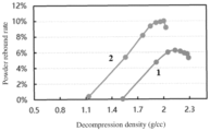
- Figure shows rebound rate curves of first and second negative electrode active materials in Example 10 of this application, where 1 represents the first negative electrode active material, and 2 represents the second negative electrode active material.
- a list of items connected by the terms “at least one of”, “at least one piece of”, “at least one kind of”, or the like may mean any combination of the listed items. For example, if items A and B are listed, the phrase “at least one of A and B” means only A; only B; or A and B. In another example, if items A, B, and C are listed, the phrase “at least one of A, B, and C” means only A, only B, only C, A and B (excluding C), A and C (excluding B), B and C (excluding A), or all of A, B, and C.
- the item A may contain one or more constituents.
- the item B may contain one or more constituents.
- the item C may contain a single constituent or a plurality of constituents.
- a secondary battery includes a negative electrode, the negative electrode includes a current collector and a negative electrode active material layer disposed on a surface of the current collector, the negative electrode active material layer includes a first negative electrode active material layer and a second negative electrode active material layer, the first negative electrode active material layer is disposed between the current collector and the second negative electrode active material layer, the first negative electrode active material layer includes a first negative electrode active material, the first negative electrode active material has a maximum rebound rate Ra, the second negative electrode active material layer includes a second negative electrode active material, and the second negative electrode active material has a maximum rebound rate Rb, where 5% ⁇ Ra ⁇ 13%, 10% ⁇ Rb ⁇ 17%, and Ra ⁇ Rb.
- the maximum rebound rate can reflect compressive resistance of the negative electrode active materials once they are made into electrode plates.
- a lower maximum rebound rate means smaller rebound after cold pressing of the corresponding electrode plate. This is beneficial for maintaining a high compacted density of the electrode plate, implying denser stacking between particles, and leading to reduced porosity of the electrode plate. Therefore, it is not conducive to the penetration of electrolyte and the diffusion of active ions, thereby affecting the fast charging capability of the secondary battery.
- a higher maximum rebound rate results in an electrode plate with a rich porous structure, which is beneficial for the penetration of electrolyte and the diffusion of active ions but the compacted density is low, which reduces the volumetric energy density of the secondary battery.
- the secondary battery of this application adopts a multi-layer active material layer design.
- the second negative electrode active material layer In the upper layer (the second negative electrode active material layer), the second negative electrode active material with a higher maximum rebound rate is selected, and in the lower layer (the first negative electrode active material layer), the first negative electrode active material with a lower maximum rebound rate is selected.
- the maximum rebound rates of the upper and lower active materials are controlled within the above ranges, so that the electrode plate not only has a high compacted density but also maintains a high surface porosity, thereby making the secondary battery have both high energy density and excellent fast charging capability.
- the maximum rebound rate of the active material represents the maximum degree of material rebound of the active material following pressurization and depressurization under different pressure conditions.
- the specific test method refer to the test method in the detailed embodiments below.
- Ra is 5%, 5.5%, 6%, 6.5%, 7%, 7.5%, 8%, 8.5%, 9%, 9.5%, 10%, 10.5%, 11%, 11.5%, 12%, 12.5%, or 13%, or in a range defined by any two of these values.
- the stacking is too dense. This reduces the porosity of the electrode plate, not conducive to the penetration of electrolyte and the diffusion of active ions, thereby affecting the fast charging capability of the secondary battery.
- 8% ⁇ Ra ⁇ 10% is 5%.
- Rb is 10%, 10.5%, 11%, 11.5%, 12%, 12.5%, 13%, 13.5%, 14%, 14.5%, 15%, 15.5%, 16%, 16.5%, or 17%, or in a range defined by any two of these values.
- Rb - Ra 0 ⁇ Rb - Ra ⁇ 10%.
- Rb - Ra is 0.5%, 1%, 1.5%, 2%, 2.5%, 3%, 3.5%, 4%, 4.5%, 5%, 5.5%, 6%, 6.5%, 7%, 7.5%, 8%, 8.5%, 9%, 9.5%, or 10%, or in a range defined by any two of these values.
- Rb - Ra falling within the above range can further improve the fast charging performance of the secondary battery while ensuring the volumetric energy density.
- PDa when the first negative electrode active material reaches its maximum rebound rate, its powder compacted density is PDa, where 1.95 g/cm 3 ⁇ PDa ⁇ 2.20 g/cm 3 .
- PDa is 1.95 g/cm 3 , 1.96 g/cm 3 , 1.98 g/cm 3 , 2.00 g/cm 3 , 2.01 g/cm 3 , 2.02 g/cm 3 , 2.03 g/cm 3 , 2.04 g/cm 3 , 2.05 g/cm 3 , 2.06 g/cm 3 , 2.07 g/cm 3 , 2.08 g/cm 3 , 2.09 g/cm 3 , 2.10 g/cm 3 , 2.11 g/cm 3 , 2.12 g/cm 3 , 2.13 g/cm 3 , 2.14 g/cm 3 , 2.15 g/cm 3 ,
- the first negative electrode active material meets the design with higher electrode compacted density and can maintain the integrity of the particle structure.
- PDb when the second negative electrode active material reaches its maximum rebound rate, its powder compacted density is PDb, where 1.75 g/cm 3 ⁇ PDb ⁇ 2.00 g/cm 3 .
- PDb is 1.75 g/cm 3 , 1.77 g/cm 3 , 1.79 g/cm 3 , 1.80 g/cm 3 , 1.81 g/cm 3 , 1.82 g/cm 3 , 1.83 g/cm 3 , 1.84 g/cm 3 , 1.85 g/cm 3 , 1.86 g/cm 3 , 1.87 g/cm 3 , 1.88 g/cm 3 , 1.89 g/cm 3 , 1.90 g/cm 3 , 1.91 g/cm 3 , 1.92 g/cm 3 , 1.93 g/cm 3 , 1.94 g/cm 3 , 1.95 g/cm 3 ,
- the second negative electrode active material has a higher rebound rate while maintaining a specified compacted density. In some embodiments, 1.80 g/cm 3 ⁇ PDb ⁇ 2.00 g/cm 3 .
- the powder compacted density when the active material reaches its maximum rebound rate is the limit compacted density of the material.
- the particle structure of the active material is damaged, and the particles transition from elastic deformation to inelastic deformation, decreasing the rebound rate.
- the first negative electrode active material is selected from artificial graphite and/or natural graphite. In some embodiments, the second negative electrode active material is selected from artificial graphite.
- the first negative electrode active material is selected from artificial graphite. In some embodiments, the second negative electrode active material is selected from artificial graphite.
- the method for preparing the first negative electrode active material includes the following steps.
- S1 Mix artificial graphite and/or natural graphite with a coating agent to obtain a first mixture.
- the coating agent in S 1, based on mass of the first mixture, has a mass percentage of 1% to 5%, for example, 2%, 3%, or 4%. In some implementations, the coating agent is asphalt.
- the first heat treatment is performed at 950°C to 1200°C, for example, 1000°C, 1050°C, 1100°C, or 1150°C. In some embodiments, in S2, the first heat treatment lasts for 1 h to 5 h, for example, 2 h, 3 h, or 4 h.
- the second heat treatment is performed at 500°C to 900°C, for example, 550°C, 600°C, 650°C, 700°C, 750°C, 800°C, or 850°C. In some embodiments, in S3, the second heat treatment lasts for 5 h to 15 h, for example, 6 h, 7 h, 8 h, 9 h, 10 h, 11 h, 12 h, 13 h, or 14 h.
- CO 2 in the mixed gas of CO 2 and N 2 , has a volume percentage of 3% to 7%, for example, 4%, 5%, or 6%.
- the method for preparing the second negative electrode active material includes the following steps.
- M1 Mix artificial graphite with a coating agent to obtain a second mixture.
- M2 Perform a third heat treatment on the second mixture in an inert atmosphere to obtain the second negative electrode active material.
- the coating agent in M1, based on mass of the second mixture, has a mass percentage of 1% to 5%, for example, 2%, 3%, or 4%. In some implementations, the coating agent is asphalt.
- the third heat treatment is performed at 700°C to 1100°C, for example, 750°C, 800°C, 850°C, 900°C, 950°C, 1000°C, or 1050°C. In some embodiments, in M2, the third heat treatment lasts for 4 h to 10 h, for example, 5 h, 6 h, 7 h, 8 h, or 9 h.
- artificial graphite is obtained from carbonaceous materials such as needle coke, petroleum coke, asphalt coke, and the like through high-temperature graphitization.
- natural graphite is obtained from natural flake graphite through acid pickling and ball milling.
- the first negative electrode active material layer has a mass percentage of 60% to 90%, for example, 60%, 65%, 70%, 75%, 80%, 85%, or 90%.
- the second negative electrode active material layer has a mass percentage of 10% to 40%, for example, 10%, 15%, 20%, 25%, 30%, 35%, or 40%.
- the secondary battery achieves both high energy density and excellent electrochemical performance.
- the second negative electrode active material layer has a mass percentage greater than 40%, and the first negative electrode active material layer has a mass percentage less than 60%, the secondary battery experiences significant loss in energy density.
- the second negative electrode active material layer has a mass percentage less than 10%, and the first negative electrode active material layer has a mass percentage greater than 90%, the fast charging capability of the secondary battery significantly decreases.
- the first negative electrode active material when tested with N-methyl pyrrolidone as a test oil, has an oil absorption value less than or equal to 65 mL/100g, and the second negative electrode active material has an oil absorption value less than or equal to 65 mL/100g.
- the oil absorption value of the active material reflects the lipophilic property of the particles. If the oil absorption value is too high, more dispersant is needed to evenly disperse the active material particles in the slurry, reducing the proportion of active material in the slurry, thereby affecting the energy density and kinetic performance of the secondary battery.
- an adhesion force between the negative electrode active material layer and the current collector is greater than or equal to 8N/m. If the adhesion force is too low, the electrode plate is prone to powder dropping and delamination during processing and cycling. Therefore, it is specified that the adhesion force is greater than or equal to 8N/m to ensure stable structure of the electrode plate.
- the compacted density of the negative electrode is 1.70 g/cm 3 to 1.85 g/cm 3 . In some embodiments, the compacted density of the negative electrode is 1.70 g/cm 3 , 1.73 g/cm 3 , 1.75 g/cm 3 , 1.77 g/cm 3 , 1.80 g/cm 3 , 1.83 g/cm 3 , or 1.85 g/cm 3 , or in a range defined by any two of these values. Excessively high compacted density of the negative electrode may cause overpressing of the electrode plate, adversely affecting the electrode processing and electrical performance. Excessively low compacted density of the negative electrode cannot effectively improve the energy density of the secondary battery.
- the rebound rate of the negative electrode plate is T, where 15% ⁇ T ⁇ 20%, for example, 16%, 17%, 18%, or 19%.
- the negative electrode active material layer further includes a binder and a conductive agent.
- the binder includes at least one of styrene-butadiene rubber, polyacrylic acid, polyacrylate, polyimide, polyamide-imide, polyvinylidene fluoride, polyvinylidene difluoride, polytetrafluoroethylene, water-based acrylic resin, polyvinyl alcohol formaldehyde, or styrene-acrylic copolymer.
- any conductive material that does not cause chemical changes can be used as the conductive material.
- the conductive material includes at least one of conductive carbon black, acetylene black, carbon nanotubes, Ketjen black, conductive graphite, or graphene.
- the negative electrode current collector may be copper foil, nickel foil, stainless steel foil, titanium foil, nickel foam, copper foam, a polymer substrate coated with a conductive metal, or a combination thereof.
- the secondary battery further includes a positive electrode.
- the positive electrode includes a positive electrode current collector and a positive electrode active material layer.
- the positive electrode active material layer includes a positive electrode active material, a binder, and a conductive agent.
- the positive electrode active material may include at least one of lithium cobalt oxide, lithium nickel manganese cobalt oxide, lithium nickel manganese aluminum oxide, lithium iron phosphate, lithium vanadium phosphate, lithium cobalt phosphate, lithium manganese phosphate, lithium manganese iron phosphate, lithium iron silicate, lithium vanadium silicate, lithium cobalt silicate, lithium manganese silicate, spinel lithium manganese oxide, spinel lithium nickel manganese oxide, or lithium titanate.
- the binder may include various adhesive polymers, such as at least one of polyvinylidene fluoride, polytetrafluoroethylene, polyolefins, sodium carboxymethyl cellulose, lithium carboxymethyl cellulose, modified polyvinylidene fluoride, modified SBR rubber, or polyurethane.
- adhesive polymers such as at least one of polyvinylidene fluoride, polytetrafluoroethylene, polyolefins, sodium carboxymethyl cellulose, lithium carboxymethyl cellulose, modified polyvinylidene fluoride, modified SBR rubber, or polyurethane.
- any conductive material that does not cause chemical changes can be used as the conductive agent.
- the conductive agent examples include: a carbon-based material such as natural graphite, artificial graphite, carbon black, acetylene black, Ketjen black, and carbon fiber; a metal-based material such as metal powder or metal fiber including copper, nickel, aluminum, silver, or the like; a conductive polymer such as a polyphenylene derivative; or a mixture thereof.
- the positive electrode current collector may be a metal foil or a composite current collector.
- an aluminum foil may be used.
- the composite current collector may be formed by forming a metal material (copper, copper alloy, nickel, nickel alloy, titanium, titanium alloy, silver, silver alloy, or the like) on a polymer matrix.
- the secondary battery in this application further includes a separator.
- a material or shape of the separator used in the secondary battery according to this application is not particularly limited, and may be based on any technology disclosed in the prior art.
- the separator includes a polymer or an inorganic substance formed by a material stable to the electrolyte of this application.
- the separator may include a substrate layer and a surface treatment layer.
- the substrate layer is non-woven fabric, a membrane, or a composite membrane having a porous structure, and a material of the substrate layer is at least one selected from polyethylene, polypropylene, polyethylene terephthalate, or polyimide.
- a polypropylene porous membrane, a polyethylene porous membrane, polypropylene non-woven fabric, polyethylene non-woven fabric, or a polypropylene-polyethylene-polypropylene porous composite membrane may be selected.
- the surface treatment layer is provided on at least one surface of the substrate layer, and the surface treatment layer may be a polymer layer or an inorganic layer, or may be a layer formed by mixing a polymer and an inorganic substance.
- the inorganic substance layer includes inorganic particles and a binder.
- the inorganic particles are at least one selected from aluminum oxide, silicon oxide, magnesium oxide, titanium oxide, hafnium oxide, tin oxide, ceria oxide, nickel oxide, zinc oxide, calcium oxide, zirconium oxide, yttrium oxide, silicon carbide, boehmite, aluminum hydroxide, magnesium hydroxide, calcium hydroxide, or barium sulfate.
- the binder is at least one selected from polyvinylidene fluoride, a vinylidene fluoride-hexafluoropropylene copolymer, polyamide, polyacrylonitrile, polyacrylate, polyacrylic acid, polyacrylate, polyvinylpyrrolidone, polyvinyl ether, polymethyl methacrylate, polytetrafluoroethylene, or polyhexafluoropropylene.
- the polymer layer includes a polymer, and a material of the polymer is at least one selected from polyamide, polyacrylonitrile, an acrylate polymer, polyacrylic acid, polyacrylate, polyvinylpyrrolidone, polyvinyl ether, polyvinylidene fluoride, or poly(vinylidene fluoride-hexafluoropropylene).
- the secondary battery in this application further includes an electrolyte.
- the electrolyte that can be used in this application may be an electrolyte known in the prior art.
- the electrolyte includes an organic solvent, a lithium salt, and an optional additive.
- the organic solvent of the electrolyte according to this application may be any organic solvent known in the prior art which can be used as a solvent of the electrolyte.
- An electrolytic salt used in the electrolyte according to this application is not limited, and may be any electrolytic salt known in the prior art.
- the additive of the electrolyte according to this application may be any additive known in the prior art which can be used as an additive of the electrolyte.
- the organic solvent includes but is not limited to ethylene carbonate (EC), propylene carbonate (PC), diethyl carbonate (DEC), ethyl methyl carbonate (EMC), dimethyl carbonate (DMC), propylene carbonate, or ethyl propionate.
- the organic solvent includes an ether solvent, for example, at least one of 1,3-dioxolane (DOL) or dimethoxyethane (DME).
- the lithium salt includes at least one of an organic lithium salt or an inorganic lithium salt.
- the lithium salt includes but is not limited to lithium hexafluorophosphate (LiPF 6 ), lithium tetrafluoroborate (LiBF 4 ), lithium difluorophosphate (LiPO 2 F 2 ), lithium bistrifluoromethanesulfonimide LiN(CF 3 SO 2 ) 2 (LiTFSI), lithium bis(fluorosulfonyl)imide Fi(N(SO 2 F) 2 ) (LiFSI), lithium bis(oxalate) borate FiB(C 2 O 4 ) 2 (LiBOB), or lithium difluoro(oxalato)borate FiBF 2 (C 2 O 4 ) (LiDFOB).
- the additive includes at least one of fluoroethylene carbonate or adiponitrile.
- the secondary battery is a wound secondary battery or a laminated secondary battery.
- the secondary battery of this application includes but is not limited to a lithium-ion battery or a sodium-ion battery. In some embodiments, the secondary battery includes a lithium-ion secondary battery.
- This application further provides an electronic apparatus including the secondary battery according to the first aspect of this application.
- the electronic device or apparatus in this application is not particularly limited.
- the electronic device of this application includes but is not limited to a notebook computer, a pen-input computer, a mobile computer, an electronic book player, a portable telephone, a portable fax machine, a portable copier, a portable printer, a stereo headset, a video recorder, a liquid crystal television, a portable cleaner, a portable CD player, a mini-disc, a transceiver, an electronic notebook, a calculator, a memory card, a portable recorder, a radio, a standby power source, a motor, an automobile, a motorcycle, a motor bicycle, a bicycle, a lighting appliance, a toy, a game console, a clock, an electric tool, a flash lamp, a camera, a large household battery, or a lithium-ion capacitor.
- First negative electrode active material 5 kg of artificial graphite material was weighed, and mixed to uniformity with asphalt as a coating agent to obtain a first mixture, where a mass ratio of asphalt to graphite material was 3:97.
- the first mixture underwent a first heat treatment, where conditions for the first heat treatment were as follows: the reaction lasted for 2h at 1000°C under a nitrogen atmosphere. After the reaction ended and the resulting product was cooled to room temperature, a first heat treatment product was obtained.
- the first heat treatment product underwent a second heat treatment, where conditions for the second heat treatment were as follows: the reaction atmosphere was a mixed gas of 5% CO 2 and 95% N 2 , and the reaction lasted for 6h at 900°C. After the reaction ended and the resulting product was cooled to room temperature, a first negative electrode active material was obtained.
- Second negative electrode active material 5 kg of artificial graphite material was weighed, and mixed to uniformity with asphalt as a coating agent to obtain a second mixture, where a mass ratio of asphalt to graphite material was 4:96.
- the second mixture underwent a third heat treatment, where conditions for the third heat treatment were as follows: the reaction temperature T2 was 700°C and the reaction time H2 under a nitrogen atmosphere was 4 h. After the reaction ended and the resulting product was cooled to room temperature, a second negative electrode active material was obtained.
- reaction temperature T1 and reaction time H1 in the mixture atmosphere of 5% CO 2 and 95% N 2 for preparing the first negative electrode active material, and the reaction temperature T2 and reaction time H2 for preparing the second negative electrode active material in Example 1 were adjusted to prepare other examples and comparative examples.
- the first negative electrode active material, sodium carboxymethyl cellulose (CMC), and styrene-butadiene rubber (SBR) were dispersed uniformly in an appropriate amount of deionized water at a mass ratio of 97.5:1.2:1.3 to obtain slurry 1.
- the second negative electrode active material, sodium carboxymethyl cellulose (CMC), and styrene-butadiene rubber (SBR) were dispersed uniformly in an appropriate amount of deionized water at a mass ratio of 97.5:1.2:1.3 to obtain slurry 2.
- Copper foil was used as a current collector, with slurry 1 as a first negative electrode active material layer and slurry 2 as a second negative electrode active material layer uniformly applied on the current collector.
- a negative electrode plate also known as a negative electrode
- the first negative electrode active material layer had a mass percentage of 70%
- the second negative electrode active material layer had a mass percentage of 30%.
- Lithium cobalt oxide (chemical formula: LiCoO 2 ) was used as an active material of a positive electrode and was mixed with a conductive agent acetylene black and a binder polyvinylidene fluoride (abbreviated as PVDF) at a weight ratio of 96.3:2.2:1.5 in an appropriate amount of N-methyl pyrrolidone (abbreviated as NMP) solvent until fully stirred and mixed, to form a uniform positive electrode slurry.
- NMP N-methyl pyrrolidone
- fluoroethylene carbonate and 1,3-propanesultone were added, dissolved, and stirred thoroughly.
- a lithium salt LiPF 6 was added, and mixed to uniformity to obtain an electrolyte.
- LiPF 6 had a mass percentage of 12.5%
- fluoroethylene carbonate had a mass percentage of 2%
- 1,3-propanesultone had a mass percentage of 2%, with the mass percentages of all substances calculated based on mass of the electrolyte.
- a polyethylene porous polymer film was used as a separator.
- the positive electrode, the separator, and the negative electrode were stacked in order, so that the separator was placed between the positive electrode and the negative electrode for separation. Then the stack was wound to obtain an electrode assembly. After welded with tabs, the electrode assembly was then placed in an outer packaging aluminum foil film. Then the prepared electrolyte was injected into the dried electrode assembly, followed by processes such as vacuum packaging, standing, formation, shaping, and capacity testing, to obtain a pouch lithium-ion battery.
- the preparation of the negative electrode active material was the same as that in Example 9.
- the preparation of the negative electrode was similar to that in Example 9, with the differences lying in that the mass percentages of the first and second negative electrode active material layers were adjusted by adjusting the coating weight of the slurry.
- the specific adjusted mass percentages of the first and second negative electrode active material layers are shown in Table 2.
- the preparation of the positive electrode, separator, electrolyte, and lithium-ion battery was the same as that in Example 9.
- a fully discharged lithium-ion battery was taken apart, and the negative electrode was removed and soaked in DMC (dimethyl carbonate) for 20 min, and then sequentially rinsed with DMC and acetone to remove the electrolyte and surface SEI film. Afterwards, the battery was placed in an oven and baked at 80°C for 12 h to obtain the treated negative electrode plate.
- DMC dimethyl carbonate
- a scraper was used to scrape off M1 grams of powder from the negative electrode plate within a thickness range of 10 ⁇ m from the surface, and the scraped powder was calcined at 500°C in an air atmosphere for 3 h to obtain the first negative electrode active material.
- a scraper was used to scrape off M2 grams of powder from the negative electrode plate within a thickness range of 10 ⁇ m from the current collector, and the scraped powder was calcined at 500°C in an air atmosphere for 3 h to obtain the second negative electrode active material.
- the obtained first and second negative electrode active materials were tested as follows:
- a PRCD3100 powder compacted density meter was used to test the rebound rate and powder compacted density at the maximum rebound rate of the active material, that is, the limit compacted density.
- a DABS-H oil absorption meter was used to determine the oil absorption value of the active material. Specifically, N-methyl pyrrolidone was added to the sample in the mixing tank of the oil absorption meter with a constant speed burette. As the oil absorption of the sample increased, the viscosity of the mixture continuously increased. When the viscosity reached a predetermined value, the oil absorption meter and burette simultaneously shut off. The volume of oil added was directly read from the burette, and the volume of oil absorbed per unit mass of the sample was recorded as the oil absorption value of the sample.
- T1 The thickness of the negative electrode plate after cold pressing was measured as T1
- T2 the thickness of the negative electrode plate from a 50% SOC cell was measured as T2
- the lithium-ion battery underwent capacity testing according to the following procedure:
- the discharge capacity recorded in step (4) was C
- the discharge platform voltage was P
- the thickness of the lithium-ion battery was measured as G
- the width of the lithium-ion battery was W
- E C ⁇ P / G ⁇ L ⁇ W
- the discharge capacity of the last cycle was recorded as D10
- the charge capacity of the first cycle was recorded as C1
- Table 1 shows the impact of the maximum rebound rate Ra of the first negative electrode active material and the maximum rebound rate Rb of the second negative electrode active material on the performance of the lithium-ion battery.
- Table 1 Preparation parameters Negative electrode Lithium-ion battery Example and comparative example H1 (h) H2 (h) Reaction temperature of first negative electrode active material T1 (°C) Reaction temperature of second negative electrode active material T2 (°C) Maximum rebound rate Ra of first negative electrode active material Maximum rebound rate Rb of second negative electrode active material Rb - Ra Rebound rate T at 50% SOC of negative electrode Volumetri c energy density (Wh/L) Irreversible Li loss rate Q Example 1 6 4 900 700 5% 17% 12% 19% 748 1.20% Example 2 6 4 850 750 6% 16% 10% 17% 749 1.30% Example 3 6 4 800 800 7% 15% 8% 16% 750 1.30% Example 4 6 4 750 850 8% 14% 6% 16% 751 1.40% Example 5 6 4 700 900 9% 13%
- Table 2 further describes, based on Example 9, the impact of the mass percentage Wa of the first negative electrode active material layer and the mass percentage Wb of the second negative electrode active material layer on the performance of the lithium-ion battery.
- Table 2 Example Negative electrode Lithium-ion battery Wa Wb Rebound rate T at 50% SOC of negative electrode Volumetric energy density E (Wh/L) Irreversible Li loss rate Q
- Example 9 70% 30% 16% 752 1.20%
- Example 14 55% 45% 18% 745 1.20%
- Example 15 60% 40% 17% 750 1.40%
- Example 16 65% 35% 17% 751 1.50%
- Example 17 75% 25% 16% 753 1.70%
- Example 18 80% 20% 16% 754 1.80%
- Example 19 85% 15% 15% 755 1.90%
- Example 20 90% 10% 15% 756 2.00%
- the lithium-ion battery has both high energy density and excellent fast charging performance.
Landscapes
- Chemical & Material Sciences (AREA)
- Chemical Kinetics & Catalysis (AREA)
- Electrochemistry (AREA)
- General Chemical & Material Sciences (AREA)
- Engineering & Computer Science (AREA)
- Manufacturing & Machinery (AREA)
- Materials Engineering (AREA)
- Composite Materials (AREA)
- Inorganic Chemistry (AREA)
- Battery Electrode And Active Subsutance (AREA)
Abstract
Description
- This application relates to the field of energy storage and specifically to a secondary battery and an electronic apparatus.
- As the market for secondary batteries continues to expand, the performance requirements for secondary batteries are also increasing, with energy density and fast charging capability as particularly important indicators. Conventional electrode plate designs in existing secondary batteries are typically single-layered, and the active materials used struggle to provide both high energy density and fast charging capability. Usually, to enhance the fast charging capability of secondary batteries, the coating weight needs to be reduced, or to increase the energy density of lithium secondary batteries, the coating weight needs to be increased. However, reducing the coating weight to improve the fast charging capability of secondary batteries leads to significant loss in energy density due to the lesser amount of active material. Similarly, increasing the coating weight to enhance the energy density of secondary batteries results in poor fast charging capability due to the thicker electrode plates which extend the path for active ion transport.
- In view of the above problems existing in the prior art, this application provides a secondary battery. The secondary battery of this application employs a specific multi-layer electrode plate design, which significantly enhances the fast charging performance while minimizing the impact on the volumetric energy density of the secondary battery, thereby achieving both high energy density and excellent fast charging capability.
- A first aspect of this application provides a secondary battery, where the secondary battery includes a negative electrode, the negative electrode includes a current collector and a negative electrode active material layer disposed on a surface of the current collector, the negative electrode active material layer includes a first negative electrode active material layer and a second negative electrode active material layer, the first negative electrode active material layer is disposed between the current collector and the second negative electrode active material layer, the first negative electrode active material layer includes a first negative electrode active material, the first negative electrode active material has a maximum rebound rate Ra, the second negative electrode active material layer includes a second negative electrode active material, and the second negative electrode active material has a maximum rebound rate Rb, where 5% ≤ Ra ≤ 13%, 10% ≤ Rb ≤ 17%, and Ra < Rb. For negative electrode active materials such as graphite materials, the maximum rebound rate can reflect compressive resistance of the negative electrode active materials once they are made into electrode plates. A lower maximum rebound rate means smaller rebound after cold pressing of the corresponding electrode plate. This is beneficial for maintaining a high compacted density of the electrode plate, implying denser stacking between particles, and leading to reduced porosity of the electrode plate. Therefore, it is not conducive to the penetration of electrolyte and the diffusion of active ions, thereby affecting the fast charging capability of the secondary battery. A higher maximum rebound rate results in an electrode plate with a rich porous structure, which is beneficial for the penetration of electrolyte and the diffusion of active ions but the compacted density is low, which reduces the volumetric energy density of the secondary battery. The secondary battery of this application adopts a multi-layer active material layer design. In the upper layer (the second negative electrode active material layer), the second negative electrode active material with a higher maximum rebound rate is selected, and in the lower layer (the first negative electrode active material layer), the first negative electrode active material with a lower maximum rebound rate is selected. At the same time, the maximum rebound rates of the upper and lower active materials are controlled within the above ranges, so that the electrode plate not only has a high compacted density but also maintains a high surface porosity, thereby making the secondary battery have both high energy density and excellent fast charging capability.
- In some embodiments, 5% ≤ Ra ≤ 10%, and 10% ≤ Rb ≤ 14%. In some embodiments, 8% ≤ Ra ≤ 10%, and 12% ≤ Rb ≤ 14%. When the maximum rebound rate of the first negative electrode active material is too low, the stacking becomes too dense, which reduces the porosity of the electrode plate, not conducive to the penetration of electrolyte and the diffusion of active ions, thereby affecting the fast charging capability of the secondary battery. When the maximum rebound rate of the second negative electrode active material is too high, although this benefits the enhancement of fast charging capability, this results in an excessively low compacted density, leading to loss in the volumetric energy density of the secondary battery.
- In some embodiments, 5% ≤ Ra ≤ 10%. In some embodiments, 8% ≤ Ra ≤ 10%.
- In some embodiments, 10% ≤ Rb ≤ 14%. In some embodiments, 12% ≤ Rb ≤ 14%.
- In some embodiments, 0 < Rb - Ra ≤ 10%. Rb - Ra falling within the above range can further enhance the fast charging performance of the secondary battery while ensuring the volumetric energy density. In some embodiments, 2% ≤ Rb - Ra ≤ 6%.
- In some embodiments, when the first negative electrode active material reaches its maximum rebound rate, its powder compacted density is PDa, where 1.95 g/cm3 ≤ PDa ≤ 2.20 g/cm3. In some embodiments, 2.00 g/cm3 ≤ PDa ≤ 2.20 g/cm3. When the PDa of the first negative electrode active material is within the above range, the first negative electrode active material meets the design with higher electrode compacted density and can maintain the integrity of the particle structure.
- In some embodiments, when the second negative electrode active material reaches its maximum rebound rate, its powder compacted density is PDb, where 1.75 g/cm3 ≤ PDb ≤ 2.00 g/cm3. In some embodiments, 1.80 g/cm3 ≤ PDb ≤ 2.00 g/cm3. When the PDb of the second negative electrode active material is within the above range, the second negative electrode active material has a higher rebound rate while maintaining a specified compacted density.
- In some embodiments, the first negative electrode active material is selected from artificial graphite, and the second negative electrode active material is selected from artificial graphite.
- In some embodiments, based on mass of the negative electrode active material layer, the first negative electrode active material layer has a mass percentage of 60% to 80%. In some embodiments, based on the mass of the negative electrode active material layer, the second negative electrode active material layer has a mass percentage of 20% to 40%. When the percentages of the first and second negative electrode active material layers are within the above ranges, the secondary battery achieves both high energy density and excellent electrochemical performance. When the second negative electrode active material layer has a mass percentage greater than 40%, and the first negative electrode active material layer has a mass percentage less than 60%, the secondary battery experiences significant loss in energy density. When the second negative electrode active material layer has a mass percentage less than 20%, and the first negative electrode active material layer has a mass percentage greater than 80%, the fast charging capability of the secondary battery significantly decreases.
- In some embodiments, when tested with N-methyl pyrrolidone as a test oil, the first negative electrode active material has an oil absorption value less than or equal to 65 mL/100g, and the second negative electrode active material has an oil absorption value less than or equal to 65 mL/100g. The oil absorption value of the active material reflects the lipophilic property of the particles. If the oil absorption value is too high, more dispersant is needed to evenly disperse the active material particles in the slurry, reducing the proportion of active material in the slurry, thereby affecting the energy density and kinetic performance of the secondary battery.
- In some embodiments, an adhesion force between the negative electrode active material layer and the current collector is greater than or equal to 8N/m. If the adhesion force is too low, the electrode plate is prone to powder dropping and delamination during processing and cycling. Therefore, it is specified that the adhesion force is greater than or equal to 8N/m to ensure stable structure of the electrode plate.
- In some embodiments, the compacted density of the negative electrode is 1.70 g/cm3 to 1.85 g/cm3. Excessively high compacted density of the negative electrode may cause overpressing of the electrode plate, adversely affecting the electrode plate processing and electrical performance. Excessively low compacted density of the negative electrode cannot effectively improve the energy density of the secondary battery.
- In some embodiments, the rebound rate of the negative electrode plate at 50% SOC is T, where 15% ≤ T ≤ 20%.
- A second aspect of this application provides an electronic apparatus including the secondary battery according to the first aspect.
- The secondary battery of this application employs a multi-layer electrode plate design. The layer close to the current collector uses a negative electrode active material with a lower maximum rebound rate, ensuring higher compacted density of the electrode plate. The upper layer uses a negative electrode active material with a higher maximum rebound rate, ensuring higher porosity of the electrode plate surface, facilitating the infiltration and penetration of the electrolyte, as well as the diffusion of lithium ions. Such design allows the electrode plate to not only have a high compacted density but also maintain a high surface porosity, thereby allowing the secondary battery to achieve both high energy density and excellent fast charging capability.
- A third aspect of this application provides a method for preparing a negative electrode. The method of negative electrode includes preparing a first active material and preparing a second active material; where the first active material is obtained by coating natural graphite and/or artificial graphite, followed by two different heat treatments, and the second active material is obtained by coating artificial graphite, followed by one heat treatment.
- Specifically, preparation of the first active material: mixing artificial graphite and/or natural graphite with a coating agent to obtain a first mixture, where based on mass of the first mixture, the coating agent has a mass percentage of 1% to 5%; in an inert atmosphere, performing a first heat treatment on the first mixture to obtain a first heat treatment product; and in a mixed gas of CO2 and N2, performing a second heat treatment on the first heat treatment product to obtain the first active material.
- Preparation of the second active material: mixing artificial graphite with a coating agent to obtain a second mixture, where based on mass of the second mixture, the coating agent has a mass percentage of 1% to 5%; and in an inert atmosphere, performing a third heat treatment on the second mixture to obtain the second active material.
- The first heat treatment is performed at 950°C to 1200°C, and the first heat treatment lasts for 1 h to 5 h; the second heat treatment is performed at 500°C to 900°C, and the second heat treatment lasts for 5 h to 15 h; the third heat treatment is performed at a temperature of 700°C to 1100°C, and the third heat treatment lasts for 4 h to 10 h; and the coating agent is asphalt.
- The above first and second active materials are used as the first and second active material layers of the negative electrode, respectively, and the second active material layer is placed on the upper surface of the first active material layer (that is, the surface of the negative electrode away from the current collector in a thickness direction), so that the secondary battery achieves both higher energy density and fast charging capability.
- Figure shows rebound rate curves of first and second negative electrode active materials in Example 10 of this application, where 1 represents the first negative electrode active material, and 2 represents the second negative electrode active material.
- In the descriptions of this application, "more than" or "less than" is inclusive of the present number unless otherwise specified.
- Unless otherwise specified, the terms used in this application have well known meanings commonly understood by persons skilled in the art. Unless otherwise specified, numerical values of parameters mentioned in this application may be measured by using various measurement methods commonly used in the art (for example, they may be tested by using the methods provided in the embodiments of this application).
- A list of items connected by the terms "at least one of", "at least one piece of", "at least one kind of", or the like may mean any combination of the listed items. For example, if items A and B are listed, the phrase "at least one of A and B" means only A; only B; or A and B. In another example, if items A, B, and C are listed, the phrase "at least one of A, B, and C" means only A, only B, only C, A and B (excluding C), A and C (excluding B), B and C (excluding A), or all of A, B, and C. The item A may contain one or more constituents. The item B may contain one or more constituents. The item C may contain a single constituent or a plurality of constituents.
- The following clearly and completely describes the technical solutions in some embodiments of this application with reference to the accompanying drawings in some embodiments of this application. Apparently, the described embodiments are only some rather than all of the embodiments of this application. In absence of conflicts, the following embodiments and features in these embodiments may be combined.
- A secondary battery according to this application includes a negative electrode, the negative electrode includes a current collector and a negative electrode active material layer disposed on a surface of the current collector, the negative electrode active material layer includes a first negative electrode active material layer and a second negative electrode active material layer, the first negative electrode active material layer is disposed between the current collector and the second negative electrode active material layer, the first negative electrode active material layer includes a first negative electrode active material, the first negative electrode active material has a maximum rebound rate Ra, the second negative electrode active material layer includes a second negative electrode active material, and the second negative electrode active material has a maximum rebound rate Rb, where 5% ≤ Ra ≤ 13%, 10% ≤ Rb ≤ 17%, and Ra < Rb. For negative electrode active materials such as graphite materials, the maximum rebound rate can reflect compressive resistance of the negative electrode active materials once they are made into electrode plates. A lower maximum rebound rate means smaller rebound after cold pressing of the corresponding electrode plate. This is beneficial for maintaining a high compacted density of the electrode plate, implying denser stacking between particles, and leading to reduced porosity of the electrode plate. Therefore, it is not conducive to the penetration of electrolyte and the diffusion of active ions, thereby affecting the fast charging capability of the secondary battery. A higher maximum rebound rate results in an electrode plate with a rich porous structure, which is beneficial for the penetration of electrolyte and the diffusion of active ions but the compacted density is low, which reduces the volumetric energy density of the secondary battery. The secondary battery of this application adopts a multi-layer active material layer design. In the upper layer (the second negative electrode active material layer), the second negative electrode active material with a higher maximum rebound rate is selected, and in the lower layer (the first negative electrode active material layer), the first negative electrode active material with a lower maximum rebound rate is selected. At the same time, the maximum rebound rates of the upper and lower active materials are controlled within the above ranges, so that the electrode plate not only has a high compacted density but also maintains a high surface porosity, thereby making the secondary battery have both high energy density and excellent fast charging capability.
- In this application, the maximum rebound rate of the active material represents the maximum degree of material rebound of the active material following pressurization and depressurization under different pressure conditions. For the specific test method, refer to the test method in the detailed embodiments below.
- In some embodiments, Ra is 5%, 5.5%, 6%, 6.5%, 7%, 7.5%, 8%, 8.5%, 9%, 9.5%, 10%, 10.5%, 11%, 11.5%, 12%, 12.5%, or 13%, or in a range defined by any two of these values. When the maximum rebound rate of the first negative electrode active material is too low, the stacking is too dense. This reduces the porosity of the electrode plate, not conducive to the penetration of electrolyte and the diffusion of active ions, thereby affecting the fast charging capability of the secondary battery. In some embodiments, 5% ≤ Ra ≤ 10%. In some embodiments, 8% ≤ Ra ≤ 10%.
- In some embodiments, Rb is 10%, 10.5%, 11%, 11.5%, 12%, 12.5%, 13%, 13.5%, 14%, 14.5%, 15%, 15.5%, 16%, 16.5%, or 17%, or in a range defined by any two of these values. When the maximum rebound rate of the second negative electrode active material is too high, although this benefits the enhancement of fast charging capability, this results in an excessively low compacted density, leading to loss in the volumetric energy density of the secondary battery. In some embodiments, 10% ≤ Rb ≤ 14%. In some embodiments, 12% ≤ Rb ≤ 14%.
- In some embodiments, 5% ≤ Ra ≤ 10%, and 10% ≤ Rb ≤ 14%. In some embodiments, 8% ≤ Ra ≤ 10%, and 12% ≤ Rb ≤ 14%.
- In some embodiments, 0 < Rb - Ra ≤ 10%. In some embodiments, Rb - Ra is 0.5%, 1%, 1.5%, 2%, 2.5%, 3%, 3.5%, 4%, 4.5%, 5%, 5.5%, 6%, 6.5%, 7%, 7.5%, 8%, 8.5%, 9%, 9.5%, or 10%, or in a range defined by any two of these values. Rb - Ra falling within the above range can further improve the fast charging performance of the secondary battery while ensuring the volumetric energy density. In some embodiments, 2% ≤ Rb - Ra ≤ 6%.
- In some embodiments, when the first negative electrode active material reaches its maximum rebound rate, its powder compacted density is PDa, where 1.95 g/cm3 ≤ PDa ≤ 2.20 g/cm3. In some embodiments, PDa is 1.95 g/cm3, 1.96 g/cm3, 1.98 g/cm3, 2.00 g/cm3, 2.01 g/cm3, 2.02 g/cm3, 2.03 g/cm3, 2.04 g/cm3, 2.05 g/cm3, 2.06 g/cm3, 2.07 g/cm3, 2.08 g/cm3, 2.09 g/cm3, 2.10 g/cm3, 2.11 g/cm3, 2.12 g/cm3, 2.13 g/cm3, 2.14 g/cm3, 2.15 g/cm3, 2.16 g/cm3, 2.17 g/cm3, 2.18 g/cm3, 2.19 g/cm3, or 2.20 g/cm3, or in a range defined by any two of these values. When the PDa of the first negative electrode active material is within the above range, the first negative electrode active material meets the design with higher electrode compacted density and can maintain the integrity of the particle structure. In some embodiments, 2.00 g/cm3 ≤ PDa ≤ 2.20 g/cm3.
- In some embodiments, when the second negative electrode active material reaches its maximum rebound rate, its powder compacted density is PDb, where 1.75 g/cm3 ≤ PDb ≤ 2.00 g/cm3. In some embodiments, PDb is 1.75 g/cm3, 1.77 g/cm3, 1.79 g/cm3, 1.80 g/cm3, 1.81 g/cm3, 1.82 g/cm3, 1.83 g/cm3, 1.84 g/cm3, 1.85 g/cm3, 1.86 g/cm3, 1.87 g/cm3, 1.88 g/cm3, 1.89 g/cm3, 1.90 g/cm3, 1.91 g/cm3, 1.92 g/cm3, 1.93 g/cm3, 1.94 g/cm3, 1.95 g/cm3, 1.96 g/cm3, 1.97 g/cm3, 1.98 g/cm3, 1.99 g/cm3, or 2.00 g/cm3, or in a range defined by any two of these values. When the PDb of the second negative electrode active material is within the above range, the second negative electrode active material has a higher rebound rate while maintaining a specified compacted density. In some embodiments, 1.80 g/cm3 ≤ PDb ≤ 2.00 g/cm3.
- In this application, the powder compacted density when the active material reaches its maximum rebound rate is the limit compacted density of the material. When pressure is further applied, the particle structure of the active material is damaged, and the particles transition from elastic deformation to inelastic deformation, decreasing the rebound rate. For the specific test method, refer to the test method in the detailed embodiments below.
- In some embodiments, the first negative electrode active material is selected from artificial graphite and/or natural graphite. In some embodiments, the second negative electrode active material is selected from artificial graphite.
- In some embodiments, the first negative electrode active material is selected from artificial graphite. In some embodiments, the second negative electrode active material is selected from artificial graphite.
- In some embodiments, the method for preparing the first negative electrode active material includes the following steps.
- S1: Mix artificial graphite and/or natural graphite with a coating agent to obtain a first mixture.
- S2: Perform a first heat treatment on the first mixture in an inert atmosphere to obtain a first heat treatment product.
- S3: Perform a second heat treatment on the first heat treatment product in a mixed gas of CO2 and N2 to obtain the first negative electrode active material.
- In some embodiments, in S 1, based on mass of the first mixture, the coating agent has a mass percentage of 1% to 5%, for example, 2%, 3%, or 4%. In some implementations, the coating agent is asphalt.
- In some embodiments, in S2, the first heat treatment is performed at 950°C to 1200°C, for example, 1000°C, 1050°C, 1100°C, or 1150°C. In some embodiments, in S2, the first heat treatment lasts for 1 h to 5 h, for example, 2 h, 3 h, or 4 h.
- In some embodiments, in S3, the second heat treatment is performed at 500°C to 900°C, for example, 550°C, 600°C, 650°C, 700°C, 750°C, 800°C, or 850°C. In some embodiments, in S3, the second heat treatment lasts for 5 h to 15 h, for example, 6 h, 7 h, 8 h, 9 h, 10 h, 11 h, 12 h, 13 h, or 14 h.
- In some embodiments, in the mixed gas of CO2 and N2, CO2 has a volume percentage of 3% to 7%, for example, 4%, 5%, or 6%.
- In some embodiments, the method for preparing the second negative electrode active material includes the following steps.
- M1: Mix artificial graphite with a coating agent to obtain a second mixture.
- M2: Perform a third heat treatment on the second mixture in an inert atmosphere to obtain the second negative electrode active material.
- In some embodiments, in M1, based on mass of the second mixture, the coating agent has a mass percentage of 1% to 5%, for example, 2%, 3%, or 4%. In some implementations, the coating agent is asphalt.
- In some embodiments, in M2, the third heat treatment is performed at 700°C to 1100°C, for example, 750°C, 800°C, 850°C, 900°C, 950°C, 1000°C, or 1050°C. In some embodiments, in M2, the third heat treatment lasts for 4 h to 10 h, for example, 5 h, 6 h, 7 h, 8 h, or 9 h.
- In some embodiments, artificial graphite is obtained from carbonaceous materials such as needle coke, petroleum coke, asphalt coke, and the like through high-temperature graphitization. In some embodiments, natural graphite is obtained from natural flake graphite through acid pickling and ball milling. In some embodiments, based on mass of the negative electrode active material layer, the first negative electrode active material layer has a mass percentage of 60% to 90%, for example, 60%, 65%, 70%, 75%, 80%, 85%, or 90%. In some embodiments, based on the mass of the negative electrode active material layer, the second negative electrode active material layer has a mass percentage of 10% to 40%, for example, 10%, 15%, 20%, 25%, 30%, 35%, or 40%. When the percentages of the first and second negative electrode active material layers are within the above ranges, the secondary battery achieves both high energy density and excellent electrochemical performance. When the second negative electrode active material layer has a mass percentage greater than 40%, and the first negative electrode active material layer has a mass percentage less than 60%, the secondary battery experiences significant loss in energy density. When the second negative electrode active material layer has a mass percentage less than 10%, and the first negative electrode active material layer has a mass percentage greater than 90%, the fast charging capability of the secondary battery significantly decreases.
- In some embodiments, when tested with N-methyl pyrrolidone as a test oil, the first negative electrode active material has an oil absorption value less than or equal to 65 mL/100g, and the second negative electrode active material has an oil absorption value less than or equal to 65 mL/100g. The oil absorption value of the active material reflects the lipophilic property of the particles. If the oil absorption value is too high, more dispersant is needed to evenly disperse the active material particles in the slurry, reducing the proportion of active material in the slurry, thereby affecting the energy density and kinetic performance of the secondary battery.
- In some embodiments, an adhesion force between the negative electrode active material layer and the current collector is greater than or equal to 8N/m. If the adhesion force is too low, the electrode plate is prone to powder dropping and delamination during processing and cycling. Therefore, it is specified that the adhesion force is greater than or equal to 8N/m to ensure stable structure of the electrode plate.
- In some embodiments, the compacted density of the negative electrode is 1.70 g/cm3 to 1.85 g/cm3. In some embodiments, the compacted density of the negative electrode is 1.70 g/cm3, 1.73 g/cm3, 1.75 g/cm3, 1.77 g/cm3, 1.80 g/cm3, 1.83 g/cm3, or 1.85 g/cm3, or in a range defined by any two of these values. Excessively high compacted density of the negative electrode may cause overpressing of the electrode plate, adversely affecting the electrode processing and electrical performance. Excessively low compacted density of the negative electrode cannot effectively improve the energy density of the secondary battery.
- In some embodiments, the rebound rate of the negative electrode plate is T, where 15% ≤ T ≤ 20%, for example, 16%, 17%, 18%, or 19%.
- In some embodiments, the negative electrode active material layer further includes a binder and a conductive agent. In some embodiments, the binder includes at least one of styrene-butadiene rubber, polyacrylic acid, polyacrylate, polyimide, polyamide-imide, polyvinylidene fluoride, polyvinylidene difluoride, polytetrafluoroethylene, water-based acrylic resin, polyvinyl alcohol formaldehyde, or styrene-acrylic copolymer. In some embodiments, any conductive material that does not cause chemical changes can be used as the conductive material. In some embodiments, the conductive material includes at least one of conductive carbon black, acetylene black, carbon nanotubes, Ketjen black, conductive graphite, or graphene.
- In some embodiments, the negative electrode current collector may be copper foil, nickel foil, stainless steel foil, titanium foil, nickel foam, copper foam, a polymer substrate coated with a conductive metal, or a combination thereof.
- In some embodiments, the secondary battery further includes a positive electrode. The positive electrode includes a positive electrode current collector and a positive electrode active material layer.
- In some embodiments, the positive electrode active material layer includes a positive electrode active material, a binder, and a conductive agent. In some embodiments, the positive electrode active material may include at least one of lithium cobalt oxide, lithium nickel manganese cobalt oxide, lithium nickel manganese aluminum oxide, lithium iron phosphate, lithium vanadium phosphate, lithium cobalt phosphate, lithium manganese phosphate, lithium manganese iron phosphate, lithium iron silicate, lithium vanadium silicate, lithium cobalt silicate, lithium manganese silicate, spinel lithium manganese oxide, spinel lithium nickel manganese oxide, or lithium titanate. In some embodiments, the binder may include various adhesive polymers, such as at least one of polyvinylidene fluoride, polytetrafluoroethylene, polyolefins, sodium carboxymethyl cellulose, lithium carboxymethyl cellulose, modified polyvinylidene fluoride, modified SBR rubber, or polyurethane. In some embodiments, any conductive material that does not cause chemical changes can be used as the conductive agent. Examples of the conductive agent include: a carbon-based material such as natural graphite, artificial graphite, carbon black, acetylene black, Ketjen black, and carbon fiber; a metal-based material such as metal powder or metal fiber including copper, nickel, aluminum, silver, or the like; a conductive polymer such as a polyphenylene derivative; or a mixture thereof.
- In some embodiments, the positive electrode current collector may be a metal foil or a composite current collector. For example, an aluminum foil may be used. The composite current collector may be formed by forming a metal material (copper, copper alloy, nickel, nickel alloy, titanium, titanium alloy, silver, silver alloy, or the like) on a polymer matrix.
- The secondary battery in this application further includes a separator. A material or shape of the separator used in the secondary battery according to this application is not particularly limited, and may be based on any technology disclosed in the prior art. In some embodiments, the separator includes a polymer or an inorganic substance formed by a material stable to the electrolyte of this application.
- For example, the separator may include a substrate layer and a surface treatment layer. The substrate layer is non-woven fabric, a membrane, or a composite membrane having a porous structure, and a material of the substrate layer is at least one selected from polyethylene, polypropylene, polyethylene terephthalate, or polyimide. Specifically, a polypropylene porous membrane, a polyethylene porous membrane, polypropylene non-woven fabric, polyethylene non-woven fabric, or a polypropylene-polyethylene-polypropylene porous composite membrane may be selected.
- The surface treatment layer is provided on at least one surface of the substrate layer, and the surface treatment layer may be a polymer layer or an inorganic layer, or may be a layer formed by mixing a polymer and an inorganic substance. The inorganic substance layer includes inorganic particles and a binder. The inorganic particles are at least one selected from aluminum oxide, silicon oxide, magnesium oxide, titanium oxide, hafnium oxide, tin oxide, ceria oxide, nickel oxide, zinc oxide, calcium oxide, zirconium oxide, yttrium oxide, silicon carbide, boehmite, aluminum hydroxide, magnesium hydroxide, calcium hydroxide, or barium sulfate. The binder is at least one selected from polyvinylidene fluoride, a vinylidene fluoride-hexafluoropropylene copolymer, polyamide, polyacrylonitrile, polyacrylate, polyacrylic acid, polyacrylate, polyvinylpyrrolidone, polyvinyl ether, polymethyl methacrylate, polytetrafluoroethylene, or polyhexafluoropropylene. The polymer layer includes a polymer, and a material of the polymer is at least one selected from polyamide, polyacrylonitrile, an acrylate polymer, polyacrylic acid, polyacrylate, polyvinylpyrrolidone, polyvinyl ether, polyvinylidene fluoride, or poly(vinylidene fluoride-hexafluoropropylene).
- The secondary battery in this application further includes an electrolyte. The electrolyte that can be used in this application may be an electrolyte known in the prior art.
- In some embodiments of this application, the electrolyte includes an organic solvent, a lithium salt, and an optional additive. The organic solvent of the electrolyte according to this application may be any organic solvent known in the prior art which can be used as a solvent of the electrolyte. An electrolytic salt used in the electrolyte according to this application is not limited, and may be any electrolytic salt known in the prior art. The additive of the electrolyte according to this application may be any additive known in the prior art which can be used as an additive of the electrolyte. In some embodiments, the organic solvent includes but is not limited to ethylene carbonate (EC), propylene carbonate (PC), diethyl carbonate (DEC), ethyl methyl carbonate (EMC), dimethyl carbonate (DMC), propylene carbonate, or ethyl propionate. In some embodiments, the organic solvent includes an ether solvent, for example, at least one of 1,3-dioxolane (DOL) or dimethoxyethane (DME). In some embodiments, the lithium salt includes at least one of an organic lithium salt or an inorganic lithium salt. In some embodiments, the lithium salt includes but is not limited to lithium hexafluorophosphate (LiPF6), lithium tetrafluoroborate (LiBF4), lithium difluorophosphate (LiPO2F2), lithium bistrifluoromethanesulfonimide LiN(CF3SO2)2 (LiTFSI), lithium bis(fluorosulfonyl)imide Fi(N(SO2F)2) (LiFSI), lithium bis(oxalate) borate FiB(C2O4)2 (LiBOB), or lithium difluoro(oxalato)borate FiBF2(C2O4) (LiDFOB). In some embodiments, the additive includes at least one of fluoroethylene carbonate or adiponitrile.
- In some embodiments, the secondary battery is a wound secondary battery or a laminated secondary battery.
- According to some embodiments of this application, the secondary battery of this application includes but is not limited to a lithium-ion battery or a sodium-ion battery. In some embodiments, the secondary battery includes a lithium-ion secondary battery.
- This application further provides an electronic apparatus including the secondary battery according to the first aspect of this application.
- The electronic device or apparatus in this application is not particularly limited. In some embodiments, the electronic device of this application includes but is not limited to a notebook computer, a pen-input computer, a mobile computer, an electronic book player, a portable telephone, a portable fax machine, a portable copier, a portable printer, a stereo headset, a video recorder, a liquid crystal television, a portable cleaner, a portable CD player, a mini-disc, a transceiver, an electronic notebook, a calculator, a memory card, a portable recorder, a radio, a standby power source, a motor, an automobile, a motorcycle, a motor bicycle, a bicycle, a lighting appliance, a toy, a game console, a clock, an electric tool, a flash lamp, a camera, a large household battery, or a lithium-ion capacitor.
- In the following examples and comparative examples, all reagents, materials, and instruments used are commercially available unless otherwise specified.
- The following describes some embodiments of this application more specifically by using examples and comparative examples. Various tests and evaluations are performed in the following methods. In addition, unless otherwise specified, "part" and "%" are based on mass.
- First negative electrode active material: 5 kg of artificial graphite material was weighed, and mixed to uniformity with asphalt as a coating agent to obtain a first mixture, where a mass ratio of asphalt to graphite material was 3:97. The first mixture underwent a first heat treatment, where conditions for the first heat treatment were as follows: the reaction lasted for 2h at 1000°C under a nitrogen atmosphere. After the reaction ended and the resulting product was cooled to room temperature, a first heat treatment product was obtained. The first heat treatment product underwent a second heat treatment, where conditions for the second heat treatment were as follows: the reaction atmosphere was a mixed gas of 5% CO2 and 95% N2, and the reaction lasted for 6h at 900°C. After the reaction ended and the resulting product was cooled to room temperature, a first negative electrode active material was obtained.
- Second negative electrode active material: 5 kg of artificial graphite material was weighed, and mixed to uniformity with asphalt as a coating agent to obtain a second mixture, where a mass ratio of asphalt to graphite material was 4:96. The second mixture underwent a third heat treatment, where conditions for the third heat treatment were as follows: the reaction temperature T2 was 700°C and the reaction time H2 under a nitrogen atmosphere was 4 h. After the reaction ended and the resulting product was cooled to room temperature, a second negative electrode active material was obtained.
- The reaction temperature T1 and reaction time H1 in the mixture atmosphere of 5% CO2 and 95% N2 for preparing the first negative electrode active material, and the reaction temperature T2 and reaction time H2 for preparing the second negative electrode active material in Example 1 were adjusted to prepare other examples and comparative examples.
- The first negative electrode active material, sodium carboxymethyl cellulose (CMC), and styrene-butadiene rubber (SBR) were dispersed uniformly in an appropriate amount of deionized water at a mass ratio of 97.5:1.2:1.3 to obtain slurry 1. The second negative electrode active material, sodium carboxymethyl cellulose (CMC), and styrene-butadiene rubber (SBR) were dispersed uniformly in an appropriate amount of deionized water at a mass ratio of 97.5:1.2:1.3 to obtain
slurry 2. Copper foil was used as a current collector, with slurry 1 as a first negative electrode active material layer andslurry 2 as a second negative electrode active material layer uniformly applied on the current collector. After coating, drying, and cold pressing, a negative electrode plate, also known as a negative electrode, was obtained. Based on a total mass of the first and second negative electrode active material layers, the first negative electrode active material layer had a mass percentage of 70%, and the second negative electrode active material layer had a mass percentage of 30%. - Lithium cobalt oxide (chemical formula: LiCoO2) was used as an active material of a positive electrode and was mixed with a conductive agent acetylene black and a binder polyvinylidene fluoride (abbreviated as PVDF) at a weight ratio of 96.3:2.2:1.5 in an appropriate amount of N-methyl pyrrolidone (abbreviated as NMP) solvent until fully stirred and mixed, to form a uniform positive electrode slurry. The slurry was applied onto a current collector Al foil, and after coating, drying, and cold pressing, a positive electrode plate, also known as a positive electrode, was obtained.
- In a dry argon atmosphere glove box, ethylene carbonate (EC), propylene carbonate (PC), ethyl methyl carbonate (EMC), and diethyl carbonate (DEC) were mixed at a mass ratio of EC:PC:EMC:DEC = 1:3:3:3. Then, fluoroethylene carbonate and 1,3-propanesultone were added, dissolved, and stirred thoroughly. Subsequently, a lithium salt LiPF6 was added, and mixed to uniformity to obtain an electrolyte. LiPF6 had a mass percentage of 12.5%, fluoroethylene carbonate had a mass percentage of 2%, and 1,3-propanesultone had a mass percentage of 2%, with the mass percentages of all substances calculated based on mass of the electrolyte.
- A polyethylene porous polymer film was used as a separator.
- The positive electrode, the separator, and the negative electrode were stacked in order, so that the separator was placed between the positive electrode and the negative electrode for separation. Then the stack was wound to obtain an electrode assembly. After welded with tabs, the electrode assembly was then placed in an outer packaging aluminum foil film. Then the prepared electrolyte was injected into the dried electrode assembly, followed by processes such as vacuum packaging, standing, formation, shaping, and capacity testing, to obtain a pouch lithium-ion battery.
- The differences lied in adjusting the reaction temperature T1 and reaction time H1 to prepare the corresponding first negative electrode active material, and adjusting the reaction temperature T2 and reaction time H2 to prepare the corresponding second negative electrode active material. Specific preparation parameters are shown in Table 1. The preparation of the negative electrode, positive electrode, separator, electrolyte, and lithium-ion battery was the same as that in Example 1.
- The preparation of the negative electrode active material was the same as that in Example 9.
- The preparation of the negative electrode was similar to that in Example 9, with the differences lying in that the mass percentages of the first and second negative electrode active material layers were adjusted by adjusting the coating weight of the slurry. The specific adjusted mass percentages of the first and second negative electrode active material layers are shown in Table 2.
- The preparation of the positive electrode, separator, electrolyte, and lithium-ion battery was the same as that in Example 9.
- A fully discharged lithium-ion battery was taken apart, and the negative electrode was removed and soaked in DMC (dimethyl carbonate) for 20 min, and then sequentially rinsed with DMC and acetone to remove the electrolyte and surface SEI film. Afterwards, the battery was placed in an oven and baked at 80°C for 12 h to obtain the treated negative electrode plate.
- A scraper was used to scrape off M1 grams of powder from the negative electrode plate within a thickness range of 10 µm from the surface, and the scraped powder was calcined at 500°C in an air atmosphere for 3 h to obtain the first negative electrode active material.
- A scraper was used to scrape off M2 grams of powder from the negative electrode plate within a thickness range of 10 µm from the current collector, and the scraped powder was calcined at 500°C in an air atmosphere for 3 h to obtain the second negative electrode active material.
- The obtained first and second negative electrode active materials were tested as follows:
- A PRCD3100 powder compacted density meter was used to test the rebound rate and powder compacted density at the maximum rebound rate of the active material, that is, the limit compacted density.
- Specifically, m grams of the active material was placed into a special mold for powder pressing, with the filling thickness approximately 1/3 of the mold depth. Pressure points were set at 5MPa, 25MPa, 45MPa, 65MPa, 85MPa, 105MPa, 125MPa, and 130MPa, then pressure was gradually applied, and the thickness h1 of the active material at each set pressure point was recorded. The powder compacted density in this compressed state could be calculated using the mass m of the active material, thickness h1, and fixed filling area s, which was the compacted density at that pressure point. After the pressure was released, the thickness h2 of the active material after rebound was recorded, and the corresponding decompression density could be calculated.
Powder rebound rate = (compacted density under pressure/decompression density - 1) × 100%. - A graph of powder rebound rate and decompression density yielded a powder rebound rate curve of the material, where the decompression density at the maximum rebound rate was the limit compacted density of the active material.
- A DABS-H oil absorption meter was used to determine the oil absorption value of the active material. Specifically, N-methyl pyrrolidone was added to the sample in the mixing tank of the oil absorption meter with a constant speed burette. As the oil absorption of the sample increased, the viscosity of the mixture continuously increased. When the viscosity reached a predetermined value, the oil absorption meter and burette simultaneously shut off. The volume of oil added was directly read from the burette, and the volume of oil absorbed per unit mass of the sample was recorded as the oil absorption value of the sample.
- The thickness of the negative electrode plate after cold pressing was measured as T1, the thickness of the negative electrode plate from a 50% SOC cell was measured as T2, and the rebound rate of the 50% SOC negative electrode plate was T = (T2 - T1)/T1*100%.
- The lithium-ion battery underwent capacity testing according to the following procedure:
- (1) The battery was left standing at 25°C for 30 min.
- (2) The battery was charged at 0.5C to 4.48 V, and then to 0.05C at the constant voltage.
- (3) The battery was left standing for 5 min.
- (4) The battery was discharge at 0.2C to 3.0 V.
- (5) The battery was left standing for 5 min, and the testing ended.
- The discharge capacity recorded in step (4) was C, the discharge platform voltage was P, the thickness of the lithium-ion battery was measured as G, the length of the lithium-ion battery as L, and the width of the lithium-ion battery as W, and then the volumetric energy density E of the lithium-ion battery could be calculated according to the following formula:

-
- (1) The lithium-ion battery was left standing at 25°C for 10 min.
- (2) The battery was discharged at 0.025C to 3.0V.
- (3) The battery was left standing for 10 min.
- (4) The battery was charged at 3C to 4.48 V, and then to 0.025C at the constant voltage.
- (5) The battery was left standing for 10 min.
- (6) The battery was discharged at 0.025C to 3.0 V.
- (7) The battery was left standing for 10 min.
- (8) Steps (5) to (8) were repeated for 10 cycles.
- The discharge capacity of the last cycle was recorded as D10, the charge capacity of the first cycle was recorded as C1, and the irreversible Li loss rate Q was represented as Q = (C1 - D10)/C1 × 100%.
- Smaller Q means less irreversible Li loss, indicating better fast charging capability of the lithium-ion battery.
- Table 1 shows the impact of the maximum rebound rate Ra of the first negative electrode active material and the maximum rebound rate Rb of the second negative electrode active material on the performance of the lithium-ion battery.
Table 1 Preparation parameters Negative electrode Lithium-ion battery Example and comparative example H1 (h) H2 (h) Reaction temperature of first negative electrode active material T1 (°C) Reaction temperature of second negative electrode active material T2 (°C) Maximum rebound rate Ra of first negative electrode active material Maximum rebound rate Rb of second negative electrode active material Rb - Ra Rebound rate T at 50% SOC of negative electrode Volumetri c energy density (Wh/L) Irreversible Li loss rate Q Example 1 6 4 900 700 5% 17% 12% 19% 748 1.20% Example 2 6 4 850 750 6% 16% 10% 17% 749 1.30% Example 3 6 4 800 800 7% 15% 8% 16% 750 1.30% Example 4 6 4 750 850 8% 14% 6% 16% 751 1.40% Example 5 6 4 700 900 9% 13% 4% 15% 753 1.40% Example 6 6 4 650 950 10% 12% 2% 15% 752 1.50% Example 7 5.5 3.5 700 900 10% 15% 5% 17% 749 1.20% Example 8 6.5 3 700 900 8% 17% 9% 19% 747 0.90% Example 9 7.5 5 700 900 7% 12% 5% 16% 752 1.60% Example 10 8 6.5 700 900 6% 10% 4% 15% 754 1.70% Example 11 9 5.5 700 900 5% 11% 6% 15% 755 1.80% Example 12 9.5 6 700 900 5% 10% 5% 14% 756 1.85% Example 13 6 3.5 500 900 13% 15% 3% 20% 746 1.10% Comparative Example 1 6 4 950 1050 4% 10% 6% 15% 753 2.70% Comparative Example 2 / 4 / 950 14% 12% -2% 21% 737 1.20% Comparative Example 3 6 4 600 1150 11% 8% -3% 16% 751 3.80% Comparative Example 4 6 / 650 / 10% 18% 8% 21% 740 0.90% Comparative Example 5 6 4 950 1150 4% 8% 4% 14% 755 4.30% Comparative Example 6 / / / / 14% 18% 4% 22% 734 0.70% Comparative Example 7 6 4 600 1000 11% 11% 0% 19% 749 1.80% Comparative Example 8 6 4 550 1050 12% 10% -2% 19% 748 1.90% Comparative Example 9 6 4 500 1100 13% 9% -4% 20% 747 1.80% Note: "/" indicates that the corresponding heat treatment was not performed. - From Examples 1 to 13 in Table 1, it can be seen that when Ra satisfies 5% ≤ Ra ≤ 13% and Rb satisfies 10% ≤ Rb ≤ 17%, the lithium-ion battery maintains a lower level of irreversible Li loss rate while having high energy density, indicating that the battery can achieve both high energy density and good fast charging capability.
- From Comparative Examples 2 and 6, it can be seen that when Ra is greater than 13%, although the lithium-ion battery has excellent fast charging capability, the electrode plate rebound rate is large, resulting in significant loss in energy density. From Comparative Examples 1 and 5, it can be seen that when Ra is less than 5%, although the electrode plate rebound rate is small, and the lithium-ion battery has high energy density, the fast charging capability is significantly affected.
- From Comparative Examples 4 and 6, it can be seen that when Rb is greater than 17%, the electrode plate rebound rate is large, the lithium-ion battery has excellent fast charging capability, but experiences significant loss in energy density. From Comparative Examples 3 and 5, it can be seen that when Rb is less than 9%, although the electrode plate rebound rate is small, and the lithium-ion battery has high energy density, the fast charging capability is significantly affected.
- From Comparative Examples 7 to 9, it can be seen that when Ra is greater than or equal to Rb, both the energy density and fast charging capability of the lithium-ion battery are affected to some extent.
- Table 2 further describes, based on Example 9, the impact of the mass percentage Wa of the first negative electrode active material layer and the mass percentage Wb of the second negative electrode active material layer on the performance of the lithium-ion battery.
Table 2 Example Negative electrode Lithium-ion battery Wa Wb Rebound rate T at 50% SOC of negative electrode Volumetric energy density E (Wh/L) Irreversible Li loss rate Q Example 9 70% 30% 16% 752 1.20% Example 14 55% 45% 18% 745 1.20% Example 15 60% 40% 17% 750 1.40% Example 16 65% 35% 17% 751 1.50% Example 17 75% 25% 16% 753 1.70% Example 18 80% 20% 16% 754 1.80% Example 19 85% 15% 15% 755 1.90% Example 20 90% 10% 15% 756 2.00% - From the data in Table 2, it can be seen that when the mass percentage Wa of the first negative electrode active material layer is 60% to 80%, and the mass percentage Wb of the second negative electrode active material layer is 20% to 40%, the lithium-ion battery has both high energy density and excellent fast charging performance.
- Although some example embodiments of this application have been illustrated and described, this application is not limited to the disclosed embodiments. On the contrary, persons of ordinary skill in the art will recognize that some modifications and changes can be made to some embodiments without departing from the spirit and scope of this application described in the appended claims.
Claims (15)
- A secondary battery, wherein the secondary battery comprises a negative electrode, the negative electrode comprises a current collector and a negative electrode active material layer disposed on a surface of the current collector, the negative electrode active material layer comprises a first negative electrode active material layer and a second negative electrode active material layer, the first negative electrode active material layer is disposed between the current collector and the second negative electrode active material layer, the first negative electrode active material layer comprises a first negative electrode active material, the first negative electrode active material has a maximum rebound rate Ra, the second negative electrode active material layer comprises a second negative electrode active material, and the second negative electrode active material has a maximum rebound rate Rb, wherein
5% ≤ Ra ≤ 13%, 10% ≤ Rb ≤ 17%, and Ra < Rb. - The secondary battery according to claim 1, wherein 5% ≤ Ra ≤ 10%, and 10% ≤ Rb ≤ 14%.
- The secondary battery according to claim 1 or 2, wherein 8% ≤ Ra ≤ 10%, and 12% ≤ Rb ≤ 14%.
- The secondary battery according to claim 2, wherein 0 < Rb - Ra ≤ 10%.
- The secondary battery according to claim 3, wherein 2% ≤ Rb - Ra ≤ 6%.
- The secondary battery according to any one of claims 1 to 5, wherein the first negative electrode active material is selected from artificial graphite and/or natural graphite, and the second negative electrode active material is artificial graphite.
- The secondary battery according to any one of claims 1 to 6, wherein based on a mass of the negative electrode active material layer, the first negative electrode active material layer has a mass percentage of 60% to 80%, and the second negative electrode active material layer has a mass percentage of 20% to 40%.
- The secondary battery according to any one of claims 1 to 7, wherein based on a mass of the negative electrode active material layer, the first negative electrode active material layer has a mass percentage of 70% to 80%, and the second negative electrode active material layer has a mass percentage of 20% to 30%.
- The secondary battery according to any one of claims 1 to 8, wherein when tested with N-methyl pyrrolidone as a test oil, the first negative electrode active material has an oil absorption value less than or equal to 65 mL/100g, and the second negative electrode active material has an oil absorption value less than or equal to 65 mL/100g.
- The secondary battery according to any one of claims 1 to 9, wherein the negative electrode has a compacted density of 1.70 g/cm3 to 1.85 g/cm3.
- The secondary battery according to any one of claims 1 to 10, wherein the negative electrode plate has a rebound rate T, wherein 15% ≤ T ≤ 20%.
- An electronic apparatus, comprising the secondary battery according to any one of claims 1 to 11.
- A method for preparing a negative electrode, wherein the negative electrode comprises a current collector and a negative electrode active material layer disposed on a surface of the current collector, and the negative electrode active material layer comprises a first negative electrode active material layer and a second negative electrode active material layer; the first negative electrode active material layer is disposed between the current collector and the second negative electrode active material layer, the first negative electrode active material layer comprises a first negative electrode active material, and the second negative electrode active material layer comprises a second negative electrode active material; wherein the method comprises:
preparing the first negative electrode active material:mixing artificial graphite and/or natural graphite with a coating agent to obtain a first mixture, wherein based on a mass of the first mixture, the coating agent has a mass percentage of 1% to 5%;performing, in an inert atmosphere, a first heat treatment on the first mixture to obtain a first heat treatment product; andperforming, in a mixed gas of CO2 and N2, a second heat treatment on the first heat treatment product to obtain the first negative electrode active material; andpreparing the second negative electrode active material:mixing artificial graphite with a coating agent to obtain a second mixture; andperforming, in an inert atmosphere, a third heat treatment on the second mixture to obtain the second negative electrode active material; whereinthe first heat treatment is performed at 950°C to 1200°C, and the first heat treatment lasts for 1 h to 5 h;the second heat treatment is performed at 500°C to 900°C, and the second heat treatment lasts for 5 h to 15 h;the third heat treatment is performed at 700°C to 1100°C, and the third heat treatment lasts for 4 h to 10 h; andthe coating agent is asphalt. - The method according to claim 13, wherein the second heat treatment is performed at 700°C to 900°C, and the second heat treatment lasts for 5 h to 7 h.
- The method according to claim 13 or 14, wherein the third heat treatment is performed at 700°C to 900°C, and the third heat treatment lasts for 4 h to 6 h.
Applications Claiming Priority (1)
| Application Number | Priority Date | Filing Date | Title |
|---|---|---|---|
| CN202310637473.1A CN116544350B (en) | 2023-05-31 | 2023-05-31 | Secondary batteries and electronic devices |
Publications (2)
| Publication Number | Publication Date |
|---|---|
| EP4471883A2 true EP4471883A2 (en) | 2024-12-04 |
| EP4471883A3 EP4471883A3 (en) | 2025-03-19 |
Family
ID=87447053
Family Applications (1)
| Application Number | Title | Priority Date | Filing Date |
|---|---|---|---|
| EP24179060.9A Pending EP4471883A3 (en) | 2023-05-31 | 2024-05-30 | Secondary battery and electronic apparatus |
Country Status (3)
| Country | Link |
|---|---|
| US (1) | US20240405204A1 (en) |
| EP (1) | EP4471883A3 (en) |
| CN (1) | CN116544350B (en) |
Families Citing this family (1)
| Publication number | Priority date | Publication date | Assignee | Title |
|---|---|---|---|---|
| CN119890410B (en) * | 2025-01-06 | 2025-09-16 | 宁德时代新能源科技股份有限公司 | Lithium ion secondary battery and electricity utilization device |
Family Cites Families (5)
| Publication number | Priority date | Publication date | Assignee | Title |
|---|---|---|---|---|
| US9735445B2 (en) * | 2015-09-14 | 2017-08-15 | Nanotek Instruments, Inc. | Alkali metal or alkali-ion batteries having high volumetric and gravimetric energy densities |
| EP3926707A4 (en) * | 2020-04-30 | 2022-04-20 | Contemporary Amperex Technology Co., Limited | SECONDARY BATTERY, METHOD FOR PREPARING IT, AND APPARATUS COMPRISING THE SECONDARY BATTERY |
| CN114188499A (en) * | 2021-12-03 | 2022-03-15 | 惠州亿纬锂能股份有限公司 | Cold pressing method for reducing rebound of negative pole piece and negative pole piece |
| CN115810717B (en) * | 2022-04-20 | 2025-02-18 | 宁德时代新能源科技股份有限公司 | Negative electrode plate, preparation method thereof, secondary battery, battery module, battery pack and power utilization device |
| CN116014076A (en) * | 2023-02-01 | 2023-04-25 | 合肥国轩高科动力能源有限公司 | A kind of high-energy-density low-resistance battery negative electrode sheet and preparation method thereof |
-
2023
- 2023-05-31 CN CN202310637473.1A patent/CN116544350B/en active Active
-
2024
- 2024-05-30 US US18/679,434 patent/US20240405204A1/en active Pending
- 2024-05-30 EP EP24179060.9A patent/EP4471883A3/en active Pending
Also Published As
| Publication number | Publication date |
|---|---|
| CN116544350A (en) | 2023-08-04 |
| CN116544350B (en) | 2026-04-03 |
| US20240405204A1 (en) | 2024-12-05 |
| EP4471883A3 (en) | 2025-03-19 |
Similar Documents
| Publication | Publication Date | Title |
|---|---|---|
| CN113437250B (en) | Electrochemical device and electronic device | |
| CN111987296B (en) | Anode material and electrochemical device and electronic device using the same | |
| JP7728305B2 (en) | Negative electrode active material, electrochemical device and electronic device | |
| US20220231276A1 (en) | Negative electrode plate, and electrochemical apparatus and electronic apparatus including such negative electrode plate | |
| US20230343937A1 (en) | Silicon-carbon composite particle, negative electrode active material, and negative electrode, electrochemical apparatus, and electronic apparatus containing same | |
| EP4318647A1 (en) | Negative electrode, electrochemical device comprising negative electrode, and electronic device | |
| US12334544B2 (en) | Negative electrode material and electrochemical apparatus and electronic apparatus containing the negative electrode material | |
| EP4386908A1 (en) | Electrochemical device and electronic device | |
| CN113161532B (en) | Negative electrode active material, and negative electrode, secondary battery, and electronic device including same | |
| US20250132339A1 (en) | Secondary battery and electronic apparatus | |
| CN116487527A (en) | Secondary Batteries and Electronic Devices | |
| EP4447167A1 (en) | Secondary battery and electronic apparatus | |
| WO2025201024A1 (en) | Secondary battery, manufacturing method therefor and electronic apparatus | |
| EP4471883A2 (en) | Secondary battery and electronic apparatus | |
| US20250201808A1 (en) | Negative electrode plate, secondary battery, and electronic apparatus | |
| EP4471904A1 (en) | Secondary battery and electronic apparatus | |
| JP2025510736A (en) | Electrochemical and Electronic Devices | |
| EP4489103A1 (en) | Electrochemical device and electronic device comprising same | |
| EP4517863A1 (en) | Electrochemical device and electronic device | |
| EP4270532A1 (en) | Negative electrode pole piece, electrochemical device comprising same, and electronic device | |
| EP4738471A1 (en) | Negative electrode material and negative electrode using same, electrochemical device, and electronic device | |
| CN116365045A (en) | Electrolyte and electrochemical device and electronic device using same | |
| EP4485564A1 (en) | Negative electrode and electrochemical apparatus and electronic apparatus using same | |
| US20260128311A1 (en) | Negative electrode material, negative electrode using same, electrochemical apparatus, and electronic apparatus | |
| US20250273664A1 (en) | Negative electrode plate, battery, and electric apparatus |
Legal Events
| Date | Code | Title | Description |
|---|---|---|---|
| PUAI | Public reference made under article 153(3) epc to a published international application that has entered the european phase |
Free format text: ORIGINAL CODE: 0009012 |
|
| STAA | Information on the status of an ep patent application or granted ep patent |
Free format text: STATUS: REQUEST FOR EXAMINATION WAS MADE |
|
| 17P | Request for examination filed |
Effective date: 20240530 |
|
| AK | Designated contracting states |
Kind code of ref document: A2 Designated state(s): AL AT BE BG CH CY CZ DE DK EE ES FI FR GB GR HR HU IE IS IT LI LT LU LV MC ME MK MT NL NO PL PT RO RS SE SI SK SM TR |
|
| PUAL | Search report despatched |
Free format text: ORIGINAL CODE: 0009013 |
|
| AK | Designated contracting states |
Kind code of ref document: A3 Designated state(s): AL AT BE BG CH CY CZ DE DK EE ES FI FR GB GR HR HU IE IS IT LI LT LU LV MC ME MK MT NL NO PL PT RO RS SE SI SK SM TR |
|
| RIC1 | Information provided on ipc code assigned before grant |
Ipc: H01M 4/02 20060101ALN20250210BHEP Ipc: H01M 4/587 20100101ALN20250210BHEP Ipc: H01M 10/054 20100101ALI20250210BHEP Ipc: H01M 10/0525 20100101ALI20250210BHEP Ipc: H01M 4/62 20060101ALI20250210BHEP Ipc: H01M 4/36 20060101ALI20250210BHEP Ipc: H01M 4/1393 20100101ALI20250210BHEP Ipc: H01M 4/133 20100101ALI20250210BHEP Ipc: H01M 4/04 20060101AFI20250210BHEP |