EP4471876A1 - Solar cell assembly and method of connecting conductive cover glasses of the same - Google Patents
Solar cell assembly and method of connecting conductive cover glasses of the same Download PDFInfo
- Publication number
- EP4471876A1 EP4471876A1 EP23176102.4A EP23176102A EP4471876A1 EP 4471876 A1 EP4471876 A1 EP 4471876A1 EP 23176102 A EP23176102 A EP 23176102A EP 4471876 A1 EP4471876 A1 EP 4471876A1
- Authority
- EP
- European Patent Office
- Prior art keywords
- conductive
- conductive cover
- solar cell
- cover glass
- string
- Prior art date
- Legal status (The legal status is an assumption and is not a legal conclusion. Google has not performed a legal analysis and makes no representation as to the accuracy of the status listed.)
- Pending
Links
Images


Classifications
-
- H—ELECTRICITY
- H10—SEMICONDUCTOR DEVICES; ELECTRIC SOLID-STATE DEVICES NOT OTHERWISE PROVIDED FOR
- H10F—INORGANIC SEMICONDUCTOR DEVICES SENSITIVE TO INFRARED RADIATION, LIGHT, ELECTROMAGNETIC RADIATION OF SHORTER WAVELENGTH OR CORPUSCULAR RADIATION
- H10F19/00—Integrated devices, or assemblies of multiple devices, comprising at least one photovoltaic cell covered by group H10F10/00, e.g. photovoltaic modules
-
- H—ELECTRICITY
- H10—SEMICONDUCTOR DEVICES; ELECTRIC SOLID-STATE DEVICES NOT OTHERWISE PROVIDED FOR
- H10F—INORGANIC SEMICONDUCTOR DEVICES SENSITIVE TO INFRARED RADIATION, LIGHT, ELECTROMAGNETIC RADIATION OF SHORTER WAVELENGTH OR CORPUSCULAR RADIATION
- H10F19/00—Integrated devices, or assemblies of multiple devices, comprising at least one photovoltaic cell covered by group H10F10/00, e.g. photovoltaic modules
- H10F19/80—Encapsulations or containers for integrated devices, or assemblies of multiple devices, having photovoltaic cells
-
- H—ELECTRICITY
- H10—SEMICONDUCTOR DEVICES; ELECTRIC SOLID-STATE DEVICES NOT OTHERWISE PROVIDED FOR
- H10F—INORGANIC SEMICONDUCTOR DEVICES SENSITIVE TO INFRARED RADIATION, LIGHT, ELECTROMAGNETIC RADIATION OF SHORTER WAVELENGTH OR CORPUSCULAR RADIATION
- H10F19/00—Integrated devices, or assemblies of multiple devices, comprising at least one photovoltaic cell covered by group H10F10/00, e.g. photovoltaic modules
- H10F19/90—Structures for connecting between photovoltaic cells, e.g. interconnections or insulating spacers
- H10F19/902—Structures for connecting between photovoltaic cells, e.g. interconnections or insulating spacers for series or parallel connection of photovoltaic cells
-
- H—ELECTRICITY
- H10—SEMICONDUCTOR DEVICES; ELECTRIC SOLID-STATE DEVICES NOT OTHERWISE PROVIDED FOR
- H10F—INORGANIC SEMICONDUCTOR DEVICES SENSITIVE TO INFRARED RADIATION, LIGHT, ELECTROMAGNETIC RADIATION OF SHORTER WAVELENGTH OR CORPUSCULAR RADIATION
- H10F19/00—Integrated devices, or assemblies of multiple devices, comprising at least one photovoltaic cell covered by group H10F10/00, e.g. photovoltaic modules
- H10F19/90—Structures for connecting between photovoltaic cells, e.g. interconnections or insulating spacers
- H10F19/902—Structures for connecting between photovoltaic cells, e.g. interconnections or insulating spacers for series or parallel connection of photovoltaic cells
- H10F19/904—Structures for connecting between photovoltaic cells, e.g. interconnections or insulating spacers for series or parallel connection of photovoltaic cells characterised by the shapes of the structures
-
- H—ELECTRICITY
- H10—SEMICONDUCTOR DEVICES; ELECTRIC SOLID-STATE DEVICES NOT OTHERWISE PROVIDED FOR
- H10F—INORGANIC SEMICONDUCTOR DEVICES SENSITIVE TO INFRARED RADIATION, LIGHT, ELECTROMAGNETIC RADIATION OF SHORTER WAVELENGTH OR CORPUSCULAR RADIATION
- H10F19/00—Integrated devices, or assemblies of multiple devices, comprising at least one photovoltaic cell covered by group H10F10/00, e.g. photovoltaic modules
- H10F19/90—Structures for connecting between photovoltaic cells, e.g. interconnections or insulating spacers
- H10F19/902—Structures for connecting between photovoltaic cells, e.g. interconnections or insulating spacers for series or parallel connection of photovoltaic cells
- H10F19/906—Structures for connecting between photovoltaic cells, e.g. interconnections or insulating spacers for series or parallel connection of photovoltaic cells characterised by the materials of the structures
-
- H—ELECTRICITY
- H10—SEMICONDUCTOR DEVICES; ELECTRIC SOLID-STATE DEVICES NOT OTHERWISE PROVIDED FOR
- H10F—INORGANIC SEMICONDUCTOR DEVICES SENSITIVE TO INFRARED RADIATION, LIGHT, ELECTROMAGNETIC RADIATION OF SHORTER WAVELENGTH OR CORPUSCULAR RADIATION
- H10F77/00—Constructional details of devices covered by this subclass
- H10F77/30—Coatings
- H10F77/306—Coatings for devices having potential barriers
- H10F77/311—Coatings for devices having potential barriers for photovoltaic cells
-
- H—ELECTRICITY
- H10—SEMICONDUCTOR DEVICES; ELECTRIC SOLID-STATE DEVICES NOT OTHERWISE PROVIDED FOR
- H10F—INORGANIC SEMICONDUCTOR DEVICES SENSITIVE TO INFRARED RADIATION, LIGHT, ELECTROMAGNETIC RADIATION OF SHORTER WAVELENGTH OR CORPUSCULAR RADIATION
- H10F77/00—Constructional details of devices covered by this subclass
- H10F77/80—Arrangements for preventing damage to photovoltaic cells caused by corpuscular radiation, e.g. for space applications
-
- H—ELECTRICITY
- H10—SEMICONDUCTOR DEVICES; ELECTRIC SOLID-STATE DEVICES NOT OTHERWISE PROVIDED FOR
- H10F—INORGANIC SEMICONDUCTOR DEVICES SENSITIVE TO INFRARED RADIATION, LIGHT, ELECTROMAGNETIC RADIATION OF SHORTER WAVELENGTH OR CORPUSCULAR RADIATION
- H10F77/00—Constructional details of devices covered by this subclass
- H10F77/93—Interconnections
- H10F77/933—Interconnections for devices having potential barriers
- H10F77/935—Interconnections for devices having potential barriers for photovoltaic devices or modules
-
- B—PERFORMING OPERATIONS; TRANSPORTING
- B64—AIRCRAFT; AVIATION; COSMONAUTICS
- B64G—COSMONAUTICS; VEHICLES OR EQUIPMENT THEREFOR
- B64G1/00—Cosmonautic vehicles
- B64G1/22—Parts of, or equipment specially adapted for fitting in or to, cosmonautic vehicles
- B64G1/42—Arrangements or adaptations of power supply systems
- B64G1/44—Arrangements or adaptations of power supply systems using radiation, e.g. deployable solar arrays
- B64G1/443—Photovoltaic cell arrays
-
- H—ELECTRICITY
- H10—SEMICONDUCTOR DEVICES; ELECTRIC SOLID-STATE DEVICES NOT OTHERWISE PROVIDED FOR
- H10W—GENERIC PACKAGES, INTERCONNECTIONS, CONNECTORS OR OTHER CONSTRUCTIONAL DETAILS OF DEVICES COVERED BY CLASS H10
- H10W42/00—Arrangements for protection of devices
- H10W42/60—Arrangements for protection of devices protecting against electrostatic charges or discharges, e.g. Faraday shields
-
- Y—GENERAL TAGGING OF NEW TECHNOLOGICAL DEVELOPMENTS; GENERAL TAGGING OF CROSS-SECTIONAL TECHNOLOGIES SPANNING OVER SEVERAL SECTIONS OF THE IPC; TECHNICAL SUBJECTS COVERED BY FORMER USPC CROSS-REFERENCE ART COLLECTIONS [XRACs] AND DIGESTS
- Y02—TECHNOLOGIES OR APPLICATIONS FOR MITIGATION OR ADAPTATION AGAINST CLIMATE CHANGE
- Y02E—REDUCTION OF GREENHOUSE GAS [GHG] EMISSIONS, RELATED TO ENERGY GENERATION, TRANSMISSION OR DISTRIBUTION
- Y02E10/00—Energy generation through renewable energy sources
- Y02E10/50—Photovoltaic [PV] energy
Definitions
- the present disclosure relates to a solar cell assembly. Particularly, the present disclosure relates to a solar cell assembly for space use and a method of connecting conductive cover glasses of the solar cell assembly.
- a solar cell assembly typically includes a cover glass disposed above a solar cell to protect the solar cell.
- cover glass For space use, standard very low conductive cover glasses would be charged up by bombardments of charged particles.
- conductive cover glasses such as Indium titanium oxide, ITO, glasses
- ITO Indium titanium oxide
- EP 2372784 A1 relates to a multi-junction solar cell with an amount of pn-junctions stacked on top of each other.
- a conductive or antistatic coating is provided at the cell edge (namely, the edge of a solar cell facing another solar cell) so as to connect the conductive surface of the cover glass on one side of the solar cell to the rear side metallization on the opposite side of the solar cell.
- EP 2546889 A1 relates to a solar cell assembly of such solar cells and to a method of manufacturing a solar cell assembly.
- the cover glass of a solar cell is connected to a contact pad of an adjacent solar cell by a conductive adhesive, which attaches one end of an interconnector to the metallized sidewall of the cover glass.
- the other end of the interconnector is connected to the contact pad of the adjacent solar cell.
- the cover glass of the solar cell can be grounded.
- the conventional methods are, nonetheless, not ideal for connecting and grounding the conductive surfaces of the cover glasses.
- the method of EP 2372784 A1 requires a mesa groove within the solar cell separating the active cell from the conductive or antistatic coating and thus additional space for the mesa groove between the solar cells.
- the method of EP 2546889 A1 utilizes an interconnector and contact pads on the solar cells for connecting the cover glasses and thus requires additional space and components on the solar cells. Therefore, in the conventional art, additional space and components in the solar cell are needed for connecting and grounding the conductive surfaces of the cover glasses. Such additional space and components, in turn, require complex and costly manufacturing processes.
- the grounding network in conventional art is connected to the sidewall or edge of the cover glass, the conventional methods have to deal with the risk of impacting the active cell area of the solar cell.
- An object of the present disclosure is thus to provide a solar cell assembly with an improved connection for grounding the conductive cover glasses and a method of connecting the conductive cover glasses of a solar cell assembly.
- a solar cell assembly and a method are set forth in independent claims. Preferred embodiments are defined in dependent claims.
- the present disclosure provides a solar cell assembly comprising a first solar cell, a first conductive cover glass, a second solar cell, and a second conductive cover glass.
- the first conductive cover glass is disposed above the first solar cell and has a top surface facing away from the first solar cell.
- the second conductive cover glass is disposed above the second solar cell and has a top surface facing away from the second solar cell.
- a first conductive adhesive is disposed on the top surface of the first conductive cover glass and a second conductive adhesive is disposed on the top surface of the second conductive cover glass.
- a connector is provided to connect the first conductive adhesive to the second conductive adhesive.
- the connector may be a wire conductor, a rectangular wire, a metal strip, or a metal band, or the like.
- the first and second conductive adhesives are disposed on the top surfaces of the respective cover glasses and then connected to each other by the connector. This avoids the risk of impacting the active cell areas of the solar cells that are normally exposed at the edge of the solar cells.
- a protection structure (such as a mesa groove) or an independent contact point for contact pads is no longer required for protecting the active cell areas at the edge of the solar cells.
- the structure of the solar cell assembly are thus simplified.
- the process of applying conductive adhesives on the top surfaces is simple, fast, cost-efficient.
- a grounding network achieved by the solar cell assembly according to the present disclosure is thus more robust and safer against electrostatic discharge (ESD) and charge build up.
- first and second conductive adhesives may be directly attached to the top surfaces of the first and second conductive cover glasses, respectively. Thereby, the process of connecting the cover glasses is simplified.
- the first conductive cover glass and the second conductive cover glass may be transparent conductive glasses.
- the transparent conductive glasses may be, at least partially, transmissive to the light to be absorbed by the solar cells.
- the transparent conductive glasses may comprise Indium Tin oxide (ITO).
- ITO Indium Tin oxide
- the conductive cover glasses may be glasses coated with a conductive transparent material, such as an ITO coating. Thereby, each of the conductive cover glasses provides charge bleeding properties for preventing the build-up of charges if the cover glasses are grounded.
- the solar cell assembly may include a string of solar cells connected in series and a string of conductive cover glasses corresponding to the string of solar cells.
- a plurality of solar cell assemblies are connected in series to form a string.
- the string of conductive cover glasses are each disposed above a respective solar cell of the string of solar cells and each have a top surface facing away from the respective solar cell.
- Conductive adhesives are provided on the top surfaces of the conductive cover glasses and one or more connectors are provided to connect the conductive adhesives such that the string of conductive cover glasses are connected in series.
- the solar cell assembly includes a simple, cost-efficient, more robust, and safer grounding network for the string of cover glasses.
- the mass of the cover glass grounding network is also reduced.
- the one or more connectors may be wire conductors.
- the string of conductive cover glasses may each have two conductive adhesives on the respective top surfaces.
- the one or more connectors may each have two ends disposed at one conductive cover glass and an adjacent conductive cover glass, respectively, wherein the one conductive cover glass and the adjacent conductive cover glass are adjacent to each other in the string of the conductive cover glasses.
- the volume of adhesives for connection can be reduced by applying two conductive adhesives on each conductive cover glass, as compared to the volume of adhesives used to cover the solar cell edges. This further improves the safety of the solar cell assembly since the adhesives may deteriorate and crack due to, for example, normal or deep-temperature thermal cycling. Also the number of adhesive surface interface is low as there is only the cover glass to adhesive interface of potential criticality whereas the connector or wire conductor can be embedded partially or fully into the adhesive for additional safety.
- the two conductive adhesives of the respective top surface may be disposed at two opposite sides along a direction of the string of the conductive cover glasses.
- the two ends of the one or more connectors are fixed to conductive adhesives at respective sides of the adjacent conductive cover glass and the one conductive cover glass facing each other along the direction of the string of the conductive cover glass.
- the connector extends between the sides of the two adjacent conductive cover glasses that are facing each other along the direction of the string of the conductive cover glasses.
- the length of the connector can thus be shortened, which not only simplifies the connection between two adjacent conductive cover glasses but also increases the space for simultaneously connecting multiple pairs of two adjacent conductive cover glasses.
- the string of conductive cover glasses may have an end conductive cover glass at one end of the string.
- the top surface of the end conductive cover glass may be connected to a terminal by an end conductive adhesive on the top surface of the end conductive cover glass and an end connector connecting the end conductive adhesive to the terminal.
- the terminal may be adapted to be connected to ground. Thereby, the solar cell assembly may be easily connected to ground for achieving ESD safety by connecting the terminal to ground.
- the end connector may be welded to the terminal.
- the solar cell assembly may have a front side, on which the string of conductive cover glasses are disposed above the string of solar cells, and a rear side opposite to the front side.
- the terminal may be connected to the rear conductive cover glass on the rear side.
- the solar cell assembly may further include a cover glass bleeder resistor on the rear side.
- the string of conductive cover glasses have another end conductive cover glass at the other end of the string.
- the top surface of the another end conductive cover glass may be connected to another terminal by another end conductive adhesive on the top surface of the another end conductive cover glass and another end connector connecting the another end conductive adhesive to the another terminal.
- the another terminal may be adapted to be connected to ground.
- the solar cell assembly may be connected to ground from two sides. The grounding from two sides is a major advantage of the invention as the design is single point failure tolerant.
- the present disclosure provides a method of connecting a string of conductive cover glasses of a solar cell assembly.
- the method includes providing conductive adhesives on top surfaces of the conductive cover glasses and connecting the conductive adhesives by one or more connectors.
- the top surfaces of the conductive cover glasses face away from solar cells disposed below the conductive cover glasses.
- the conductive adhesives may be directly attached to the top surfaces of the conductive cover glasses in the step of providing conductive adhesives.
- the string of conductive cover glasses may each have two conductive adhesives disposed on the respective top surfaces.
- the one or more connectors may each have two ends disposed on one conductive cover glass and an adjacent conductive cover glass, respectively.
- the adjacent conductive cover glass and the one conductive cover glass are adjacent to each other in the string of conductive cover glasses.
- an element such as a layer, a region, or a substrate
- it may be directly on, connected, coupled, or attached to the other element, or one or more intervening elements may be present.
- an element when an element is referred to as being directly on, directly connected to, directly coupled to, or directly attached to another element or layer, there are no intervening elements or layers present.
- directly on, directly connected to, directly coupled to, or directly attached to may not be used throughout the detailed description, elements that are shown (e.g., in the drawings) as being directly on, directly connected, directly coupled, or directly attached can be referred to as such.
- solar cell assembly denotes a spatial arrangement of a plurality of solar cells or cover integrated cells, i.e. solar cells equipped with interconnector and cover glass.
- Fig. 1 illustrates a top view of a portion of a solar cell assembly.
- three conductive cover glasses 1 1 to 1 3 are illustrated.
- the three conductive cover glasses 1 1 to 1 3 forms a string of conductive cover glasses or forms a part of a string of conductive cover glasses in a direction A.
- the solar cell assembly also includes a left string of conductive cover glasses and a right string of conductive cover glasses in the direction A.
- Each of the conductive cover glasses has a top surface, which is conductive, as shown in the top view. As can be seen in Fig. 1 , the conductive cover glasses are spaced from each other by a gap.
- the solar cell assembly has solar cells corresponding to conductive cover glasses, respectively.
- the conductive cover glasses are disposed above the respective solar cells in the direction normal to the top surface for protecting the respective solar cells.
- the solar cell assembly has strings of solar cells and strings of conductive cover glasses.
- Each string of conductive cover glasses connected in series may be disposed above a string of solar cells connected in series so that the conductive cover glasses face the solar cells, respectively.
- different strings of conductive cover glasses can be connected for simplifying the manufacturing process, which also shows the flexibility of the solar cell assembly according to the present disclosure.
- the conductive cover glasses may be transparent conductive glasses, which are, at least partially, transmissive to the light to be absorbed by the solar cells disposed below the conductive.
- the transparent conductive cover glasses comprise Indium Tin oxide (ITO).
- ITO Indium Tin oxide
- the conductive cover glasses may be glasses coated with a conductive transparent material, such as an ITO coating. Thereby, each of the conductive cover glasses provides charge bleeding properties for preventing the build-up of charges resulting from charged particles in space.
- the adjacent two conductive cover glasses in a string of conductive cover glasses are connected to each other through their top surfaces.
- the first conductive cover glass 1 1 is connected to the second conductive cover glass 1 2 , which is then connected to the third conductive cover glass 1 3 to form a string or a part of a string of conductive cover glasses.
- three conductive cover glasses are also connected in series to form a string or a part of a string of conductive cover glasses.
- the connector 2 includes a wire conductor 22 (as a connector) connecting two conductive adhesives 21 disposed on the top surfaces of the two adjacent cover glasses.
- the wire conductor according to the present disclosure may comply with American Wire Gauge (AWG) 40, or other sizes.
- the conductive adhesives according to the present disclosure may be the conductor under the tradename NuSil CV1500.
- the conductive adhesives 21 are disposed on the top surfaces of the first conductive cover glass 1 1 and the second conductive cover glass 1 2 .
- the conductive adhesives 21 are directly applied onto the top surfaces of the first conductive cover glass 1 1 and the second conductive cover glass 1 2 .
- a wire conductor 22 is then attached (and/or embedded partly or fully into) to the conductive adhesives 21.
- the conductive adhesives 21 are cured and fixed, together with the wire conductor 22, on the top surfaces of the first conductive cover glass 1 1 and the second conductive cover glass 1 2 .
- the connector 2 is thus formed of the wire conductor and the two conductive adhesives 21 on the first conductive cover glass 1 1 and the second conductive cover glass 1 2 .
- first conductive cover glass 1 1 is electrically connected to the second conductive cover glass 1 2 by the connector 2.
- a connector 2 is provided to connect the second conductive cover glass 1 2 to the third conductive cover glass 1 3 .
- the first, second, and third conductive cover glasses 1 1 , 1 2 , 1 3 are thereby connected in series to form a string or a part of a string of conductive cover glasses in the direction A. The same applies to the right string and the left string of conductive cover glasses in Fig. 1 .
- the conductive cover glasses By connecting the conductive cover glasses through their top surfaces according to the present disclosure, the conductive cover glasses can be easily connected to each other for grounding. This avoids the risk of impacting the active cell areas of the solar cells that are normally exposed at the edge of the solar cells.
- the process of connecting the conductive cover glasses can also be simplified, faster and more cost-efficient, since the top surfaces of the conductive cover glasses offer a large area of implementing the connection and protection for the active cells below the conductive cover glasses.
- a grounding network of the solar cell assembly according to the present disclosure is thus more robust and safer against electrostatic discharge (ESD), and allows for charge reduction.
- each conductive cover glass has two conductive adhesives 21 on its top surface, one for connection with an upstream conductive cover glass in the direction A and the other for connection with a downstream conductive cover glass in the direction A.
- each wire conductor 22 has two ends on one conductive cover glass and an adjacent conductive cover glass, respectively. For example, two ends of a wire conductor 22 are disposed at the first conductive cover glass 1 1 and the second conductive cover glass 1 2 , respectively.
- the string can be easily connected by performing connection between two adjacent conductive cover glasses one at a time or all together, without affecting connection between other conductive cover glasses.
- the connector 2 between the first conductive cover glass 1 1 and the second conductive cover glass 1 2 and the connector 2 between the second conductive cover glass 1 2 and the third conductive cover glass 1 3 can be prepared at the same time without affecting each other. It is thus possible to further simplify and expedite the process of connecting the string of conductive cover glass.
- the two conductive adhesives 21 on the same conductive cover glass are provided at two opposite sides along the direction A of the string of the conductive cover glasses.
- the wire conductor 22 is fixed to two conductive adhesives 21 at respective sides of two adjacent conductive cover glasses facing each other along the direction A of the string. More specifically, in Fig. 1 , the upper side of the second conductive cover glass 1 2 along the direction A faces the lower side of the first conductive cover glass 1 1 .
- the wire connector 22 is fixed to two conductive adhesives 21 at the upper side of the second conductive cover glass 1 2 and the lower side of the first conductive cover glass 1 1 , respectively.
- the length of the wire conductor can be further shortened, which not only simplifies the connection between two adjacent conductive cover glasses but also increases the space for simultaneously connecting multiple pairs of two adjacent conductive cover glasses.
- a string of conductive cover glasses 1 0 to 1 n is illustrated in Fig. 3 .
- the string has an end conductive cover glass 1 0 at one end and another end conductive cover glass 1 n at the other end.
- an end conductive adhesive 23 provided at the upper side is connected by an end wire conductor 24 (as an end connector) to a (small) terminal 3.
- the terminal 3 can then be connected to ground.
- the terminal 3 next to the end conductive cover glass 1 0 is connected to an optional cover glass bleeder resistor on the panel rear side.
- another end conductive adhesive 23 provided at the lower side of the another end conductive cover glass 1 n is connected to another terminal 3 by another end wire conductor 24 (as another end connector).
- the another terminal 3 can then be connected to ground.
- the solar cell assembly may be connected to ground from two sides of the string.
- the grounding from two sides is a major advantage of the invention as the design is single point failure tolerant.
- a cover glass bleed resistor is provided on the panel rear side with wire connections.
- the cover glass bleed resistor is located on and glued to the back/rear side of the solar cell assembly.
- the cover glass bleed resistor has several glue points and welding terminals for providing redundancy.
- no high-standard and expensive components such as EEE parts
- the cover glass bleed resistor is also more robust and provides bleeding the string ends on the front side of the solar cell assembly.
- the cover glass bleed resistor can ground or soft ground other components.
- the cover glass bleed resistor can be located onto the panel rear side to safe place on the panel front side for solar cells.
- the connection is realized by standard solar array wires (with electrical insulation). These wires are welded on one side to a welding terminal of the cover glass bleed resistor and on the other side to the welding terminals of the cover glass string ends. This can be done in redundant ways.
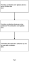
- step S1 conductive cover glasses are provided above a string of solar cells in the solar cell assembly.
- the process of preparing conductive cover glasses can be done by any methods in the conventional art.
- conductive adhesives are provided on top surfaces of the conductive cover glasses.
- each conductive cover glass is provided with two conductive adhesives at two opposite sides on its top surface along the direction of the string (as illustrated in Fig. 1 ).
- the conductive adhesives may be directly attached to the top surfaces.
- step S3 one or more connectors (such as wire conductors) are provided to connect the conductive adhesives such that the conductive cover glasses are connected in series to form a string of conductive cover glasses.
- each pair of two adjacent conductive cover glasses is provided with a separate connector.
- each connector has two ends disposed at two adjacent conductive cover glasses, respectively.
- the conductive adhesives may be directly attached to the top surfaces of the conductive cover glasses.
- the conductive cover glasses are connected in series by the conductive adhesives and the one or more connectors.
- the method may include repeating the steps S2 and S3 once for each pair of adjacent conductive cover glasses or repeating the steps S2 and S3 once for a plurality of pairs of adjacent conductive cover glasses.
- the method may also perform the step S2 for all of the conductive cover glasses before performing the step S3 for all of the conductive adhesives.
- the conductive adhesives may be formed of different shapes than the circular shapes illustrated in Figs. 1 to 4 .
- the conductive adhesives connected by a connector may be formed of different shapes. Thereby, the direction of the string may be easily recognized.
- the conductive adhesive at an end of the string (namely, end conductive adhesive 23) may have a different shape than the remaining conductive adhesives in the string. Thereby, the end conductive adhesive 23 for connection to a terminal and ground can be easily recognized.
- the connectors may be a rectangular wire, a metal strip, a metal band, or the like for connecting one conductive adhesive to another conductive adhesive or to a terminal.
- the solar cell assembly may include other aspects or elements (such as antireflection coating, texturing of surfaces, encapsulation, etc.) for implementation of a solar cell assembly.
Landscapes
- Photovoltaic Devices (AREA)
Abstract
The invention relates to a solar cell assembly including a string of conductive cover glasses corresponding to a string of solar cells. The string of conductive cover glasses each have a top surface facing away with its conductive side from the respective solar cell. Conductive adhesives are disposed on the top surfaces of the conductive cover glasses. One or more connectors, such as wire conductors, are provided to connect the conductive adhesives such that the string of conductive cover glasses are connected in series. Thereby, the conductive cover glasses can be easily connected to each other and the grounding network of the solar cell assembly can be simplified.
Description
- The present disclosure relates to a solar cell assembly. Particularly, the present disclosure relates to a solar cell assembly for space use and a method of connecting conductive cover glasses of the solar cell assembly.
- A solar cell assembly typically includes a cover glass disposed above a solar cell to protect the solar cell. For space use, standard very low conductive cover glasses would be charged up by bombardments of charged particles.
- To avoid the build-up of charges, conductive cover glasses (such as Indium titanium oxide, ITO, glasses) are used as cover glasses. These conductive cover glasses exhibit a conductive surface for discharging the charges.
-
EP 2372784 A1 relates to a multi-junction solar cell with an amount of pn-junctions stacked on top of each other. Therein, a conductive or antistatic coating is provided at the cell edge (namely, the edge of a solar cell facing another solar cell) so as to connect the conductive surface of the cover glass on one side of the solar cell to the rear side metallization on the opposite side of the solar cell. -
EP 2546889 A1 relates to a solar cell assembly of such solar cells and to a method of manufacturing a solar cell assembly. Therein, the cover glass of a solar cell is connected to a contact pad of an adjacent solar cell by a conductive adhesive, which attaches one end of an interconnector to the metallized sidewall of the cover glass. The other end of the interconnector is connected to the contact pad of the adjacent solar cell. Thereby, the cover glass of the solar cell can be grounded. - The conventional methods are, nonetheless, not ideal for connecting and grounding the conductive surfaces of the cover glasses. Specifically, the method of
EP 2372784 A1 requires a mesa groove within the solar cell separating the active cell from the conductive or antistatic coating and thus additional space for the mesa groove between the solar cells. The method ofEP 2546889 A1 utilizes an interconnector and contact pads on the solar cells for connecting the cover glasses and thus requires additional space and components on the solar cells. Therefore, in the conventional art, additional space and components in the solar cell are needed for connecting and grounding the conductive surfaces of the cover glasses. Such additional space and components, in turn, require complex and costly manufacturing processes. Moreover, since the grounding network in conventional art is connected to the sidewall or edge of the cover glass, the conventional methods have to deal with the risk of impacting the active cell area of the solar cell. - Therefore, there has been a problem of providing a simple, cost-efficient, and fast method for connecting the conductive cover glasses of the solar cell assembly for grounding.
- An object of the present disclosure is thus to provide a solar cell assembly with an improved connection for grounding the conductive cover glasses and a method of connecting the conductive cover glasses of a solar cell assembly. According to the present disclosure, a solar cell assembly and a method are set forth in independent claims. Preferred embodiments are defined in dependent claims.
- In an aspect, the present disclosure provides a solar cell assembly comprising a first solar cell, a first conductive cover glass, a second solar cell, and a second conductive cover glass. The first conductive cover glass is disposed above the first solar cell and has a top surface facing away from the first solar cell. The second conductive cover glass is disposed above the second solar cell and has a top surface facing away from the second solar cell. A first conductive adhesive is disposed on the top surface of the first conductive cover glass and a second conductive adhesive is disposed on the top surface of the second conductive cover glass. A connector is provided to connect the first conductive adhesive to the second conductive adhesive. The connector may be a wire conductor, a rectangular wire, a metal strip, or a metal band, or the like.
- By the solar cell assembly according to the present disclosure, the first and second conductive adhesives are disposed on the top surfaces of the respective cover glasses and then connected to each other by the connector. This avoids the risk of impacting the active cell areas of the solar cells that are normally exposed at the edge of the solar cells. A protection structure (such as a mesa groove) or an independent contact point for contact pads is no longer required for protecting the active cell areas at the edge of the solar cells. The structure of the solar cell assembly are thus simplified. Moreover, the process of applying conductive adhesives on the top surfaces is simple, fast, cost-efficient. A grounding network achieved by the solar cell assembly according to the present disclosure is thus more robust and safer against electrostatic discharge (ESD) and charge build up.
- In some aspects, the first and second conductive adhesives may be directly attached to the top surfaces of the first and second conductive cover glasses, respectively. Thereby, the process of connecting the cover glasses is simplified.
- In some aspects, the first conductive cover glass and the second conductive cover glass may be transparent conductive glasses. The transparent conductive glasses may be, at least partially, transmissive to the light to be absorbed by the solar cells. Preferably, the transparent conductive glasses may comprise Indium Tin oxide (ITO). The conductive cover glasses may be glasses coated with a conductive transparent material, such as an ITO coating. Thereby, each of the conductive cover glasses provides charge bleeding properties for preventing the build-up of charges if the cover glasses are grounded.
- In some aspects, the solar cell assembly may include a string of solar cells connected in series and a string of conductive cover glasses corresponding to the string of solar cells. In some aspects, a plurality of solar cell assemblies are connected in series to form a string. The string of conductive cover glasses are each disposed above a respective solar cell of the string of solar cells and each have a top surface facing away from the respective solar cell. Conductive adhesives are provided on the top surfaces of the conductive cover glasses and one or more connectors are provided to connect the conductive adhesives such that the string of conductive cover glasses are connected in series. Thereby, the solar cell assembly includes a simple, cost-efficient, more robust, and safer grounding network for the string of cover glasses. The mass of the cover glass grounding network is also reduced. The one or more connectors may be wire conductors.
- In some aspects, the string of conductive cover glasses may each have two conductive adhesives on the respective top surfaces. The one or more connectors may each have two ends disposed at one conductive cover glass and an adjacent conductive cover glass, respectively, wherein the one conductive cover glass and the adjacent conductive cover glass are adjacent to each other in the string of the conductive cover glasses. By providing two conductive adhesives on each conductive cover glass and one connector (such as a wire conductor) between two adjacent conductive cover glasses, the string can be easily connected by performing connection between two adjacent conductive cover glasses one at a time or all together, without affecting connection between other conductive cover glasses. It is thus possible to further simplify and expedite the process of connecting the string of conductive cover glasses. Further, the volume of adhesives for connection can be reduced by applying two conductive adhesives on each conductive cover glass, as compared to the volume of adhesives used to cover the solar cell edges. This further improves the safety of the solar cell assembly since the adhesives may deteriorate and crack due to, for example, normal or deep-temperature thermal cycling. Also the number of adhesive surface interface is low as there is only the cover glass to adhesive interface of potential criticality whereas the connector or wire conductor can be embedded partially or fully into the adhesive for additional safety.
- In some aspects, the two conductive adhesives of the respective top surface may be disposed at two opposite sides along a direction of the string of the conductive cover glasses. Meanwhile, the two ends of the one or more connectors are fixed to conductive adhesives at respective sides of the adjacent conductive cover glass and the one conductive cover glass facing each other along the direction of the string of the conductive cover glass. Thereby, the connector extends between the sides of the two adjacent conductive cover glasses that are facing each other along the direction of the string of the conductive cover glasses. The length of the connector can thus be shortened, which not only simplifies the connection between two adjacent conductive cover glasses but also increases the space for simultaneously connecting multiple pairs of two adjacent conductive cover glasses.
- In some aspects, the string of conductive cover glasses may have an end conductive cover glass at one end of the string. The top surface of the end conductive cover glass may be connected to a terminal by an end conductive adhesive on the top surface of the end conductive cover glass and an end connector connecting the end conductive adhesive to the terminal. The terminal may be adapted to be connected to ground. Thereby, the solar cell assembly may be easily connected to ground for achieving ESD safety by connecting the terminal to ground.
- In some aspects, the end connector may be welded to the terminal.
- In some aspects, the solar cell assembly may have a front side, on which the string of conductive cover glasses are disposed above the string of solar cells, and a rear side opposite to the front side. The terminal may be connected to the rear conductive cover glass on the rear side. The solar cell assembly may further include a cover glass bleeder resistor on the rear side.
- In some aspects, the string of conductive cover glasses have another end conductive cover glass at the other end of the string. The top surface of the another end conductive cover glass may be connected to another terminal by another end conductive adhesive on the top surface of the another end conductive cover glass and another end connector connecting the another end conductive adhesive to the another terminal. The another terminal may be adapted to be connected to ground. Thereby, the solar cell assembly may be connected to ground from two sides. The grounding from two sides is a major advantage of the invention as the design is single point failure tolerant.
- In another aspect, the present disclosure provides a method of connecting a string of conductive cover glasses of a solar cell assembly. The method includes providing conductive adhesives on top surfaces of the conductive cover glasses and connecting the conductive adhesives by one or more connectors. The top surfaces of the conductive cover glasses face away from solar cells disposed below the conductive cover glasses.
- In some aspects, the conductive adhesives may be directly attached to the top surfaces of the conductive cover glasses in the step of providing conductive adhesives.
- In some aspect, the string of conductive cover glasses may each have two conductive adhesives disposed on the respective top surfaces. The one or more connectors may each have two ends disposed on one conductive cover glass and an adjacent conductive cover glass, respectively. The adjacent conductive cover glass and the one conductive cover glass are adjacent to each other in the string of conductive cover glasses.
- In the drawings, which are not necessarily drawn to scale, like numerals may reference similar components in different figures. The shapes of elements illustrated in the drawings are not intended to limit the embodiments or the scope of the present disclosure, unless explicitly specified. The drawings illustrate various embodiments of the present disclosure.
-
Fig. 1 is a diagram illustrating a top view of a portion of a solar cell assembly according to the present disclosure. -
Fig. 2 is a diagram illustrating an enlarged view of the area C inFig. 1 . -
Fig. 3 is a diagram illustrating the grounding network of the solar cell assembly according to the present disclosure. -
Fig. 4 is a diagram illustrating a cover glass bleed resistor on the panel rear side with wire connections. -
Fig. 5 is a diagram illustrating a flowchart of a method according to the present disclosure. - In the present disclosure, when an element, such as a layer, a region, or a substrate, is referred to as being on, connected to, connected to, coupled to, or attached to another element, it may be directly on, connected, coupled, or attached to the other element, or one or more intervening elements may be present. In contrast, when an element is referred to as being directly on, directly connected to, directly coupled to, or directly attached to another element or layer, there are no intervening elements or layers present. Although the terms directly on, directly connected to, directly coupled to, or directly attached to may not be used throughout the detailed description, elements that are shown (e.g., in the drawings) as being directly on, directly connected, directly coupled, or directly attached can be referred to as such.
- Spatially relative terms (e.g., on, before, top, bottom, and so forth) are intended to encompass different orientations of the device in use or operation in addition to the orientation depicted in the figures and to be interpreted together with the relevant context.
- The term solar cell assembly denotes a spatial arrangement of a plurality of solar cells or cover integrated cells, i.e. solar cells equipped with interconnector and cover glass.
- Embodiments according to the present disclosure will be explained in the following with reference to the figures.
-
Fig. 1 illustrates a top view of a portion of a solar cell assembly. In the middle ofFig. 1 , threeconductive cover glasses 11 to 13 are illustrated. The threeconductive cover glasses 11 to 13 forms a string of conductive cover glasses or forms a part of a string of conductive cover glasses in a direction A. On the left and right sides of the threeconductive cover glasses 11 to 13, the solar cell assembly also includes a left string of conductive cover glasses and a right string of conductive cover glasses in the direction A. Each of the conductive cover glasses has a top surface, which is conductive, as shown in the top view. As can be seen inFig. 1 , the conductive cover glasses are spaced from each other by a gap. - Through not illustrated in the drawings, the solar cell assembly has solar cells corresponding to conductive cover glasses, respectively. Specifically, the conductive cover glasses are disposed above the respective solar cells in the direction normal to the top surface for protecting the respective solar cells. More specifically, the solar cell assembly has strings of solar cells and strings of conductive cover glasses. Each string of conductive cover glasses connected in series may be disposed above a string of solar cells connected in series so that the conductive cover glasses face the solar cells, respectively. In some embodiments, different strings of conductive cover glasses can be connected for simplifying the manufacturing process, which also shows the flexibility of the solar cell assembly according to the present disclosure.
- The conductive cover glasses may be transparent conductive glasses, which are, at least partially, transmissive to the light to be absorbed by the solar cells disposed below the conductive. Preferably, the transparent conductive cover glasses comprise Indium Tin oxide (ITO). The conductive cover glasses may be glasses coated with a conductive transparent material, such as an ITO coating. Thereby, each of the conductive cover glasses provides charge bleeding properties for preventing the build-up of charges resulting from charged particles in space.
- Referring again to
Fig. 1 , the adjacent two conductive cover glasses in a string of conductive cover glasses are connected to each other through their top surfaces. InFig. 1 , the firstconductive cover glass 11 is connected to the secondconductive cover glass 12, which is then connected to the thirdconductive cover glass 13 to form a string or a part of a string of conductive cover glasses. As can be seen on the right side of the first, second, and thirdconductive cover glasses Fig. 1 , three conductive cover glasses are also connected in series to form a string or a part of a string of conductive cover glasses. - Specifically, two adjacent conductive cover glasses in a string are connected to each other by a
connector 2. Theconnector 2 includes a wire conductor 22 (as a connector) connecting twoconductive adhesives 21 disposed on the top surfaces of the two adjacent cover glasses. The wire conductor according to the present disclosure may comply with American Wire Gauge (AWG) 40, or other sizes. The conductive adhesives according to the present disclosure may be the conductor under the tradename NuSil CV1500. - Referring to
Fig. 2 , which illustrates an enlarged view of the area C inFig. 1 , theconductive adhesives 21 are disposed on the top surfaces of the firstconductive cover glass 11 and the secondconductive cover glass 12. In particular, theconductive adhesives 21 are directly applied onto the top surfaces of the firstconductive cover glass 11 and the secondconductive cover glass 12. Awire conductor 22 is then attached (and/or embedded partly or fully into) to theconductive adhesives 21. Thereafter, theconductive adhesives 21 are cured and fixed, together with thewire conductor 22, on the top surfaces of the firstconductive cover glass 11 and the secondconductive cover glass 12. Theconnector 2 is thus formed of the wire conductor and the twoconductive adhesives 21 on the firstconductive cover glass 11 and the secondconductive cover glass 12. - As a result, an electrical connection is accomplished between the first
conductive cover glass 11 and the secondconductive cover glass 12. In other words, the firstconductive cover glass 11 is electrically connected to the secondconductive cover glass 12 by theconnector 2. - Referring to
Fig. 1 again, aconnector 2 is provided to connect the secondconductive cover glass 12 to the thirdconductive cover glass 13. The first, second, and thirdconductive cover glasses Fig. 1 . - By connecting the conductive cover glasses through their top surfaces according to the present disclosure, the conductive cover glasses can be easily connected to each other for grounding. This avoids the risk of impacting the active cell areas of the solar cells that are normally exposed at the edge of the solar cells. The process of connecting the conductive cover glasses can also be simplified, faster and more cost-efficient, since the top surfaces of the conductive cover glasses offer a large area of implementing the connection and protection for the active cells below the conductive cover glasses. A grounding network of the solar cell assembly according to the present disclosure is thus more robust and safer against electrostatic discharge (ESD), and allows for charge reduction.
- As shown in
Fig. 1 , each conductive cover glass has twoconductive adhesives 21 on its top surface, one for connection with an upstream conductive cover glass in the direction A and the other for connection with a downstream conductive cover glass in the direction A. As also shown inFig. 1 , eachwire conductor 22 has two ends on one conductive cover glass and an adjacent conductive cover glass, respectively. For example, two ends of awire conductor 22 are disposed at the firstconductive cover glass 11 and the secondconductive cover glass 12, respectively. - By providing two conductive adhesives on each conductive cover glass and one wire conductor between two adjacent conductive cover glasses, the string can be easily connected by performing connection between two adjacent conductive cover glasses one at a time or all together, without affecting connection between other conductive cover glasses. For example, the
connector 2 between the firstconductive cover glass 11 and the secondconductive cover glass 12 and theconnector 2 between the secondconductive cover glass 12 and the thirdconductive cover glass 13 can be prepared at the same time without affecting each other. It is thus possible to further simplify and expedite the process of connecting the string of conductive cover glass. - In particular, the two
conductive adhesives 21 on the same conductive cover glass are provided at two opposite sides along the direction A of the string of the conductive cover glasses. Thewire conductor 22 is fixed to twoconductive adhesives 21 at respective sides of two adjacent conductive cover glasses facing each other along the direction A of the string. More specifically, inFig. 1 , the upper side of the secondconductive cover glass 12 along the direction A faces the lower side of the firstconductive cover glass 11. Thewire connector 22 is fixed to twoconductive adhesives 21 at the upper side of the secondconductive cover glass 12 and the lower side of the firstconductive cover glass 11, respectively. - By fixing the wire conductor at respective sides of two adjacent conductive cover glasses facing each other, the length of the wire conductor can be further shortened, which not only simplifies the connection between two adjacent conductive cover glasses but also increases the space for simultaneously connecting multiple pairs of two adjacent conductive cover glasses.
- Referring to
Fig. 3 , a grounding network of the solar cell assembly according to the present disclosure will be explained in the following. - A string of
conductive cover glasses 10 to 1n is illustrated inFig. 3 . The string has an endconductive cover glass 10 at one end and another endconductive cover glass 1n at the other end. On the top surface of the endconductive cover glass 10, an end conductive adhesive 23 provided at the upper side is connected by an end wire conductor 24 (as an end connector) to a (small)terminal 3. Theterminal 3 can then be connected to ground. InFig. 3 , theterminal 3 next to the endconductive cover glass 10 is connected to an optional cover glass bleeder resistor on the panel rear side. - At the other end of the string, another end conductive adhesive 23 provided at the lower side of the another end
conductive cover glass 1n is connected to anotherterminal 3 by another end wire conductor 24 (as another end connector). The anotherterminal 3 can then be connected to ground. Thereby, the solar cell assembly may be connected to ground from two sides of the string. The grounding from two sides is a major advantage of the invention as the design is single point failure tolerant. - Referring to
Fig. 4 , a cover glass bleed resistor is provided on the panel rear side with wire connections. The cover glass bleed resistor is located on and glued to the back/rear side of the solar cell assembly. The cover glass bleed resistor has several glue points and welding terminals for providing redundancy. By providing such cover glass bleed resistor, no high-standard and expensive components (such as EEE parts) are required for grounding the solar cell assembly. The cover glass bleed resistor is also more robust and provides bleeding the string ends on the front side of the solar cell assembly. Further, the cover glass bleed resistor can ground or soft ground other components. The cover glass bleed resistor can be located onto the panel rear side to safe place on the panel front side for solar cells. The connection is realized by standard solar array wires (with electrical insulation). These wires are welded on one side to a welding terminal of the cover glass bleed resistor and on the other side to the welding terminals of the cover glass string ends. This can be done in redundant ways. - A method of connecting a string of conductive cover glasses of a solar cell assembly will be described in the following with reference to
Fig. 5 . - In step S1, conductive cover glasses are provided above a string of solar cells in the solar cell assembly. The process of preparing conductive cover glasses can be done by any methods in the conventional art.
- In step S2, conductive adhesives are provided on top surfaces of the conductive cover glasses. Preferably, each conductive cover glass is provided with two conductive adhesives at two opposite sides on its top surface along the direction of the string (as illustrated in
Fig. 1 ). The conductive adhesives may be directly attached to the top surfaces. - In step S3, one or more connectors (such as wire conductors) are provided to connect the conductive adhesives such that the conductive cover glasses are connected in series to form a string of conductive cover glasses. Preferably, each pair of two adjacent conductive cover glasses is provided with a separate connector. Namely, each connector has two ends disposed at two adjacent conductive cover glasses, respectively. The conductive adhesives may be directly attached to the top surfaces of the conductive cover glasses.
- As a result, the conductive cover glasses are connected in series by the conductive adhesives and the one or more connectors.
- The method may include repeating the steps S2 and S3 once for each pair of adjacent conductive cover glasses or repeating the steps S2 and S3 once for a plurality of pairs of adjacent conductive cover glasses. The method may also perform the step S2 for all of the conductive cover glasses before performing the step S3 for all of the conductive adhesives.
- While specific embodiments are described above with reference to the drawings, various modifications are covered by the present disclosure. In the following, some modifications of the present disclosure will be described by discussing the differences from the embodiments described above.
- In one modification, the conductive adhesives may be formed of different shapes than the circular shapes illustrated in
Figs. 1 to 4 . - In one modification, the conductive adhesives connected by a connector may be formed of different shapes. Thereby, the direction of the string may be easily recognized.
- In one modification, the conductive adhesive at an end of the string (namely, end conductive adhesive 23) may have a different shape than the remaining conductive adhesives in the string. Thereby, the end
conductive adhesive 23 for connection to a terminal and ground can be easily recognized. - In one modification, the connectors may be a rectangular wire, a metal strip, a metal band, or the like for connecting one conductive adhesive to another conductive adhesive or to a terminal.
- The above embodiments and modifications are not intended to limit the scope of the present invention. Various implementations are covered by the scope of the present invention defined by the appended claims.
- The above describes some aspects or elements of the solar cell assembly, with which the present disclosure is concerned. A person skilled in the art would understand from the common general knowledge that the solar cell assembly may include other aspects or elements (such as antireflection coating, texturing of surfaces, encapsulation, etc.) for implementation of a solar cell assembly.
Claims (15)
- A solar cell assembly, comprisinga first solar cell,a first conductive cover glass (11) disposed above the first solar cell and having a top surface facing away from the first solar cell,a first conductive adhesive (21) on the top surface of the first conductive cover glass (11),a second solar cell,a second conductive cover glass (12) disposed above the second solar cell and having a top surface facing away from the second solar cell,a second conductive adhesive (21) on the top surface of the second conductive cover glass (12), anda connector (22) connecting the first conductive adhesive to the second conductive adhesive.
- The solar cell assembly according to claim 1, wherein the first and second conductive adhesives (21) are directly attached to the top surfaces of the first and second conductive cover glasses (11, 12), respectively.
- The solar cell assembly according to claim 1 or 2, wherein the first conductive cover glass (11) and the second conductive cover glass (12) are transparent conductive glasses and/or comprise Indium Tin oxide, ITO.
- The solar cell assembly according to any of claims 1 to 3, the connector (22) is a wire conductor connecting the first conductive adhesive to the second conductive adhesive.
- The solar cell assembly according to any of claims 1 to 4, further comprising:a string of solar cells connected in series and including the first and second solar cells,a string of conductive cover glasses (10 to 1n) including the first and second conductive cover glasses (11, 12), each of the conductive cover glasses (10 to 1n) being disposed above a respective solar cell of the string of solar cells and having a top surface facing away from the respective solar cell,conductive adhesives (21) on the top surfaces of the conductive cover glasses (10 to 1n),one or more connectors (22) connecting the conductive adhesives (21) such that the string of conductive cover glasses (10 to 1n) are connected in series.
- The solar cell assembly according to claim 5,wherein the string of conductive cover glasses (10 to 1n) each have two conductive adhesives (21) on the respective top surfaces,wherein the one or more connectors (22) each have two ends disposed at one conductive cover glass and an adjacent conductive cover glass, respectively, andwherein the adjacent conductive cover glass and the one conductive cover glass are adjacent to each other in the string of conductive cover glasses (10 to 1n).
- The solar cell assembly according to claim 6,wherein the two conductive adhesives (21) on the respective top surface are disposed at two opposite sides along a direction (A) of the string of the conductive cover glasses (10 to 1n), andwherein the two ends of the one or more connectors (22) are fixed to conductive adhesives (21) at respective sides of the adjacent conductive cover glass and the one conductive cover glass facing each other along the direction (A) of the string of the conductive cover glasses (10 to 1n).
- The solar cell assembly according to any of claims 5 to 7,wherein the string of conductive cover glasses (10 to 1n) have an end conductive cover glass (10) at one end of the string,wherein the top surface of the end conductive cover glass (10) is connected to a terminal (3) by an end conductive adhesive (23) on the top surface of the end conductive cover glass (10) and an end connectors(24) connecting the end conductive adhesive (23) to the terminal (3), andwherein the terminal (3) is adapted to be connected to ground (GND).
- The solar cell assembly according to claim 8, wherein the end connectors (24) is welded to the terminal (3).
- The solar cell assembly according to claim 8 or 9,wherein the solar cell assembly has a front side, on which the string of conductive cover glasses are disposed above the string of solar cells, and a rear side opposite to the front side, andwherein the terminal (3) is connected to a rear conductive cover glass on the rear side.
- The solar cell assembly according to claim 10, further comprising a cover glass bleeder resistor on the rear side.
- The solar cell assembly according to any of claim 8 to 11,wherein the string of conductive cover glasses have another end conductive cover glass (1n) at the other end of the string,wherein the top surface of the another end conductive cover glass (1n) is connected to another terminal (3) by another end conductive adhesive (23) on the top surface of the another end conductive cover glass (1n) and another end connectors (24) connecting the another end conductive adhesive (23) to the another terminal (3),wherein the another terminal (3) is adapted to be connected to ground (GND).
- A method of connecting conductive cover glasses of a solar cell assembly into a string, comprisingproviding conductive adhesives on top surfaces of the conductive cover glasses, wherein the top surfaces of the conductive cover glasses face away from solar cells disposed below the conductive cover glasses, andconnecting the conductive adhesives by one or more connectors.
- The method according to claim 13, wherein the conductive adhesives are directly attached to the top surfaces of the conductive cover glasses.
- The method according to claim 13 or 14,wherein the string of conductive cover glasses each have two conductive adhesives disposed on the respective top surfaces, andwherein the one or more connectors each have two ends disposed on one conductive cover glass and an adjacent conductive cover glass, respectively,wherein the adjacent conductive cover glass and the one conductive cover glass are adjacent to each other in the string of conductive cover glasses.
Priority Applications (1)
| Application Number | Priority Date | Filing Date | Title |
|---|---|---|---|
| EP23176102.4A EP4471876A1 (en) | 2023-05-30 | 2023-05-30 | Solar cell assembly and method of connecting conductive cover glasses of the same |
Applications Claiming Priority (1)
| Application Number | Priority Date | Filing Date | Title |
|---|---|---|---|
| EP23176102.4A EP4471876A1 (en) | 2023-05-30 | 2023-05-30 | Solar cell assembly and method of connecting conductive cover glasses of the same |
Publications (1)
| Publication Number | Publication Date |
|---|---|
| EP4471876A1 true EP4471876A1 (en) | 2024-12-04 |
Family
ID=86609685
Family Applications (1)
| Application Number | Title | Priority Date | Filing Date |
|---|---|---|---|
| EP23176102.4A Pending EP4471876A1 (en) | 2023-05-30 | 2023-05-30 | Solar cell assembly and method of connecting conductive cover glasses of the same |
Country Status (1)
| Country | Link |
|---|---|
| EP (1) | EP4471876A1 (en) |
Citations (5)
| Publication number | Priority date | Publication date | Assignee | Title |
|---|---|---|---|---|
| DE3617675A1 (en) * | 1985-06-15 | 1986-12-18 | Licentia Patent-Verwaltungs-Gmbh, 6000 Frankfurt | Device on solar generators for preventing static charging |
| US5919316A (en) * | 1997-06-27 | 1999-07-06 | The United States Of America As Represented By The Secretary Of The Air Force | Spacecraft solar array design to control differential charging |
| JP2000228530A (en) * | 1999-02-05 | 2000-08-15 | Toshiba Corp | Solar panel |
| EP2372784A1 (en) | 2010-03-29 | 2011-10-05 | Astrium GmbH | Solar cell, especially a multi-junction solar cell, for space applications |
| EP2546889A1 (en) | 2011-07-12 | 2013-01-16 | Astrium GmbH | Solar cell and solar cell assembly |
-
2023
- 2023-05-30 EP EP23176102.4A patent/EP4471876A1/en active Pending
Patent Citations (5)
| Publication number | Priority date | Publication date | Assignee | Title |
|---|---|---|---|---|
| DE3617675A1 (en) * | 1985-06-15 | 1986-12-18 | Licentia Patent-Verwaltungs-Gmbh, 6000 Frankfurt | Device on solar generators for preventing static charging |
| US5919316A (en) * | 1997-06-27 | 1999-07-06 | The United States Of America As Represented By The Secretary Of The Air Force | Spacecraft solar array design to control differential charging |
| JP2000228530A (en) * | 1999-02-05 | 2000-08-15 | Toshiba Corp | Solar panel |
| EP2372784A1 (en) | 2010-03-29 | 2011-10-05 | Astrium GmbH | Solar cell, especially a multi-junction solar cell, for space applications |
| EP2546889A1 (en) | 2011-07-12 | 2013-01-16 | Astrium GmbH | Solar cell and solar cell assembly |
Non-Patent Citations (2)
| Title |
|---|
| KOCH J W ED - LANDEAU J: "A LOW COST ANTICHARGING CONNECTION SYSTEM FOR SOLAR GENERATORS AND ITS APPLICATION ON ASPERA SOLAR ARRAY", EUROPEAN SPACE POWER. MADRID, OCT. 2 - 6, 1989; [PROCEEDINGS OF THE EUROPEAN SPACE POWER CONFERENCE], NOORDWIJK, ESA PUBLICATIONS, NL, vol. 2, 2 October 1989 (1989-10-02), pages 587 - 590, XP000173834 * |
| TOYODA K ET AL: "ESD Ground Test of Solar Array Coupons for a Greenhouse Gases Observing Satellite in PEO", IEEE TRANSACTIONS ON PLASMA SCIENCE, IEEE SERVICE CENTER, PISCATAWAY, NJ, US, vol. 36, no. 5, 31 October 2008 (2008-10-31), pages 2413 - 2424, XP011237248, ISSN: 0093-3813, DOI: 10.1109/TPS.2008.2002823 * |
Similar Documents
| Publication | Publication Date | Title |
|---|---|---|
| EP2897179B1 (en) | Solar cell module | |
| US10896984B2 (en) | Solar cell module | |
| US5919316A (en) | Spacecraft solar array design to control differential charging | |
| JP5547248B2 (en) | Interconnection of solar cells in solar cell modules | |
| EP1801889B1 (en) | Thin-film solar cell module and method of manufacturing the same | |
| US12183840B2 (en) | Solar cell and solar cell module | |
| EP1246249A2 (en) | Thin-film solar cell module of see-through type | |
| EP2372784B1 (en) | Solar cell, especially a multi-junction solar cell, for space applications | |
| US6194651B1 (en) | Electrostatic discharge for solar cell | |
| US20160181454A1 (en) | Solar cell module and method for manufacturing the same | |
| EP4383354A1 (en) | Shingled solar module with ribbon interconnect | |
| CN114883439B (en) | Solar cell side surface interconnects | |
| EP3288086A1 (en) | Solar cell module and method for manufacturing the same | |
| JPWO2018116643A1 (en) | Solar cell module and method of manufacturing the same | |
| US12615852B2 (en) | Solar module with optimized interconnection and method of manufacturing the same | |
| US11398439B2 (en) | Display panel and display device | |
| US20240274739A1 (en) | Photovoltaic string | |
| JP3259771B2 (en) | Plasma display panel | |
| US20250221058A1 (en) | Protected interconnects for low stress solar cell shingling and improved aesthetics | |
| KR20240125673A (en) | solar module | |
| KR101823601B1 (en) | Solar cell module | |
| TW202341506A (en) | An electrode assembly | |
| CN118043975A (en) | Solar cell equipment and solar cell modules | |
| CN119968944A (en) | Solar cell modules |
Legal Events
| Date | Code | Title | Description |
|---|---|---|---|
| PUAI | Public reference made under article 153(3) epc to a published international application that has entered the european phase |
Free format text: ORIGINAL CODE: 0009012 |
|
| STAA | Information on the status of an ep patent application or granted ep patent |
Free format text: STATUS: REQUEST FOR EXAMINATION WAS MADE |
|
| 17P | Request for examination filed |
Effective date: 20240709 |
|
| AK | Designated contracting states |
Kind code of ref document: A1 Designated state(s): AL AT BE BG CH CY CZ DE DK EE ES FI FR GB GR HR HU IE IS IT LI LT LU LV MC ME MK MT NL NO PL PT RO RS SE SI SK SM TR |