EP4471759A1 - Method for designing formable additively manufactured acoustic liners - Google Patents
Method for designing formable additively manufactured acoustic liners Download PDFInfo
- Publication number
- EP4471759A1 EP4471759A1 EP24178095.6A EP24178095A EP4471759A1 EP 4471759 A1 EP4471759 A1 EP 4471759A1 EP 24178095 A EP24178095 A EP 24178095A EP 4471759 A1 EP4471759 A1 EP 4471759A1
- Authority
- EP
- European Patent Office
- Prior art keywords
- walls
- lengthwise
- widthwise
- honeycomb core
- wall
- Prior art date
- Legal status (The legal status is an assumption and is not a legal conclusion. Google has not performed a legal analysis and makes no representation as to the accuracy of the status listed.)
- Pending
Links
Images


Classifications
-
- G—PHYSICS
- G10—MUSICAL INSTRUMENTS; ACOUSTICS
- G10K—SOUND-PRODUCING DEVICES; METHODS OR DEVICES FOR PROTECTING AGAINST, OR FOR DAMPING, NOISE OR OTHER ACOUSTIC WAVES IN GENERAL; ACOUSTICS NOT OTHERWISE PROVIDED FOR
- G10K11/00—Methods or devices for transmitting, conducting or directing sound in general; Methods or devices for protecting against, or for damping, noise or other acoustic waves in general
- G10K11/16—Methods or devices for protecting against, or for damping, noise or other acoustic waves in general
- G10K11/172—Methods or devices for protecting against, or for damping, noise or other acoustic waves in general using resonance effects
-
- F—MECHANICAL ENGINEERING; LIGHTING; HEATING; WEAPONS; BLASTING
- F02—COMBUSTION ENGINES; HOT-GAS OR COMBUSTION-PRODUCT ENGINE PLANTS
- F02C—GAS-TURBINE PLANTS; AIR INTAKES FOR JET-PROPULSION PLANTS; CONTROLLING FUEL SUPPLY IN AIR-BREATHING JET-PROPULSION PLANTS
- F02C7/00—Features, components parts, details or accessories, not provided for in, or of interest apart form groups F02C1/00 - F02C6/00; Air intakes for jet-propulsion plants
- F02C7/04—Air intakes for gas-turbine plants or jet-propulsion plants
- F02C7/045—Air intakes for gas-turbine plants or jet-propulsion plants having provisions for noise suppression
-
- B—PERFORMING OPERATIONS; TRANSPORTING
- B22—CASTING; POWDER METALLURGY
- B22F—WORKING METALLIC POWDER; MANUFACTURE OF ARTICLES FROM METALLIC POWDER; MAKING METALLIC POWDER; APPARATUS OR DEVICES SPECIALLY ADAPTED FOR METALLIC POWDER
- B22F10/00—Additive manufacturing of workpieces or articles from metallic powder
- B22F10/60—Treatment of workpieces or articles after build-up
- B22F10/64—Treatment of workpieces or articles after build-up by thermal means
-
- B—PERFORMING OPERATIONS; TRANSPORTING
- B22—CASTING; POWDER METALLURGY
- B22F—WORKING METALLIC POWDER; MANUFACTURE OF ARTICLES FROM METALLIC POWDER; MAKING METALLIC POWDER; APPARATUS OR DEVICES SPECIALLY ADAPTED FOR METALLIC POWDER
- B22F10/00—Additive manufacturing of workpieces or articles from metallic powder
- B22F10/60—Treatment of workpieces or articles after build-up
- B22F10/66—Treatment of workpieces or articles after build-up by mechanical means
-
- B—PERFORMING OPERATIONS; TRANSPORTING
- B22—CASTING; POWDER METALLURGY
- B22F—WORKING METALLIC POWDER; MANUFACTURE OF ARTICLES FROM METALLIC POWDER; MAKING METALLIC POWDER; APPARATUS OR DEVICES SPECIALLY ADAPTED FOR METALLIC POWDER
- B22F5/00—Manufacture of workpieces or articles from metallic powder characterised by the special shape of the product
- B22F5/009—Manufacture of workpieces or articles from metallic powder characterised by the special shape of the product of turbine components other than turbine blades
-
- F—MECHANICAL ENGINEERING; LIGHTING; HEATING; WEAPONS; BLASTING
- F02—COMBUSTION ENGINES; HOT-GAS OR COMBUSTION-PRODUCT ENGINE PLANTS
- F02K—JET-PROPULSION PLANTS
- F02K1/00—Plants characterised by the form or arrangement of the jet pipe or nozzle; Jet pipes or nozzles peculiar thereto
- F02K1/78—Other construction of jet pipes
- F02K1/82—Jet pipe walls, e.g. liners
- F02K1/827—Sound absorbing structures or liners
-
- G—PHYSICS
- G10—MUSICAL INSTRUMENTS; ACOUSTICS
- G10K—SOUND-PRODUCING DEVICES; METHODS OR DEVICES FOR PROTECTING AGAINST, OR FOR DAMPING, NOISE OR OTHER ACOUSTIC WAVES IN GENERAL; ACOUSTICS NOT OTHERWISE PROVIDED FOR
- G10K11/00—Methods or devices for transmitting, conducting or directing sound in general; Methods or devices for protecting against, or for damping, noise or other acoustic waves in general
- G10K11/16—Methods or devices for protecting against, or for damping, noise or other acoustic waves in general
- G10K11/162—Selection of materials
- G10K11/168—Plural layers of different materials, e.g. sandwiches
-
- B—PERFORMING OPERATIONS; TRANSPORTING
- B33—ADDITIVE MANUFACTURING TECHNOLOGY
- B33Y—ADDITIVE MANUFACTURING, i.e. MANUFACTURING OF THREE-DIMENSIONAL [3D] OBJECTS BY ADDITIVE DEPOSITION, ADDITIVE AGGLOMERATION OR ADDITIVE LAYERING, e.g. BY 3D PRINTING, STEREOLITHOGRAPHY OR SELECTIVE LASER SINTERING
- B33Y10/00—Processes of additive manufacturing
-
- B—PERFORMING OPERATIONS; TRANSPORTING
- B33—ADDITIVE MANUFACTURING TECHNOLOGY
- B33Y—ADDITIVE MANUFACTURING, i.e. MANUFACTURING OF THREE-DIMENSIONAL [3D] OBJECTS BY ADDITIVE DEPOSITION, ADDITIVE AGGLOMERATION OR ADDITIVE LAYERING, e.g. BY 3D PRINTING, STEREOLITHOGRAPHY OR SELECTIVE LASER SINTERING
- B33Y40/00—Auxiliary operations or equipment, e.g. for material handling
- B33Y40/20—Post-treatment, e.g. curing, coating or polishing
-
- B—PERFORMING OPERATIONS; TRANSPORTING
- B33—ADDITIVE MANUFACTURING TECHNOLOGY
- B33Y—ADDITIVE MANUFACTURING, i.e. MANUFACTURING OF THREE-DIMENSIONAL [3D] OBJECTS BY ADDITIVE DEPOSITION, ADDITIVE AGGLOMERATION OR ADDITIVE LAYERING, e.g. BY 3D PRINTING, STEREOLITHOGRAPHY OR SELECTIVE LASER SINTERING
- B33Y80/00—Products made by additive manufacturing
-
- B—PERFORMING OPERATIONS; TRANSPORTING
- B64—AIRCRAFT; AVIATION; COSMONAUTICS
- B64D—EQUIPMENT FOR FITTING IN OR TO AIRCRAFT; FLIGHT SUITS; PARACHUTES; ARRANGEMENT OR MOUNTING OF POWER PLANTS OR PROPULSION TRANSMISSIONS IN AIRCRAFT
- B64D33/00—Arrangement in aircraft of power plant parts or auxiliaries not otherwise provided for
- B64D33/02—Arrangement in aircraft of power plant parts or auxiliaries not otherwise provided for of combustion air intakes
- B64D2033/0206—Arrangement in aircraft of power plant parts or auxiliaries not otherwise provided for of combustion air intakes comprising noise reduction means, e.g. acoustic liners
-
- F—MECHANICAL ENGINEERING; LIGHTING; HEATING; WEAPONS; BLASTING
- F05—INDEXING SCHEMES RELATING TO ENGINES OR PUMPS IN VARIOUS SUBCLASSES OF CLASSES F01-F04
- F05D—INDEXING SCHEME FOR ASPECTS RELATING TO NON-POSITIVE-DISPLACEMENT MACHINES OR ENGINES, GAS-TURBINES OR JET-PROPULSION PLANTS
- F05D2260/00—Function
- F05D2260/96—Preventing, counteracting or reducing vibration or noise
Definitions
- This disclosure relates to gas turbine engines in aircraft, and in particular, to an acoustic liner for reducing emitted noise propagating through a duct of the gas turbine engine.
- a gas turbine engine of the aircraft generates noise that requires attenuation and control.
- Acoustic liners are provided within a flow duct of the gas turbine engine to attenuate the noise generated by the gas turbine engine.
- Current acoustic liners generally include a honeycomb core and a face sheet attached to the honeycomb core.
- the honeycomb core is generally made out of aluminum and the face sheet is typically made out of fiberglass or aluminum.
- the honeycomb core is cut to shape while in a flat sheet then expanded out to form a 3D volume.
- a drawback of this process is that honeycomb geometries must be fairly simple and straight forward to produce.
- AM polymers allows for the creation of acoustic liners that have more complex geometry that may result in improved acoustic characteristics, lower weight, and less drag.
- AM parts must be printed in discrete, flat layers, while acoustic liners in an engine are often curved around a center axis the engine.
- Printing AM acoustic liners in their curved shape leads to all sorts of drawbacks such as excess material used for support, rough surface finishes on the flow facing face sheet, and constraints placed on cell geometry due to cell orientation.
- An acoustic liner panel includes a honeycomb core with a plurality of lengthwise walls extending in a lengthwise direction.
- Each lengthwise wall of the plurality of lengthwise walls includes a base edge extending straight in the lengthwise direction and a top edge extending in a wavy pattern in the lengthwise direction, with the top edge being greater in length than the base edge.
- the honeycomb core also includes a plurality of widthwise walls extending in a widthwise direction.
- the plurality of widthwise walls intersects the plurality of lengthwise walls.
- Each widthwise wall of the plurality of widthwise walls includes a base edge extending straight in the widthwise direction and a top edge extending in a wavy pattern in the widthwise direction, with the top edge being greater in length than the base edge.
- a plurality of cells is formed by the plurality of lengthwise walls and the plurality of widthwise walls.
- a flat face sheet connected to the base edge of each lengthwise wall of the plurality of lengthwise walls and connected to the base edge of each widthwise wall of the plurality of widthwise walls.
- the wavy pattern of the top edge of each lengthwise wall of the plurality of lengthwise walls includes a wavelength extending in the lengthwise direction and an amplitude extending in the widthwise direction
- the top edge of each widthwise wall of the plurality of widthwise walls includes a wavelength extending in the widthwise direction and an amplitude extending in the widthwise direction
- the wavy pattern of the top edge of each lengthwise wall of the plurality of lengthwise walls is out of phase with the top edge of an adjacent lengthwise wall of the plurality of lengthwise walls.
- the wavy pattern of the top edge of each widthwise wall of the plurality of widthwise walls is out of phase with the top edge of an adjacent widthwise wall of the plurality of widthwise walls.
- a depth of the plurality of cells changes in the widthwise direction.
- a first lengthwise wall of the plurality of lengthwise walls includes a height different from a height of a second lengthwise wall of the plurality of lengthwise walls.
- a first lengthwise wall of the plurality of lengthwise walls includes a top edge with a wavy pattern that differs in amplitude from a wavy pattern of a top edge of a second lengthwise wall of the plurality of lengthwise walls.
- a method for forming a curved acoustic liner panel by additive manufacturing the honeycomb core of any of the foregoing embodiments includes placing the honeycomb core between a first curved mold and a second curved mold.
- the honeycomb core is heated and pressed between the first curved mold and the second curved mold to curve the honeycomb core and stretch the wavy pattern of the top edge of each lengthwise wall of the plurality of lengthwise walls.
- the honeycomb core is also pressed between the first curved mold and the second curved mold to stretch the wavy pattern of the top edge of each widthwise wall of the plurality of widthwise walls.
- heating the first curved mold and the second curved mold at the same time as the heating of the honeycomb core.
- heating the honeycomb core to a glass transition temperature of a material of the honeycomb core in a further example of any of the foregoing, heating the honeycomb core to a glass transition temperature of a material of the honeycomb core.
- additive manufacturing a flat face sheet and additive manufacturing the honeycomb core onto the flat face sheet.
- a honeycomb core which the Applicant expressly reserves the right to claim independently, includes a first plurality of walls extending in a first direction and a second plurality of walls extending in a second direction.
- the second plurality of walls intersects the first plurality of walls to form a plurality of cells.
- Each wall of the first plurality of walls includes a base edge at a flat bottom of the honeycomb core that extends straight in the first direction and a top edge spaced from the base edge in a height-wise direction that extends in a wavy pattern in the first direction.
- Each wall of the second plurality of walls includes a base edge at the flat bottom of the honeycomb core that extends straight in the second direction and a top edge spaced from the base edge of the wall of the second plurality of walls that extends in a wavy pattern in the second direction.
- each cell of the plurality of cells includes a rectangular profile at the flat bottom of the honeycomb core.
- each cell of the plurality of cells transitions in the height-wise direction from the rectangular profile to a second profile, wherein the second profile includes: a first concave side opposite a second concave side; and a first convex side opposite a second convex side.
- the plurality of cells changes in height in the second direction.
- a first wall of the first plurality of walls includes a top edge with a wavy pattern that differs in amplitude from a wavy pattern of a top edge of a second wall of the first plurality of walls.
- a method for forming a curved acoustic liner panel includes additive manufacturing a honeycomb core that includes a plurality of walls. Each wall of the plurality of walls includes a straight base edge at a flat bottom of the honeycomb core and a corrugated top edge opposite the straight base edge.
- the honeycomb core is placed between a first curved mold and a second curved mold. The honeycomb core, the first curved mold, and the second curved mold are heated. The honeycomb core is pressed between the first curved mold and the second curved mold to curve the honeycomb core and stretch the corrugated top edge of each wall of the plurality of walls such that the top edge is no longer corrugated.
- a method for forming a curved acoustic liner panel using an initially flat and additively manufactured honeycomb core The honeycomb core includes a plurality of walls forming a plurality of cells. Initially, the honeycomb core is additive manufactured such that the honeycomb core has a flat bottom and each wall of the plurality of walls has a base edge that is substantially straight and a top edge that is corrugated with a wavy pattern.
- the honeycomb core is placed between two curved molds and heated. The heated honeycomb core is pressed between the two curved molds to curve the honeycomb core.
- the top edge of each wall of the plurality of walls is elongated and stretched such that the top edge is no longer corrugated or wavy.
- the honeycomb core and the method of forming the curved acoustic liner are described in detail below with reference to FIGS. 1-5 .
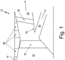
- FIG. 1 is a cross-sectional side view of fan section 12 of gas turbine engine 10.
- gas turbine engine 10 can be a high bypass turbofan engine that includes fan section 12, fan case 14, fan blades 16, core case 18, core passage 20, bypass duct 22, fan exit guide vanes (FEGV) 24, and acoustic liners 26.
- Fan blades 16 rotate within fan case 14 to pull air into gas turbine engine 10 and push the air past FEGV 24 and into bypass duct 22.
- a portion of the air flowing into gas turbine engine 10 is directed into core passage 20 for compression and combustion by gas turbine engine 10.
- Core case 18 surrounds an entrance to core passage 20 and separates bypass duct 22 from core passage 20.
- Acoustic liners 26 are connected to fan case 14 and are positioned upstream and downstream from fan blades 16. As fan blades 16 rotate and pull air into fan section 12 of gas turbine engine 10, fan blades 16 and the flowing air can generate noise. Acoustic liners 26 attenuate and dampen the noise generated by fan blades 16 and the air flowing through fan section 12. While FIG. 1 only shows acoustic liners 26 on fan case 14 of fan section 12, acoustic liners 26 can also be included on core case 18 and inside bypass duct 22, or in any location of gas turbine engine 10 that requires noise attenuation. As discussed in greater detail below with reference to FIGS. 2-5 , each of acoustic liners 26 includes an assembly of panels, with each panel including a perforated face sheet covering a honeycomb core. As the flow passages within gas turbine engine 10 are annular, the honeycomb core and the face sheet of each panel of acoustic liners 26 must also be curved.
- the honeycomb core of acoustic liners 26 can include cells that vary in size, depth, and geometry to target and attenuate different frequencies. Additive manufacturing the honeycomb core of acoustic liners 26 allows the honeycomb core to have a complex geometry that results in improved acoustic, weight, and drag characteristics over honeycomb cores in past acoustic liners. Additive manufacturing processes include the ability to produce highly complex parts quickly and efficiently, and to modify design specifications of the desired part, for example by modifying CAD specifications, without re-tooling casting or machining equipment used for traditional, subtractive manufacturing processes. Additive manufacturing allows complex design features to be incorporated into parts where those complex design features had proved infeasible using previous manufacturing techniques.
- Additive manufacturing generally involves printing a part layer by layer. Additive manufacturing a part with curvature does have several drawbacks. Additive manufacturing a part with curved surfaces often requires additional material and structures to support the curved surfaces. Additive manufacturing a curved surface can also impart a rough and stepped surface finish to the curved surface. Cell geometry can also be constrained when additive manufacturing a curved honeycomb core due to cell orientation in the curved honeycomb core. As discussed below with reference to FIGS. 2 and 3 , the problems involved with additive manufacturing a curved honeycomb core are avoided by forming the panels of acoustic liners 26 from a honeycomb core that is additive manufactured with a flat bottom.
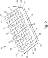
- FIG. 2 is a perspective view of acoustic liner panel 28 formed by additive manufacturing.
- acoustic liner panel 28 is generally rectangular with flat bottom FB, top side TS, first corner C1, second corner C2, third corner C3, fourth corner C4, fifth corner C5, sixth corner C6, seventh corner C7, and eighth corner C8.
- Acoustic liner panel 28 includes face sheet 30 and honeycomb core 32.
- Honeycomb core 32 includes a first plurality of walls 34, a second plurality of walls 36, and a plurality of cells 38.
- Each wall 34 of the first plurality of walls 34 extends in a lengthwise direction LD and includes top edge 42 and base edge 44.
- Each wall of the second plurality of walls 36 extends in a widthwise direction WD and includes top edge 46 and base edge 48.
- the first plurality of walls 34 and the second plurality of walls 36 both extend from face sheet 30 in a height-wise direction HD.
- First corner C1, second corner C2, third corner C3, and fourth corner C4 are the corners of flat bottom FB of acoustic liner panel 28.
- Fifth corner C5, sixth corner C6, seventh corner C7, and eighth corner C8 are the corners of top side TS of acoustic liner panel 28.
- Face sheet 30 is flat and forms flat bottom FB of acoustic liner panel 28.
- the first plurality of walls 34 includes lengthwise walls 34 that extend in the lengthwise direction LD.
- the second plurality of walls 36 includes widthwise walls 36 that extend in the widthwise direction WD and intersect the first plurality of walls 34 to form the plurality of cells 38.
- the first plurality of walls 34 and the second plurality of walls 36 are integral with face sheet 30 and both the first plurality of walls 34 and the second plurality of walls 36 extend from face sheet 30 in the height-wise direction HD to define a depth or height of each cell 38.
- the height-wise direction HD is the build direction of acoustic liner panel 28.
- Flat face sheet 30 is formed first, followed by honeycomb core 32. Since face sheet 30 is flat and honeycomb core 32 extends vertically up from face sheet 30, no support structure is needed to additive manufacture acoustic liner panel 28 and there are fewer constraints on the geometry of cells 38.
- Acoustic liner panel 28 can be additive manufactured from a polymer lighter than aluminum. In other examples, acoustic liner panel 28 can be additive manufactured from metal using a powder bed additive manufacturing process.
- Base edge 44 of each wall 34 of the first plurality of walls 34 is connected to face sheet 30 and extends straight in the lengthwise direction LD.
- Top edge 42 of each wall 34 of the first plurality of walls 34 is spaced from base edge 44 in the height-wise direction HD and extends in a wavy pattern in the lengthwise direction LD such that top edge 42 is corrugated.
- the wavy pattern of top edge 42 of each wall 34 of the first plurality of walls 34 has a wavelength extending in the lengthwise direction LD and an amplitude extending in the widthwise direction WD.
- the wavy pattern of top edge 42 can be sinusoidal, a spline, a series of tangent arcs, or even a series of angled straight lines.
- Each of walls 34 of the first plurality of walls 34 transitions from straight base edge 44 to wavy and corrugated top edge 42. While fifth corner C5 and seventh corner C7 of acoustic liner panel 28 can be spaced from each other in the lengthwise direction LD approximately the same distance that first corner C1 is spaced from third corner C3 in the lengthwise direction LD, top edge 42 of each wall 34 of the first plurality of walls 34 is greater in length than the length of base edge 44 if top edge 42 is stretched and straightened out.
- sixth corner C6 and eighth corner C8 of acoustic liner panel 28 can be spaced from each other in the lengthwise direction LD approximately the same distance that second corner C2 is spaced from fourth corner C4 in the lengthwise direction LD, top edge 42 of each wall 34 of the first plurality of walls 34 is greater in length than the length of base edge 44 if top edge 42 is stretched and straightened out.
- Base edge 48 of each wall 36 of the second plurality of walls 36 is connected to face sheet 30 and extends straight in the widthwise direction WD.
- Top edge 46 of each wall 36 of the second plurality of walls 36 is spaced from base edge 48 in the height-wise direction HD and extends in a wavy pattern in the widthwise direction WD such that top edge 46 is corrugated.
- the wavy pattern of top edge 46 of each wall 36 of the second plurality of walls 36 has a wavelength extending in the widthwise direction WD and an amplitude extending in the lengthwise direction LD.
- the wavy pattern of top edge 46 can be sinusoidal, a spline, a series of tangent arcs, or even a series of angled straight lines.
- Each of walls 36 of the second plurality of walls 36 transitions from straight base edge 48 to wavy and corrugated top edge 46. While fifth corner C5 and sixth corner C6 of acoustic liner panel 28 can be spaced from each other in the widthwise direction WD approximately the same distance that first corner C1 is spaced from second corner C2 in the widthwise direction WD, top edge 46 of each wall 36 of the second plurality of walls 36 is greater in length than the length of base edge 48 when top edge 46 is straightened out.
- top edge 46 of each wall 36 of the second plurality of walls 36 is greater in length than the length of base edge 48 when top edge 46 is straightened out.
- each of cells 38 comprises a rectangular profile (not visible) adjacent to flat bottom FB. Rectangular profile should be interpreted herein to also include profiles that are square and parallelogram in shape. As each cell 38 extends in the height-wise direction from flat base FB formed by face sheet 30 toward top side TS, each cell 3 8 transitions from the rectangular profile to a second profile. The second profile of each cell 38, as shown in FIG.
- the second profile shown in FIG. 2 can be produced by forming the wavy profile of top edge 42 of each wall 34 of the first plurality of walls 34 to be out of phase with the wavy profile of top edge 42 of each adj acent wall 34, and by forming the wavy profile of top edge 46 of each wall 36 of the second plurality of walls 36 to be out of phase with the wavy profile of top edge 46 of each adjacent wall 36.
- the first plurality of walls 34 and the second plurality of walls 36 can be additive manufactured to vary in height such that cells 38 can vary in depth or height in the widthwise direction WD and/or the lengthwise direction LD.
- a first wall of the first plurality of walls 34 can include a height different from a height of a second wall of the first plurality of walls 34.
- Top edge 42 of each wall 34 of the first plurality of walls 34 can have a wavy pattern that differs in amplitude from the rest of walls 34 of the first plurality of walls 34 such that each top edge 42 will have a different length when curved and stretched, allowing acoustic liner panel 28 to form curved and tapering acoustic liners 26.
- acoustic liner panel 28 with flat bottom FB is further processed to form curved acoustic liner panel 58 as described in detail below with reference to FIGS. 3A and 3B .
- FIG. 3A is a perspective view of acoustic liner panel 28 with flat bottom FB from FIG. 2 placed between first curved mold 50 with concave face 52 and second curved mold 54 with convex face 56 used to modify the acoustic liner panel 28 into curved acoustic liner panel 58, shown in FIG. 3B .
- acoustic liner panel 28 is placed between first curved mold 50 and second curved mold 54 with flat bottom FB of acoustic liner panel 28 facing convex face 56 and top side TS of acoustic liner panel 28 facing concave face 52.
- Acoustic liner panel 28, first curved mold 50, and second curved mold 54 are then heated together at the same time to a glass transition temperature of the polymer or metal forming acoustic liner panel 28.
- first curved mold 50 and second curved mold 54 are not heated, or are heated separate from acoustic liner panel 28, and acoustic liner panel 28 is heated to the glass transition temperature of the polymer or metal forming acoustic liner panel 28 before acoustic liner panel 28 is placed between first curved mold 50 and second curved mold 54.
- acoustic liner panel 28 After acoustic liner panel 28 is heated to the glass transition temperature, acoustic liner panel 28 is pressed between concave face 52 of first curved mold 50 and convex face 56 of second curved mold 54 to form curved acoustic liner panel 58. As acoustic liner panel 28 is pressed between first curved mold 50 and second curved mold 54 to form curved acoustic liner panel 58, face sheet 30 is curved into a concave shape and top edge 42 of each wall 34 of the first plurality of walls 34 is stretched to substantially eliminate the wavy pattern of top edge 42 such that top edge 42 is no longer corrugated.
- Top edge 46 of each wall 36 of the second plurality of walls 36 is also curved and stretched to substantially eliminate the wavy pattern of top edge 46 such that the top edge 46 is no longer corrugated.
- each cell 38 includes a rectangular profile through an entire depth or height of cell 38. While FIGS. 2-3B describe cells 38 as having a rectangular profile, in other examples, cells 38 can have a profile that is triangular or hexagonal.
- FIG. 4 is a cross-sectional view of multiple curved acoustic liner panels 58 from FIG. 3 assembled into an acoustic liner assembly forming an outer diameter flow surface.
- face sheet 30 of each acoustic liner panel 58 forms the outer diameter flow surface.
- Perforations 60 are formed in face sheet 30 before acoustic liner panel 28 is formed into curved acoustic liner panel 58 or after acoustic liner panel 28 is formed into curved acoustic liner panel 58.
- Perforations 60 allow fluid communication between the cells 38 of honeycomb core 32 and the air flow passage surrounded by curved acoustic liner panels 58.
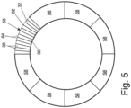
- FIG. 5 is a cross-sectional view of multiple curved acoustic liner panels 58 from FIG. 3 assembled into an acoustic liner assembly forming an outer diameter flow surface.
- second face sheet 62 is connected to top edge 42 of each wall 34 of the second plurality of walls 34 and to top edge 46 of each wall 36 of the second plurality of walls 36 after curved acoustic liner panel 58 is formed from acoustic liner panel 28.
- Second face sheet 62 is convex and forms the inner diameter flow surface.
- Perforations 64 are formed in second face sheet 62 and allow fluid communication between the cells 38 of honeycomb core 32 with the air flow passage surrounding curved acoustic liner panels 58 of FIG. 5 .
- acoustic liner panel 28 that can be additively manufactured as an initially flat structure and subsequently processed to form a curved acoustic liner in a gas turbine engine. Because acoustic liner panel 28 can be additively manufactured, acoustic liner panel can take advantage of the benefits of additive manufacturing (complex geometries, lighter-weight materials, reduce manufacturing steps) while also avoiding the disadvantages common to curved parts formed through additive manufacturing (increased material requirements, rough surface finish, and geometric constraints on honeycomb cells).
- FIGS. 2-3B describe cells 38 of honeycomb core 32 as having a rectangular profile, cells 38 can have a profile that is triangular or hexagonal.
- many modifications may be made to adapt a particular situation or material to the teachings of the invention without departing from the essential scope thereof. Therefore, it is intended that the invention not be limited to the particular embodiment(s) disclosed, but that the invention will include all embodiments falling within the scope of the appended claims.
Landscapes
- Engineering & Computer Science (AREA)
- Chemical & Material Sciences (AREA)
- Combustion & Propulsion (AREA)
- Manufacturing & Machinery (AREA)
- Physics & Mathematics (AREA)
- Mechanical Engineering (AREA)
- Materials Engineering (AREA)
- Multimedia (AREA)
- Acoustics & Sound (AREA)
- General Engineering & Computer Science (AREA)
- Thermal Sciences (AREA)
- Soundproofing, Sound Blocking, And Sound Damping (AREA)
- Laminated Bodies (AREA)
Abstract
A method for forming a curved acoustic liner panel includes additive manufacturing a honeycomb core (32) that includes a plurality of walls (34, 36). Each wall (34, 36) of the plurality of walls (34, 36) includes a straight base edge (44, 48) at a flat bottom (FB) of the honeycomb core (32) and a corrugated top edge (42, 46) opposite the straight base edge (44, 48). The honeycomb core (32) is heated and placed between a first curved mold and a second curved mold. The honeycomb core (32) is pressed between the first curved mold and the second curved mold to curve the honeycomb core (32) and stretch the corrugated top edge (42, 46) of each wall (34, 36) of the plurality of walls (34, 36) such that the top edge (42, 46) is no longer corrugated.
Description
- This disclosure relates to gas turbine engines in aircraft, and in particular, to an acoustic liner for reducing emitted noise propagating through a duct of the gas turbine engine.
- During operation an aircraft, a gas turbine engine of the aircraft generates noise that requires attenuation and control. Acoustic liners are provided within a flow duct of the gas turbine engine to attenuate the noise generated by the gas turbine engine. Current acoustic liners generally include a honeycomb core and a face sheet attached to the honeycomb core. The honeycomb core is generally made out of aluminum and the face sheet is typically made out of fiberglass or aluminum. The honeycomb core is cut to shape while in a flat sheet then expanded out to form a 3D volume. A drawback of this process is that honeycomb geometries must be fairly simple and straight forward to produce. Using additive manufacturing (AM) polymers allows for the creation of acoustic liners that have more complex geometry that may result in improved acoustic characteristics, lower weight, and less drag. However, most AM parts must be printed in discrete, flat layers, while acoustic liners in an engine are often curved around a center axis the engine. Printing AM acoustic liners in their curved shape leads to all sorts of drawbacks such as excess material used for support, rough surface finishes on the flow facing face sheet, and constraints placed on cell geometry due to cell orientation.
- An acoustic liner panel includes a honeycomb core with a plurality of lengthwise walls extending in a lengthwise direction. Each lengthwise wall of the plurality of lengthwise walls includes a base edge extending straight in the lengthwise direction and a top edge extending in a wavy pattern in the lengthwise direction, with the top edge being greater in length than the base edge. The honeycomb core also includes a plurality of widthwise walls extending in a widthwise direction. The plurality of widthwise walls intersects the plurality of lengthwise walls. Each widthwise wall of the plurality of widthwise walls includes a base edge extending straight in the widthwise direction and a top edge extending in a wavy pattern in the widthwise direction, with the top edge being greater in length than the base edge. A plurality of cells is formed by the plurality of lengthwise walls and the plurality of widthwise walls. Upon forming the honeycomb core into a curved acoustic liner panel, the top edges of both the lengthwise walls and the widthwise walls are stretched to substantially eliminate the wavy patterns in the top edges of both the lengthwise walls and the widthwise walls.
- In a further example of the foregoing, a flat face sheet connected to the base edge of each lengthwise wall of the plurality of lengthwise walls and connected to the base edge of each widthwise wall of the plurality of widthwise walls.
- In a further example of any of the foregoing, the wavy pattern of the top edge of each lengthwise wall of the plurality of lengthwise walls includes a wavelength extending in the lengthwise direction and an amplitude extending in the widthwise direction, and the top edge of each widthwise wall of the plurality of widthwise walls includes a wavelength extending in the widthwise direction and an amplitude extending in the widthwise direction.
- In a further example of any of the foregoing, the wavy pattern of the top edge of each lengthwise wall of the plurality of lengthwise walls is out of phase with the top edge of an adjacent lengthwise wall of the plurality of lengthwise walls.
- In a further example of any of the foregoing, the wavy pattern of the top edge of each widthwise wall of the plurality of widthwise walls is out of phase with the top edge of an adjacent widthwise wall of the plurality of widthwise walls.
- In a further example of any of the foregoing, a depth of the plurality of cells changes in the widthwise direction.
- In a further example of any of the foregoing, a first lengthwise wall of the plurality of lengthwise walls includes a height different from a height of a second lengthwise wall of the plurality of lengthwise walls.
- In a further example of any of the foregoing, a first lengthwise wall of the plurality of lengthwise walls includes a top edge with a wavy pattern that differs in amplitude from a wavy pattern of a top edge of a second lengthwise wall of the plurality of lengthwise walls.
- A method is disclosed for forming a curved acoustic liner panel by additive manufacturing the honeycomb core of any of the foregoing embodiments. The method includes placing the honeycomb core between a first curved mold and a second curved mold. The honeycomb core is heated and pressed between the first curved mold and the second curved mold to curve the honeycomb core and stretch the wavy pattern of the top edge of each lengthwise wall of the plurality of lengthwise walls. The honeycomb core is also pressed between the first curved mold and the second curved mold to stretch the wavy pattern of the top edge of each widthwise wall of the plurality of widthwise walls.
- In a further example of any of the foregoing, heating the first curved mold and the second curved mold at the same time as the heating of the honeycomb core.
- In a further example of any of the foregoing, heating the honeycomb core to a glass transition temperature of a material of the honeycomb core.
- In a further example of any of the foregoing, additive manufacturing a flat face sheet; and additive manufacturing the honeycomb core onto the flat face sheet.
- In a further example of any of the foregoing, connecting a second face sheet to the top edge of each lengthwise wall of the plurality of lengthwise walls and to the top edge of each widthwise wall of the plurality of widthwise walls.
- A honeycomb core, which the Applicant expressly reserves the right to claim independently, includes a first plurality of walls extending in a first direction and a second plurality of walls extending in a second direction. The second plurality of walls intersects the first plurality of walls to form a plurality of cells. Each wall of the first plurality of walls includes a base edge at a flat bottom of the honeycomb core that extends straight in the first direction and a top edge spaced from the base edge in a height-wise direction that extends in a wavy pattern in the first direction. Each wall of the second plurality of walls includes a base edge at the flat bottom of the honeycomb core that extends straight in the second direction and a top edge spaced from the base edge of the wall of the second plurality of walls that extends in a wavy pattern in the second direction.
- In a further example of any of the foregoing, a face sheet at the flat bottom of the honeycomb core and integral with the first plurality of walls and the second plurality of walls.
- In a further example of any of the foregoing, each cell of the plurality of cells includes a rectangular profile at the flat bottom of the honeycomb core.
- In a further example of any of the foregoing, each cell of the plurality of cells transitions in the height-wise direction from the rectangular profile to a second profile, wherein the second profile includes: a first concave side opposite a second concave side; and a first convex side opposite a second convex side.
- In a further example of any of the foregoing, the plurality of cells changes in height in the second direction.
- In a further example of any of the foregoing, a first wall of the first plurality of walls includes a top edge with a wavy pattern that differs in amplitude from a wavy pattern of a top edge of a second wall of the first plurality of walls.
- A method for forming a curved acoustic liner panel includes additive manufacturing a honeycomb core that includes a plurality of walls. Each wall of the plurality of walls includes a straight base edge at a flat bottom of the honeycomb core and a corrugated top edge opposite the straight base edge. The honeycomb core is placed between a first curved mold and a second curved mold. The honeycomb core, the first curved mold, and the second curved mold are heated. The honeycomb core is pressed between the first curved mold and the second curved mold to curve the honeycomb core and stretch the corrugated top edge of each wall of the plurality of walls such that the top edge is no longer corrugated.
- The present summary is provided only by way of example, and not limitation. Other aspects of the present disclosure will be appreciated in view of the entirety of the present disclosure, including the entire text, claims and accompanying figures.
-
-
FIG. 1 is a cross-sectional side view of a fan section of a gas turbine engine. -
FIG. 2 is a perspective view of a flat acoustic liner panel formed by additive manufacturing. -
FIG. 3A is a perspective view of the flat acoustic liner panel fromFIG. 2 placed in a curved mold. -
FIG. 3B is a perspective view of a curved acoustic liner panel formed from the flat acoustic liner panel and curved mold fromFIG. 2 . -
FIG. 4 is a cross-sectional view of an acoustic liner assembly forming an outer diameter flow surface. -
FIG. 5 is a cross-sectional view of an acoustic liner assembly forming an inner diameter flow surface. - While the above-identified figures set forth embodiments of the present invention, other embodiments are also contemplated, as noted in the discussion. In all cases, this disclosure presents the invention by way of representation and not limitation. It should be understood that numerous other modifications and embodiments can be devised by those skilled in the art, which fall within the scope and spirit of the principles of the invention. The figures may not be drawn to scale, and applications and embodiments of the present invention may include features, steps and/or components not specifically shown in the drawings.
- A method is disclosed for forming a curved acoustic liner panel using an initially flat and additively manufactured honeycomb core. The honeycomb core includes a plurality of walls forming a plurality of cells. Initially, the honeycomb core is additive manufactured such that the honeycomb core has a flat bottom and each wall of the plurality of walls has a base edge that is substantially straight and a top edge that is corrugated with a wavy pattern. The honeycomb core is placed between two curved molds and heated. The heated honeycomb core is pressed between the two curved molds to curve the honeycomb core. As the honeycomb core is pressed and curved between the two curved molds, the top edge of each wall of the plurality of walls is elongated and stretched such that the top edge is no longer corrugated or wavy. The honeycomb core and the method of forming the curved acoustic liner are described in detail below with reference to
FIGS. 1-5 . -
FIG. 1 is a cross-sectional side view offan section 12 ofgas turbine engine 10. As shown inFIG. 1 ,gas turbine engine 10 can be a high bypass turbofan engine that includesfan section 12,fan case 14,fan blades 16,core case 18,core passage 20,bypass duct 22, fan exit guide vanes (FEGV) 24, andacoustic liners 26.Fan blades 16 rotate withinfan case 14 to pull air intogas turbine engine 10 and push the air pastFEGV 24 and intobypass duct 22. A portion of the air flowing intogas turbine engine 10 is directed intocore passage 20 for compression and combustion bygas turbine engine 10.Core case 18 surrounds an entrance tocore passage 20 and separates bypassduct 22 fromcore passage 20. -
Acoustic liners 26 are connected to fancase 14 and are positioned upstream and downstream fromfan blades 16. Asfan blades 16 rotate and pull air intofan section 12 ofgas turbine engine 10,fan blades 16 and the flowing air can generate noise.Acoustic liners 26 attenuate and dampen the noise generated byfan blades 16 and the air flowing throughfan section 12. WhileFIG. 1 only showsacoustic liners 26 onfan case 14 offan section 12,acoustic liners 26 can also be included oncore case 18 and insidebypass duct 22, or in any location ofgas turbine engine 10 that requires noise attenuation. As discussed in greater detail below with reference toFIGS. 2-5 , each ofacoustic liners 26 includes an assembly of panels, with each panel including a perforated face sheet covering a honeycomb core. As the flow passages withingas turbine engine 10 are annular, the honeycomb core and the face sheet of each panel ofacoustic liners 26 must also be curved. - Noise and acoustics can vary by position inside
fan section 12. The honeycomb core ofacoustic liners 26 can include cells that vary in size, depth, and geometry to target and attenuate different frequencies. Additive manufacturing the honeycomb core ofacoustic liners 26 allows the honeycomb core to have a complex geometry that results in improved acoustic, weight, and drag characteristics over honeycomb cores in past acoustic liners. Additive manufacturing processes include the ability to produce highly complex parts quickly and efficiently, and to modify design specifications of the desired part, for example by modifying CAD specifications, without re-tooling casting or machining equipment used for traditional, subtractive manufacturing processes. Additive manufacturing allows complex design features to be incorporated into parts where those complex design features had proved infeasible using previous manufacturing techniques. - Additive manufacturing generally involves printing a part layer by layer. Additive manufacturing a part with curvature does have several drawbacks. Additive manufacturing a part with curved surfaces often requires additional material and structures to support the curved surfaces. Additive manufacturing a curved surface can also impart a rough and stepped surface finish to the curved surface. Cell geometry can also be constrained when additive manufacturing a curved honeycomb core due to cell orientation in the curved honeycomb core. As discussed below with reference to
FIGS. 2 and3 , the problems involved with additive manufacturing a curved honeycomb core are avoided by forming the panels ofacoustic liners 26 from a honeycomb core that is additive manufactured with a flat bottom. -
FIG. 2 is a perspective view ofacoustic liner panel 28 formed by additive manufacturing. As shown inFIG. 2 ,acoustic liner panel 28 is generally rectangular with flat bottom FB, top side TS, first corner C1, second corner C2, third corner C3, fourth corner C4, fifth corner C5, sixth corner C6, seventh corner C7, and eighth corner C8.Acoustic liner panel 28 includesface sheet 30 andhoneycomb core 32.Honeycomb core 32 includes a first plurality ofwalls 34, a second plurality ofwalls 36, and a plurality ofcells 38. Eachwall 34 of the first plurality ofwalls 34 extends in a lengthwise direction LD and includestop edge 42 andbase edge 44. Each wall of the second plurality ofwalls 36 extends in a widthwise direction WD and includestop edge 46 andbase edge 48. The first plurality ofwalls 34 and the second plurality ofwalls 36 both extend fromface sheet 30 in a height-wise direction HD. - First corner C1, second corner C2, third corner C3, and fourth corner C4 are the corners of flat bottom FB of
acoustic liner panel 28. Fifth corner C5, sixth corner C6, seventh corner C7, and eighth corner C8 are the corners of top side TS ofacoustic liner panel 28. Facesheet 30 is flat and forms flat bottom FB ofacoustic liner panel 28. The first plurality ofwalls 34 includeslengthwise walls 34 that extend in the lengthwise direction LD. The second plurality ofwalls 36 includes widthwisewalls 36 that extend in the widthwise direction WD and intersect the first plurality ofwalls 34 to form the plurality ofcells 38. The first plurality ofwalls 34 and the second plurality ofwalls 36 are integral withface sheet 30 and both the first plurality ofwalls 34 and the second plurality ofwalls 36 extend fromface sheet 30 in the height-wise direction HD to define a depth or height of eachcell 38. Whenacoustic liner panel 28 is additive manufactured, the height-wise direction HD is the build direction ofacoustic liner panel 28.Flat face sheet 30 is formed first, followed byhoneycomb core 32. Sinceface sheet 30 is flat andhoneycomb core 32 extends vertically up fromface sheet 30, no support structure is needed to additive manufactureacoustic liner panel 28 and there are fewer constraints on the geometry ofcells 38.Acoustic liner panel 28 can be additive manufactured from a polymer lighter than aluminum. In other examples,acoustic liner panel 28 can be additive manufactured from metal using a powder bed additive manufacturing process. -
Base edge 44 of eachwall 34 of the first plurality ofwalls 34 is connected to facesheet 30 and extends straight in the lengthwise direction LD.Top edge 42 of eachwall 34 of the first plurality ofwalls 34 is spaced frombase edge 44 in the height-wise direction HD and extends in a wavy pattern in the lengthwise direction LD such thattop edge 42 is corrugated. The wavy pattern oftop edge 42 of eachwall 34 of the first plurality ofwalls 34 has a wavelength extending in the lengthwise direction LD and an amplitude extending in the widthwise direction WD. The wavy pattern oftop edge 42 can be sinusoidal, a spline, a series of tangent arcs, or even a series of angled straight lines. Each ofwalls 34 of the first plurality ofwalls 34 transitions fromstraight base edge 44 to wavy and corrugatedtop edge 42. While fifth corner C5 and seventh corner C7 ofacoustic liner panel 28 can be spaced from each other in the lengthwise direction LD approximately the same distance that first corner C1 is spaced from third corner C3 in the lengthwise direction LD,top edge 42 of eachwall 34 of the first plurality ofwalls 34 is greater in length than the length ofbase edge 44 iftop edge 42 is stretched and straightened out. In similar fashion, while sixth corner C6 and eighth corner C8 ofacoustic liner panel 28 can be spaced from each other in the lengthwise direction LD approximately the same distance that second corner C2 is spaced from fourth corner C4 in the lengthwise direction LD,top edge 42 of eachwall 34 of the first plurality ofwalls 34 is greater in length than the length ofbase edge 44 iftop edge 42 is stretched and straightened out. -
Base edge 48 of eachwall 36 of the second plurality ofwalls 36 is connected to facesheet 30 and extends straight in the widthwise direction WD.Top edge 46 of eachwall 36 of the second plurality ofwalls 36 is spaced frombase edge 48 in the height-wise direction HD and extends in a wavy pattern in the widthwise direction WD such thattop edge 46 is corrugated. The wavy pattern oftop edge 46 of eachwall 36 of the second plurality ofwalls 36 has a wavelength extending in the widthwise direction WD and an amplitude extending in the lengthwise direction LD. The wavy pattern oftop edge 46 can be sinusoidal, a spline, a series of tangent arcs, or even a series of angled straight lines. Each ofwalls 36 of the second plurality ofwalls 36 transitions fromstraight base edge 48 to wavy and corrugatedtop edge 46. While fifth corner C5 and sixth corner C6 ofacoustic liner panel 28 can be spaced from each other in the widthwise direction WD approximately the same distance that first corner C1 is spaced from second corner C2 in the widthwise direction WD,top edge 46 of eachwall 36 of the second plurality ofwalls 36 is greater in length than the length ofbase edge 48 whentop edge 46 is straightened out. In similar fashion, while seventh corner C7 and eighth corner C8 ofacoustic liner panel 28 can be spaced from each other in the widthwise direction WD approximately the same distance that third corner C3 is spaced from fourth corner C4 in the widthwise wise direction WD,top edge 46 of eachwall 36 of the second plurality ofwalls 36 is greater in length than the length ofbase edge 48 whentop edge 46 is straightened out. - In the example of
FIG. 2 , sincebase edge 44 of eachwall 34 of the first plurality ofwalls 34 extends straight in the lengthwise direction LD, and sincebase edge 48 of eachwall 36 of the second plurality ofwalls 36 extends straight in the widthwise direction WD, each ofcells 38 comprises a rectangular profile (not visible) adjacent to flat bottom FB. Rectangular profile should be interpreted herein to also include profiles that are square and parallelogram in shape. As eachcell 38 extends in the height-wise direction from flat base FB formed byface sheet 30 toward top side TS, each cell 3 8 transitions from the rectangular profile to a second profile. The second profile of eachcell 38, as shown inFIG. 2 , includes a first concave side opposite a second concave side, and a first convex side opposite a second convex side. The second profile shown inFIG. 2 can be produced by forming the wavy profile oftop edge 42 of eachwall 34 of the first plurality ofwalls 34 to be out of phase with the wavy profile oftop edge 42 of each adj acentwall 34, and by forming the wavy profile oftop edge 46 of eachwall 36 of the second plurality ofwalls 36 to be out of phase with the wavy profile oftop edge 46 of eachadjacent wall 36. - The first plurality of
walls 34 and the second plurality ofwalls 36 can be additive manufactured to vary in height such thatcells 38 can vary in depth or height in the widthwise direction WD and/or the lengthwise direction LD. For example, a first wall of the first plurality ofwalls 34 can include a height different from a height of a second wall of the first plurality ofwalls 34.Top edge 42 of eachwall 34 of the first plurality ofwalls 34 can have a wavy pattern that differs in amplitude from the rest ofwalls 34 of the first plurality ofwalls 34 such that eachtop edge 42 will have a different length when curved and stretched, allowingacoustic liner panel 28 to form curved and taperingacoustic liners 26. Onceacoustic liner panel 28 is additively formed,acoustic liner panel 28 with flat bottom FB is further processed to form curvedacoustic liner panel 58 as described in detail below with reference toFIGS. 3A and 3B . -
FIGS. 3A and 3B will be discussed concurrently.FIG. 3A is a perspective view ofacoustic liner panel 28 with flat bottom FB fromFIG. 2 placed between firstcurved mold 50 withconcave face 52 and secondcurved mold 54 withconvex face 56 used to modify theacoustic liner panel 28 into curvedacoustic liner panel 58, shown inFIG. 3B . Afteracoustic liner panel 28 fromFIG. 2 is formed,acoustic liner panel 28 is placed between firstcurved mold 50 and secondcurved mold 54 with flat bottom FB ofacoustic liner panel 28 facingconvex face 56 and top side TS ofacoustic liner panel 28 facingconcave face 52.Acoustic liner panel 28, firstcurved mold 50, and secondcurved mold 54 are then heated together at the same time to a glass transition temperature of the polymer or metal formingacoustic liner panel 28. In other examples, firstcurved mold 50 and secondcurved mold 54 are not heated, or are heated separate fromacoustic liner panel 28, andacoustic liner panel 28 is heated to the glass transition temperature of the polymer or metal formingacoustic liner panel 28 beforeacoustic liner panel 28 is placed between firstcurved mold 50 and secondcurved mold 54. - After
acoustic liner panel 28 is heated to the glass transition temperature,acoustic liner panel 28 is pressed betweenconcave face 52 of firstcurved mold 50 andconvex face 56 of secondcurved mold 54 to form curvedacoustic liner panel 58. Asacoustic liner panel 28 is pressed between firstcurved mold 50 and secondcurved mold 54 to form curvedacoustic liner panel 58,face sheet 30 is curved into a concave shape andtop edge 42 of eachwall 34 of the first plurality ofwalls 34 is stretched to substantially eliminate the wavy pattern oftop edge 42 such thattop edge 42 is no longer corrugated.Top edge 46 of eachwall 36 of the second plurality ofwalls 36 is also curved and stretched to substantially eliminate the wavy pattern oftop edge 46 such that thetop edge 46 is no longer corrugated. Onceacoustic liner panel 28 has been pressed and shaped into curvedacoustic liner panel 58 by firstcurved mold 50 and secondcurved mold 54, eachcell 38 includes a rectangular profile through an entire depth or height ofcell 38. WhileFIGS. 2-3B describecells 38 as having a rectangular profile, in other examples,cells 38 can have a profile that is triangular or hexagonal. -
FIG. 4 is a cross-sectional view of multiple curvedacoustic liner panels 58 fromFIG. 3 assembled into an acoustic liner assembly forming an outer diameter flow surface. As shown inFIG. 4 ,face sheet 30 of eachacoustic liner panel 58 forms the outer diameter flow surface.Perforations 60 are formed inface sheet 30 beforeacoustic liner panel 28 is formed into curvedacoustic liner panel 58 or afteracoustic liner panel 28 is formed into curvedacoustic liner panel 58.Perforations 60 allow fluid communication between thecells 38 ofhoneycomb core 32 and the air flow passage surrounded by curvedacoustic liner panels 58. -
FIG. 5 is a cross-sectional view of multiple curvedacoustic liner panels 58 fromFIG. 3 assembled into an acoustic liner assembly forming an outer diameter flow surface. In the example ofFIG. 5 ,second face sheet 62 is connected totop edge 42 of eachwall 34 of the second plurality ofwalls 34 and totop edge 46 of eachwall 36 of the second plurality ofwalls 36 after curvedacoustic liner panel 58 is formed fromacoustic liner panel 28.Second face sheet 62 is convex and forms the inner diameter flow surface.Perforations 64 are formed insecond face sheet 62 and allow fluid communication between thecells 38 ofhoneycomb core 32 with the air flow passage surrounding curvedacoustic liner panels 58 ofFIG. 5 . - As discussed above with reference to the figures, the disclosed apparatus and method provides
acoustic liner panel 28 that can be additively manufactured as an initially flat structure and subsequently processed to form a curved acoustic liner in a gas turbine engine. Becauseacoustic liner panel 28 can be additively manufactured, acoustic liner panel can take advantage of the benefits of additive manufacturing (complex geometries, lighter-weight materials, reduce manufacturing steps) while also avoiding the disadvantages common to curved parts formed through additive manufacturing (increased material requirements, rough surface finish, and geometric constraints on honeycomb cells). - While the invention has been described with reference to an exemplary embodiment(s), it will be understood by those skilled in the art that various changes may be made and equivalents may be substituted for elements thereof without departing from the scope of the invention. For example, while
FIGS. 2-3B describecells 38 ofhoneycomb core 32 as having a rectangular profile,cells 38 can have a profile that is triangular or hexagonal. In addition, many modifications may be made to adapt a particular situation or material to the teachings of the invention without departing from the essential scope thereof. Therefore, it is intended that the invention not be limited to the particular embodiment(s) disclosed, but that the invention will include all embodiments falling within the scope of the appended claims.
Claims (14)
- An acoustic liner panel (28; 58) comprising:
a honeycomb core (32) comprising:a plurality of lengthwise walls (34) extending in a lengthwise direction (LD), wherein each lengthwise wall (34) of the plurality of lengthwise walls (34) comprises:a base edge (44) extending straight in the lengthwise direction (LD); anda top edge (42) extending in a wavy pattern in the lengthwise direction (LD), wherein the top edge (42) is greater in length than the base edge (44);a plurality of widthwise walls (36) extending in a widthwise direction (WD), wherein the plurality of widthwise walls (36) intersects the plurality of lengthwise walls (34), and wherein each widthwise wall (36) of the plurality of widthwise walls (36) comprises:a base edge (48) extending straight in the widthwise direction (WD); anda top edge (46) extending in a wavy pattern in the widthwise direction (WD), wherein the top edge (46) is greater in length than the base edge (48); anda plurality of cells (38) formed by the plurality of lengthwise walls (34) and the plurality of widthwise walls (36),
wherein upon forming said honeycomb core (32) into a curved acoustic liner panel (58), the top edges (42, 46) of both the lengthwise walls (34) and the widthwise walls (36) are stretched to substantially eliminate the wavy patterns in the top edges (42, 46) of both the lengthwise walls (34) and the widthwise walls (36). - The acoustic liner panel of claim 1, further comprising:
a flat face sheet (30) connected to the base edge (44) of each lengthwise wall (34) of the plurality of lengthwise walls (34) and connected to the base edge (48) of each widthwise wall (36) of the plurality of widthwise walls (36). - The acoustic liner panel of claim 1 or 2, wherein:the wavy pattern of the top edge (42) of each lengthwise wall (34) of the plurality of lengthwise walls (34) comprises a wavelength extending in the lengthwise direction (LD) and an amplitude extending in the widthwise direction (WD), andthe top edge (46) of each widthwise wall (36) of the plurality of widthwise walls (36) comprises a wavelength extending in the widthwise direction (WD) and an amplitude extending in the lengthwise direction (LD).
- The acoustic liner panel of any preceding claim, wherein the wavy pattern of the top edge (42) of each lengthwise wall (34) of the plurality of lengthwise walls (34) is out of phase with the top edge (42) of an adjacent lengthwise wall (34) of the plurality of lengthwise walls (34).
- The acoustic liner panel of any preceding claim, wherein the wavy pattern of the top edge (46) of each widthwise wall (36) of the plurality of widthwise walls (36) is out of phase with the top edge (46) of an adjacent widthwise wall (36) of the plurality of widthwise walls (36).
- The acoustic liner panel of any preceding claim, wherein a depth of the plurality of cells (38) changes in the widthwise direction (WD).
- The acoustic liner panel of any preceding claim, wherein a first lengthwise wall (34) of the plurality of lengthwise walls (34) comprises a height different from a height of a second lengthwise wall (34) of the plurality of lengthwise walls (34).
- The acoustic liner panel of any preceding claim, wherein a first lengthwise wall (34) of the plurality of lengthwise walls (34) comprises a top edge (42) with a wavy pattern that differs in amplitude from a wavy pattern of a top edge (42) of a second lengthwise wall (34) of the plurality of lengthwise walls (34).
- A method for forming a curved acoustic liner panel (58) comprises:additive manufacturing the honeycomb core (32) of claim 1;placing the honeycomb core (32) between a first curved mold (50) and a second curved mold (54);heating the honeycomb core (32);pressing the honeycomb core (32) between the first curved mold (50) and the second curved mold (54) to curve the honeycomb core (32) and stretch the wavy pattern of the top edge (42) of each lengthwise wall (34) of the plurality of lengthwise walls (34);pressing the honeycomb core (32) between the first curved mold (50) and the second curved mold (54) to stretch the wavy pattern of the top edge (46) of each widthwise wall (36) of the plurality of widthwise walls (36).
- The method of claim 9, further comprising:
heating the first curved mold (50) and the second curved mold (54) at the same time as the heating of the honeycomb core (32). - The method of claim 9 or 10, further comprising:
heating the honeycomb core (32) to a glass transition temperature of a material of the honeycomb core (32). - The method of any of claims 9 to 11, further comprising:additive manufacturing a flat face sheet (30); andadditive manufacturing the honeycomb core (32) onto the flat face sheet (30).
- The method of any of claims 9 to 12, further comprising:
connecting a second face sheet (62) to the top edge (42) of each lengthwise wall (34) of the plurality of lengthwise walls (34) and to the top edge (46) of each widthwise wall (36) of the plurality of widthwise walls (36). - A method for forming a curved acoustic liner panel (58) comprises:additive manufacturing a honeycomb core (32), wherein the honeycomb core (32) comprises a plurality of walls (34, 36), wherein each wall (34, 36) of the plurality of walls (34, 36) comprises a straight base edge (44, 48) at a flat bottom (FB) of the honeycomb core (32) and a corrugated top edge (42, 46) opposite the straight base edge (44, 48);placing the honeycomb core (32) between a first curved mold (50) and a second curved mold (54);heating the honeycomb core (32), the first curved mold (50), and the second curved mold (54); andpressing the honeycomb core (32) between the first curved mold (50) and the second curved mold (54) to curve the honeycomb core (32) and stretch the corrugated top edge (42, 46) of each wall (34, 36) of the plurality of walls (34, 36) such that the top edge (42, 46) is no longer corrugated.
Applications Claiming Priority (1)
| Application Number | Priority Date | Filing Date | Title |
|---|---|---|---|
| US18/328,024 US12546253B2 (en) | 2023-06-02 | 2023-06-02 | Method for designing formable additively manufactured acoustic liners |
Publications (1)
| Publication Number | Publication Date |
|---|---|
| EP4471759A1 true EP4471759A1 (en) | 2024-12-04 |
Family
ID=91276828
Family Applications (1)
| Application Number | Title | Priority Date | Filing Date |
|---|---|---|---|
| EP24178095.6A Pending EP4471759A1 (en) | 2023-06-02 | 2024-05-24 | Method for designing formable additively manufactured acoustic liners |
Country Status (2)
| Country | Link |
|---|---|
| US (1) | US12546253B2 (en) |
| EP (1) | EP4471759A1 (en) |
Citations (4)
| Publication number | Priority date | Publication date | Assignee | Title |
|---|---|---|---|---|
| US4323614A (en) * | 1976-03-31 | 1982-04-06 | Corning Glass Works | Ceramic honeycomb structure |
| EP1125704A1 (en) * | 1999-08-30 | 2001-08-22 | Ngk Insulators, Ltd. | Corrugated wall honeycomb structure and production method thereof |
| US20080145602A1 (en) * | 2006-12-15 | 2008-06-19 | Gary Lee Hendren | Processes for making shaped honeycomb and honeycombs made thereby |
| US20210380220A1 (en) * | 2019-02-26 | 2021-12-09 | Safran Nacelles | Expandable cellular system for a sandwich panel |
Family Cites Families (4)
| Publication number | Priority date | Publication date | Assignee | Title |
|---|---|---|---|---|
| US6871725B2 (en) | 2003-02-21 | 2005-03-29 | Jeffrey Don Johnson | Honeycomb core acoustic unit with metallurgically secured deformable septum, and method of manufacture |
| FR3016315B1 (en) * | 2014-01-15 | 2016-02-05 | Chermant Alexis | METHOD FOR PRODUCING A SOUTH OF STRUCTURAL MATERIAL FOR POLYMER SANDWICH, SOUL AND MATERIAL |
| US11434819B2 (en) | 2019-03-29 | 2022-09-06 | General Electric Company | Acoustic liners with enhanced acoustic absorption and reduced drag characteristics |
| CN111457237B (en) | 2020-05-26 | 2023-04-07 | 北京安达泰克科技有限公司 | Flexible honeycomb structure and manufacturing method thereof |
-
2023
- 2023-06-02 US US18/328,024 patent/US12546253B2/en active Active
-
2024
- 2024-05-24 EP EP24178095.6A patent/EP4471759A1/en active Pending
Patent Citations (4)
| Publication number | Priority date | Publication date | Assignee | Title |
|---|---|---|---|---|
| US4323614A (en) * | 1976-03-31 | 1982-04-06 | Corning Glass Works | Ceramic honeycomb structure |
| EP1125704A1 (en) * | 1999-08-30 | 2001-08-22 | Ngk Insulators, Ltd. | Corrugated wall honeycomb structure and production method thereof |
| US20080145602A1 (en) * | 2006-12-15 | 2008-06-19 | Gary Lee Hendren | Processes for making shaped honeycomb and honeycombs made thereby |
| US20210380220A1 (en) * | 2019-02-26 | 2021-12-09 | Safran Nacelles | Expandable cellular system for a sandwich panel |
Also Published As
| Publication number | Publication date |
|---|---|
| US20240401528A1 (en) | 2024-12-05 |
| US12546253B2 (en) | 2026-02-10 |
Similar Documents
| Publication | Publication Date | Title |
|---|---|---|
| EP3259125B1 (en) | Acoustic liners and method of shaping an inlet of an acoustic liner | |
| EP3450738A1 (en) | Acoustic liner having internal structure | |
| US11915679B2 (en) | Continuous degree of freedom acoustic cores | |
| US11098601B2 (en) | Diffuser-deswirler for a gas turbine engine | |
| EP3268550B1 (en) | Acoustic liners for use in a turbine engine | |
| EP3708500A1 (en) | Acoustic paneling | |
| EP2947274A1 (en) | Turbulating cooling structures | |
| EP3613995B1 (en) | Method for designing blade of axial-flow fluid machine and blade | |
| US20180016981A1 (en) | Acoustic paneling | |
| US10626886B2 (en) | Sound attenuation apparatus and methods | |
| CN111511540B (en) | Coating with property gradient for turbine engine inner wall | |
| EP4471759A1 (en) | Method for designing formable additively manufactured acoustic liners | |
| CN114341465A (en) | Integrated nozzle and diaphragm with optimized internal vane thickness | |
| CN101636575A (en) | A kind of implementation methods of noise reduction liner and the liner that obtains with the method | |
| US20230286640A1 (en) | Acoustic absorber for a gas turbine engine | |
| RU2455510C2 (en) | Method to perform coating for acoustic treatment, including cellular structure of complex shape, and coating for acoustic treatment obtained thereof | |
| US20230112668A1 (en) | Dissimilarly shaped aircraft nozzles with tandem mixing devices, and associated systems and methods | |
| Wallin et al. | Intermediate turbine duct design and optimization | |
| NL2018888B1 (en) | Acoustic paneling | |
| Chong et al. | Design and characterisation of a quiet, low turbulence open jet blow down wind tunnel in ISVR | |
| Deshpande et al. | Efficiency Improvements in an Industrial Steam Turbine Stage: Part 1 |
Legal Events
| Date | Code | Title | Description |
|---|---|---|---|
| PUAI | Public reference made under article 153(3) epc to a published international application that has entered the european phase |
Free format text: ORIGINAL CODE: 0009012 |
|
| STAA | Information on the status of an ep patent application or granted ep patent |
Free format text: STATUS: THE APPLICATION HAS BEEN PUBLISHED |
|
| AK | Designated contracting states |
Kind code of ref document: A1 Designated state(s): AL AT BE BG CH CY CZ DE DK EE ES FI FR GB GR HR HU IE IS IT LI LT LU LV MC ME MK MT NL NO PL PT RO RS SE SI SK SM TR |
|
| STAA | Information on the status of an ep patent application or granted ep patent |
Free format text: STATUS: REQUEST FOR EXAMINATION WAS MADE |
|
| 17P | Request for examination filed |
Effective date: 20250530 |