EP4471724A1 - Method and system for generic garment simulation - Google Patents
Method and system for generic garment simulation Download PDFInfo
- Publication number
- EP4471724A1 EP4471724A1 EP24177195.5A EP24177195A EP4471724A1 EP 4471724 A1 EP4471724 A1 EP 4471724A1 EP 24177195 A EP24177195 A EP 24177195A EP 4471724 A1 EP4471724 A1 EP 4471724A1
- Authority
- EP
- European Patent Office
- Prior art keywords
- garment
- vertex
- template
- displacement
- handle
- Prior art date
- Legal status (The legal status is an assumption and is not a legal conclusion. Google has not performed a legal analysis and makes no representation as to the accuracy of the status listed.)
- Pending
Links
Images








Classifications
-
- G—PHYSICS
- G06—COMPUTING OR CALCULATING; COUNTING
- G06T—IMAGE DATA PROCESSING OR GENERATION, IN GENERAL
- G06T13/00—Animation
- G06T13/20—Three-dimensional [3D] animation
- G06T13/40—Three-dimensional [3D] animation of characters, e.g. humans, animals or virtual beings
-
- G—PHYSICS
- G06—COMPUTING OR CALCULATING; COUNTING
- G06F—ELECTRIC DIGITAL DATA PROCESSING
- G06F30/00—Computer-aided design [CAD]
- G06F30/10—Geometric CAD
- G06F30/17—Mechanical parametric or variational design
-
- G—PHYSICS
- G06—COMPUTING OR CALCULATING; COUNTING
- G06T—IMAGE DATA PROCESSING OR GENERATION, IN GENERAL
- G06T19/00—Manipulating three-dimensional [3D] models or images for computer graphics
- G06T19/20—Editing of three-dimensional [3D] images, e.g. changing shapes or colours, aligning objects or positioning parts
-
- G—PHYSICS
- G06—COMPUTING OR CALCULATING; COUNTING
- G06T—IMAGE DATA PROCESSING OR GENERATION, IN GENERAL
- G06T2210/00—Indexing scheme for image generation or computer graphics
- G06T2210/16—Cloth
-
- G—PHYSICS
- G06—COMPUTING OR CALCULATING; COUNTING
- G06T—IMAGE DATA PROCESSING OR GENERATION, IN GENERAL
- G06T2219/00—Indexing scheme for manipulating 3D models or images for computer graphics
- G06T2219/20—Indexing scheme for editing of 3D models
- G06T2219/2021—Shape modification
Definitions
- the disclosure herein generally relates to garment simulation, and, more particularly, to a method and system for generic garment simulation.
- a processor implemented method includes obtaining, via one or more hardware processors, a garment template, an initial body pose, and a target body pose, as input data. Further, the garment template is aligned via the one or more hardware processors, on the target body pose, by estimating a body motion-aware as-rigid-as-possible (ARAP) garment deformation from the obtained input data.
- ARAP body motion-aware as-rigid-as-possible
- a per-vertex displacement of the garment template is determined, via the one or more hardware processors, using a Physics Enforcing Network (PEN) based on the obtained input data and the estimated body motion-aware ARAP garment deformation.
- the PEN is trained using a restrain energy loss, wherein computing the restrain energy loss comprises: estimating absolute difference between edge length in the garment template and an associated edge length in a deformed garment template obtained using the motion-aware ARAP, for all of a plurality of edges; and computing the restrain energy loss based on the estimated absolute difference.
- a final deformed garment template is generated via the one or more hardware processors, for the target pose, by adding the determined per-vertex displacement of the garment template to the estimated body motion-aware ARAP garment deformation.
- estimating a body motion-aware as-rigid-as-possible (ARAP) garment deformation includes obtaining an index set of handle vertices of the garment template and associated displacement locations. Further, a displacement vector is computed for each handle vertex in the index set of handle vertices, with respect to position of the handle vertex indicated by the associated displacement location.
- ARAP as-rigid-as-possible
- the following steps are performed for a pre-defined number of iterations: moving the handle vertices towards a final location in direction of the displacement vector, in a plurality of iterations; solving each non-handle vertex using ARAP; and solving collision of one or more of the handle vertices with body in the target body pose, comprising: identifying index of closest body vertex for each deformed non-handle vertex, and associated unit normal vector; identifying one or more collided vectors as projection of body to a garment vector onto the unit normal vector; and resolving identified collision by moving the one or more collided vectors towards a closest body vertex normal with a defined magnitude.
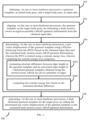
- determining the per-vertex displacement of the garment template using the Physics Enforcing Network includes the following steps. Initially, one or more latent features of the garment template and the initial body pose are obtained from a geometry encoder. Further, the one or more latent features are concatenated with a plurality of parameters to obtain concatenated feature vector. Further, a node feature vector is obtained by processing the concatenated feature vector using a node encoder. Further, a relative position of edge end-vertices in the garment template and estimated garment deformation are determined. Further, the determined relative position of edge end-vertices are encoded into an edge feature vector using an edge encoder. Further, an encoded garment graph is constructed using the node feature vector and edge feature vector.
- PEN Physics Enforcing Network
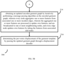
- an updated encoded garment graph is obtained by iteratively performing a message passing algorithm on the encoded garment graph, wherein every node aggregates one or more features from associated one or more incident edges, wherein the aggregated one or more features are processed to update own features, and are broadcasted to one or more neighboring nodes, and every edge node updates own features by taking the features from associated end nodes. Further, the per-vertex displacement of the garment template is determined by passing the updated garment graph through a displacement decoder.
- the plurality of parameters include a) a relative position of garment template vertex with respect to closest canonical pose body vertex, b) relative position of ARAP deformed garment template vertex with respect to closest target pose body vertex, c) a normal vector of the body vertex, d) a pin vertex indicator, e) a body motion vector, and f) a mass of the garment template vertex proportional to the area of associated faces.
- the initial body pose is a 3D human body in the canonical body pose.
- a system in yet another embodiment, includes one or more hardware processors, a communication interface, and a memory storing a plurality of instructions.
- the plurality of instructions when executed, cause the one or more hardware processors to obtain a garment template, an initial body pose, and a target body pose, as input data. Further, the garment template is aligned via the one or more hardware processors, on the target body pose, by estimating a body motion-aware as-rigid-as-possible (ARAP) garment deformation from the obtained input data.
- ARAP body motion-aware as-rigid-as-possible
- a per-vertex displacement of the garment template is determined, via the one or more hardware processors, using a Physics Enforcing Network (PEN) based on the obtained input data and the estimated body motion-aware ARAP garment deformation.
- the PEN is trained using a restrain energy loss, wherein computing the restrain energy loss comprises: estimating absolute difference between edge length in the garment template and an associated edge length in a deformed garment template obtained using the motion-aware ARAP, for all of a plurality of edges; and computing the restrain energy loss based on the estimated absolute difference.
- a final deformed garment template is generated via the one or more hardware processors, for the target pose, by adding the determined per-vertex displacement of the garment template to the estimated body motion-aware ARAP garment deformation.
- the one or more hardware processors are configured to estimate a body motion-aware as-rigid-as-possible (ARAP) garment deformation by obtaining an index set of handle vertices of the garment template and associated displacement locations. Further, a displacement vector is computed for each handle vertex in the index set of handle vertices, with respect to position of the handle vertex indicated by the associated displacement location.
- ARAP body motion-aware as-rigid-as-possible
- the following steps are performed for a pre-defined number of iterations: moving the handle vertices towards a final location in direction of the displacement vector, in a plurality of iterations; solving each non-handle vertex using ARAP; and solving collision of one or more of the handle vertices with body in the target body pose, comprising: identifying index of closest body vertex for each deformed non-handle vertex, and associated unit normal vector; identifying one or more collided vectors as projection of body to a garment vector onto the unit normal vector; and resolving identified collision by moving the one or more collided vectors towards a closest body vertex normal with a defined magnitude.
- the one or more hardware processors are configured to determine the per-vertex displacement of the garment template using the Physics Enforcing Network (PEN), using the following steps. Initially, one or more latent features of the garment template and the initial body pose are obtained from a geometry encoder. Further, the one or more latent features are concatenated with a plurality of parameters to obtain concatenated feature vector. Further, a node feature vector is obtained by processing the concatenated feature vector using a node encoder. Further, a relative position of edge end-vertices in the garment template and estimated garment deformation are determined. Further, the determined relative position of edge end-vertices are encoded into an edge feature vector using an edge encoder.
- PEN Physics Enforcing Network
- an encoded garment graph is constructed using the node feature vector and edge feature vector. Further, an updated encoded garment graph is obtained by iteratively performing a message passing algorithm on the encoded garment graph, wherein every node aggregates one or more features from associated one or more incident edges, wherein the aggregated one or more features are processed to update own features, and are broadcasted to one or more neighboring nodes, and every edge node updates own features by taking the features from associated end nodes. Further, the per-vertex displacement of the garment template is determined by passing the updated garment graph through a displacement decoder.
- the plurality of parameters include a) a relative position of garment template vertex with respect to closest canonical pose body vertex, b) relative position of ARAP deformed garment template vertex with respect to closest target pose body vertex, c) a normal vector of the body vertex, d) a pin vertex indicator, e) a body motion vector, and f) a mass of the garment template vertex proportional to the area of associated faces.
- the initial body pose is a 3D human body in the canonical body pose.
- a non-transitory computer readable medium includes a plurality of instructions, which when executed, cause the one or more hardware processors to obtain a garment template, an initial body pose, and a target body pose, as input data. Further, the garment template is aligned via the one or more hardware processors, on the target body pose, by estimating a body motion-aware as-rigid-as-possible (ARAP) garment deformation from the obtained input data. Further, a per-vertex displacement of the garment template is determined, via the one or more hardware processors, using a Physics Enforcing Network (PEN) based on the obtained input data and the estimated body motion-aware ARAP garment deformation.
- PEN Physics Enforcing Network
- the PEN is trained using a restrain energy loss, wherein computing the restrain energy loss comprises: estimating absolute difference between edge length in the garment template and an associated edge length in a deformed garment template obtained using the motion-aware ARAP, for all of a plurality of edges; and computing the restrain energy loss based on the estimated absolute difference.
- a final deformed garment template is generated via the one or more hardware processors, for the target pose, by adding the determined per-vertex displacement of the garment template to the estimated body motion-aware ARAP garment deformation.
- the non-transitory computer readable medium causes the one or more hardware processors to estimate a body motion-aware as-rigid-as-possible (ARAP) garment deformation by obtaining an index set of handle vertices of the garment template and associated displacement locations. Further, a displacement vector is computed for each handle vertex in the index set of handle vertices, with respect to position of the handle vertex indicated by the associated displacement location.
- ARAP body motion-aware as-rigid-as-possible
- the following steps are performed for a pre-defined number of iterations: moving the handle vertices towards a final location in direction of the displacement vector, in a plurality of iterations; solving each non-handle vertex using ARAP; and solving collision of one or more of the handle vertices with body in the target body pose, comprising: identifying index of closest body vertex for each deformed non-handle vertex, and associated unit normal vector; identifying one or more collided vectors as projection of body to a garment vector onto the unit normal vector; and resolving identified collision by moving the one or more collided vectors towards a closest body vertex normal with a defined magnitude.
- the non-transitory computer readable medium causes the one or more hardware processors to determine the per-vertex displacement of the garment template using the Physics Enforcing Network (PEN), based on the following steps. Initially, one or more latent features of the garment template and the initial body pose are obtained from a geometry encoder. Further, the one or more latent features are concatenated with a plurality of parameters to obtain concatenated feature vector. Further, a node feature vector is obtained by processing the concatenated feature vector using a node encoder. Further, a relative position of edge end-vertices in the garment template and estimated garment deformation are determined. Further, the determined relative position of edge end-vertices are encoded into an edge feature vector using an edge encoder.
- PEN Physics Enforcing Network
- an encoded garment graph is constructed using the node feature vector and edge feature vector. Further, an updated encoded garment graph is obtained by iteratively performing a message passing algorithm on the encoded garment graph, wherein every node aggregates one or more features from associated one or more incident edges, wherein the aggregated one or more features are processed to update own features, and are broadcasted to one or more neighboring nodes, and every edge node updates own features by taking the features from associated end nodes. Further, the per-vertex displacement of the garment template is determined by passing the updated garment graph through a displacement decoder.
- the plurality of parameters include a) a relative position of garment template vertex with respect to closest canonical pose body vertex, b) relative position of ARAP deformed garment template vertex with respect to closest target pose body vertex, c) a normal vector of the body vertex, d) a pin vertex indicator, e) a body motion vector, and f) a mass of the garment template vertex proportional to the area of associated faces.
- the initial body pose is a 3D human body in the canonical body pose.
- Some of the state of the art approaches for 3D garment simulation are data-driven learning-based simulation approaches as they reduce dependency on experts, and the time complexity of the simulation significantly. However, they have several limitations. Many of these methods 1) Work on fixed garment type: for instance Physically Based Neural Simulation (PBNS), Self-supervised Neural dynamic Garments (SNUG), VBones, and DD3DG can simulate only the garment template/type which is used for training thereby requiring a new model for each garment type. 2) Work on fixed body shapes: VBones and PBNS work on the fixed body shape used for training.
- PBNS Physically Based Neural Simulation
- SNUG Self-supervised Neural dynamic Garments
- VBones DD3DG
- the method includes obtaining a garment template, an initial body pose, and a target body pose, as input data. Further, the garment template is aligned on the target body pose, by estimating a body motion-aware as-rigid-as-possible (ARAP) garment deformation from the obtained input data. Further, a per-vertex displacement of the garment template is determined using a Physics Enforcing Network (PEN) based on the obtained input data and the estimated body motion-aware ARAP garment deformation. The PEN is trained using a restrain energy loss.
- PEN Physics Enforcing Network
- Computing the restrain energy loss comprises: estimating absolute difference between edge length in the garment template and an associated edge length in a deformed garment template obtained using the motion-aware ARAP, for all of a plurality of edges; and computing the restrain energy loss based on the estimated absolute difference. Further, a final deformed garment template is generated via the one or more hardware processors, for the target pose, by adding the determined per-vertex displacement of the garment template to the estimated body motion-aware ARAP garment deformation.
- FIG. 1 through FIG. 15 where similar reference characters denote corresponding features consistently throughout the figures, there are shown preferred embodiments and these embodiments are described in the context of the following exemplary system and/or method.
- FIG. 1 illustrates an exemplary system for generic garment simulation, according to some embodiments of the present disclosure.
- the system 100 includes or is otherwise in communication with hardware processors 102, at least one memory such as a memory 104, an I/O interface 112.
- the hardware processors 102, memory 104, and the Input /Output (I/O) interface 112 may be coupled by a system bus such as a system bus 108 or a similar mechanism.
- the hardware processors 102 can be one or more hardware processors.
- the I/O interface 112 may include a variety of software and hardware interfaces, for example, a web interface, a graphical user interface, and the like.
- the I/O interface 112 may include a variety of software and hardware interfaces, for example, interfaces for peripheral device(s), such as a keyboard, a mouse, an external memory, a printer and the like. Further, the I/O interface 112 may enable the system 100 to communicate with other devices, such as web servers, and external databases.
- the I/O interface 112 can facilitate multiple communications within a wide variety of networks and protocol types, including wired networks, for example, local area network (LAN), cable, etc., and wireless networks, such as Wireless LAN (WLAN), cellular, or satellite.
- the I/O interface 112 may include one or more ports for connecting several computing systems with one another or to another server computer.
- the I/O interface 112 may include one or more ports for connecting several devices to one another or to another server.
- the memory 104 may include any computer-readable medium known in the art including, for example, volatile memory, such as static random-access memory (SRAM) and dynamic random-access memory (DRAM), and/or non-volatile memory, such as read only memory (ROM), erasable programmable ROM, flash memories, hard disks, optical disks, and magnetic tapes.
- volatile memory such as static random-access memory (SRAM) and dynamic random-access memory (DRAM)
- non-volatile memory such as read only memory (ROM), erasable programmable ROM, flash memories, hard disks, optical disks, and magnetic tapes.
- ROM read only memory
- erasable programmable ROM erasable programmable ROM
- flash memories hard disks
- optical disks optical disks
- magnetic tapes magnetic tapes
- the plurality of modules 106 include programs or coded instructions that supplement applications or functions performed by the system 100 for executing different steps involved in the process of generic garment simulation, being performed by the system 100.
- the plurality of modules 106 can include routines, programs, objects, components, and data structures, which performs particular tasks or implement particular abstract data types.
- the plurality of modules 106 may also be used as, signal processor(s), node machine(s), logic circuitries, and/or any other device or component that manipulates signals based on operational instructions.
- the plurality of modules 106 can be used by hardware, by computer-readable instructions executed by the one or more hardware processors 102, or by a combination thereof.
- the plurality of modules 106 can include various sub-modules (not shown).
- the plurality of modules 106 may include computer-readable instructions that supplement applications or functions performed by the system 100 for the generic garment simulation.
- the data repository 110 is shown internal to the system 100, it will be noted that, in alternate embodiments, the data repository 110 can also be implemented external to the system 100, where the data repository 110 may be stored within a database (repository 110) communicatively coupled to the system 100.
- the data contained within such external database may be periodically updated. For example, new data may be added into the database (not shown in FIG. 1 ) and/or existing data may be modified and/or non-useful data may be deleted from the database.
- the data may be stored in an external system, such as a Lightweight Directory Access Protocol (LDAP) directory and a Relational Database Management System (RDBMS).
- LDAP Lightweight Directory Access Protocol
- RDBMS Relational Database Management System
- FIG. 2 is a flow diagram depicting steps involved in the process of the generic garment simulation, by the system of FIG. 1 , according to some embodiments of the present disclosure.
- the system 100 comprises one or more data storage devices or the memory 104 operatively coupled to the processor(s) 102 and is configured to store instructions for execution of steps of a method 200 by the processor(s) or one or more hardware processors 102.
- the steps of the method 200 of the present disclosure will now be explained with reference to the components or blocks of the system 100 as depicted in FIG. 1 and the steps of flow diagram as depicted in FIG. 2 .
- process steps, method steps, techniques or the like may be described in a sequential order, such processes, methods, and techniques may be configured to work in alternate orders. In other words, any sequence or order of steps that may be described does not necessarily indicate a requirement that the steps to be performed in that order.
- the steps of processes described herein may be performed in any order practical. Further, some steps may be performed simultaneously.
- the system 100 obtains, via the one or more hardware processors 102, a garment template , an initial body pose, and a target body pose , as input data.
- the garment template is aligned via the one or more hardware processors, on the target body pose, by estimating a body motion-aware as-rigid-as-possible (ARAP) garment deformation from the obtained input data.
- ARP body motion-aware as-rigid-as-possible
- the motion-aware ARAP deforms the garment in the presence of the human body as an obstacle.
- the handle vertices considered in this process are garment vertices under direct influence of the force exerted by the motion of the underlying body.
- the system 100 indexes of the handle vertices of the garment in the set and associated displaced locations , ⁇ i ⁇ are obtained as input. Values of and are obtained as explained below.
- ⁇ is an index set of the garment pin vertices.
- the system 100 finds a relative motion d i of a body vertex closest to each template garment vertex. Similarly, the system 100 computes the relative position vector u i of the template garment vertex with respect to the closest body vertex. The angle between d i and u i indicates the set of garment vertices that are under the direct influence of the force due to the body motion. Locations of handle vertices are computed by moving them along the direction of motion with a magnitude ( ⁇ d ⁇ - q ).
- the system 100 computes a displacement vector g i for each ith handle vertex in the index set of handle vertices, with respect to position of the handle vertex indicated by the associated displacement location.
- the system 100 performs substeps 306a through 306c for a pre-defined number of iterations.
- the system 100 moves the handle vertices towards a final location in direction of the displacement vector, in a plurality of iterations. The movement in each iteration is according to a step size t, which may be a pre-defined value.
- the system 100 solves each non-handle vertex using ARAP, i.e. using state of the art ARAP technique. Further, the system 100 determines if any of the non-handle vertices collide with the target body.
- step 306c the system 100 solves the identified collision.
- steps in the process of solving the identified solution are depicted in method 400 in FIG. 4 , and are explained hereafter.
- the system 100 identifies index v i of closest body vertex for each deformed non-handle vertex G i , and associated unit normal vector n ⁇ v i .
- projection of the body to the garment vector onto the unit normal vector can indicate the collided vertices, as depicted in step 404 of the method 400.
- the system 100 resolves the identified collision by moving the one or more collided vectors towards a closest body vertex normal n ⁇ v i with a defined magnitude
- values of the total number of iterations, and the step size in each iteration are pre-defined.
- the obtained Body Motion-aware ARAP deformed garment may not be physically plausible as it is deformed under as-rigid-as-possible constraints.
- the system 100 uses a Physics Enforcing Network (PEN) which determines a displacement or correction for every vertex (i.e. per-vertex displacement), which is then added to make the ARAP deformed garment physically plausible.
- PEN Physics Enforcing Network
- the physical plausibility of the deformed garment depends on several factors such as the shape and size of the template garment, the body motion, etc. Such features are encoded into the garment graph node feature. Similarly, the relative position of the edge end-vertices of the garment mesh are encoded into the edge features of the garment graph.
- the system 100 obtains one or more latent features of the garment template and the initial body pose, from a geometry encoder.
- ⁇ i and ⁇ l denote the i th and l th latent node and edge feature vectors of the encoded garment graph respectively. Process of obtaining the one or more latent features is explained below.
- geometry of each vertex of the template garment and the underlying body mesh are encoded using a geometry encoder.
- F i gar and F v i body denote the latent geometry feature of i th template garment vertex and its closest body vertex .
- the concatenated input is processed through the geometric encoder to get the latent node feature vector ⁇ i .
- the system 100 concatenates one or more latent features with a plurality of parameters to obtain concatenated feature vector.
- the plurality of parameters include a) a relative position of garment template vertex with respect to closest canonical pose body vertex, b) relative position of ARAP deformed garment template vertex with respect to closest target pose body vertex, c) a normal vector of the body vertex, d) a pin vertex indicator, e) a body motion vector, and f) a mass of the garment template vertex proportional to the area of associated faces.
- the system 100 obtains a node feature vector by processing the concatenated feature vector using a node encoder.
- an updated encoded garment graph is obtained by iteratively performing a message passing algorithm on the encoded garment graph, wherein every node aggregates one or more features from associated one or more incident edges, wherein the aggregated one or more features are processed to update own features, and are broadcasted to one or more neighboring nodes, and every edge node updates own features by taking the features from associated end nodes.
- the message passing is repeated for L steps.
- the per-vertex displacement of the garment template is determined by passing the updated garment graph through a displacement decoder.
- the final encoded garment graph node features are used by the displacement decoder to produce per vertex direction D ⁇ and the magnitude ⁇ of the displacement, which is added to the ARAP deformed garment vertices so that the final garment deformation becomes physically plausible.
- the final predicted deformed garment G pred G + D ⁇ ⁇
- D ⁇ can be obtained as a convex combination of vectors n ⁇ and b ⁇ .
- [ b 1 , b 2 , b 3 ] are coefficients of b
- b ⁇ b / ⁇ b ⁇ .
- b 3 ⁇ b 1 n 1 ⁇ b 1 n 2 n 3 , where [ n 1 , n 2 , n 3 ] are coefficients of known body vertex unit n ⁇ .
- the displacement decoder predicts the values of b 1 , b 2 , a convex combination factor ⁇ , and the magnitude of displacement ⁇ for each garment vertex.
- the coefficient b 3 of the direction vector can be estimated from b 1 and b 2 as above.
- ⁇ is output of Tanh activation, hence
- is used to ensure the convex combination (0 ⁇
- b ⁇ is multiplied with ⁇ ⁇ as this factor can be either +1 or -1, and is predicted by the displacement decoder.
- the system 100 generates a final deformed garment template is generated via the one or more hardware processors, for the target pose, by adding the determined per-vertex displacement of the garment template to the estimated body motion-aware ARAP garment deformation.
- the PEN is trained using a restrain energy loss.
- Computing the restrain energy loss includes the following steps. Initially, an absolute difference between edge length in the garment template and an associated edge length in a deformed garment template obtained using the motion-aware ARAP is estimated for all of a plurality of edges. Further, the restrain energy loss is computed based on the estimated absolute difference.
- the system 100 may compute a total training loss of the PEN as a sum of the restrain energy loss with a bending energy, a pin vertices loss, a potential energy, a mesh smoothness loss, and a garment-to-body-collision penalty loss. Details of calculation of each of these parameters is given below:
- Pin Vertices Loss The movement of the pin vertices are restricted from their respective location in the ARAP deformed garment G , which prevents the garment from falling down. L 2 regularization loss is applied between vertices in G and G pred .
- ⁇ is the index set of pin vertices.
- the potential energy loss term measures the energy due to the gravitational force, which is modeled as below, where g is the gravitational acceleration, z i is the height of the final deformed garment vertex G i pred , and M i is the mass of the garment vertex.
- Garment-to-Body Collision Penalty Loss The direction of displacement used by the system 100, by design avoids collisions locally. However, if the garment vertex needs to move a lot i.e., when the magnitude of the displacement is large, in such cases the vertex may collide with the non-local body surfaces. This happens mainly when the garment lies between the two body parts, where the normal of both the body parts are facing each other (e.g., the garment lies between the folded leg i.e., between the back side of the thigh and the calf muscle body area).
- l col ⁇ i ⁇ I max ⁇ n ⁇ i B ⁇ i ⁇ G i pred , ⁇ coll
- n ⁇ i the unit vertex normal of .
- ⁇ coll is the collision threshold for robustness.
- the system 100 was trained on a subset of 175 sequences with tops and skirts outfits from the training split of the CLOTH3D dataset and was tested on 60 sequences from the test split from this dataset.
- the L2 loss learns the ground-truth data in an average sense, which leads to elongation/compression of some edges and collisions.
- unsupervised losses in the system 100 compute the garment deformation that reduces the overall energy of the garment, while restraining edge lengths from changing too much, and also avoiding collisions, thereby, producing better results.
- Table 1 Quantitative Evaluation on CLOTH3D Test Set Training Strategy Edge (mm) Smoothness Collision (%) Supervised L2 + 3.8 0.0013 10.1 Smoothness + Collision Loss Unsupervised Losses Physics 1.9 0.0008 0.6
- the method 200 was implemented using PyTorch.
- PointNet was used for the geometry encoders, the node and the edge feature encoders were MLPs.
- the model size used in the method 200 was ⁇ 1MB.
- the method 200 was found to be taking average ⁇ 0.9 secs [0.6(ARAP)+ 0.3(PEN)] for inferring a 3000 vertices skirt as compared to on average 5 minutes taken by a physics based simulator ArcSim, similar time of ArcSim.
- the simulation of a garment on a static body pose is invariant to the global body rotation and position.
- the target body pose was front aligned with respect to the template body pose (T-pose) by removing any global rotation and translation with respect to the T-pose body root joint.
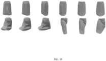
- PEN output vs ARAP deformed garment To demonstrate that PEN adds meaningful displacements to the ARAP deformed garment G to make it physically plausible, a displacement magnitude map is depicted in FIG. 14 . The garment and the underlying body shape and pose were same as in FIG. 6 . Maximum displacement magnitude produced by the PEN was 75mm. It was observed that PEN predicted the high magnitude of displacement for the vertices where the garment needs to displace due to the gravitational force, and where it falls on the body surface its magnitude becomes almost close to zero. Also, while producing the displacements for each vertex, PEN maintained the cloth quality. The rendered normal map of the template garment and the predicted garment were observed as in FIG. 15 .
- the embodiments of present disclosure herein address unresolved problem of generic garment simulation.
- the embodiment thus provides a method and system for generic garment simulation.
- the embodiments herein further provide a mechanism of generic garment simulation, using a combination of a body motion aware ARAP garment deformation and a Physics Enforcing Network (PEN).
- PEN Physics Enforcing Network
- Such computer-readable storage means contain program-code means for implementation of one or more steps of the method, when the program runs on a server or mobile device or any suitable programmable device.
- the hardware device can be any kind of device which can be programmed including e.g., any kind of computer like a server or a personal computer, or the like, or any combination thereof.
- the device may also include means which could be e.g., hardware means like e.g., an application-specific integrated circuit (ASIC), a field-programmable gate array (FPGA), or a combination of hardware and software means, e.g., an ASIC and an FPGA, or at least one microprocessor and at least one memory with software processing components located therein.
- the means can include both hardware means and software means.
- the method embodiments described herein could be implemented in hardware and software.
- the device may also include software means. Alternatively, the embodiments may be implemented on different hardware devices, e.g., using a plurality of CPUs.
- the embodiments herein can comprise hardware and software elements.
- the embodiments that are implemented in software include but are not limited to, firmware, resident software, microcode, etc.
- the functions performed by various components described herein may be implemented in other components or combinations of other components.
- a computer-usable or computer readable medium can be any apparatus that can comprise, store, communicate, propagate, or transport the program for use by or in connection with the instruction execution system, apparatus, or device.
- a computer-readable storage medium refers to any type of physical memory on which information or data readable by a processor may be stored.
- a computer-readable storage medium may store instructions for execution by one or more processors, including instructions for causing the processor(s) to perform steps or stages consistent with the embodiments described herein.
- the term "computer-readable medium” should be understood to include tangible items and exclude carrier waves and transient signals, i.e., be non-transitory. Examples include random access memory (RAM), read-only memory (ROM), volatile memory, nonvolatile memory, hard drives, CD ROMs, DVDs, flash drives, disks, and any other known physical storage media.
Landscapes
- Engineering & Computer Science (AREA)
- Physics & Mathematics (AREA)
- Theoretical Computer Science (AREA)
- General Physics & Mathematics (AREA)
- Geometry (AREA)
- General Engineering & Computer Science (AREA)
- Computer Hardware Design (AREA)
- Mathematical Analysis (AREA)
- Pure & Applied Mathematics (AREA)
- Evolutionary Computation (AREA)
- Mathematical Optimization (AREA)
- Computational Mathematics (AREA)
- Architecture (AREA)
- Computer Graphics (AREA)
- Software Systems (AREA)
- Processing Or Creating Images (AREA)
Abstract
State of the art approaches for 3D garment simulation approaches have the disadvantages that they 1) work on fixed garment type, 2) work on fixed body shapes, and 3) assume fixed garment topology. As a result, they do not offer a generic solution for garment simulation. Method and system disclosed herein use a combination of a body motion aware ARAP garment deformation and a Physics Enforcing Network (PEN), so as to generate garment simulations irrespective of garment type, body shapes, and garment topology, thus offering a generic solution.
Description
- The present application claims priority to
Indian application no. 202321038154, filed on June 2, 2023 - The disclosure herein generally relates to garment simulation, and, more particularly, to a method and system for generic garment simulation.
- Simulating 3D garments of varying types and sizes on 3D humans of arbitrary body shapes and poses is an important problem with direct applications in virtual try-on, garment authoring, garment catalog generation, etc. Although Physics-Based Simulation (PBS) approaches are preferable for accurate and realistic simulation of garments on 3D humans, they are computationally expensive and require expert intervention.
- Recently, there has been a growing interest in data-driven learning-based simulation approaches as they reduce dependency on experts, and the time complexity of the simulation significantly. However, they have several limitations. Many of these methods 1) Work on fixed garment type: for instance, Physically Based Neural Simulation (PBNS), Self-supervised Neural dynamic Garments (SNUG), VBones, and DD3DG can simulate only the garment template/type which is used for training thereby requiring a new model for each garment type. 2) Work on fixed body shapes: VBones and PBNS work on the fixed body shape used for training. 3) Assume fixed garment topology: methods such as Deep- Draper, and TailorNet assume different sizes of garments to have the same number of vertices, hence cannot model loose and long garments such as skirts and dresses, which require more number of vertices to accurately represent the geometry (wrinkles and folds). The existing supervised methods are trained primarily by minimizing L2 distance w.r.t the PBS data. Minimizing such L2 distance jointly for multiple tight and loose garments tends to learn average displacement and compromise the physical plausibility of the deformation.
- Embodiments of the present disclosure present technological improvements as solutions to one or more of the above-mentioned technical problems recognized by the inventors in conventional systems. For example, in one embodiment, a processor implemented method is provided. The method includes obtaining, via one or more hardware processors, a garment template, an initial body pose, and a target body pose, as input data. Further, the garment template is aligned via the one or more hardware processors, on the target body pose, by estimating a body motion-aware as-rigid-as-possible (ARAP) garment deformation from the obtained input data. Further, a per-vertex displacement of the garment template is determined, via the one or more hardware processors, using a Physics Enforcing Network (PEN) based on the obtained input data and the estimated body motion-aware ARAP garment deformation. The PEN is trained using a restrain energy loss, wherein computing the restrain energy loss comprises: estimating absolute difference between edge length in the garment template and an associated edge length in a deformed garment template obtained using the motion-aware ARAP, for all of a plurality of edges; and computing the restrain energy loss based on the estimated absolute difference. Further, a final deformed garment template is generated via the one or more hardware processors, for the target pose, by adding the determined per-vertex displacement of the garment template to the estimated body motion-aware ARAP garment deformation.
- In an embodiment of the method, estimating a body motion-aware as-rigid-as-possible (ARAP) garment deformation includes obtaining an index set of handle vertices of the garment template and associated displacement locations. Further, a displacement vector is computed for each handle vertex in the index set of handle vertices, with respect to position of the handle vertex indicated by the associated displacement location. Further, the following steps are performed for a pre-defined number of iterations: moving the handle vertices towards a final location in direction of the displacement vector, in a plurality of iterations; solving each non-handle vertex using ARAP; and solving collision of one or more of the handle vertices with body in the target body pose, comprising: identifying index of closest body vertex for each deformed non-handle vertex, and associated unit normal vector; identifying one or more collided vectors as projection of body to a garment vector onto the unit normal vector; and resolving identified collision by moving the one or more collided vectors towards a closest body vertex normal with a defined magnitude.
- In another embodiment, determining the per-vertex displacement of the garment template using the Physics Enforcing Network (PEN) includes the following steps. Initially, one or more latent features of the garment template and the initial body pose are obtained from a geometry encoder. Further, the one or more latent features are concatenated with a plurality of parameters to obtain concatenated feature vector. Further, a node feature vector is obtained by processing the concatenated feature vector using a node encoder. Further, a relative position of edge end-vertices in the garment template and estimated garment deformation are determined. Further, the determined relative position of edge end-vertices are encoded into an edge feature vector using an edge encoder. Further, an encoded garment graph is constructed using the node feature vector and edge feature vector. Further, an updated encoded garment graph is obtained by iteratively performing a message passing algorithm on the encoded garment graph, wherein every node aggregates one or more features from associated one or more incident edges, wherein the aggregated one or more features are processed to update own features, and are broadcasted to one or more neighboring nodes, and every edge node updates own features by taking the features from associated end nodes. Further, the per-vertex displacement of the garment template is determined by passing the updated garment graph through a displacement decoder.
- In another embodiment of the method, the plurality of parameters include a) a relative position of garment template vertex with respect to closest canonical pose body vertex, b) relative position of ARAP deformed garment template vertex with respect to closest target pose body vertex, c) a normal vector of the body vertex, d) a pin vertex indicator, e) a body motion vector, and f) a mass of the garment template vertex proportional to the area of associated faces.
- In another embodiment of the method, the restrain loss is computed as:

- ϕ ij represents an absolute edge length difference, wherein the absolute edge length difference is absolute difference between length of an edge in the garment template and associated edge length in the deformed garment template,
- µfabric is fabric specific mean of the absolute edge length difference, and
- σfabric is standard deviation of the absolute edge length difference.
- In another embodiment of the method, the initial body pose is a 3D human body in the canonical body pose.
- In yet another embodiment, a system is provided. The system includes one or more hardware processors, a communication interface, and a memory storing a plurality of instructions. The plurality of instructions when executed, cause the one or more hardware processors to obtain a garment template, an initial body pose, and a target body pose, as input data. Further, the garment template is aligned via the one or more hardware processors, on the target body pose, by estimating a body motion-aware as-rigid-as-possible (ARAP) garment deformation from the obtained input data. Further, a per-vertex displacement of the garment template is determined, via the one or more hardware processors, using a Physics Enforcing Network (PEN) based on the obtained input data and the estimated body motion-aware ARAP garment deformation. The PEN is trained using a restrain energy loss, wherein computing the restrain energy loss comprises: estimating absolute difference between edge length in the garment template and an associated edge length in a deformed garment template obtained using the motion-aware ARAP, for all of a plurality of edges; and computing the restrain energy loss based on the estimated absolute difference. Further, a final deformed garment template is generated via the one or more hardware processors, for the target pose, by adding the determined per-vertex displacement of the garment template to the estimated body motion-aware ARAP garment deformation.
- In yet another embodiment of the system, the one or more hardware processors are configured to estimate a body motion-aware as-rigid-as-possible (ARAP) garment deformation by obtaining an index set of handle vertices of the garment template and associated displacement locations. Further, a displacement vector is computed for each handle vertex in the index set of handle vertices, with respect to position of the handle vertex indicated by the associated displacement location. Further, the following steps are performed for a pre-defined number of iterations: moving the handle vertices towards a final location in direction of the displacement vector, in a plurality of iterations; solving each non-handle vertex using ARAP; and solving collision of one or more of the handle vertices with body in the target body pose, comprising: identifying index of closest body vertex for each deformed non-handle vertex, and associated unit normal vector; identifying one or more collided vectors as projection of body to a garment vector onto the unit normal vector; and resolving identified collision by moving the one or more collided vectors towards a closest body vertex normal with a defined magnitude.
- In yet another embodiment of the system, the one or more hardware processors are configured to determine the per-vertex displacement of the garment template using the Physics Enforcing Network (PEN), using the following steps. Initially, one or more latent features of the garment template and the initial body pose are obtained from a geometry encoder. Further, the one or more latent features are concatenated with a plurality of parameters to obtain concatenated feature vector. Further, a node feature vector is obtained by processing the concatenated feature vector using a node encoder. Further, a relative position of edge end-vertices in the garment template and estimated garment deformation are determined. Further, the determined relative position of edge end-vertices are encoded into an edge feature vector using an edge encoder. Further, an encoded garment graph is constructed using the node feature vector and edge feature vector. Further, an updated encoded garment graph is obtained by iteratively performing a message passing algorithm on the encoded garment graph, wherein every node aggregates one or more features from associated one or more incident edges, wherein the aggregated one or more features are processed to update own features, and are broadcasted to one or more neighboring nodes, and every edge node updates own features by taking the features from associated end nodes. Further, the per-vertex displacement of the garment template is determined by passing the updated garment graph through a displacement decoder.
- In another embodiment of the system, the plurality of parameters include a) a relative position of garment template vertex with respect to closest canonical pose body vertex, b) relative position of ARAP deformed garment template vertex with respect to closest target pose body vertex, c) a normal vector of the body vertex, d) a pin vertex indicator, e) a body motion vector, and f) a mass of the garment template vertex proportional to the area of associated faces.
- In another embodiment of the system, the one or more hardware processors are configured compute the restrain loss as:

- ϕ ij represents an absolute edge length difference, wherein the absolute edge length difference is absolute difference between length of an edge in the garment template and associated edge length in the deformed garment template,
- µfabric is fabric specific mean of the absolute edge length difference, and
- σfabric is standard deviation of the absolute edge length difference.
- In yet another embodiment of the system, the initial body pose is a 3D human body in the canonical body pose.
- In yet another embodiment, a non-transitory computer readable medium is provided. The non-transitory computer readable medium includes a plurality of instructions, which when executed, cause the one or more hardware processors to obtain a garment template, an initial body pose, and a target body pose, as input data. Further, the garment template is aligned via the one or more hardware processors, on the target body pose, by estimating a body motion-aware as-rigid-as-possible (ARAP) garment deformation from the obtained input data. Further, a per-vertex displacement of the garment template is determined, via the one or more hardware processors, using a Physics Enforcing Network (PEN) based on the obtained input data and the estimated body motion-aware ARAP garment deformation. The PEN is trained using a restrain energy loss, wherein computing the restrain energy loss comprises: estimating absolute difference between edge length in the garment template and an associated edge length in a deformed garment template obtained using the motion-aware ARAP, for all of a plurality of edges; and computing the restrain energy loss based on the estimated absolute difference. Further, a final deformed garment template is generated via the one or more hardware processors, for the target pose, by adding the determined per-vertex displacement of the garment template to the estimated body motion-aware ARAP garment deformation.
- In yet another embodiment, the non-transitory computer readable medium causes the one or more hardware processors to estimate a body motion-aware as-rigid-as-possible (ARAP) garment deformation by obtaining an index set of handle vertices of the garment template and associated displacement locations. Further, a displacement vector is computed for each handle vertex in the index set of handle vertices, with respect to position of the handle vertex indicated by the associated displacement location. Further, the following steps are performed for a pre-defined number of iterations: moving the handle vertices towards a final location in direction of the displacement vector, in a plurality of iterations; solving each non-handle vertex using ARAP; and solving collision of one or more of the handle vertices with body in the target body pose, comprising: identifying index of closest body vertex for each deformed non-handle vertex, and associated unit normal vector; identifying one or more collided vectors as projection of body to a garment vector onto the unit normal vector; and resolving identified collision by moving the one or more collided vectors towards a closest body vertex normal with a defined magnitude.
- In yet another embodiment, the non-transitory computer readable medium causes the one or more hardware processors to determine the per-vertex displacement of the garment template using the Physics Enforcing Network (PEN), based on the following steps. Initially, one or more latent features of the garment template and the initial body pose are obtained from a geometry encoder. Further, the one or more latent features are concatenated with a plurality of parameters to obtain concatenated feature vector. Further, a node feature vector is obtained by processing the concatenated feature vector using a node encoder. Further, a relative position of edge end-vertices in the garment template and estimated garment deformation are determined. Further, the determined relative position of edge end-vertices are encoded into an edge feature vector using an edge encoder. Further, an encoded garment graph is constructed using the node feature vector and edge feature vector. Further, an updated encoded garment graph is obtained by iteratively performing a message passing algorithm on the encoded garment graph, wherein every node aggregates one or more features from associated one or more incident edges, wherein the aggregated one or more features are processed to update own features, and are broadcasted to one or more neighboring nodes, and every edge node updates own features by taking the features from associated end nodes. Further, the per-vertex displacement of the garment template is determined by passing the updated garment graph through a displacement decoder.
- In yet another embodiment of the non-transitory computer readable medium, the plurality of parameters include a) a relative position of garment template vertex with respect to closest canonical pose body vertex, b) relative position of ARAP deformed garment template vertex with respect to closest target pose body vertex, c) a normal vector of the body vertex, d) a pin vertex indicator, e) a body motion vector, and f) a mass of the garment template vertex proportional to the area of associated faces.
- In yet another embodiment, the non-transitory computer readable medium causes the one or more hardware processors to compute the restrain loss as:

- ϕ ij represents an absolute edge length difference, wherein the absolute edge length difference is absolute difference between length of an edge in the garment template and associated edge length in the deformed garment template,
- µfabric is fabric specific mean of the absolute edge length difference, and
- σfabric is standard deviation of the absolute edge length difference.
- In yet another embodiment of the non-transitory computer readable medium, the initial body pose is a 3D human body in the canonical body pose.
- It is to be understood that both the foregoing general description and the following detailed description are exemplary and explanatory only and are not restrictive of the invention, as claimed.
- The accompanying drawings, which are incorporated in and constitute a part of this disclosure, illustrate exemplary embodiments and, together with the description, serve to explain the disclosed principles:
-
FIG. 1 illustrates an exemplary system for generic garment simulation, according to some embodiments of the present disclosure. -
FIG. 2 is a flow diagram depicting steps involved in the process of the generic garment simulation, by the system ofFIG. 1 , according to some embodiments of the present disclosure. -
FIG. 3 is a flow diagram depicting steps involved in the process of estimating a body motion-aware as-rigid-as-possible (ARAP) garment deformation, by the system ofFIG. 1 , in accordance with some embodiments of the present disclosure. -
FIG. 4 is a flow diagram depicting steps involved in the process of solving collision of one or more of the handle vertices with body in the target body pose, by the system ofFIG. 1 , according to some embodiments of the present disclosure. -
FIGS. 5A and5B (collectively referred to asFIG. 5 ) is a flow diagram depicting steps involved in the process of determining the per-vertex displacement of the garment template using the Physics Enforcing Network (PEN), by the system ofFIG. 1 , in accordance with some embodiments of the present disclosure. -
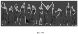
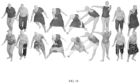
FIGS. 6 through 15 depict examples figures associated with the process of the generic garment simulation by the system ofFIG. 1 , according to some embodiments of the present disclosure. - Exemplary embodiments are described with reference to the accompanying drawings. In the figures, the left-most digit(s) of a reference number identifies the figure in which the reference number first appears. Wherever convenient, the same reference numbers are used throughout the drawings to refer to the same or like parts. While examples and features of disclosed principles are described herein, modifications, adaptations, and other implementations are possible without departing from the scope of the disclosed embodiments.
- Some of the state of the art approaches for 3D garment simulation are data-driven learning-based simulation approaches as they reduce dependency on experts, and the time complexity of the simulation significantly. However, they have several limitations. Many of these methods 1) Work on fixed garment type: for instance Physically Based Neural Simulation (PBNS), Self-supervised Neural dynamic Garments (SNUG), VBones, and DD3DG can simulate only the garment template/type which is used for training thereby requiring a new model for each garment type. 2) Work on fixed body shapes: VBones and PBNS work on the fixed body shape used for training. 3) Assume fixed garment topology: methods such as Deep- Draper, and TailorNet assume different sizes of garments to have the same number of vertices, hence cannot model loose and long garments such as skirts and dresses, which require more number of vertices to accurately represent the geometry (wrinkles and folds). The existing supervised methods are trained primarily by minimizing L2 distance w.r.t the PBS data. Minimizing such L2 distance jointly for multiple tight and loose garments tends to learn average displacement and compromise the physical plausibility of the deformation.
- To address these challenges, a method and system for generic garment simulation are provided. The method includes obtaining a garment template, an initial body pose, and a target body pose, as input data. Further, the garment template is aligned on the target body pose, by estimating a body motion-aware as-rigid-as-possible (ARAP) garment deformation from the obtained input data. Further, a per-vertex displacement of the garment template is determined using a Physics Enforcing Network (PEN) based on the obtained input data and the estimated body motion-aware ARAP garment deformation. The PEN is trained using a restrain energy loss. Computing the restrain energy loss comprises: estimating absolute difference between edge length in the garment template and an associated edge length in a deformed garment template obtained using the motion-aware ARAP, for all of a plurality of edges; and computing the restrain energy loss based on the estimated absolute difference. Further, a final deformed garment template is generated via the one or more hardware processors, for the target pose, by adding the determined per-vertex displacement of the garment template to the estimated body motion-aware ARAP garment deformation.
- Referring now to the drawings, and more particularly to
FIG. 1 through FIG. 15 , where similar reference characters denote corresponding features consistently throughout the figures, there are shown preferred embodiments and these embodiments are described in the context of the following exemplary system and/or method. -
FIG. 1 illustrates an exemplary system for generic garment simulation, according to some embodiments of the present disclosure. - The
system 100 includes or is otherwise in communication withhardware processors 102, at least one memory such as amemory 104, an I/O interface 112. Thehardware processors 102,memory 104, and the Input /Output (I/O)interface 112 may be coupled by a system bus such as asystem bus 108 or a similar mechanism. In an embodiment, thehardware processors 102 can be one or more hardware processors. - The I/
O interface 112 may include a variety of software and hardware interfaces, for example, a web interface, a graphical user interface, and the like. The I/O interface 112 may include a variety of software and hardware interfaces, for example, interfaces for peripheral device(s), such as a keyboard, a mouse, an external memory, a printer and the like. Further, the I/O interface 112 may enable thesystem 100 to communicate with other devices, such as web servers, and external databases. - The I/
O interface 112 can facilitate multiple communications within a wide variety of networks and protocol types, including wired networks, for example, local area network (LAN), cable, etc., and wireless networks, such as Wireless LAN (WLAN), cellular, or satellite. For the purpose, the I/O interface 112 may include one or more ports for connecting several computing systems with one another or to another server computer. The I/O interface 112 may include one or more ports for connecting several devices to one another or to another server. - The one or
more hardware processors 102 may be implemented as one or more microprocessors, microcomputers, microcontrollers, digital signal processors, central processing units, node machines, logic circuitries, and/or any devices that manipulate signals based on operational instructions. Among other capabilities, the one ormore hardware processors 102 is configured to fetch and execute computer-readable instructions stored in thememory 104. - The
memory 104 may include any computer-readable medium known in the art including, for example, volatile memory, such as static random-access memory (SRAM) and dynamic random-access memory (DRAM), and/or non-volatile memory, such as read only memory (ROM), erasable programmable ROM, flash memories, hard disks, optical disks, and magnetic tapes. In an embodiment, thememory 104 includes a plurality ofmodules 106. - The plurality of
modules 106 include programs or coded instructions that supplement applications or functions performed by thesystem 100 for executing different steps involved in the process of generic garment simulation, being performed by thesystem 100. The plurality ofmodules 106, amongst other things, can include routines, programs, objects, components, and data structures, which performs particular tasks or implement particular abstract data types. The plurality ofmodules 106 may also be used as, signal processor(s), node machine(s), logic circuitries, and/or any other device or component that manipulates signals based on operational instructions. Further, the plurality ofmodules 106 can be used by hardware, by computer-readable instructions executed by the one ormore hardware processors 102, or by a combination thereof. The plurality ofmodules 106 can include various sub-modules (not shown). The plurality ofmodules 106 may include computer-readable instructions that supplement applications or functions performed by thesystem 100 for the generic garment simulation. - The data repository (or repository) 110 may include a plurality of abstracted piece of code for refinement and data that is processed, received, or generated as a result of the execution of the plurality of modules in the module(s) 106.
- Although the
data repository 110 is shown internal to thesystem 100, it will be noted that, in alternate embodiments, thedata repository 110 can also be implemented external to thesystem 100, where thedata repository 110 may be stored within a database (repository 110) communicatively coupled to thesystem 100. The data contained within such external database may be periodically updated. For example, new data may be added into the database (not shown inFIG. 1 ) and/or existing data may be modified and/or non-useful data may be deleted from the database. In one example, the data may be stored in an external system, such as a Lightweight Directory Access Protocol (LDAP) directory and a Relational Database Management System (RDBMS). Functions of the components of thesystem 100 are now explained with reference to the steps in flow diagrams inFIG. 2 ,FIG. 3 ,FIG. 4 , andFIG. 5 , and the example figures fromFIG. 6 through FIG. 15 . -
FIG. 2 is a flow diagram depicting steps involved in the process of the generic garment simulation, by the system ofFIG. 1 , according to some embodiments of the present disclosure. - In an embodiment, the
system 100 comprises one or more data storage devices or thememory 104 operatively coupled to the processor(s) 102 and is configured to store instructions for execution of steps of amethod 200 by the processor(s) or one ormore hardware processors 102. The steps of themethod 200 of the present disclosure will now be explained with reference to the components or blocks of thesystem 100 as depicted inFIG. 1 and the steps of flow diagram as depicted inFIG. 2 . Although process steps, method steps, techniques or the like may be described in a sequential order, such processes, methods, and techniques may be configured to work in alternate orders. In other words, any sequence or order of steps that may be described does not necessarily indicate a requirement that the steps to be performed in that order. The steps of processes described herein may be performed in any order practical. Further, some steps may be performed simultaneously. - At
step 202 ofmethod 200 ofFIG. 2 , thesystem 100 obtains, via the one ormore hardware processors 102, a garment template, an initial body pose, and a target body pose , as input data.
- Further, at
step 204 of themethod 200, the garment template is aligned via the one or more hardware processors, on the target body pose, by estimating a body motion-aware as-rigid-as-possible (ARAP) garment deformation from the obtained input data. Steps involved in the process of aligning the garment template on the target body pose, using the motion-aware ARAP are depicted inmethod 300 inFIG. 3 and are explained hereafter. - The motion-aware ARAP deforms the garment in the presence of the human body as an obstacle. The handle vertices considered in this process are garment vertices under direct influence of the force exerted by the motion of the underlying body. At
step 302 of themethod 300, thesystem 100 indexes of the handle vertices of the garment in the setand associated displaced locations , ∀i ∈
 are obtained as input. Values of
 and
and are obtained as explained below.
- Letand
 contain the vertices of the body in the initial and the target body poses respectively, and ω is an index set of the garment pin vertices. The
system 100 finds a relative motiondi of a body vertex closest to each template garment vertex. Similarly, thesystem 100 computes the relative position vector ui of the template garment vertex with respect to the closest body vertex. The angle between di and ui indicates the set of garment vertices that are under the direct influence of the force due to the body motion. Locations of handle vertices are computed by moving them along the direction of motion with a magnitude (∥d∥ - q). Further thesystem 100 moves the garment pin vertices such that their relative positions with respect to the body surface pin area remains approximately the same. Thesystem 100 then updates the handle vertices index setby adding pin vertices to that set so that the location of pin vertices are not changed.
- Further, at
step 304 of themethod 300, thesystem 100 computes a displacement vectorgi for each ith handle vertex in the index set of handle vertices, with respect to position of the handle vertex indicated by the associated displacement location. - Further, at
step 306 of themethod 300, thesystem 100 performs substeps 306a through 306c for a pre-defined number of iterations. Atstep 306a, thesystem 100 moves the handle vertices towards a final location in direction of the displacement vector, in a plurality of iterations. The movement in each iteration is according to a step size t, which may be a pre-defined value. Atstep 306b, thesystem 100 solves each non-handle vertex using ARAP, i.e. using state of the art ARAP technique. Further, thesystem 100 determines if any of the non-handle vertices collide with the target body. If any of the non-handle vertices is found to be colliding with the target body, atstep 306c, thesystem 100 solves the identified collision. Various steps in the process of solving the identified solution are depicted inmethod 400 inFIG. 4 , and are explained hereafter. - At
step 402 of themethod 400, thesystem 100 identifies index vi of closest body vertex for each deformed non-handle vertex
i . Here, projection of the body to the garment vector onto the unit normal vector can indicate the collided vertices, as depicted instep 404 of themethod 400. Further, atstep 406 of themethod 400, thesystem 100 resolves the identified collision by moving the one or more collided vectors towards a closest body vertex normal n̂vi with a defined magnitude |δ|. In the iterative movement as explained in themethod 400, values of the total number of iterations, and the step size in each iteration are pre-defined. - Referring back to the
method 200, the obtained Body Motion-aware ARAP deformed garment may not be physically plausible as it is deformed under as-rigid-as-possible constraints. To make it physically plausible, atstep 206 of themethod 200, thesystem 100 uses a Physics Enforcing Network (PEN) which determines a displacement or correction for every vertex (i.e. per-vertex displacement), which is then added to make the ARAP deformed garment physically plausible. Various steps in the process of determining the per-vertex displacement of the garment template using the PEN are depicted inmethod 500 inFIG. 5 , and are explained hereafter. - The physical plausibility of the deformed garment depends on several factors such as the shape and size of the template garment, the body motion, etc. Such features are encoded into the garment graph node feature. Similarly, the relative position of the edge end-vertices of the garment mesh are encoded into the edge features of the garment graph.
- At
step 502 of themethod 500, thesystem 100 obtains one or more latent features of the garment template and the initial body pose, from a geometry encoder. Let ηi and πl denote the ith and lth latent node and edge feature vectors of the encoded garment graph respectively. Process of obtaining the one or more latent features is explained below. - In this process, geometry of each vertex of the template garment and the underlying body mesh are encoded using a geometry encoder. Let

 . The latent geometric feature vectors are concatenated with the relative position of garment vertex w.r.t its closest canonical pose body vertex
ui =- , the relative position of ARAP deformed garment vertex w.r.t its closest target pose body vertex
 = Gi -
 , the normal vector n̂i of the body vertex
 , the pin vertex indicator
 (
( = 1 for pin vertices, else 0), the body motion vector di , and the mass
 of the garment vertex, which is proportional to the area of its associated faces. The concatenated input

- Similarly, the latent edge features are obtained as below.
- Relative position of edge end vertices inand
 are determined as εij =
 -
- and
and


- Further, at
step 504 of themethod 500, thesystem 100 concatenates one or more latent features with a plurality of parameters to obtain concatenated feature vector. The plurality of parameters include a) a relative position of garment template vertex with respect to closest canonical pose body vertex, b) relative position of ARAP deformed garment template vertex with respect to closest target pose body vertex, c) a normal vector of the body vertex, d) a pin vertex indicator, e) a body motion vector, and f) a mass of the garment template vertex proportional to the area of associated faces. Further, atstep 506 of themethod 500, thesystem 100 obtains a node feature vector by processing the concatenated feature vector using a node encoder. Further, atstep 508 of themethod 500, thesystem 100 determines a relative position of edge end-vertices in the garment template and estimated garment deformation. Further, atstep 510 of themethod 500, thesystem 100 encodes the determined relative position of edge end-vertices into an edge feature vector using an edge encoder. Further, atstep 512 of themethod 500, thesystem 100 constructs an encoded garment graph using the node feature vector and edge feature vector. - Further, at
step 514 of themethod 500, an updated encoded garment graph is obtained by iteratively performing a message passing algorithm on the encoded garment graph, wherein every node aggregates one or more features from associated one or more incident edges, wherein the aggregated one or more features are processed to update own features, and are broadcasted to one or more neighboring nodes, and every edge node updates own features by taking the features from associated end nodes. The message passing is repeated for L steps. - Further, at
step 516 of themethod 500, the per-vertex displacement of the garment template is determined by passing the updated garment graph through a displacement decoder. The final encoded garment graph node features are used by the displacement decoder to produce per vertex direction D̂ and the magnitude ω of the displacement, which is added to the ARAP deformed garment vertices so that the final garment deformation becomes physically plausible. The final predicted deformed garment
- To ensure that the direction of displacement D̂ of a garment vertex
 , it is restricted to be outwards to the local body surface patch, i.e. in the half-space towards the unit normal n̂i of the body vertex
 . Value of D̂ can be obtained as a convex combination of vectors n̂ and b̂ . Let [b 1 , b 2 , b 3] are coefficients of
b , and b̂ =b /∥b ∥. Asb may be orthogonal ton ,n .b = 0. Hence,
- The displacement decoder predicts the values of b 1 , b 2 , a convex combination factor ρ , and the magnitude of displacement ω for each garment vertex. The coefficient b 3 of the direction vector can be estimated from b 1 and b 2 as above. The unit direction vectoris then obtained as
 =
= , where
 is estimated as:

- Where, ρ is output of Tanh activation, hence |ρ| is used to ensure the convex combination (0 ≤ |ρ| ≤ 1) of n̂ and b̂ . To consider both b̂ and -b̂ as valid solutions, b̂ is multiplied with

- Referring back to the
method 200, atstep 208 of themethod 200, thesystem 100 generates a final deformed garment template is generated via the one or more hardware processors, for the target pose, by adding the determined per-vertex displacement of the garment template to the estimated body motion-aware ARAP garment deformation. - In an embodiment, the PEN is trained using a restrain energy loss. Computing the restrain energy loss includes the following steps. Initially, an absolute difference between edge length in the garment template and an associated edge length in a deformed garment template obtained using the motion-aware ARAP is estimated for all of a plurality of edges. Further, the restrain energy loss is computed based on the estimated absolute difference. The restrain loss is computed as:

- In an embodiment, the
system 100 may compute a total training loss of the PEN as a sum of the restrain energy loss with a bending energy, a pin vertices loss, a potential energy, a mesh smoothness loss, and a garment-to-body-collision penalty loss. Details of calculation of each of these parameters is given below: - Bending Energy: The bending loss term measures the energy due to the angle between two adjacent garment faces, and is modelled as:
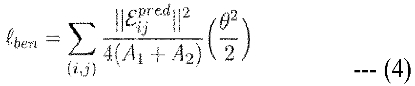
where, A 1 and A 2 are the areas of the adjacent faces, εij pred is the common edge connecting two adjacent faces, and θ is the dihedral angle between the adjacent faces. - Pin Vertices Loss: The movement of the pin vertices are restricted from their respective location in the ARAP deformed garment G , which prevents the garment from falling down. L2 regularization loss is applied between vertices in G and G pred. Here, ω is the index set of pin vertices.

- Potential Energy: The potential energy loss term measures the energy due to the gravitational force, which is modeled as below, where g is the gravitational acceleration, zi is the height of the final deformed garment vertex Gi pred , and M i is the mass of the garment vertex. The potential energy loss for all the non-pin vertices is computed.

- Mesh Smoothness Loss: To enforce locally smooth surfaces of predicted garment mesh G pred , the
system 100 applies Laplacian smoothing loss with cotangent weights. Here, △ is the Laplacian smoothing operator.
- Garment-to-Body Collision Penalty Loss: The direction of displacement used by the
system 100, by design avoids collisions locally. However, if the garment vertex needs to move a lot i.e., when the magnitude of the displacement is large, in such cases the vertex may collide with the non-local body surfaces. This happens mainly when the garment lies between the two body parts, where the normal of both the body parts are facing each other (e.g., the garment lies between the folded leg i.e., between the back side of the thigh and the calf muscle body area). To handle those scenarios thesystem 100 applies a garment-to-body collision penalty loss as: is the body vertex closest to the final deformed garment vertex
 . εcoll is the collision threshold for robustness.
- Further, the total loss L is calculated as:

- For the experiments, the
system 100 was trained on a subset of 175 sequences with tops and skirts outfits from the training split of the CLOTH3D dataset and was tested on 60 sequences from the test split from this dataset. - Quantitative: To demonstrate performance of data model used by the
system 100, for predicting more accurate physically plausible garment deformations, two variants, one with unsupervised losses, and another using L2 loss on predicted garment vertices, were used. Both variants were compared on the test set using metrics for average edge compression/elongation with respect to their length in the template garment, garment surface quality smoothness measured using the Laplacian loss term used in calculation of the mesh smoothness loss, and the percentage of garment vertices collisions with the body. As the per results in Table 1, the variant trained with physics-based losses appeared to be producing better quality garment deformations owing to lower edge distortion, smoother garment surfaces, and significantly lower body-to-garment collision. In the first variant, the L2 loss learns the ground-truth data in an average sense, which leads to elongation/compression of some edges and collisions. On the other hand, unsupervised losses in thesystem 100 compute the garment deformation that reduces the overall energy of the garment, while restraining edge lengths from changing too much, and also avoiding collisions, thereby, producing better results.Table 1. Quantitative Evaluation on CLOTH3D Test Set Training Strategy Edge (mm) Smoothness Collision (%) Supervised L2 + 3.8 0.0013 10.1 Smoothness + Collision Loss Unsupervised Losses Physics 1.9 0.0008 0.6 - Qualitative: Sample qualitative results of the
method 200 on various unseen body shapes, poses, and garments of various types, sizes, and topologies are shown inFIG. 9a . Themethod 200 produced physically plausible simulations. - Comparison with PBNS, and DeePSD: Results of these different approaches were qualitatively compared with PBNS and DeePSD on CLOTH3D test samples. Since PBNS is an outfit-body specific method, the two PBNS models were trained one for each outfit-body pair in (a) and (h) in
FIG. 9b . DeePSD was trained on the same training set of tops and skirts as themethod 200. Note: For PBNS both the training and testing garment template is the same, whereas the testing garment template is unseen for both DeePSD andMethod 200 during training. DeePSD suffered from collisions (in © and (j) inFIG. 9b ), PBNS produced similar artifacts for skirts (between legs) as in (d) and (k) inFIG. 9b . - Generalization capability of the
method 200 was evaluated by evaluating it on unseen garment types (dress, t-shirt, pant, shorts, tank) of different topologies from a VTO-dataset. The results shown inFIG. 10 show that despite being trained only on tops and skirts themethod 200 generalized well on unseen garments. Qualitative comparison with VTOCOLL is depicted inFIG. 11 . - On a random YouTube® video: Results of the
method 200 draping unseen garments (pants, shorts, dress, and tank) on unseen body shapes and poses in a frame of random YouTube video is depicted inFIG. 12 . PARE was used to estimate the body shape and pose of humans from the image. - For the experiment, the
method 200 was implemented using PyTorch. PointNet was used for the geometry encoders, the node and the edge feature encoders were MLPs. Themethod 200 was trained using adam optimizer for 30 epochs with an iniγ2 = γ5 = 1.0, ε = -0.5 and ε coll = 0.003. The model size used in themethod 200 was ~ 1MB. Themethod 200 was found to be taking average ∼ 0.9 secs [0.6(ARAP)+ 0.3(PEN)] for inferring a 3000 vertices skirt as compared to on average 5 minutes taken by a physics based simulator ArcSim, similar time of ArcSim. The simulation of a garment on a static body pose is invariant to the global body rotation and position. Hence the target body pose was front aligned with respect to the template body pose (T-pose) by removing any global rotation and translation with respect to the T-pose body root joint. - Losses Justification: It is well understood that Laplacian and the bending losses are important for maintaining the quality of garment surfaces. Effect of potential energy loss, pin loss and restrain loss were studied during the experiments. Three variants of PEN were trained on a small subset of 10 random sequences of a short skirt. V1:(ℓ pe +ℓ ben +ℓ sm ), this variant was trained with potential energy loss (ℓ pe ), Laplacian smoothing loss (ℓ sm ), and bending loss (ℓ ben ), V2: in addition to all the losses of V1, the pin loss (ℓ pin ) was added, and in V3:, restrain loss ((ℓ str ) was added to the V2 losses. It was observed in
FIG. 13 , that in the V1 version, since the gravitation force was the only force acting on the vertices it led to the fall down of the garment. The V2 version held the garment with the pin vertices, however, the dominating gravitation energy pulled the vertices downwards which resulted in arbitrary elongation of the edges. The third version V3 with additional restrain loss, restrict edges to elongate arbitrarily due to the influence of the gravitation force. This demonstrates all the losses are important and necessary to train PEN in an unsupervised manner. - PEN output vs ARAP deformed garment: To demonstrate that PEN adds meaningful displacements to the ARAP deformed garment G to make it physically plausible, a displacement magnitude map is depicted in
FIG. 14 . The garment and the underlying body shape and pose were same as inFIG. 6 . Maximum displacement magnitude produced by the PEN was 75mm. It was observed that PEN predicted the high magnitude of displacement for the vertices where the garment needs to displace due to the gravitational force, and where it falls on the body surface its magnitude becomes almost close to zero. Also, while producing the displacements for each vertex, PEN maintained the cloth quality. The rendered normal map of the template garment and the predicted garment were observed as inFIG. 15 . - The written description describes the subject matter herein to enable any person skilled in the art to make and use the embodiments. The scope of the subject matter embodiments is defined by the claims and may include other modifications that occur to those skilled in the art. Such other modifications are intended to be within the scope of the claims if they have similar elements that do not differ from the literal language of the claims or if they include equivalent elements with insubstantial differences from the literal language of the claims.
- The embodiments of present disclosure herein address unresolved problem of generic garment simulation. The embodiment, thus provides a method and system for generic garment simulation. Moreover, the embodiments herein further provide a mechanism of generic garment simulation, using a combination of a body motion aware ARAP garment deformation and a Physics Enforcing Network (PEN).
- It is to be understood that the scope of the protection is extended to such a program and in addition to a computer-readable means having a message therein; such computer-readable storage means contain program-code means for implementation of one or more steps of the method, when the program runs on a server or mobile device or any suitable programmable device. The hardware device can be any kind of device which can be programmed including e.g., any kind of computer like a server or a personal computer, or the like, or any combination thereof. The device may also include means which could be e.g., hardware means like e.g., an application-specific integrated circuit (ASIC), a field-programmable gate array (FPGA), or a combination of hardware and software means, e.g., an ASIC and an FPGA, or at least one microprocessor and at least one memory with software processing components located therein. Thus, the means can include both hardware means and software means. The method embodiments described herein could be implemented in hardware and software. The device may also include software means. Alternatively, the embodiments may be implemented on different hardware devices, e.g., using a plurality of CPUs.
- The embodiments herein can comprise hardware and software elements. The embodiments that are implemented in software include but are not limited to, firmware, resident software, microcode, etc. The functions performed by various components described herein may be implemented in other components or combinations of other components. For the purposes of this description, a computer-usable or computer readable medium can be any apparatus that can comprise, store, communicate, propagate, or transport the program for use by or in connection with the instruction execution system, apparatus, or device.
- The illustrated steps are set out to explain the exemplary embodiments shown, and it should be anticipated that ongoing technological development will change the manner in which particular functions are performed. These examples are presented herein for purposes of illustration, and not limitation. Further, the boundaries of the functional building blocks have been arbitrarily defined herein for the convenience of the description. Alternative boundaries can be defined so long as the specified functions and relationships thereof are appropriately performed. Alternatives (including equivalents, extensions, variations, deviations, etc., of those described herein) will be apparent to persons skilled in the relevant art(s) based on the teachings contained herein. Such alternatives fall within the scope of the disclosed embodiments. Also, the words "comprising," "having," "containing," and "including," and other similar forms are intended to be equivalent in meaning and be open ended in that an item or items following any one of these words is not meant to be an exhaustive listing of such item or items, or meant to be limited to only the listed item or items. It must also be noted that as used herein and in the appended claims, the singular forms "a," "an," and "the" include plural references unless the context clearly dictates otherwise.
- Furthermore, one or more computer-readable storage media may be utilized in implementing embodiments consistent with the present disclosure. A computer-readable storage medium refers to any type of physical memory on which information or data readable by a processor may be stored. Thus, a computer-readable storage medium may store instructions for execution by one or more processors, including instructions for causing the processor(s) to perform steps or stages consistent with the embodiments described herein. The term "computer-readable medium" should be understood to include tangible items and exclude carrier waves and transient signals, i.e., be non-transitory. Examples include random access memory (RAM), read-only memory (ROM), volatile memory, nonvolatile memory, hard drives, CD ROMs, DVDs, flash drives, disks, and any other known physical storage media.
- It is intended that the disclosure and examples be considered as exemplary only, with a true scope of disclosed embodiments being indicated by the following claims.
Claims (15)
- A processor implemented method (200), comprising:obtaining (202), via one or more hardware processors, a garment template, an initial body pose, and a target body pose, as input data;aligning (204), via the one or more hardware processors, the garment template on the target body pose, by estimating a body motion-aware as-rigid-as-possible (ARAP) garment deformation from the obtained input data;determining (206), via the one or more hardware processors, a per-vertex displacement of the garment template using a Physics Enforcing Network (PEN) based on the obtained input data and the estimated body motion-aware ARAP garment deformation, wherein the PEN is trained using a restrain energy loss, wherein computing the restrain energy loss comprises:estimating (206a) absolute difference between an edge length in the garment template and an associated edge length in a deformed garment template obtained using the motion-aware ARAP, for all of a plurality of edges; andcomputing (206b) the restrain energy loss based on the estimated absolute difference; andgenerating (208), via the one or more hardware processors, a final deformed garment template for the target pose, by adding the determined per-vertex displacement of the garment template to the estimated body motion-aware ARAP garment deformation.
- The method as claimed in claim 1, wherein estimating the body motion-aware as-rigid-as-possible (ARAP) garment deformation comprises:obtaining (302) an index set of handle vertices of the garment template and associated displacement locations;computing (304) a displacement vector for each handle vertex in the index set of handle vertices, with respect to position of the handle vertex indicated by the associated displacement location; andperforming (306) for a pre-defined number of iterations:moving the handle vertices towards a final location in direction of the displacement vector, in a plurality of iterations;solving each non-handle vertex using ARAP; andsolving collision of one or more of the handle vertices with body in the target body pose, comprising:identifying (402) index of closest body vertex for each deformed non-handle vertex, and associated unit normal vector;identifying (404) one or more collided vectors as projection of body to a garment vector onto the unit normal vector; andresolving (406) identified collision by moving the one or more collided vectors towards a closest body vertex normal with a defined magnitude.
- The method as claimed in claim 1, wherein determining the per-vertex displacement of the garment template using the Physics Enforcing Network (PEN) comprises:obtaining (502) one or more latent features of the garment template andthe initial body pose from a geometry encoder;concatenating (504) the one or more latent features with a plurality of parameters to obtain concatenated feature vector;obtaining (506) a node feature vector by processing the concatenated feature vector using a node encoder;determining (508) a relative position of edge end-vertices in the garment template and estimated garment deformation;encoding (510) the determined relative position of edge end-vertices into an edge feature vector using an edge encoder;constructing (512) an encoded garment graph using the node feature vector and edge feature vector;obtaining (514) an updated encoded garment graph by iteratively performing a message passing algorithm on the encoded garment graph,wherein every node aggregates one or more features from associated one or more incident edges, wherein the aggregated one or more features are processed to update own features, and are broadcasted to one or more neighboring nodes, and every edge node updates own features by taking the features from associated end nodes; anddetermining (516) the per-vertex displacement of the garment template by passing the updated garment graph through a displacement decoder.
- The method as claimed in claim 3, wherein the plurality of parameters include a) a relative position of garment template vertex with respect to closest canonical pose body vertex, b) relative position of ARAP deformed garment template vertex with respect to closest target pose body vertex, c) a normal vector of the body vertex, d) a pin vertex indicator, e) a body motion vector, and f) a mass of the garment template vertex proportional to the area of associated faces.
- The method as claimed in claim 1, wherein the restrain loss is computed as:
 ϕ ij represents an absolute edge length difference, wherein the absolute edge length difference is absolute difference between length of an edge in the garment template and associated edge length in the deformed garment template,µfabric is fabric specific mean of the absolute edge length difference, andσfabric is standard deviation of the absolute edge length difference.
 - The method as claimed in claim 1, wherein the initial body pose is a 3D human body in the canonical body pose.
- A system, comprising:one or more hardware processors;a communication interface; anda memory storing a plurality of instructions, wherein the plurality of instructions cause the one or more hardware processors to:obtain a garment template, an initial body pose, and a target body pose, as input data;align the garment template on the target body pose, by estimating a body motion-aware as-rigid-as-possible (ARAP) garment deformation from the obtained input data;determine a per-vertex displacement of the garment template using a Physics Enforcing Network (PEN) based on the obtained input data and the estimated body motion-aware ARAP garment deformation, wherein the PEN is trained using a restrain energy loss, wherein computing the restrain energy loss comprises:estimating absolute difference between an edge length in the garment template and an associated edge length in a deformed garment template obtained using the motion-aware ARAP, for all of a plurality of edges; andcomputing the restrain energy loss based on the estimated absolute difference; andgenerate a final deformed garment template for the target pose, by adding the determined per-vertex displacement of the garment template to the estimated body motion-aware ARAP garment deformation.
- The system as claimed in claim 7, wherein the one or more hardware processors are configured to estimate the body motion-aware as-rigid-as-possible (ARAP) garment deformation, by:obtaining an index set of handle vertices of the garment template andassociated displacement locations;computing a displacement vector for each handle vertex in the index set of handle vertices, with respect to position of the handle vertex indicated by the associated displacement location; andperforming for a pre-defined number of iterations:moving the handle vertices towards a final location in direction of the displacement vector, in a plurality of iterations;solving each non-handle vertex using ARAP; andsolving collision of one or more of the handle vertices with body in the target body pose, comprising:identifying index of closest body vertex for each deformed non-handle vertex, and associated unit normal vector;identifying one or more collided vectors as projection of body to a garment vector onto the unit normal vector; andresolving identified collision by moving the one or more collided vectors towards a closest body vertex normal with a defined magnitude.
- The system as claimed in claim 7, wherein the one or more hardware processors are configured to determine the per-vertex displacement of the garment template using the Physics Enforcing Network (PEN), by:obtaining one or more latent features of the garment template and the initial body pose from a geometry encoder;concatenating the one or more latent features with a plurality of parameters to obtain concatenated feature vector;obtaining a node feature vector by processing the concatenated feature vector using a node encoder;determining a relative position of edge end-vertices in the garment template and estimated garment deformation;encoding the determined relative position of edge end-vertices into an edge feature vector using an edge encoder;constructing an encoded garment graph using the node feature vector and edge feature vector;obtaining an updated encoded garment graph by iteratively performing a message passing algorithm on the encoded garment graph, wherein every node aggregates one or more features from associated one or more incident edges, wherein the aggregated one or more features are processed to update own features, and are broadcasted to one or more neighboring nodes, and every edge node updates own features by taking the features from associated end nodes; anddetermining the per-vertex displacement of the garment template by passing the updated garment graph through a displacement decoder.
- The system as claimed in claim 9, wherein the plurality of parameters include a) a relative position of garment template vertex with respect to closest canonical pose body vertex, b) relative position of ARAP deformed garment template vertex with respect to closest target pose body vertex, c) a normal vector of the body vertex, d) a pin vertex indicator, e) a body motion vector, and f) a mass of the garment template vertex proportional to the area of associated faces.
- The system as claimed in claim 7, wherein the one or more hardware processors are configured to compute the restrain loss as:
 ϕ ij represents an absolute edge length difference, wherein the absolute edge length difference is absolute difference between length of an edge in the garment template and associated edge length in the deformed garment template,µfabric is fabric specific mean of the absolute edge length difference, andσfabric is standard deviation of the absolute edge length difference.
 - The system as claimed in claim 7, wherein the initial body pose is a 3D human body in the canonical body pose.
- One or more non-transitory machine-readable information storage mediums comprising one or more instructions which when executed by one or more hardware processors cause:obtaining a garment template, an initial body pose, and a target body pose, as input data;aligning the garment template on the target body pose, by estimating a body motion-aware as-rigid-as-possible (ARAP) garment deformation from the obtained input data;determining a per-vertex displacement of the garment template using a Physics Enforcing Network (PEN) based on the obtained input data andthe estimated body motion-aware ARAP garment deformation, whereinthe PEN is trained using a restrain energy loss, wherein computing the restrain energy loss comprises:estimating absolute difference between an edge length in the garment template and an associated edge length in a deformed garment template obtained using the motion-aware ARAP, for all of a plurality of edges; andcomputing the restrain energy loss based on the estimated absolute difference; andgenerating a final deformed garment template for the target pose, by adding the determined per-vertex displacement of the garment template to the estimated body motion-aware ARAP garment deformation.
- The one or more non-transitory machine-readable information storage mediums as claimed in claim 13, wherein estimating the body motion-aware as-rigid-as-possible (ARAP) garment deformation comprises:obtaining an index set of handle vertices of the garment template andassociated displacement locations;computing a displacement vector for each handle vertex in the index set of handle vertices, with respect to position of the handle vertex indicated by the associated displacement location; andperforming for a pre-defined number of iterations:moving the handle vertices towards a final location in direction of the displacement vector, in a plurality of iterations;solving each non-handle vertex using ARAP; andsolving collision of one or more of the handle vertices with body in the target body pose, comprising:identifying index of closest body vertex for each deformed non-handle vertex, and associated unit normal vector;identifying one or more collided vectors as projection of body to a garment vector onto the unit normal vector; andresolving identified collision by moving the one or more collided vectors towards a closest body vertex normal with a defined magnitude.
- The one or more non-transitory machine-readable information storage mediums as claimed in claim 13, wherein determining the per-vertex displacement of the garment template using the Physics Enforcing Network (PEN) comprises:obtaining one or more latent features of the garment template and the initial body pose from a geometry encoder;concatenating the one or more latent features with a plurality of parameters to obtain concatenated feature vector;obtaining a node feature vector by processing the concatenated feature vector using a node encoder;determining a relative position of edge end-vertices in the garment template and estimated garment deformation;encoding the determined relative position of edge end-vertices into an edge feature vector using an edge encoder;constructing an encoded garment graph using the node feature vector and edge feature vector;obtaining an updated encoded garment graph by iteratively performing a message passing algorithm on the encoded garment graph, whereinevery node aggregates one or more features from associated one or more incident edges, wherein the aggregated one or more features are processed to update own features, and are broadcasted to one or more neighboring nodes, and every edge node updates own features by taking the features from associated end nodes; anddetermining the per-vertex displacement of the garment template by passing the updated garment graph through a displacement decoder.
Applications Claiming Priority (1)
| Application Number | Priority Date | Filing Date | Title |
|---|---|---|---|
| IN202321038154 | 2023-06-02 |
Publications (1)
| Publication Number | Publication Date |
|---|---|
| EP4471724A1 true EP4471724A1 (en) | 2024-12-04 |
Family
ID=91226853
Family Applications (1)
| Application Number | Title | Priority Date | Filing Date |
|---|---|---|---|
| EP24177195.5A Pending EP4471724A1 (en) | 2023-06-02 | 2024-05-22 | Method and system for generic garment simulation |
Country Status (2)
| Country | Link |
|---|---|
| US (1) | US20240403508A1 (en) |
| EP (1) | EP4471724A1 (en) |
-
2024
- 2024-05-22 EP EP24177195.5A patent/EP4471724A1/en active Pending
- 2024-05-22 US US18/671,349 patent/US20240403508A1/en active Pending
Non-Patent Citations (2)
| Title |
|---|
| TIWARI LOKENDER ET AL: "GarSim: Particle Based Neural Garment Simulator", 2023 IEEE/CVF WINTER CONFERENCE ON APPLICATIONS OF COMPUTER VISION (WACV), IEEE, 2 January 2023 (2023-01-02), pages 4461 - 4470, XP034290796, DOI: 10.1109/WACV56688.2023.00445 * |
| TIWARI LOKENDER ET AL: "GenSim: Unsupervised Generic Garment Simulator", 2023 IEEE/CVF CONFERENCE ON COMPUTER VISION AND PATTERN RECOGNITION WORKSHOPS (CVPRW), IEEE, 17 June 2023 (2023-06-17), pages 4169 - 4178, XP034398155, DOI: 10.1109/CVPRW59228.2023.00439 * |
Also Published As
| Publication number | Publication date |
|---|---|
| US20240403508A1 (en) | 2024-12-05 |
Similar Documents
| Publication | Publication Date | Title |
|---|---|---|
| KR102693803B1 (en) | Generation of 3D object models from 2D images | |
| Wang et al. | Learning an intrinsic garment space for interactive authoring of garment animation | |
| US11158121B1 (en) | Systems and methods for generating accurate and realistic clothing models with wrinkles | |
| Volino et al. | Resolving surface collisions through intersection contour minimization | |
| Gundogdu et al. | Garnet++: Improving fast and accurate static 3d cloth draping by curvature loss | |
| Komaritzan et al. | Projective skinning | |
| EP4307171A1 (en) | Systems and methods for simulating garments on target body poses | |
| JP2022544353A (en) | A method for estimating naked body shape from hidden body scans | |
| US20220114799A1 (en) | Three dimensional model generation method and apparatus, and neural network generating method and apparatus | |
| D. Li et al. | N‐Cloth: Predicting 3D Cloth Deformation with Mesh‐Based Networks | |
| CN115049764B (en) | Training methods, devices, equipment and media for SMPL parameter prediction models | |
| CN114724004A (en) | Method for training fitting model, method for generating fitting image and related device | |
| US12223707B1 (en) | Systems and methodologies for automated classification of images of stool in diapers | |
| Cho et al. | Complex non-rigid 3D shape recovery using a procrustean normal distribution mixture model | |
| Chen et al. | Panelformer: Sewing pattern reconstruction from 2D garment images | |
| Tiwari et al. | Garsim: Particle based neural garment simulator | |
| CN115965765A (en) | Human motion capture method in deformable scene based on neural deformation | |
| US12530848B2 (en) | Detailed 3D object reconstruction method and apparatus using Laplacian coordinates | |
| Liu et al. | Automatic digital garment initialization from sewing patterns | |
| Sun et al. | Occfusion: Rendering occluded humans with generative diffusion priors | |
| Li et al. | Neural garment dynamics via manifold‐aware transformers | |
| CN116310066B (en) | Single-image three-dimensional human body morphology estimation method and application | |
| EP4471724A1 (en) | Method and system for generic garment simulation | |
| CN113222100A (en) | Training method and device of neural network model | |
| Bao et al. | Line Drawing Vectorization via Coarse‐to‐Fine Curve Network Optimization |
Legal Events
| Date | Code | Title | Description |
|---|---|---|---|
| STAA | Information on the status of an ep patent application or granted ep patent |
Free format text: STATUS: UNKNOWN |
|
| PUAI | Public reference made under article 153(3) epc to a published international application that has entered the european phase |
Free format text: ORIGINAL CODE: 0009012 |
|
| STAA | Information on the status of an ep patent application or granted ep patent |
Free format text: STATUS: THE APPLICATION HAS BEEN PUBLISHED |
|
| AK | Designated contracting states |
Kind code of ref document: A1 Designated state(s): AL AT BE BG CH CY CZ DE DK EE ES FI FR GB GR HR HU IE IS IT LI LT LU LV MC ME MK MT NL NO PL PT RO RS SE SI SK SM TR |
|
| STAA | Information on the status of an ep patent application or granted ep patent |
Free format text: STATUS: REQUEST FOR EXAMINATION WAS MADE |
|
| 17P | Request for examination filed |
Effective date: 20250519 |