EP4471528A1 - Remote control device - Google Patents
Remote control device Download PDFInfo
- Publication number
- EP4471528A1 EP4471528A1 EP24178838.9A EP24178838A EP4471528A1 EP 4471528 A1 EP4471528 A1 EP 4471528A1 EP 24178838 A EP24178838 A EP 24178838A EP 4471528 A1 EP4471528 A1 EP 4471528A1
- Authority
- EP
- European Patent Office
- Prior art keywords
- vehicle
- point cloud
- remote control
- moving object
- control device
- Prior art date
- Legal status (The legal status is an assumption and is not a legal conclusion. Google has not performed a legal analysis and makes no representation as to the accuracy of the status listed.)
- Pending
Links
Images


Classifications
-
- G—PHYSICS
- G05—CONTROLLING; REGULATING
- G05D—SYSTEMS FOR CONTROLLING OR REGULATING NON-ELECTRIC VARIABLES
- G05D1/00—Control of position, course, altitude or attitude of land, water, air or space vehicles, e.g. using automatic pilots
- G05D1/20—Control system inputs
- G05D1/24—Arrangements for determining position or orientation
- G05D1/247—Arrangements for determining position or orientation using signals provided by artificial sources external to the vehicle, e.g. navigation beacons
- G05D1/249—Arrangements for determining position or orientation using signals provided by artificial sources external to the vehicle, e.g. navigation beacons from positioning sensors located off-board the vehicle, e.g. from cameras
-
- G—PHYSICS
- G05—CONTROLLING; REGULATING
- G05D—SYSTEMS FOR CONTROLLING OR REGULATING NON-ELECTRIC VARIABLES
- G05D1/00—Control of position, course, altitude or attitude of land, water, air or space vehicles, e.g. using automatic pilots
- G05D1/20—Control system inputs
- G05D1/22—Command input arrangements
- G05D1/221—Remote-control arrangements
- G05D1/225—Remote-control arrangements operated by off-board computers
-
- G—PHYSICS
- G05—CONTROLLING; REGULATING
- G05B—CONTROL OR REGULATING SYSTEMS IN GENERAL; FUNCTIONAL ELEMENTS OF SUCH SYSTEMS; MONITORING OR TESTING ARRANGEMENTS FOR SUCH SYSTEMS OR ELEMENTS
- G05B19/00—Program-control systems
- G05B19/02—Program-control systems electric
- G05B19/04—Program control other than numerical control, i.e. in sequence controllers or logic controllers
- G05B19/042—Program control other than numerical control, i.e. in sequence controllers or logic controllers using digital processors
- G05B19/0423—Input/output
-
- G—PHYSICS
- G05—CONTROLLING; REGULATING
- G05D—SYSTEMS FOR CONTROLLING OR REGULATING NON-ELECTRIC VARIABLES
- G05D1/00—Control of position, course, altitude or attitude of land, water, air or space vehicles, e.g. using automatic pilots
- G05D1/60—Intended control result
- G05D1/69—Coordinated control of the position or course of two or more vehicles
- G05D1/698—Control allocation
- G05D1/6985—Control allocation using a lead vehicle, e.g. primary-secondary arrangements
-
- B—PERFORMING OPERATIONS; TRANSPORTING
- B62—LAND VEHICLES FOR TRAVELLING OTHERWISE THAN ON RAILS
- B62D—MOTOR VEHICLES; TRAILERS
- B62D65/00—Designing, manufacturing, e.g. assembling, facilitating disassembly, or structurally modifying motor vehicles or trailers, not otherwise provided for
- B62D65/02—Joining sub-units or components to, or positioning sub-units or components with respect to, body shell or other sub-units or components
- B62D65/18—Transportation, conveyor or haulage systems specially adapted for motor vehicle or trailer assembly lines
-
- G—PHYSICS
- G05—CONTROLLING; REGULATING
- G05B—CONTROL OR REGULATING SYSTEMS IN GENERAL; FUNCTIONAL ELEMENTS OF SUCH SYSTEMS; MONITORING OR TESTING ARRANGEMENTS FOR SUCH SYSTEMS OR ELEMENTS
- G05B2219/00—Program-control systems
- G05B2219/20—Pc systems
- G05B2219/23—Pc programming
- G05B2219/23051—Remote control, enter program remote, detachable programmer
-
- G—PHYSICS
- G05—CONTROLLING; REGULATING
- G05D—SYSTEMS FOR CONTROLLING OR REGULATING NON-ELECTRIC VARIABLES
- G05D2105/00—Specific applications of the controlled vehicles
- G05D2105/45—Specific applications of the controlled vehicles for manufacturing, maintenance or repairing
-
- G—PHYSICS
- G05—CONTROLLING; REGULATING
- G05D—SYSTEMS FOR CONTROLLING OR REGULATING NON-ELECTRIC VARIABLES
- G05D2107/00—Specific environments of the controlled vehicles
- G05D2107/70—Industrial sites, e.g. warehouses or factories
-
- G—PHYSICS
- G05—CONTROLLING; REGULATING
- G05D—SYSTEMS FOR CONTROLLING OR REGULATING NON-ELECTRIC VARIABLES
- G05D2109/00—Types of controlled vehicles
- G05D2109/10—Land vehicles
-
- G—PHYSICS
- G05—CONTROLLING; REGULATING
- G05D—SYSTEMS FOR CONTROLLING OR REGULATING NON-ELECTRIC VARIABLES
- G05D2111/00—Details of signals used for control of position, course, altitude or attitude of land, water, air or space vehicles
- G05D2111/10—Optical signals
- G05D2111/17—Coherent light, e.g. laser signals
Definitions
- the present disclosure relates to a remote control device.
- JP 11-259658 A discloses a technology in which two-dimensional projected images showing the side shapes of vehicles are generated from an input image acquired from a camera, the generated projected images are sequentially scanned after a two-dimensional model stored in a memory is positioned at the leading point of the two-dimensional projected images, and the position of a vehicle is recognized by executing matching for each scanning position.
- the scanning is sequentially executed after the two-dimensional model stored in the memory is positioned at the leading point of the two-dimensional projected images. Therefore, there is a problem that a long period of time is required to complete the matching. Therefore, in the technology for detecting the position of a moving obj ect by matching a model stored in a memory, there is a demand for a technology for shortening the period of time required to detect the position of the moving object.
- a remote control device includes, at least one processer configured to perform processes including, acquiring three-dimensional point cloud data measured using a distance measuring device, estimating at least one of a position and an orientation of a moving object in the three-dimensional point cloud data by matching a template point cloud indicating the moving object with the three-dimensional point cloud data, determining a start position to start matching of the template point cloud with the three-dimensional point cloud data, and generating a control command for remotely controlling the moving object using at least one of the estimated position and the estimated orientation of the moving object and transmit the control command to the moving object.
- the remote control device of this aspect can quickly detect the position of the moving object by determining the start position of matching near the moving object. Therefore, the processing period required to detect the position of the moving object by template matching can be shortened.
- the processes may further include determining the start position using information on a drive history of an actuator provided in the moving object, out of information on a position used for the matching and information included in the control command, and using information on at least one of the position and the orientation of the moving object used to generate the control command, and of a target route predetermined as a traveling route of the moving object by the remotely controlling.
- the processes may further include determining the start position using actuator drive history which is at least one of: a history of control command values transmitted from the remote control device to the vehicle; actual measurement values acquired from detectors of the vehicle; and a previous matching position, or a target route of the vehicle.
- the processes may further include determining the start position using an information on the position of the moving object in the three-dimensional point cloud data.
- the remote control device of this aspect can quickly detect the position of the moving object by determining the start position of template matching using the information on the position of the moving object. Therefore, the processing period required for template matching can be shortened.
- the processes may further include, acquiring as the information on the position of the moving object, a previous matching position where previous matching between the three-dimensional point cloud data and the template point cloud has been completed, and determining the start position using the acquired previous matching position.
- the processes may further include, estimating a position of the moving object after movement from the previous matching position during a period from a time of completion of the previous matching to a time before execution of current matching; and determining the start position using the estimated position after the movement.
- the remote control device of this aspect can set the start position of matching closer to the position of the moving object at the time of current matching by estimating the position of the moving object after the movement. Therefore, the processing period required for template matching can further be shortened.
- the remote control device of the above aspect may further include a storage device configured to store a target route of the moving object that is the information on the position of the moving object, and the processes may further include determine any position on the target route as the start position.
- the remote control device of this aspect can quickly detect the position of the moving object by setting the start position on the target route where the moving object is highly likely to be present. Therefore, the processing period required for template matching can be shortened.
- the processes may further include, acquiring a previous matching position where previous matching between the three-dimensional point cloud data and the template point cloud has been completed on the target route, and determining the start position using the acquired previous matching position on the target route.
- the remote control device of this aspect can more quickly detect the position of the moving object using the previous matching position on the target route where the moving object is more highly likely to be present.
- the processes may further include determining the start position using, as the information on the position of the moving object, a position of the moving object detected from the three-dimensional point cloud data by a predetermined object detection method, or a position of the moving object detected based on a difference between point cloud data associated with a background of the three-dimensional point cloud data and point cloud data associated with the moving object.
- the remote control device of this aspect can extract the provisional position of the moving object using the object detection, and quickly detect the position of the moving object by the simple method. Therefore, the processing period required for template matching can be shortened.
- the processes may further include determining the start position using the position of the moving object associated with a moving object identification information, for identifying the moving object, out of the detected positions of the moving objects, when a plurality of positions of the moving objects is detected.
- the remote control device of this aspect can extract the position of the moving object to be controlled using the moving object identification information even when the plurality of provisional positions of the moving objects is detected by the object detection.
- the distance measuring device may be configured to communicate with the at least one processor, and the distance measuring device may be configured to transmit the three-dimensional point cloud data to the remote control device.
- the distance measuring device may be installed on around a traveling road of the moving object.
- the remote control device of the above aspect may further include the distance measuring device.
- the present disclosure can also be implemented in various forms other than the remote control device.
- the present disclosure can be implemented in the form of a remote control system, a method for moving a moving object, a method for manufacturing the moving obj ect, a method for detecting the moving obj ect, a moving obj ect detection device, a method for controlling the remote control system, a method for controlling the remote control device, a computer program that implements these control methods, or a non-transitory recording medium that records the computer program.
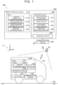
- FIG. 1 illustrates a schematic configuration of a remote control system 500 including a remote control device 300 according to a first embodiment of the present disclosure.
- the remote control device 300 generates a control command for autonomous driving of a vehicle 100 by remote control, and transmits it to the vehicle 100.
- the remote control system 500 is used, for example, in a factory that manufactures the vehicle 100 that can travel by remote control.
- Examples of the vehicle 100 include a passenger car, a truck, a bus, and a construction vehicle.
- the vehicle 100 is preferably a battery electric vehicle (BEV).
- BEV battery electric vehicle
- the vehicle 100 is not limited to the battery electric vehicle, and may be, for example, a gasoline vehicle, a hybrid electric vehicle, or a fuel cell electric vehicle.
- the vehicle 100 includes a vehicle communication device 190, actuators 140, and an electronic control unit (ECU) 200.
- ECU electronice control unit
- the ECU 200 is mounted on the vehicle 100 and executes various types of control in the vehicle 100.
- the ECU 200 includes a storage device 220 such as a hard disk drive (HDD), a solid state drive (SSD), an optical recording medium, or a semiconductor memory, a central processing unit (CPU) 210, and an interface circuit 230.
- the CPU 210, the storage device 220, and the interface circuit 230 are connected via an internal bus so that they can communicate bidirectionally.
- the actuators 140 and the vehicle communication device 190 are connected to the interface circuit 230.
- the vehicle communication device 190 performs wireless communication with devices outside the vehicle 100 connected to the network, such as the remote control device 300, via an access point in the factory, etc.
- a read/write area of the storage device 220 stores a computer program for implementing at least part of the functions provided in the present embodiment.
- the functions such as a driving control unit 212 are implemented by the CPU 210 executing various computer programs stored in the memory.
- the driving control unit 212 executes driving control on the vehicle 100.
- the “driving control” refers to various types of control for driving the actuators 140 that execute functions of "running", “turning”, and “stopping” of the vehicle 100, as typified by adjustment of an acceleration, a speed, and a steering angle.
- the actuators 140 include an actuator of a drive device for accelerating the vehicle 100, an actuator of a steering device for changing the traveling direction of the vehicle 100, and an actuator of a braking device for decelerating the vehicle 100.
- the drive device includes a battery, a traveling motor to be driven by battery power, and drive wheels to be rotated by the traveling motor.
- the actuator of the drive device includes the traveling motor.
- the actuators 140 may further include an actuator for swinging a wiper of the vehicle 100, an actuator for opening and closing a power window of the vehicle 100, etc.
- the driving control unit 212 can cause the vehicle 100 to travel by controlling the actuators 140 in response to the driver's operations.
- the driving control unit 212 can also cause the vehicle 100 to travel by controlling the actuators 140 in response to a control command transmitted from the remote control device 300 regardless of whether a driver is in the vehicle 100.
- the remote control system 500 includes one or more vehicle detectors 80 together with the remote control device 300.
- the vehicle detector 80 is a device for measuring various types of data to be used to estimate at least one of the position of the vehicle 100 and the orientation of the vehicle 100.
- the vehicle detector 80 is a light detection and ranging (LiDAR) sensor that is a distance measuring device that measures three-dimensional point cloud data of the vehicle 100.
- the three-dimensional point cloud data indicates the three-dimensional position of a point cloud. With the LiDAR sensor, highly accurate three-dimensional point cloud data can be acquired.
- the orientation and the traveling direction of the vehicle 100 may be estimated by acquiring only the position of the vehicle 100 using the vehicle detector 80 and acquiring changes in the vehicle 100 over time.
- the vehicle detector 80 is connected to the remote control device 300 to communicate with the remote control device 300 by wireless or by wire.
- the remote control device 300 can acquire the position and orientation of the vehicle 100 relative to a target route RT in real time.
- the position of the vehicle detector 80 is fixed near a traveling road SR, and the relative relationship between a reference coordinate system ⁇ r and a device coordinate system of the vehicle detector 80 is known.
- a coordinate transformation matrix for mutually transforming coordinate values of the reference coordinate system ⁇ r and coordinate values of the device coordinate system of the vehicle detector 80 is prestored in the remote control device 300.
- the remote control device 300 executes driving control on the vehicle 100 by remote control.
- the remote control device 300 transports the vehicle 100 during a manufacturing process in the factory by, for example, autonomous driving of the vehicle 100 by remote control.
- the transportation of the vehicle 100 using autonomous driving by remote control is also referred to as "autonomous driving transportation".
- the autonomous driving transportation allows the vehicle 100 to move without using a transport device such as a crane or a conveyor.
- the remote control device 300 may monitor the surroundings of the vehicle 100.
- the remote control device 300 includes a central processing unit (CPU) 310, a storage device 340, an interface circuit 350, and a remote communication device 390.
- the CPU 310, the storage device 340, and the interface circuit 350 are connected via an internal bus so that they can communicate bidirectionally.
- the remote communication device 390 is connected to the interface circuit 350.
- the remote communication device 390 communicates with the vehicle 100 via a network etc.
- the storage device 340 is, for example, a random access memory (RAM), a read only memory (ROM), an HDD, or an SSD.
- a read/write area of the storage device 340 stores vehicle point cloud data VP, the target route RT, an actuator drive history AC, and a previous matching position BM.
- the target route RT is a predetermined traveling route for the vehicle 100 on the traveling road SR.
- the vehicle point cloud data VP functions as a template point cloud for estimating at least one of the position and orientation of the vehicle 100.
- three-dimensional computer-aided design (CAD) data of the vehicle 100 can be used as the vehicle point cloud data VP.
- the vehicle point cloud data VP may include information for determining the orientation of the vehicle 100.
- template matching using the vehicle point cloud data VP the position and orientation of the vehicle 100 in the three-dimensional point cloud data can be estimated with high accuracy.
- the actuator drive history AC is a history of input and output values for each actuator 140 of the vehicle 100.
- the actuator drive history AC may be, for example, a history of control command values transmitted from the remote control device 300 to the vehicle 100 or actual measurement values acquired from detectors of the vehicle 100, such as a vehicle speed, a steering angle, a braking force, and a rotation angle.
- the previous matching position BM is a coordinate value of a position where previous template matching between the three-dimensional point cloud data and the vehicle point cloud data VP by a position estimation unit 318 has been completed.
- the storage device 340 stores a computer program for implementing at least part of the functions provided in the present embodiment.
- the CPU 310 executes the computer program stored in the storage device 340 to function as a remote control unit 312, a point cloud data acquisition unit 314, a start position determination unit 316, and the position estimation unit 318. Part or all of these functions may be implemented by hardware circuits.
- the point cloud data acquisition unit 314 acquires three-dimensional point cloud data measured by the vehicle detector 80.
- the start position determination unit 316 determines a start position to start matching the vehicle point cloud data VP with the acquired three-dimensional point cloud data.
- the start position to start matching is preferably the position of the vehicle 100 to be detected in the three-dimensional point cloud data or a position near the position of the vehicle 100 from the viewpoint of completing template matching quickly.
- the start position determination unit 316 determines the start position of template matching using information on the position of the vehicle 100 in the three-dimensional point cloud data.
- the "information on the position of the vehicle 100 in the three-dimensional point cloud data” is data to be used to estimate the position of the vehicle 100 in the three-dimensional point cloud data or a position near the position of the vehicle 100.
- the "information on the position of the vehicle 100 in the three-dimensional point cloud data” is acquired by a method different from template matching, and is used in a process before template matching is executed.
- the "information on the position of the vehicle 100 in the three-dimensional point cloud data” is preferably small-size data, data obtained through simple processing, etc. to increase the processing speed of template matching.
- the position estimation unit 318 estimates the position and orientation of the vehicle 100 in the acquired three-dimensional point cloud data.
- the position estimation unit 318 estimates the position and orientation of the vehicle 100 in the three-dimensional point cloud data by executing template matching using the vehicle point cloud data VP on the three-dimensional point cloud data.
- an iterative closest point (ICP) algorithm or a normal distribution transform (NDT) algorithm can be used for template matching of the vehicle point cloud data VP with the three-dimensional point cloud data.
- the remote control unit 312 generates a control command for remote control using the estimated position and orientation of the vehicle 100, and transmits it to the vehicle 100.
- the control command is a command to cause the vehicle 100 to travel along the target route RT stored in the storage device 340.
- the control command can be generated as a command including a driving force or a braking force and a steering angle. Alternatively, the control command may be generated as a command including at least one of the position and orientation of the vehicle 100 and a future traveling route.
- driving control is implemented by the driving control unit 212 of the ECU 200, and as a result, the vehicle 100 automatically travels.
- FIG. 2 schematically illustrates a traveling method for the vehicle 100.
- FIG. 2 shows how the autonomous driving transportation of the vehicle 100 is executed in a factory FC that manufactures the vehicle 100.
- the factory FC includes a first process 50 and a second process 60.
- the first process 50 is, for example, a place where the vehicle 100 is assembled
- the second process 60 is, for example, a place where the vehicle 100 is inspected.
- the first process 50 and the second process 60 are connected by the traveling road SR where the vehicle 100 can travel. Any position in the factory FC is represented by xyz coordinate values of the reference coordinate system ⁇ r.
- the remote control device 300 causes the vehicle 100 to travel along the target route RT while estimating, at predetermined time intervals, the position and orientation of the vehicle 100 in the three-dimensional point cloud data acquired by the vehicle detector 80.
- the target route RT set on the traveling road SR includes mutually continuous target routes RT1, RT2, RT3.
- the remote control device 300 switches the vehicle detectors 80 as appropriate based on the position of the vehicle 100, estimates the position and orientation of the vehicle 100, and causes the vehicle 100 to travel along the target route RT.
- the vehicle 100 that has departed from the first process 50 travels along the target route RT1 by remote control using the three-dimensional point cloud data acquired by the vehicle detector 80A.
- the vehicle detector 80A is switched to the vehicle detector 80B suitable for detecting the vehicle 100 traveling on the target route RT2.
- the vehicle detector 80B is similarly switched to the vehicle detector 80C suitable for detecting the vehicle 100.
- FIG. 3 is a flowchart showing a processing routine of a traveling process for the vehicle 100 by remote control according to the present embodiment. This flow starts when the vehicle 100 starts traveling on the traveling road SR. This flow may be repeated every time the point cloud data acquisition unit 314 newly acquires three-dimensional point cloud data from the vehicle detector 80 that executes measurement for the vehicle 100 to be controlled.
- step S100 the point cloud data acquisition unit 314 acquires three-dimensional point cloud data from the vehicle detector 80.
- step S200 the start position determination unit 316 executes a start position determination process.
- the "start position determination process” is a process for determining a start position to start matching of the vehicle point cloud data VP with the acquired three-dimensional point cloud data.
- step S300 template matching is started from the start position determined by the start position determination process.
- matching is sequentially executed around the start position. Template matching is repeated while changing the matching position until completion.
- the position estimation unit 318 estimates the position and orientation of the vehicle 100 in the three-dimensional point cloud data by executing template matching using the vehicle point cloud data VP.
- the remote control unit 312 generates a control command for causing the vehicle 100 to travel along the target route RT using the estimated position and orientation of the vehicle 100, and transmits it to the vehicle 100.
- FIG. 4 is a flowchart showing an example of a processing routine of the start position determination process according to the first embodiment.
- the previous matching position BM where previous matching between the three-dimensional point cloud data and the vehicle point cloud data VP has been completed or the target route RT of the vehicle 100 is selectively used as the "information on the position of the vehicle 100 in the three-dimensional point cloud data" depending on whether a previous matching result is present.
- step S210 the start position determination unit 316 checks whether a matching result of previous template matching is present. Whether a previous matching result is present can be checked based on, for example, whether the previous matching result is stored in a processing history stored in the storage device 340 or whether the previous matching position BM is stored in the storage device 340.
- the start position determination unit 316 advances the process to step S250.
- the target route RT of the vehicle 100 is used as the "information on the position of the vehicle 100 in the three-dimensional point cloud data".
- the start position determination unit 316 acquires the target route RT stored in the storage device 340.
- step S260 the traveling start position of the vehicle 100 on the target route RT is acquired.
- the traveling start position of the vehicle 100 on the target route RT is, for example, prestored in the storage device 340 in association with the target route RT.
- the traveling start position of the vehicle 100 is near the exit of the first process 50.
- step S270 the start position determination unit 316 determines the start position of template matching to be the acquired traveling start position on the target route RT, and terminates this flow.
- the processing period of template matching can be reduced by setting the traveling start position of the vehicle 100 on the target route RT as the start position.
- step S210 When a previous matching result is present in step S210 (S210: YES), the start position determination unit 316 advances the process to step S220.
- the previous matching position BM where previous matching between the three-dimensional point cloud data and the vehicle point cloud data VP has been completed is used as the "information on the position of the vehicle 100 in the three-dimensional point cloud data".
- the position of the vehicle 100 after traveling at the time of executing current matching is further estimated using the previous matching position BM, and the position after traveling is used as the "information on the position of the vehicle 100 in the three-dimensional point cloud data".
- the start position determination unit 316 acquires the actuator drive history AC of the vehicle 100.
- the acquired actuator drive history AC includes at least a drive history of the actuators 140 about the traveling of the vehicle 100 during a period from the time of completion of the previous matching to the time before execution of the current matching.
- the start position determination unit 316 estimates the position of the vehicle 100 after traveling during the period from the time of completion of the previous matching to the time before execution of the current matching. Specifically, the start position determination unit 316 estimates the position of the vehicle 100 after traveling by estimating a traveling route from the previous matching position BM using the drive history of the actuators 140.
- the start position determination unit 316 determines the estimated position of the vehicle 100 after traveling as the start position of template matching, and terminates this flow.
- FIG. 5 illustrates the estimated position of the vehicle 100 after traveling from the previous matching position.
- FIG. 5 shows an example of three-dimensional point cloud data PD1 acquired from the vehicle detector 80.
- the three-dimensional point cloud data PD1 schematically shows a position BM1 of the vehicle 100 at the time of previous matching as an example of the previous matching position BM, and a position AM of the vehicle 100 after traveling on a traveling route AR from the previous matching position.
- the position AM of the vehicle 100 after traveling can be acquired, for example, by estimating the traveling route AR or the position AM of the vehicle 100 obtained from the actuator drive history AC, starting from the position BM1 at the time of previous matching.
- the start position determination unit 316 may estimate the traveling route AR or the position AM of the vehicle 100 based on output values from the detectors that acquire a vehicle speed, a steering angle, a braking force, a rotation angle, etc., instead of the actuator drive history AC.
- the current position of the vehicle 100 acquired from a global navigation satellite system (GNSS) receiver etc. may be used as the position AM of the vehicle 100 after traveling.
- GNSS global navigation satellite system
- the start position determination unit 316 determines the estimated position AM of the vehicle 100 after traveling as the start position of template matching, and the position estimation unit 318 starts template matching using the vehicle point cloud data VP from the position AM.
- the position AM of the vehicle 100 By setting the position AM of the vehicle 100 after traveling as the start position of template matching, the actual position of the vehicle 100 or its vicinity can be set as the start position. Therefore, the processing period required for template matching can be shortened. Compared to a case where template matching is started at a position far from the position AM, it is possible to reduce such trouble that the matching is completed at a position different from the actual position of the vehicle 100 due to a local solution obtained by gradient descent etc. Thus, the accuracy of detection of the vehicle 100 can be improved.
- the remote control device 300 of the present embodiment includes the point cloud data acquisition unit 314 configured to acquire three-dimensional point cloud data measured using the vehicle detector 80, the position estimation unit 318 configured to estimate the position and orientation of the vehicle 100 in the three-dimensional point cloud data by matching the vehicle point cloud data VP with the three-dimensional point cloud data, the start position determination unit 316 configured to determine a start position to start template matching for the three-dimensional point cloud data by the position estimation unit 318, and the remote control unit 312 configured to generate a control command for remotely controlling the vehicle 100 using the estimated position and orientation of the vehicle 100 and transmit the control command to the vehicle 100.
- the remote control device 300 of the present embodiment can quickly detect the position of the vehicle 100 by setting the start position of matching near the vehicle 100. Therefore, the processing period required for template matching can be shortened.
- the start position determination unit 316 determines the start position using information on the position of the vehicle 100 in the three-dimensional point cloud data acquired by the point cloud data acquisition unit 314.
- the position of the vehicle 100 can quickly be detected by setting the start position of template matching to the position of the vehicle 100 using the information on the position of the vehicle 100. Therefore, the processing period required for template matching can be shortened.
- the start position determination unit 316 acquires the previous matching position BM, and determines the start position of template matching using the acquired previous matching position BM.
- the processing period required for template matching can be shortened through simple processing.
- the start position determination unit 316 estimates the position AM of the vehicle 100 after traveling from the previous matching position BM during a period from the time of completion of the previous matching to the time before execution of the current matching, and determines the estimated position AM after traveling as the start position of template matching.
- the start position of matching can be set closer to the position of the vehicle 100 at the time of current matching. Therefore, the processing period required for template matching can further be shortened.
- the start position determination unit 316 determines the traveling start position on the target route RT as the start position of template matching.
- the traveling start position where the vehicle 100 is highly likely to be present is set as the start position. Therefore, the processing period required for template matching can further be shortened.
- FIG. 6 is a block diagram showing the internal functional configuration of a remote control device 300b according to a second embodiment.
- the remote control device 300b of the present embodiment differs from the remote control device 300 of the first embodiment in that a CPU 310b that further functions as an object detection unit 322 is provided instead of the CPU 310, and that a storage device 340b that further stores vehicle identification information VI and a trained model LM is provided instead of the storage device 340.
- the other configuration is the same.
- the trained model LM is a machine learning model that executes object detection by a predetermined object detection method using deep learning.
- the trained model LM has sufficiently been trained using a predetermined data set.
- various methods using a convolutional neural network (CNN) can be used for the trained model LM.
- CNN convolutional neural network
- object detection it is particularly preferable to employ a method using deep learning such as region-convolutional neural networks (R-CNN), Fast R-CNN, Faster R-CNN, versions of You Only Look Once (YOLO), or single shot detector (SSD).
- R-CNN region-convolutional neural networks
- YOLO You Only Look Once
- SSD single shot detector
- the object detection unit 322 executes annotation on three-dimensional point cloud data using the trained model LM, and detects the provisional position of the vehicle in the three-dimensional point cloud data.
- vehicle in this case means a vehicle as an attribute (class), and may include vehicles other than the vehicle 100 to be controlled.
- the object detection unit 322 executes object detection by inputting the detected three-dimensional point cloud data to the trained model LM, and generates a 3D bounding box for a region recognized as a vehicle.
- the "bounding box” means a partial region extracted from an external region of three-dimensional point cloud data by enclosing an object region of a vehicle with the smallest rectangular box. That is, the object detection unit 322 extracts the region occupied by the vehicle in the three-dimensional point cloud data by forming the bounding box.
- the vehicle identification information VI means various types of information that can identify each vehicle 100.
- the vehicle identification information VI includes, for example, identification (ID) information assigned to each vehicle 100, such as a vehicle identification number (VIN), specification information of the vehicle 100, such as a vehicle type, a color, a shape, and a size, and production management information of the vehicle 100, such as the name of a process in progress.
- the vehicle identification information VI may include the size of a bounding box that can be detected.
- the vehicle identification information VI can be acquired, for example, from a radio frequency-identification (RF-ID) tag attached to the vehicle 100 by short-range wireless communication.
- RFID radio frequency-identification
- FIG. 7 is a flowchart showing a start position determination process according to the second embodiment.
- the object detection unit 322 executes object detection using acquired three-dimensional point cloud data, and acquires the provisional position of the vehicle 100 in the three-dimensional point cloud data. More specifically, the object detection unit 322 generates bounding boxes for vehicles in the acquired three-dimensional point cloud data by inputting the three-dimensional point cloud data to the trained model LM.
- step S610 the object detection unit 322 acquires the vehicle identification information VI of the vehicle 100 to be controlled.
- step S620 the object detection unit 322 extracts a bounding box associated with the vehicle 100 to be controlled using the vehicle identification information VI.
- the object detection unit 322 extracts, from the generated bounding boxes, a bounding box that matches the size of the bounding box associated with the vehicle identification information VI of the vehicle 100 to be controlled or the size of the vehicle 100.
- the vehicle identification information VI may indicate the shape of part or whole of the vehicle 100 or the length, width, and height of part or whole of the vehicle 100.
- the start position determination unit 316 determines the position of the extracted bounding box as the start position of template matching, and terminates this flow.
- FIG. 8 illustrates template matching in the start position determination process according to the second embodiment.
- FIG. 8 shows an example of three-dimensional point cloud data PD2 acquired from the vehicle detector 80.
- the three-dimensional point cloud data PD2 includes three-dimensional point cloud data of the vehicle 100 to be controlled, and three-dimensional point cloud data of a vehicle 100R that is not to be controlled.
- the object detection unit 322 generates bounding boxes BB 1, BB2 for the vehicle 100 and the vehicle 100R recognized as vehicles by inputting the three-dimensional point cloud data PD2 into the trained model LM.
- the object detection unit 322 acquires the vehicle identification information VI.
- the vehicle identification information VI in this case is preferably information on, for example, the sizes and widths of the vehicles 100, 100R or the sizes of the bounding boxes as information convenient for distinguishing the vehicles 100, 100R having different sizes.
- the bounding box BB1 of the vehicle 100 is extracted out of the bounding boxes BB1, BB2.
- the start position determination unit 316 determines the position of the extracted bounding box BB1 as the start position of template matching, and the position estimation unit 318 starts template matching using the vehicle point cloud data VP from the position of the bounding box BB1 as the start position.
- the start position determination unit 316 determines, as the start position, the position of the vehicle 100 detected from the three-dimensional point cloud data PD2 by the predetermined object detection method using deep learning.
- the position of the vehicle 100 can be extracted from the three-dimensional point cloud data PD2 using the known method that is the object detection using deep learning.
- the start position can be set near the vehicle 100 using the position of the vehicle 100 in the three-dimensional point cloud data PD2. Therefore, the processing period required for template matching can be shortened.
- the start position determination unit 316 when the positions of the plurality of vehicles 100, 100R are detected, the start position determination unit 316 further uses the vehicle identification information VI for identifying the vehicle 100 to determine the start position using the position of the vehicle 100 associated with the vehicle identification information VI out of the detected positions of the plurality of vehicles 100. Therefore, the position of the vehicle 100 to be controlled can be extracted even when the plurality of vehicles 100, 100R is detected by the object detection method using deep learning.
- FIG. 9 is a top view illustrating an example of the overall configuration of a remote control device 300c according to a third embodiment.
- the remote control device 300c of the present embodiment is an automated guided vehicle also called "guide mobility".
- the remote control device 300c has a function of autonomously driving the vehicle 100 by remote control as in the first embodiment, and also has a function of autonomously driving the body of the remote control device 300c on the traveling road SR. That is, the remote control device 300c autonomously drives the succeeding vehicle 100 by remote control to guide it while being autonomously driven on the traveling road SR.
- the remote control device 300c includes drive wheels 142 for autonomous driving, an autonomous driving detector 70, and a vehicle detector 80.
- the function of the vehicle detector 80 is the same as that of the vehicle detector 80 shown in the first embodiment, and therefore description thereof will be omitted.
- the autonomous driving detector 70 is a distance measuring device such as a camera or a LiDAR sensor. Data acquired by the autonomous driving detector 70 is used for simultaneous localization and mapping (SLAM) for autonomous driving of the remote control device 300c.
- the camera may be a stereo camera, a monocular camera, an RGB-D camera (depth camera), etc.
- a time-of-flight (ToF) sensor etc. may be used instead of the camera or the LiDAR sensor.
- the vehicle detector 80 is only mounted on the remote control device 300c.
- the vehicle detector 80 may also be installed around the traveling road SR.
- FIG. 10 is a block diagram showing the internal functional configuration of the remote control device 300c according to the third embodiment.
- the internal functional configuration of the remote control device 300c differs from that of the remote control device 300 of the first embodiment in that a CPU 310c that further functions as a SLAM unit 328 and an autonomous driving control unit 330 is provided instead of the CPU 310, and that a storage device 340c that further stores a guide vehicle route GR is provided instead of the storage device 340.
- the other configuration is the same.
- the guide vehicle route GR is a predetermined target route where the remote control device 300c is expected to travel.
- Actuators 360 include actuators of a drive device, a steering device, and a braking device for autonomous driving of the remote control device 300c.
- the drive device includes a battery, a traveling motor to be driven by battery power, and the drive wheels 142 to be rotated by the traveling motor.
- the SLAM unit 328 executes SLAM using data detected by the autonomous driving detector 70, and generates a map for autonomous driving of the remote control device 300c.
- the autonomous driving control unit 330 controls the actuators 360 to autonomously drive the remote control device 300c. Specifically, the autonomous driving control unit 330 autonomously drives the remote control device 300c along the guide vehicle route GR stored in the storage device 340c using the map generated by the SLAM unit 328.
- the remote control device 300c when the remote control device 300c travels along the guide vehicle route GR, the vehicle 100 is guided by the remote control of the remote control device 300c and travels on the same traveling route as that of the remote control device 300c.
- template matching is executed on the three-dimensional point cloud data acquired from the vehicle detector 80, and the start position determination unit 316 executes the start position determination process for determining the start position of template matching.
- the remote control device 300c that is autonomously driven also sets the start position of template matching near the vehicle 100 using the information on the position of the vehicle 100. Therefore, the processing period required for template matching can be shortened.
- the second embodiment illustrates the example in which the bounding box of the vehicle is generated by the object detection method using deep learning and the position of the vehicle 100 extracted using the generated bounding box is determined as the start position.
- the object detection unit 322 may execute preprocessing to remove background point cloud data representing stationary objects from the acquired three-dimensional point cloud data. This preprocessing is also called "background subtraction".
- the start position determination unit 316 determines, as the start position of template matching, the provisional position of the vehicle 100 detected based on a difference between the point cloud data associated with the background of the three-dimensional point cloud data and the point cloud data associated with the vehicle 100 to be detected.
- the remote control device 300 configured in this way can determine the start position through the simple processing that is the background subtraction.
- the first embodiment illustrates the example in which the start position determination unit 316 sets the traveling start position of the vehicle 100 on the target route RT as the start position when no previous matching result is present.
- the start position determination unit 316 may set the traveling start position of the vehicle 100 on the target route RT as the start position regardless of whether the previous matching result is present. Instead of the traveling start position on the target route RT, any position on the target route RT may be determined as the start position. In this case, step S260 shown in FIG. 4 can be omitted.
- the remote control device 300 configured in this way, the processing period required for template matching can be shortened by setting the start position on the target route RT where the vehicle 100 is highly likely to be present.
- template matching is preferably executed along the target route RT.
- the start position determination unit 316 may acquire the previous matching position BM on the target route RT last time, and determine the start position using the acquired previous matching position BM on the target route RT. With the remote control device 300 configured in this way, the processing period required for template matching can be shortened by the simple method using the previous matching position BM on the target route RT where the vehicle 100 is more highly likely to be present.
- the vehicle 100 is a passenger car, a truck, a bus, a construction vehicle, etc.
- the vehicle 100 is not limited to these, and may include various automobiles such as two-wheeled vehicles and four-wheeled vehicles, trains, etc.
- Various moving objects other than the vehicle 100 may be used.
- the "moving object” means an object that can move. Examples of the moving object include an electric vertical take-off and landing aircraft (so-called flying car), a ship, an aircraft, a robot, and a magnetically levitated train.
- flying car electric vertical take-off and landing aircraft
- the terms "vehicle” and “car” in the present disclosure can be replaced with “moving object” as appropriate, and the term “travel” can be replaced with "move” as appropriate.
- the vehicle 100 only needs to have a configuration in which the vehicle 100 can move by remote control.
- the vehicle 100 may be in the form of a platform having a configuration described below.
- the vehicle 100 only needs to have a configuration to execute the functions of "running", "turning", and "stopping" by remote control. That is, the "vehicle 100 that can move by remote control” need not have at least part of the interior components such as a driver's seat and a dashboard, at least part of the exterior components such as a bumper and a fender, or a body shell.
- the remaining components such as the body shell may be mounted on the vehicle 100 before the vehicle 100 is shipped from the factory, or may be mounted on the vehicle 100 after the vehicle 100 is shipped from the factory with the remaining components such as the body shell unmounted on the vehicle 100.
- the first embodiment illustrates the example in which the start position determination unit 316 further estimates the position AM of the vehicle 100 after traveling from the previous matching position BM.
- the start position may be a position other than the position AM after traveling.
- the previous matching position BM may be used.
- the first embodiment illustrates the example in which the start position determination unit 316 determines the start position using the previous matching position BM, and the example in which the start position determination unit 316 determines any position on the target route RT as the start position.
- the start position determination unit 316 may determine a position other than the previous matching position BM or a position different from the target route RT as the start position.
- the start position determination unit 316 may determine, as the start position, the provisional position of the vehicle 100 acquired based on a detection result from a detector different from the vehicle detector 80.
- the third embodiment illustrates the example in which the object detection unit 322 extracts the vehicle 100 to be controlled using the vehicle identification information VI.
- the vehicle identification information VI need not be used.
- the object detection unit 322 need not acquire the vehicle identification information VI. In this case, steps S610, S620 shown in FIG. 7 may be omitted.
- the controls and their methods described in the present disclosure may be implemented by a dedicated computer provided by configuring a memory and a processor programmed to execute one or more functions implemented by a computer program.
- the controls and their methods described in the present disclosure may be implemented by a dedicated computer provided by configuring a processor with one or more dedicated hardware logic circuits.
- the controls and their methods described in the present disclosure may be implemented by one or more dedicated computers configured by a combination of a memory and a processor programmed to execute one or more functions and a processor configured by one or more hardware logic circuits.
- the computer program may be stored in a computer-readable non-transitory tangible storage medium as instructions to be executed by a computer.
Landscapes
- Engineering & Computer Science (AREA)
- Physics & Mathematics (AREA)
- General Physics & Mathematics (AREA)
- Automation & Control Theory (AREA)
- Aviation & Aerospace Engineering (AREA)
- Radar, Positioning & Navigation (AREA)
- Remote Sensing (AREA)
- Control Of Position, Course, Altitude, Or Attitude Of Moving Bodies (AREA)
Abstract
A remote control device (300) includes, at least one processer configured to perform processes including, acquiring three-dimensional point cloud data measured using a distance measuring device (80), estimating at least one of a position and an orientation of a moving object (100) in the three-dimensional point cloud data by matching a template point cloud indicating the moving object (100) with the three-dimensional point cloud data, determining a start position to start matching of the template point cloud with the three-dimensional point cloud data; and generating a control command for remotely controlling the moving object (100) using at least one of the estimated position and the estimated orientation of the moving object (100) and transmit the control command to the moving object (100).
Description
- The present disclosure relates to a remote control device.
- There is known a technology for detecting the position of an object in a space. For example,
Japanese Unexamined Patent Application Publication No. 11-259658 JP 11-259658 A - In the related art, the scanning is sequentially executed after the two-dimensional model stored in the memory is positioned at the leading point of the two-dimensional projected images. Therefore, there is a problem that a long period of time is required to complete the matching. Therefore, in the technology for detecting the position of a moving obj ect by matching a model stored in a memory, there is a demand for a technology for shortening the period of time required to detect the position of the moving object.
- The present disclosure can be realized in the following aspects.
- A remote control device includes, at least one processer configured to perform processes including, acquiring three-dimensional point cloud data measured using a distance measuring device, estimating at least one of a position and an orientation of a moving object in the three-dimensional point cloud data by matching a template point cloud indicating the moving object with the three-dimensional point cloud data, determining a start position to start matching of the template point cloud with the three-dimensional point cloud data, and generating a control command for remotely controlling the moving object using at least one of the estimated position and the estimated orientation of the moving object and transmit the control command to the moving object.
The remote control device of this aspect can quickly detect the position of the moving object by determining the start position of matching near the moving object. Therefore, the processing period required to detect the position of the moving object by template matching can be shortened.
In the remote control device of the above aspect, the processes may further include determining the start position using information on a drive history of an actuator provided in the moving object, out of information on a position used for the matching and information included in the control command, and using information on at least one of the position and the orientation of the moving object used to generate the control command, and of a target route predetermined as a traveling route of the moving object by the remotely controlling. In the remote control device of the above aspect, the processes may further include determining the start position using actuator drive history which is at least one of: a history of control command values transmitted from the remote control device to the vehicle; actual measurement values acquired from detectors of the vehicle; and a previous matching position, or a target route of the vehicle. - In the remote control device of the above aspect, the processes may further include determining the start position using an information on the position of the moving object in the three-dimensional point cloud data.
The remote control device of this aspect can quickly detect the position of the moving object by determining the start position of template matching using the information on the position of the moving object. Therefore, the processing period required for template matching can be shortened. - In the remote control device of the above aspect, the processes may further include, acquiring as the information on the position of the moving object, a previous matching position where previous matching between the three-dimensional point cloud data and the template point cloud has been completed, and determining the start position using the acquired previous matching position.
With the remote control device of this aspect, the processing period required for template matching can be shortened through simple processing using the previous matching position that is highly likely to be near the position of the moving object at the time of current matching. - In the remote control device of the above aspect, the processes may further include, estimating a position of the moving object after movement from the previous matching position during a period from a time of completion of the previous matching to a time before execution of current matching; and determining the start position using the estimated position after the movement.
The remote control device of this aspect can set the start position of matching closer to the position of the moving object at the time of current matching by estimating the position of the moving object after the movement. Therefore, the processing period required for template matching can further be shortened. - The remote control device of the above aspect, may further include a storage device configured to store a target route of the moving object that is the information on the position of the moving object, and the processes may further include determine any position on the target route as the start position.
The remote control device of this aspect can quickly detect the position of the moving object by setting the start position on the target route where the moving object is highly likely to be present. Therefore, the processing period required for template matching can be shortened. - In the remote control device of the above aspect, the processes may further include, acquiring a previous matching position where previous matching between the three-dimensional point cloud data and the template point cloud has been completed on the target route, and determining the start position using the acquired previous matching position on the target route.
The remote control device of this aspect can more quickly detect the position of the moving object using the previous matching position on the target route where the moving object is more highly likely to be present. - In the remote control device of the above aspect, the processes may further include determining the start position using, as the information on the position of the moving object, a position of the moving object detected from the three-dimensional point cloud data by a predetermined object detection method, or a position of the moving object detected based on a difference between point cloud data associated with a background of the three-dimensional point cloud data and point cloud data associated with the moving object.
The remote control device of this aspect can extract the provisional position of the moving object using the object detection, and quickly detect the position of the moving object by the simple method. Therefore, the processing period required for template matching can be shortened. - In the remote control device of the above aspect, the processes may further include determining the start position using the position of the moving object associated with a moving object identification information, for identifying the moving object, out of the detected positions of the moving objects, when a plurality of positions of the moving objects is detected.
The remote control device of this aspect can extract the position of the moving object to be controlled using the moving object identification information even when the plurality of provisional positions of the moving objects is detected by the object detection. - In the remote control device of the above aspect, the distance measuring device may be configured to communicate with the at least one processor, and the distance measuring device may be configured to transmit the three-dimensional point cloud data to the remote control device.
- In the remote control device of the above aspect, the distance measuring device may be installed on around a traveling road of the moving object.
- The remote control device of the above aspect, may further include the distance measuring device.
- The present disclosure can also be implemented in various forms other than the remote control device. For example, the present disclosure can be implemented in the form of a remote control system, a method for moving a moving object, a method for manufacturing the moving obj ect, a method for detecting the moving obj ect, a moving obj ect detection device, a method for controlling the remote control system, a method for controlling the remote control device, a computer program that implements these control methods, or a non-transitory recording medium that records the computer program.
- Features, advantages, and technical and industrial significance of exemplary embodiments of the invention will be described below with reference to the accompanying drawings, in which like signs denote like elements, and wherein:
-
FIG. 1 illustrates a schematic configuration of a remote control system; -
FIG. 2 schematically illustrates a vehicle traveling method; -
FIG. 3 is a flowchart showing a processing routine of a vehicle traveling process by remote control; -
FIG. 4 is a flowchart showing a processing routine of a start position determination process according to a first embodiment; -
FIG. 5 illustrates an estimated position of a vehicle after traveling from a previous matching position; -
FIG. 6 is a block diagram showing the internal functional configuration of a remote control device according to a second embodiment; -
FIG. 7 is a flowchart showing a start position determination process according to the second embodiment; -
FIG. 8 illustrates template matching in the start position determination process according to the second embodiment; -
FIG. 9 is a top view illustrating an example of the overall configuration of a remote control device according to a third embodiment; and -
FIG. 10 is a block diagram showing the internal functional configuration of the remote control device according to the third embodiment. -
FIG. 1 illustrates a schematic configuration of aremote control system 500 including aremote control device 300 according to a first embodiment of the present disclosure. Theremote control device 300 generates a control command for autonomous driving of avehicle 100 by remote control, and transmits it to thevehicle 100. Theremote control system 500 is used, for example, in a factory that manufactures thevehicle 100 that can travel by remote control. - Examples of the
vehicle 100 include a passenger car, a truck, a bus, and a construction vehicle. Thevehicle 100 is preferably a battery electric vehicle (BEV). Thevehicle 100 is not limited to the battery electric vehicle, and may be, for example, a gasoline vehicle, a hybrid electric vehicle, or a fuel cell electric vehicle. Thevehicle 100 includes avehicle communication device 190,actuators 140, and an electronic control unit (ECU) 200. - The
ECU 200 is mounted on thevehicle 100 and executes various types of control in thevehicle 100. TheECU 200 includes astorage device 220 such as a hard disk drive (HDD), a solid state drive (SSD), an optical recording medium, or a semiconductor memory, a central processing unit (CPU) 210, and an interface circuit 230. TheCPU 210, thestorage device 220, and the interface circuit 230 are connected via an internal bus so that they can communicate bidirectionally. Theactuators 140 and thevehicle communication device 190 are connected to the interface circuit 230. Thevehicle communication device 190 performs wireless communication with devices outside thevehicle 100 connected to the network, such as theremote control device 300, via an access point in the factory, etc. - A read/write area of the
storage device 220 stores a computer program for implementing at least part of the functions provided in the present embodiment. The functions such as a drivingcontrol unit 212 are implemented by theCPU 210 executing various computer programs stored in the memory. - The driving
control unit 212 executes driving control on thevehicle 100. The "driving control" refers to various types of control for driving theactuators 140 that execute functions of "running", "turning", and "stopping" of thevehicle 100, as typified by adjustment of an acceleration, a speed, and a steering angle. In the present embodiment, theactuators 140 include an actuator of a drive device for accelerating thevehicle 100, an actuator of a steering device for changing the traveling direction of thevehicle 100, and an actuator of a braking device for decelerating thevehicle 100. The drive device includes a battery, a traveling motor to be driven by battery power, and drive wheels to be rotated by the traveling motor. The actuator of the drive device includes the traveling motor. Theactuators 140 may further include an actuator for swinging a wiper of thevehicle 100, an actuator for opening and closing a power window of thevehicle 100, etc. - When a driver is in the
vehicle 100, the drivingcontrol unit 212 can cause thevehicle 100 to travel by controlling theactuators 140 in response to the driver's operations. The drivingcontrol unit 212 can also cause thevehicle 100 to travel by controlling theactuators 140 in response to a control command transmitted from theremote control device 300 regardless of whether a driver is in thevehicle 100. - The
remote control system 500 includes one ormore vehicle detectors 80 together with theremote control device 300. Thevehicle detector 80 is a device for measuring various types of data to be used to estimate at least one of the position of thevehicle 100 and the orientation of thevehicle 100. Thevehicle detector 80 is a light detection and ranging (LiDAR) sensor that is a distance measuring device that measures three-dimensional point cloud data of thevehicle 100. The three-dimensional point cloud data indicates the three-dimensional position of a point cloud. With the LiDAR sensor, highly accurate three-dimensional point cloud data can be acquired. The orientation and the traveling direction of thevehicle 100 may be estimated by acquiring only the position of thevehicle 100 using thevehicle detector 80 and acquiring changes in thevehicle 100 over time. - The
vehicle detector 80 is connected to theremote control device 300 to communicate with theremote control device 300 by wireless or by wire. By acquiring the three-dimensional point cloud data from thevehicle detector 80, theremote control device 300 can acquire the position and orientation of thevehicle 100 relative to a target route RT in real time. In the present embodiment, the position of thevehicle detector 80 is fixed near a traveling road SR, and the relative relationship between a reference coordinate system Σr and a device coordinate system of thevehicle detector 80 is known. A coordinate transformation matrix for mutually transforming coordinate values of the reference coordinate system Σr and coordinate values of the device coordinate system of thevehicle detector 80 is prestored in theremote control device 300. - The
remote control device 300 executes driving control on thevehicle 100 by remote control. Theremote control device 300 transports thevehicle 100 during a manufacturing process in the factory by, for example, autonomous driving of thevehicle 100 by remote control. The transportation of thevehicle 100 using autonomous driving by remote control is also referred to as "autonomous driving transportation". The autonomous driving transportation allows thevehicle 100 to move without using a transport device such as a crane or a conveyor. Theremote control device 300 may monitor the surroundings of thevehicle 100. - The
remote control device 300 includes a central processing unit (CPU) 310, astorage device 340, aninterface circuit 350, and aremote communication device 390. TheCPU 310, thestorage device 340, and theinterface circuit 350 are connected via an internal bus so that they can communicate bidirectionally. Theremote communication device 390 is connected to theinterface circuit 350. Theremote communication device 390 communicates with thevehicle 100 via a network etc. - The
storage device 340 is, for example, a random access memory (RAM), a read only memory (ROM), an HDD, or an SSD. A read/write area of thestorage device 340 stores vehicle point cloud data VP, the target route RT, an actuator drive history AC, and a previous matching position BM. The target route RT is a predetermined traveling route for thevehicle 100 on the traveling road SR. - The vehicle point cloud data VP functions as a template point cloud for estimating at least one of the position and orientation of the
vehicle 100. For example, three-dimensional computer-aided design (CAD) data of thevehicle 100 can be used as the vehicle point cloud data VP. The vehicle point cloud data VP may include information for determining the orientation of thevehicle 100. Through template matching using the vehicle point cloud data VP, the position and orientation of thevehicle 100 in the three-dimensional point cloud data can be estimated with high accuracy. - The actuator drive history AC is a history of input and output values for each
actuator 140 of thevehicle 100. The actuator drive history AC may be, for example, a history of control command values transmitted from theremote control device 300 to thevehicle 100 or actual measurement values acquired from detectors of thevehicle 100, such as a vehicle speed, a steering angle, a braking force, and a rotation angle. As described later, the previous matching position BM is a coordinate value of a position where previous template matching between the three-dimensional point cloud data and the vehicle point cloud data VP by aposition estimation unit 318 has been completed. - The
storage device 340 stores a computer program for implementing at least part of the functions provided in the present embodiment. TheCPU 310 executes the computer program stored in thestorage device 340 to function as aremote control unit 312, a point clouddata acquisition unit 314, a startposition determination unit 316, and theposition estimation unit 318. Part or all of these functions may be implemented by hardware circuits. The point clouddata acquisition unit 314 acquires three-dimensional point cloud data measured by thevehicle detector 80. - The start
position determination unit 316 determines a start position to start matching the vehicle point cloud data VP with the acquired three-dimensional point cloud data. The start position to start matching is preferably the position of thevehicle 100 to be detected in the three-dimensional point cloud data or a position near the position of thevehicle 100 from the viewpoint of completing template matching quickly. - In the present embodiment, the start
position determination unit 316 determines the start position of template matching using information on the position of thevehicle 100 in the three-dimensional point cloud data. The "information on the position of thevehicle 100 in the three-dimensional point cloud data" is data to be used to estimate the position of thevehicle 100 in the three-dimensional point cloud data or a position near the position of thevehicle 100. The "information on the position of thevehicle 100 in the three-dimensional point cloud data" is acquired by a method different from template matching, and is used in a process before template matching is executed. The "information on the position of thevehicle 100 in the three-dimensional point cloud data" is preferably small-size data, data obtained through simple processing, etc. to increase the processing speed of template matching. - The
position estimation unit 318 estimates the position and orientation of thevehicle 100 in the acquired three-dimensional point cloud data. In the present embodiment, theposition estimation unit 318 estimates the position and orientation of thevehicle 100 in the three-dimensional point cloud data by executing template matching using the vehicle point cloud data VP on the three-dimensional point cloud data. For example, an iterative closest point (ICP) algorithm or a normal distribution transform (NDT) algorithm can be used for template matching of the vehicle point cloud data VP with the three-dimensional point cloud data. - The
remote control unit 312 generates a control command for remote control using the estimated position and orientation of thevehicle 100, and transmits it to thevehicle 100. The control command is a command to cause thevehicle 100 to travel along the target route RT stored in thestorage device 340. The control command can be generated as a command including a driving force or a braking force and a steering angle. Alternatively, the control command may be generated as a command including at least one of the position and orientation of thevehicle 100 and a future traveling route. When thevehicle 100 receives a remote control request, driving control is implemented by the drivingcontrol unit 212 of theECU 200, and as a result, thevehicle 100 automatically travels. -
FIG. 2 schematically illustrates a traveling method for thevehicle 100.FIG. 2 shows how the autonomous driving transportation of thevehicle 100 is executed in a factory FC that manufactures thevehicle 100. The factory FC includes afirst process 50 and asecond process 60. Thefirst process 50 is, for example, a place where thevehicle 100 is assembled, and thesecond process 60 is, for example, a place where thevehicle 100 is inspected. Thefirst process 50 and thesecond process 60 are connected by the traveling road SR where thevehicle 100 can travel. Any position in the factory FC is represented by xyz coordinate values of the reference coordinate system Σr. - The
remote control device 300 causes thevehicle 100 to travel along the target route RT while estimating, at predetermined time intervals, the position and orientation of thevehicle 100 in the three-dimensional point cloud data acquired by thevehicle detector 80. In the example ofFIG. 2 , the target route RT set on the traveling road SR includes mutually continuous target routes RT1, RT2, RT3. A plurality ofvehicle detectors 80 includingvehicle detectors - The
remote control device 300 switches thevehicle detectors 80 as appropriate based on the position of thevehicle 100, estimates the position and orientation of thevehicle 100, and causes thevehicle 100 to travel along the target route RT. In the example ofFIG. 2 , thevehicle 100 that has departed from thefirst process 50 travels along the target route RT1 by remote control using the three-dimensional point cloud data acquired by thevehicle detector 80A. When thevehicle 100 has reached the target route RT2, thevehicle detector 80A is switched to thevehicle detector 80B suitable for detecting thevehicle 100 traveling on the target route RT2. When thevehicle 100 has reached the target route RT3, thevehicle detector 80B is similarly switched to thevehicle detector 80C suitable for detecting thevehicle 100. -
FIG. 3 is a flowchart showing a processing routine of a traveling process for thevehicle 100 by remote control according to the present embodiment. This flow starts when thevehicle 100 starts traveling on the traveling road SR. This flow may be repeated every time the point clouddata acquisition unit 314 newly acquires three-dimensional point cloud data from thevehicle detector 80 that executes measurement for thevehicle 100 to be controlled. - In step S100, the point cloud
data acquisition unit 314 acquires three-dimensional point cloud data from thevehicle detector 80. In step S200, the startposition determination unit 316 executes a start position determination process. The "start position determination process" is a process for determining a start position to start matching of the vehicle point cloud data VP with the acquired three-dimensional point cloud data. - In step S300, template matching is started from the start position determined by the start position determination process. When matching with the vehicle point cloud data VP cannot be completed at the start position, matching is sequentially executed around the start position. Template matching is repeated while changing the matching position until completion. In step S400, the
position estimation unit 318 estimates the position and orientation of thevehicle 100 in the three-dimensional point cloud data by executing template matching using the vehicle point cloud data VP. In step S500, theremote control unit 312 generates a control command for causing thevehicle 100 to travel along the target route RT using the estimated position and orientation of thevehicle 100, and transmits it to thevehicle 100. -
FIG. 4 is a flowchart showing an example of a processing routine of the start position determination process according to the first embodiment. In the present embodiment, the previous matching position BM where previous matching between the three-dimensional point cloud data and the vehicle point cloud data VP has been completed or the target route RT of thevehicle 100 is selectively used as the "information on the position of thevehicle 100 in the three-dimensional point cloud data" depending on whether a previous matching result is present. - In step S210, the start
position determination unit 316 checks whether a matching result of previous template matching is present. Whether a previous matching result is present can be checked based on, for example, whether the previous matching result is stored in a processing history stored in thestorage device 340 or whether the previous matching position BM is stored in thestorage device 340. - When no previous matching result is present (S210: NO), the start
position determination unit 316 advances the process to step S250. In this case, the target route RT of thevehicle 100 is used as the "information on the position of thevehicle 100 in the three-dimensional point cloud data". In step S250, the startposition determination unit 316 acquires the target route RT stored in thestorage device 340. - In step S260, the traveling start position of the
vehicle 100 on the target route RT is acquired. The traveling start position of thevehicle 100 on the target route RT is, for example, prestored in thestorage device 340 in association with the target route RT. In the example ofFIG. 2 , the traveling start position of thevehicle 100 is near the exit of thefirst process 50. - In step S270, the start
position determination unit 316 determines the start position of template matching to be the acquired traveling start position on the target route RT, and terminates this flow. When no previous matching result is present, it is highly likely that thevehicle 100 has not started traveling and is still at the traveling start position. Therefore, when no previous matching result is present, the processing period of template matching can be reduced by setting the traveling start position of thevehicle 100 on the target route RT as the start position. - When a previous matching result is present in step S210 (S210: YES), the start
position determination unit 316 advances the process to step S220. In this case, the previous matching position BM where previous matching between the three-dimensional point cloud data and the vehicle point cloud data VP has been completed is used as the "information on the position of thevehicle 100 in the three-dimensional point cloud data". In the present embodiment, the position of thevehicle 100 after traveling at the time of executing current matching is further estimated using the previous matching position BM, and the position after traveling is used as the "information on the position of thevehicle 100 in the three-dimensional point cloud data". - In step S220, the start
position determination unit 316 acquires the actuator drive history AC of thevehicle 100. The acquired actuator drive history AC includes at least a drive history of theactuators 140 about the traveling of thevehicle 100 during a period from the time of completion of the previous matching to the time before execution of the current matching. In step S230, the startposition determination unit 316 estimates the position of thevehicle 100 after traveling during the period from the time of completion of the previous matching to the time before execution of the current matching. Specifically, the startposition determination unit 316 estimates the position of thevehicle 100 after traveling by estimating a traveling route from the previous matching position BM using the drive history of theactuators 140. In step S240, the startposition determination unit 316 determines the estimated position of thevehicle 100 after traveling as the start position of template matching, and terminates this flow. -
FIG. 5 illustrates the estimated position of thevehicle 100 after traveling from the previous matching position.FIG. 5 shows an example of three-dimensional point cloud data PD1 acquired from thevehicle detector 80. The three-dimensional point cloud data PD1 schematically shows a position BM1 of thevehicle 100 at the time of previous matching as an example of the previous matching position BM, and a position AM of thevehicle 100 after traveling on a traveling route AR from the previous matching position. - The position AM of the
vehicle 100 after traveling can be acquired, for example, by estimating the traveling route AR or the position AM of thevehicle 100 obtained from the actuator drive history AC, starting from the position BM1 at the time of previous matching. In another embodiment, the startposition determination unit 316 may estimate the traveling route AR or the position AM of thevehicle 100 based on output values from the detectors that acquire a vehicle speed, a steering angle, a braking force, a rotation angle, etc., instead of the actuator drive history AC. Alternatively, the current position of thevehicle 100 acquired from a global navigation satellite system (GNSS) receiver etc. may be used as the position AM of thevehicle 100 after traveling. - The start
position determination unit 316 determines the estimated position AM of thevehicle 100 after traveling as the start position of template matching, and theposition estimation unit 318 starts template matching using the vehicle point cloud data VP from the position AM. By setting the position AM of thevehicle 100 after traveling as the start position of template matching, the actual position of thevehicle 100 or its vicinity can be set as the start position. Therefore, the processing period required for template matching can be shortened. Compared to a case where template matching is started at a position far from the position AM, it is possible to reduce such trouble that the matching is completed at a position different from the actual position of thevehicle 100 due to a local solution obtained by gradient descent etc. Thus, the accuracy of detection of thevehicle 100 can be improved. - As described above, the
remote control device 300 of the present embodiment includes the point clouddata acquisition unit 314 configured to acquire three-dimensional point cloud data measured using thevehicle detector 80, theposition estimation unit 318 configured to estimate the position and orientation of thevehicle 100 in the three-dimensional point cloud data by matching the vehicle point cloud data VP with the three-dimensional point cloud data, the startposition determination unit 316 configured to determine a start position to start template matching for the three-dimensional point cloud data by theposition estimation unit 318, and theremote control unit 312 configured to generate a control command for remotely controlling thevehicle 100 using the estimated position and orientation of thevehicle 100 and transmit the control command to thevehicle 100. Theremote control device 300 of the present embodiment can quickly detect the position of thevehicle 100 by setting the start position of matching near thevehicle 100. Therefore, the processing period required for template matching can be shortened. - In the
remote control device 300 of the present embodiment, the startposition determination unit 316 determines the start position using information on the position of thevehicle 100 in the three-dimensional point cloud data acquired by the point clouddata acquisition unit 314. The position of thevehicle 100 can quickly be detected by setting the start position of template matching to the position of thevehicle 100 using the information on the position of thevehicle 100. Therefore, the processing period required for template matching can be shortened. - In the
remote control device 300 of the present embodiment, the startposition determination unit 316 acquires the previous matching position BM, and determines the start position of template matching using the acquired previous matching position BM. By using the previous matching position BM that is highly likely to be near the position of thevehicle 100 at the time of current matching, the processing period required for template matching can be shortened through simple processing. - In the
remote control device 300 of the present embodiment, the startposition determination unit 316 estimates the position AM of thevehicle 100 after traveling from the previous matching position BM during a period from the time of completion of the previous matching to the time before execution of the current matching, and determines the estimated position AM after traveling as the start position of template matching. By estimating the position of thevehicle 100 after traveling, the start position of matching can be set closer to the position of thevehicle 100 at the time of current matching. Therefore, the processing period required for template matching can further be shortened. - In the
remote control device 300 of the present embodiment, when no previous matching result is present, the startposition determination unit 316 determines the traveling start position on the target route RT as the start position of template matching. By setting the start position on the target route RT where thevehicle 100 is highly likely to be present, the position of thevehicle 100 can be detected quickly. Therefore, the processing period required for template matching can be shortened. In particular, when no previous matching result is present, the traveling start position where thevehicle 100 is highly likely to be present is set as the start position. Therefore, the processing period required for template matching can further be shortened. -
FIG. 6 is a block diagram showing the internal functional configuration of aremote control device 300b according to a second embodiment. Theremote control device 300b of the present embodiment differs from theremote control device 300 of the first embodiment in that aCPU 310b that further functions as anobject detection unit 322 is provided instead of theCPU 310, and that astorage device 340b that further stores vehicle identification information VI and a trained model LM is provided instead of thestorage device 340. The other configuration is the same. - The trained model LM is a machine learning model that executes object detection by a predetermined object detection method using deep learning. The trained model LM has sufficiently been trained using a predetermined data set. For example, various methods using a convolutional neural network (CNN) can be used for the trained model LM. For object detection, it is particularly preferable to employ a method using deep learning such as region-convolutional neural networks (R-CNN), Fast R-CNN, Faster R-CNN, versions of You Only Look Once (YOLO), or single shot detector (SSD).
- The
object detection unit 322 executes annotation on three-dimensional point cloud data using the trained model LM, and detects the provisional position of the vehicle in the three-dimensional point cloud data. The term "vehicle" in this case means a vehicle as an attribute (class), and may include vehicles other than thevehicle 100 to be controlled. Specifically, theobject detection unit 322 executes object detection by inputting the detected three-dimensional point cloud data to the trained model LM, and generates a 3D bounding box for a region recognized as a vehicle. The "bounding box" means a partial region extracted from an external region of three-dimensional point cloud data by enclosing an object region of a vehicle with the smallest rectangular box. That is, theobject detection unit 322 extracts the region occupied by the vehicle in the three-dimensional point cloud data by forming the bounding box. - The vehicle identification information VI means various types of information that can identify each
vehicle 100. The vehicle identification information VI includes, for example, identification (ID) information assigned to eachvehicle 100, such as a vehicle identification number (VIN), specification information of thevehicle 100, such as a vehicle type, a color, a shape, and a size, and production management information of thevehicle 100, such as the name of a process in progress. The vehicle identification information VI may include the size of a bounding box that can be detected. The vehicle identification information VI can be acquired, for example, from a radio frequency-identification (RF-ID) tag attached to thevehicle 100 by short-range wireless communication. -
FIG. 7 is a flowchart showing a start position determination process according to the second embodiment. In step S600, theobject detection unit 322 executes object detection using acquired three-dimensional point cloud data, and acquires the provisional position of thevehicle 100 in the three-dimensional point cloud data. More specifically, theobject detection unit 322 generates bounding boxes for vehicles in the acquired three-dimensional point cloud data by inputting the three-dimensional point cloud data to the trained model LM. - In step S610, the
object detection unit 322 acquires the vehicle identification information VI of thevehicle 100 to be controlled. In step S620, theobject detection unit 322 extracts a bounding box associated with thevehicle 100 to be controlled using the vehicle identification information VI. For example, theobject detection unit 322 extracts, from the generated bounding boxes, a bounding box that matches the size of the bounding box associated with the vehicle identification information VI of thevehicle 100 to be controlled or the size of thevehicle 100. Instead of the size of the bounding box or the size of thevehicle 100, the vehicle identification information VI may indicate the shape of part or whole of thevehicle 100 or the length, width, and height of part or whole of thevehicle 100. In step S630, the startposition determination unit 316 determines the position of the extracted bounding box as the start position of template matching, and terminates this flow. -
FIG. 8 illustrates template matching in the start position determination process according to the second embodiment.FIG. 8 shows an example of three-dimensional point cloud data PD2 acquired from thevehicle detector 80. The three-dimensional point cloud data PD2 includes three-dimensional point cloud data of thevehicle 100 to be controlled, and three-dimensional point cloud data of avehicle 100R that is not to be controlled. Theobject detection unit 322 generates bounding boxes BB 1, BB2 for thevehicle 100 and thevehicle 100R recognized as vehicles by inputting the three-dimensional point cloud data PD2 into the trained model LM. - Next, the
object detection unit 322 acquires the vehicle identification information VI. The vehicle identification information VI in this case is preferably information on, for example, the sizes and widths of thevehicles vehicles vehicle 100 is extracted out of the bounding boxes BB1, BB2. The startposition determination unit 316 determines the position of the extracted bounding box BB1 as the start position of template matching, and theposition estimation unit 318 starts template matching using the vehicle point cloud data VP from the position of the bounding box BB1 as the start position. - As described above, in the
remote control device 300b of the present embodiment, the startposition determination unit 316 determines, as the start position, the position of thevehicle 100 detected from the three-dimensional point cloud data PD2 by the predetermined object detection method using deep learning. The position of thevehicle 100 can be extracted from the three-dimensional point cloud data PD2 using the known method that is the object detection using deep learning. The start position can be set near thevehicle 100 using the position of thevehicle 100 in the three-dimensional point cloud data PD2. Therefore, the processing period required for template matching can be shortened. - In the
remote control device 300b of the present embodiment, when the positions of the plurality ofvehicles position determination unit 316 further uses the vehicle identification information VI for identifying thevehicle 100 to determine the start position using the position of thevehicle 100 associated with the vehicle identification information VI out of the detected positions of the plurality ofvehicles 100. Therefore, the position of thevehicle 100 to be controlled can be extracted even when the plurality ofvehicles -
FIG. 9 is a top view illustrating an example of the overall configuration of aremote control device 300c according to a third embodiment. Theremote control device 300c of the present embodiment is an automated guided vehicle also called "guide mobility". Theremote control device 300c has a function of autonomously driving thevehicle 100 by remote control as in the first embodiment, and also has a function of autonomously driving the body of theremote control device 300c on the traveling road SR. That is, theremote control device 300c autonomously drives the succeedingvehicle 100 by remote control to guide it while being autonomously driven on the traveling road SR. - The
remote control device 300c includesdrive wheels 142 for autonomous driving, anautonomous driving detector 70, and avehicle detector 80. The function of thevehicle detector 80 is the same as that of thevehicle detector 80 shown in the first embodiment, and therefore description thereof will be omitted. Theautonomous driving detector 70 is a distance measuring device such as a camera or a LiDAR sensor. Data acquired by theautonomous driving detector 70 is used for simultaneous localization and mapping (SLAM) for autonomous driving of theremote control device 300c. The camera may be a stereo camera, a monocular camera, an RGB-D camera (depth camera), etc. A time-of-flight (ToF) sensor etc. may be used instead of the camera or the LiDAR sensor. In the example ofFIG. 9 , thevehicle detector 80 is only mounted on theremote control device 300c. Thevehicle detector 80 may also be installed around the traveling road SR. -
FIG. 10 is a block diagram showing the internal functional configuration of theremote control device 300c according to the third embodiment. The internal functional configuration of theremote control device 300c differs from that of theremote control device 300 of the first embodiment in that aCPU 310c that further functions as aSLAM unit 328 and an autonomousdriving control unit 330 is provided instead of theCPU 310, and that astorage device 340c that further stores a guide vehicle route GR is provided instead of thestorage device 340. The other configuration is the same. The guide vehicle route GR is a predetermined target route where theremote control device 300c is expected to travel. -
Actuators 360 include actuators of a drive device, a steering device, and a braking device for autonomous driving of theremote control device 300c. The drive device includes a battery, a traveling motor to be driven by battery power, and thedrive wheels 142 to be rotated by the traveling motor. - The
SLAM unit 328 executes SLAM using data detected by theautonomous driving detector 70, and generates a map for autonomous driving of theremote control device 300c. The autonomousdriving control unit 330 controls theactuators 360 to autonomously drive theremote control device 300c. Specifically, the autonomousdriving control unit 330 autonomously drives theremote control device 300c along the guide vehicle route GR stored in thestorage device 340c using the map generated by theSLAM unit 328. - As shown in
FIG. 9 , when theremote control device 300c travels along the guide vehicle route GR, thevehicle 100 is guided by the remote control of theremote control device 300c and travels on the same traveling route as that of theremote control device 300c. In the present embodiment as well as the first embodiment, template matching is executed on the three-dimensional point cloud data acquired from thevehicle detector 80, and the startposition determination unit 316 executes the start position determination process for determining the start position of template matching. In the present embodiment as well as the first embodiment, theremote control device 300c that is autonomously driven also sets the start position of template matching near thevehicle 100 using the information on the position of thevehicle 100. Therefore, the processing period required for template matching can be shortened. - (D1) The second embodiment illustrates the example in which the bounding box of the vehicle is generated by the object detection method using deep learning and the position of the
vehicle 100 extracted using the generated bounding box is determined as the start position. Instead of generating the bounding box, theobject detection unit 322 may execute preprocessing to remove background point cloud data representing stationary objects from the acquired three-dimensional point cloud data. This preprocessing is also called "background subtraction". In this case, the startposition determination unit 316 determines, as the start position of template matching, the provisional position of thevehicle 100 detected based on a difference between the point cloud data associated with the background of the three-dimensional point cloud data and the point cloud data associated with thevehicle 100 to be detected. Theremote control device 300 configured in this way can determine the start position through the simple processing that is the background subtraction. - (D2) The first embodiment illustrates the example in which the start
position determination unit 316 sets the traveling start position of thevehicle 100 on the target route RT as the start position when no previous matching result is present. The startposition determination unit 316 may set the traveling start position of thevehicle 100 on the target route RT as the start position regardless of whether the previous matching result is present. Instead of the traveling start position on the target route RT, any position on the target route RT may be determined as the start position. In this case, step S260 shown inFIG. 4 can be omitted. With theremote control device 300 configured in this way, the processing period required for template matching can be shortened by setting the start position on the target route RT where thevehicle 100 is highly likely to be present. When thevehicle 100 cannot be detected at the start position in this case, template matching is preferably executed along the target route RT. - The start
position determination unit 316 may acquire the previous matching position BM on the target route RT last time, and determine the start position using the acquired previous matching position BM on the target route RT. With theremote control device 300 configured in this way, the processing period required for template matching can be shortened by the simple method using the previous matching position BM on the target route RT where thevehicle 100 is more highly likely to be present. - (D3) Each of the above embodiments illustrates the example in which the
vehicle 100 is a passenger car, a truck, a bus, a construction vehicle, etc. However, thevehicle 100 is not limited to these, and may include various automobiles such as two-wheeled vehicles and four-wheeled vehicles, trains, etc. Various moving objects other than thevehicle 100 may be used. The "moving object" means an object that can move. Examples of the moving object include an electric vertical take-off and landing aircraft (so-called flying car), a ship, an aircraft, a robot, and a magnetically levitated train. In this case, the terms "vehicle" and "car" in the present disclosure can be replaced with "moving object" as appropriate, and the term "travel" can be replaced with "move" as appropriate. - (D4) The
vehicle 100 only needs to have a configuration in which thevehicle 100 can move by remote control. For example, thevehicle 100 may be in the form of a platform having a configuration described below. Specifically, thevehicle 100 only needs to have a configuration to execute the functions of "running", "turning", and "stopping" by remote control. That is, the "vehicle 100 that can move by remote control" need not have at least part of the interior components such as a driver's seat and a dashboard, at least part of the exterior components such as a bumper and a fender, or a body shell. In this case, the remaining components such as the body shell may be mounted on thevehicle 100 before thevehicle 100 is shipped from the factory, or may be mounted on thevehicle 100 after thevehicle 100 is shipped from the factory with the remaining components such as the body shell unmounted on thevehicle 100. - (D5) The first embodiment illustrates the example in which the start
position determination unit 316 further estimates the position AM of thevehicle 100 after traveling from the previous matching position BM. The start position may be a position other than the position AM after traveling. For example, the previous matching position BM may be used. By using the previous matching position BM that is highly likely to be near the position of thevehicle 100, the processing period required for template matching can be shortened through simple processing. - (D6) The first embodiment illustrates the example in which the start
position determination unit 316 determines the start position using the previous matching position BM, and the example in which the startposition determination unit 316 determines any position on the target route RT as the start position. The startposition determination unit 316 may determine a position other than the previous matching position BM or a position different from the target route RT as the start position. For example, the startposition determination unit 316 may determine, as the start position, the provisional position of thevehicle 100 acquired based on a detection result from a detector different from thevehicle detector 80. - (D7) The third embodiment illustrates the example in which the
object detection unit 322 extracts thevehicle 100 to be controlled using the vehicle identification information VI. For example, when a single bounding box is generated in step S600, that is, when a bounding box of only thevehicle 100 to be controlled is generated, the vehicle identification information VI need not be used. Also, when thevehicle 100 to be controlled can be extracted using information other than the vehicle identification information VI, such as the position of thevehicle 100, theobject detection unit 322 need not acquire the vehicle identification information VI. In this case, steps S610, S620 shown inFIG. 7 may be omitted. - The controls and their methods described in the present disclosure may be implemented by a dedicated computer provided by configuring a memory and a processor programmed to execute one or more functions implemented by a computer program. Alternatively, the controls and their methods described in the present disclosure may be implemented by a dedicated computer provided by configuring a processor with one or more dedicated hardware logic circuits. Alternatively, the controls and their methods described in the present disclosure may be implemented by one or more dedicated computers configured by a combination of a memory and a processor programmed to execute one or more functions and a processor configured by one or more hardware logic circuits. The computer program may be stored in a computer-readable non-transitory tangible storage medium as instructions to be executed by a computer.
- The present disclosure is not limited to the above embodiments, and can be implemented by various configurations without departing from the spirit of the present disclosure. For example, the technical features in each embodiment corresponding to the technical features in each aspect described in "SUMMARY OF THE INVENTION" can be replaced or combined as appropriate in order to solve some or all of the above issues or achieve some or all of the above effects. When the technical features are not described as essential in the present specification, such technical features can be omitted as appropriate.
Claims (13)
- A remote control device (300) comprising, at least one processer (310) configured to perform processes including:acquiring three-dimensional point cloud data measured using a distance measuring device (80);estimating at least one of a position and an orientation of a moving object (100) in the three-dimensional point cloud data by matching a template point cloud indicating the moving object (100) with the three-dimensional point cloud data;determining a start position to start matching of the template point cloud with the three-dimensional point cloud data; andgenerating a control command for remotely controlling the moving object (100) using at least one of the estimated position and the estimated orientation of the moving object (100) and transmit the control command to the moving object (100).
- The remote control device (300) of claim 1, wherein the processes further include determining the start position using information on a drive history of an actuator (360) provided in the moving object (100), out of information on a position used for the matching and information included in the control command, and using information on at least one of the position and the orientation of the moving object (100) used to generate the control command, and of a target route predetermined as a traveling route of the moving object (100) by the remotely controlling.
- The remote control device (300) of claim 1, wherein the processes further include determining the start position using actuator drive history, which is at least one of: a history of control command values transmitted from the remote control device (300) to the vehicle (100); actual measurement values acquired from detectors of the vehicle (100); and a previous matching position, or a target route of the vehicle (100).
- The remote control device (300) according to any preceding claim, wherein the processes further include determining the start position using an information on the position of the moving object (100) in the three-dimensional point cloud data.
- The remote control device (300) according to any preceding claim, wherein the processes further include:acquiring as the information on the position of the moving object (100), a previous matching position where previous matching between the three-dimensional point cloud data and the template point cloud has been completed; anddetermining the start position using the acquired previous matching position.
- The remote control device (300) according to any preceding claim, wherein the processes further include:estimating a position of the moving object (100) after movement from the previous matching position during a period from a time of completion of the previous matching to a time before execution of current matching; anddetermining the start position using the estimated position after the movement.
- The remote control device (300) according to any preceding claim, further comprising a memory (340) configured to store a target route of the moving object (100) that is the information on the position of the moving object (100), wherein
the processes further include determine any position on the target route as the start position. - The remote control device (300) according to any preceding claim, wherein the processes further include:acquiring a previous matching position where previous matching between the three-dimensional point cloud data and the template point cloud has been completed on the target route; anddetermining the start position using the acquired previous matching position on the target route.
- The remote control device (300) according to any preceding claim, wherein the processes further include determining the start position using, as the information on the position of the moving object (100), a position of the moving object (100) detected from the three-dimensional point cloud data by a predetermined object detection method, or a position of the moving object (100) detected based on a difference between point cloud data associated with a background of the three-dimensional point cloud data and point cloud data associated with the moving object (100).
- The remote control device (300) according to any preceding claim, wherein the processes further include determining the start position using the position of the moving object (100) associated with a moving object identification information, for identifying the moving object (100), out of the detected positions of the moving objects (100), when a plurality of positions of the moving objects (100) is detected.
- The remote control device (300) according to any preceding claim, wherein the distance measuring device (80) is configured to communicate with the at least one processor (310), and the distance measuring device (80) is configured to transmit the three-dimensional point cloud data to the remote control device (300).
- The remote control device (300) according to any preceding claim, wherein the distance measuring device (80) is installed on around a traveling road of the moving object (100).
- The remote control device (300) according to any preceding claim further comprising the distance measuring device (80).
Applications Claiming Priority (1)
| Application Number | Priority Date | Filing Date | Title |
|---|---|---|---|
| JP2023089458A JP7424535B1 (en) | 2023-05-31 | 2023-05-31 | remote control device |
Publications (1)
| Publication Number | Publication Date |
|---|---|
| EP4471528A1 true EP4471528A1 (en) | 2024-12-04 |
Family
ID=89704319
Family Applications (1)
| Application Number | Title | Priority Date | Filing Date |
|---|---|---|---|
| EP24178838.9A Pending EP4471528A1 (en) | 2023-05-31 | 2024-05-29 | Remote control device |
Country Status (4)
| Country | Link |
|---|---|
| US (1) | US12287648B2 (en) |
| EP (1) | EP4471528A1 (en) |
| JP (1) | JP7424535B1 (en) |
| CN (1) | CN119065280B (en) |
Families Citing this family (6)
| Publication number | Priority date | Publication date | Assignee | Title |
|---|---|---|---|---|
| JP2025038998A (en) * | 2023-09-08 | 2025-03-21 | トヨタ自動車株式会社 | Transport method switching device, transport method switching method, and moving body |
| JP2026058685A (en) | 2024-09-25 | 2026-04-06 | トヨタ自動車株式会社 | Vehicle control system, vehicle control method, and control program |
| JP2026058684A (en) | 2024-09-25 | 2026-04-06 | トヨタ自動車株式会社 | Vehicle monitoring system |
| JP2026058686A (en) | 2024-09-25 | 2026-04-06 | トヨタ自動車株式会社 | Vehicle control system |
| JP2026065280A (en) | 2024-10-03 | 2026-04-15 | トヨタ自動車株式会社 | Vehicle monitoring system |
| JP2026065281A (en) | 2024-10-03 | 2026-04-15 | トヨタ自動車株式会社 | Vehicle monitoring system |
Citations (4)
| Publication number | Priority date | Publication date | Assignee | Title |
|---|---|---|---|---|
| JPH11259658A (en) | 1998-03-11 | 1999-09-24 | Omron Corp | Object recognition method, object recognition device using the method, vehicle recognition method, vehicle recognition device |
| US20180339703A1 (en) * | 2017-05-26 | 2018-11-29 | Sucxess LLC | Vehicle with remote-controlled operating mode |
| CN114612665A (en) * | 2022-03-15 | 2022-06-10 | 北京航空航天大学 | Pose estimation and dynamic vehicle detection method based on normal vector histogram features |
| WO2022176072A1 (en) * | 2021-02-17 | 2022-08-25 | 日本電気株式会社 | Movement control system, movement control device, and movement control method |
Family Cites Families (12)
| Publication number | Priority date | Publication date | Assignee | Title |
|---|---|---|---|---|
| JP5480667B2 (en) | 2010-02-26 | 2014-04-23 | キヤノン株式会社 | Position / orientation measuring apparatus, position / orientation measuring method, program |
| JP2018072198A (en) | 2016-10-31 | 2018-05-10 | 富士通株式会社 | Position / orientation estimation apparatus, position / orientation estimation method, and position / orientation estimation program |
| JP6889561B2 (en) | 2017-01-20 | 2021-06-18 | パイオニア株式会社 | Vehicle position estimation device, control method, program and storage medium |
| CN109579765B (en) * | 2017-09-29 | 2020-09-18 | 上海时元互联网科技有限公司 | Three-dimensional point cloud data matching method and system based on servo motor and controller |
| WO2020250020A1 (en) * | 2019-06-14 | 2020-12-17 | Kpit Technologies Limited | Lidar and radar based tracking and mapping system and method thereof |
| CN114867989B (en) * | 2019-12-04 | 2024-12-27 | 日本先锋公司 | Information processing device, control method, program product and storage medium |
| US11815897B2 (en) * | 2020-05-11 | 2023-11-14 | Huawei Technologies Co., Ltd. | Method and system for generating an importance occupancy grid map |
| CN113970752B (en) * | 2020-07-22 | 2025-05-27 | 商汤集团有限公司 | Target detection method, device, electronic device and storage medium |
| CN112084937B (en) | 2020-09-08 | 2021-03-19 | 清华大学 | Dynamic vehicle detection method |
| US11584525B2 (en) * | 2020-11-30 | 2023-02-21 | Saudi Arabian Oil Company | Deep learning-based localization of UAVs with respect to nearby pipes |
| JP2023053667A (en) | 2021-10-01 | 2023-04-13 | パナソニックIpマネジメント株式会社 | Vehicle guiding device, on-vehicle device, method, and program |
| CN114371690A (en) * | 2021-10-25 | 2022-04-19 | 深圳越登智能技术有限公司 | Control method and control device of disinfection robot |
-
2023
- 2023-05-31 JP JP2023089458A patent/JP7424535B1/en active Active
-
2024
- 2024-05-29 US US18/677,273 patent/US12287648B2/en active Active
- 2024-05-29 CN CN202410677390.XA patent/CN119065280B/en active Active
- 2024-05-29 EP EP24178838.9A patent/EP4471528A1/en active Pending
Patent Citations (5)
| Publication number | Priority date | Publication date | Assignee | Title |
|---|---|---|---|---|
| JPH11259658A (en) | 1998-03-11 | 1999-09-24 | Omron Corp | Object recognition method, object recognition device using the method, vehicle recognition method, vehicle recognition device |
| US20180339703A1 (en) * | 2017-05-26 | 2018-11-29 | Sucxess LLC | Vehicle with remote-controlled operating mode |
| WO2022176072A1 (en) * | 2021-02-17 | 2022-08-25 | 日本電気株式会社 | Movement control system, movement control device, and movement control method |
| US20240111307A1 (en) * | 2021-02-17 | 2024-04-04 | Nec Corporation | Movement control system, movement control apparatus, and movement control method |
| CN114612665A (en) * | 2022-03-15 | 2022-06-10 | 北京航空航天大学 | Pose estimation and dynamic vehicle detection method based on normal vector histogram features |
Also Published As
| Publication number | Publication date |
|---|---|
| US20240402718A1 (en) | 2024-12-05 |
| CN119065280A (en) | 2024-12-03 |
| JP2024172038A (en) | 2024-12-12 |
| US12287648B2 (en) | 2025-04-29 |
| CN119065280B (en) | 2025-08-01 |
| JP7424535B1 (en) | 2024-01-30 |
Similar Documents
| Publication | Publication Date | Title |
|---|---|---|
| EP4471528A1 (en) | Remote control device | |
| US12164298B2 (en) | Autonomous driving device | |
| KR102745836B1 (en) | Road model manifold for 2D trajectory planner | |
| CN119024830A (en) | Inspection method for moving objects | |
| CN115640832A (en) | Object pose estimation | |
| US12608015B2 (en) | Control device | |
| CN119024828A (en) | Inspection method for moving objects | |
| CN119024831A (en) | Inspection method for moving objects | |
| JP2024022481A (en) | A method for detecting surrounding environment information describing parking spaces using convolutional neural networks | |
| US12579687B2 (en) | Estimation device, estimation method, and non-transitory storage medium that calculates an estimate value of a mobile object's position derived from three-dimensional point cloud data matchings | |
| EP4528223A1 (en) | Vehicle positioning apparatus, vehicle positioning method, and vehicle | |
| JP7537596B1 (en) | Control device, control method, and system | |
| US20250106806A1 (en) | Position determining system and position determining method | |
| CN114127658A (en) | 3D range in 6D space using road model 2D manifold | |
| US20250272818A1 (en) | Device, system, and method | |
| US20240402730A1 (en) | System and method | |
| JP2024173582A (en) | Control device | |
| JP2024173597A (en) | Estimation Device | |
| CN119065359A (en) | Controls | |
| CN116811887A (en) | Road marking recognition device |
Legal Events
| Date | Code | Title | Description |
|---|---|---|---|
| PUAI | Public reference made under article 153(3) epc to a published international application that has entered the european phase |
Free format text: ORIGINAL CODE: 0009012 |
|
| STAA | Information on the status of an ep patent application or granted ep patent |
Free format text: STATUS: REQUEST FOR EXAMINATION WAS MADE |
|
| 17P | Request for examination filed |
Effective date: 20240529 |
|
| AK | Designated contracting states |
Kind code of ref document: A1 Designated state(s): AL AT BE BG CH CY CZ DE DK EE ES FI FR GB GR HR HU IE IS IT LI LT LU LV MC ME MK MT NL NO PL PT RO RS SE SI SK SM TR |