EP4471455A1 - Synchronization of a receiver unit and a transmitter unit in a radar transceiver arrangement - Google Patents
Synchronization of a receiver unit and a transmitter unit in a radar transceiver arrangement Download PDFInfo
- Publication number
- EP4471455A1 EP4471455A1 EP23176715.3A EP23176715A EP4471455A1 EP 4471455 A1 EP4471455 A1 EP 4471455A1 EP 23176715 A EP23176715 A EP 23176715A EP 4471455 A1 EP4471455 A1 EP 4471455A1
- Authority
- EP
- European Patent Office
- Prior art keywords
- radar
- binary code
- signal
- unit
- code
- Prior art date
- Legal status (The legal status is an assumption and is not a legal conclusion. Google has not performed a legal analysis and makes no representation as to the accuracy of the status listed.)
- Granted
Links
Images




Classifications
-
- G—PHYSICS
- G01—MEASURING; TESTING
- G01S—RADIO DIRECTION-FINDING; RADIO NAVIGATION; DETERMINING DISTANCE OR VELOCITY BY USE OF RADIO WAVES; LOCATING OR PRESENCE-DETECTING BY USE OF THE REFLECTION OR RERADIATION OF RADIO WAVES; ANALOGOUS ARRANGEMENTS USING OTHER WAVES
- G01S13/00—Systems using the reflection or reradiation of radio waves, e.g. radar systems; Analogous systems using reflection or reradiation of waves whose nature or wavelength is irrelevant or unspecified
- G01S13/88—Radar or analogous systems specially adapted for specific applications
- G01S13/93—Radar or analogous systems specially adapted for specific applications for anti-collision purposes
- G01S13/931—Radar or analogous systems specially adapted for specific applications for anti-collision purposes of land vehicles
-
- G—PHYSICS
- G01—MEASURING; TESTING
- G01S—RADIO DIRECTION-FINDING; RADIO NAVIGATION; DETERMINING DISTANCE OR VELOCITY BY USE OF RADIO WAVES; LOCATING OR PRESENCE-DETECTING BY USE OF THE REFLECTION OR RERADIATION OF RADIO WAVES; ANALOGOUS ARRANGEMENTS USING OTHER WAVES
- G01S13/00—Systems using the reflection or reradiation of radio waves, e.g. radar systems; Analogous systems using reflection or reradiation of waves whose nature or wavelength is irrelevant or unspecified
- G01S13/02—Systems using reflection of radio waves, e.g. primary radar systems; Analogous systems
- G01S13/06—Systems determining position data of a target
- G01S13/08—Systems for measuring distance only
- G01S13/32—Systems for measuring distance only using transmission of continuous waves, whether amplitude-, frequency-, or phase-modulated, or unmodulated
- G01S13/34—Systems for measuring distance only using transmission of continuous waves, whether amplitude-, frequency-, or phase-modulated, or unmodulated using transmission of continuous, frequency-modulated waves while heterodyning the received signal, or a signal derived therefrom, with a locally-generated signal related to the contemporaneously transmitted signal
- G01S13/343—Systems for measuring distance only using transmission of continuous waves, whether amplitude-, frequency-, or phase-modulated, or unmodulated using transmission of continuous, frequency-modulated waves while heterodyning the received signal, or a signal derived therefrom, with a locally-generated signal related to the contemporaneously transmitted signal using sawtooth modulation
-
- G—PHYSICS
- G01—MEASURING; TESTING
- G01S—RADIO DIRECTION-FINDING; RADIO NAVIGATION; DETERMINING DISTANCE OR VELOCITY BY USE OF RADIO WAVES; LOCATING OR PRESENCE-DETECTING BY USE OF THE REFLECTION OR RERADIATION OF RADIO WAVES; ANALOGOUS ARRANGEMENTS USING OTHER WAVES
- G01S13/00—Systems using the reflection or reradiation of radio waves, e.g. radar systems; Analogous systems using reflection or reradiation of waves whose nature or wavelength is irrelevant or unspecified
- G01S13/02—Systems using reflection of radio waves, e.g. primary radar systems; Analogous systems
- G01S13/50—Systems of measurement based on relative movement of target
- G01S13/58—Velocity or trajectory determination systems; Sense-of-movement determination systems
- G01S13/583—Velocity or trajectory determination systems; Sense-of-movement determination systems using transmission of continuous unmodulated waves, amplitude-, frequency-, or phase-modulated waves and based upon the Doppler effect resulting from movement of targets
- G01S13/584—Velocity or trajectory determination systems; Sense-of-movement determination systems using transmission of continuous unmodulated waves, amplitude-, frequency-, or phase-modulated waves and based upon the Doppler effect resulting from movement of targets adapted for simultaneous range and velocity measurements
Definitions
- the present disclosure relates to synchronization of a receiver unit and a transmitter unit in a radar transceiver arrangement.
- a radar transceiver is a device arranged for transmission and reception of radar signals in a radar frequency band. Radar transceivers are commonly used in vehicles for monitoring vehicle surroundings. Automatic Cruise Control (ACC) functions, Emergency Braking (EB) functions, Advanced Driver Assistance Systems (ADAS) and Autonomous Drive (AD) are some examples of applications where radar data represents an important source of information on which vehicle control is based.
- ACC Automatic Cruise Control
- EB Emergency Braking
- ADAS Advanced Driver Assistance Systems
- AD Autonomous Drive
- a well-known type of radar transmission format is the frequency modulated continuous wave (FMCW) format.
- FMCW frequency modulated continuous wave
- This type of radar waveform comprises a 'chirp' signal of linearly increasing or decreasing frequency.
- an FMCW radar transceiver transmits multiple consecutive chirps in a saw-tooth like pattern, where the down-mixed return signal from a target will be processed with a two-dimensional (2D) fast Fourier transform (FFT) to create a matrix of complex amplitudes where each matrix element corresponds to a given range and target speed, or Doppler frequency shift.
- 2D two-dimensional fast Fourier transform
- FMCW radar waveforms are well known for automotive radar systems.
- An FMCW-based radar transceiver can cost efficiently support wide band performance, such as 1GHz sweeps, to deliver the capability to resolve two targets that are only on the order of 20cm in radial separation.
- the 77GHz radar band provides a worldwide 1GHz bandwidth allocation for such radar systems, which is an advantage when it comes to production volumes.
- FMCW radar transceivers also normally produce highly constrained frequency spectra, allowing efficient use of the available bandwidth, which is a further advantage.
- waveforms where the above also is applicable, for example SFCW, Stepped Frequency Continuous Wave.
- the transmitted signal consists of multiple consecutive chirps and the return signal of each chirp is sampled by an analogue to digital converter. To achieve an accurate measurement, it is important that each digital sample can be associated with its corresponding chirp.
- this need can for example be addressed by means of an additional synchronization/triggering signal in hardware, but there is a desire to reduce the complexity in radar hardware.
- a radar transceiver arrangement comprising a control unit, a transmitter unit and a receiver unit.
- the transmitter unit is adapted to generate and transmit a radar signal comprising a plurality of subsequent radar waveforms with a delay time between each radar waveform.
- the receiver unit is adapted to receive reflected radar signals.
- the radar transceiver arrangement is adapted to generate and transmit a predetermined binary code within each delay time, the binary code being comprised in the transmitted radar signal.
- the radar waveforms are constituted by FMCW, Frequency Modulated Continuous Wave, ramps, where, for at least a subset of the ramps, the radar transceiver arrangement is adapted to generate and transmit the binary code in the delay time between two subsequent ramps.
- FMCW Frequency Modulated Continuous Wave
- ramps where, for at least a subset of the ramps, the radar transceiver arrangement is adapted to generate and transmit the binary code in the delay time between two subsequent ramps.
- the binary code is of the type BFSK, Binary Frequency Shift Keying, where the digital signs in the binary code vary between two different frequencies in a frequency span. This means that a commonly known and easily produced digital code can be used, and where the binary code is highly suited for its purpose.
- the transmitter unit comprises a ramp generator unit adapted to generate the ramps, and a code generator unit adapted to generate the binary code.
- the receiver unit comprises a mixer unit adapted to mix the transmitted radar signal with the received radar signal and to output an analogue intermediate frequency, IF, signal.
- the receiver unit further comprises an analogue to digital converter, ADC, unit adapted to output a digital IF signal, a correlation unit, and a re-sampling unit.
- the binary code is embedded in the frequency when using BFSK.
- the transmitter unit comprises a switch unit that is connected to a transmitter antenna arrangement.
- the switch unit is adapted to switch between a ramp generator unit adapted to generate the ramps, and a code generator unit adapted to generate the binary code, such that the code generator is connected to the transmitter antenna arrangement within the delay times.
- a ramp generator unit adapted to generate the ramps
- a code generator unit adapted to generate the binary code, such that the code generator is connected to the transmitter antenna arrangement within the delay times.
- the binary code is of the type BFSK, Binary Frequency Shift Keying, where the digital signs in the binary code consist of two separately identifiable binary code sequences, where the binary code sequences vary between a first set of two different frequencies in a first frequency span and a second set of two different frequencies in a second frequency span, respectively.
- the transceiver arrangement 101 may according to some aspects be connected via wireless link 162 to a remote server 160, which in turn may be comprised in a cloud-based resource 161 or remote network.
- This server 160 and network may be configured to assist the control unit 107 in performing various operations such as radar signal processing, interference mitigation, beamforming, and the like.
- Some parts of the functionality of the transceiver arrangement 100 may thus be comprised in a remote server 160 or cloud-based resource 161.
- control unit 107 may be arranged to communicate 162 with a cellular communication system 163.
- This communication system 163 may, e.g., be a third generation partnership program (3GPP) defined access network like the fourth generation (4G) or the fifth generation (5G) access networks.
- the access network may provide access to remote networks and other resources such as, e.g., the Internet 161.
- the radar transceiver arrangement 101 is adapted to generate and transmit a predetermined binary code 300 within each delay time t D , the binary code 300 being comprised in the transmitted radar signal 108.
- the radar waveforms are constituted by FMCW, Frequency Modulated Continuous Wave, ramps r, where, for at least a subset of the ramps r, the radar transceiver arrangement 101 is adapted to generate and transmit the binary code 300 in the delay time t D between two subsequent ramps r.
- FMCW Frequency Modulated Continuous Wave
- ramps r the radar transceiver arrangement 101 is adapted to generate and transmit the binary code 300 in the delay time t D between two subsequent ramps r.
- the binary code 300 is of the type BFSK, Binary Frequency Shift Keying, where the digital signs in the binary code vary between two different frequencies f 1 , f 2 in a frequency span ⁇ f.
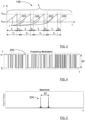
- Figure 4 illustrates the binary code 300 as a function of frequency and time
- Figure 5 illustrates the binary code 300 spectrally as a functions of signal power amplitude and frequency.
- the binary code 300 is thus in this example represented by a BFSK modulated signal.
- phase ⁇ c of the BFSK modulated signal as a function of time corresponds to an integral of the binary code 300 as a function of time as illustrated in Figure 9 . It is to be noted that the phase is a property of the BFSK modulated signal, modulated by the binary code 300, and not the binary code itself.
- the transmitter unit 140 comprises a ramp generator unit 146 adapted to generate the ramps r, and a code generator unit 147 adapted to generate the binary code 300.
- the receiver unit 141 comprises a mixer unit 150 adapted to mix the transmitted radar signal 108 with the received radar signal 109 and to output an analogue intermediate frequency, IF, signal 156.
- the transmitted code phase ⁇ cTX is proportional to the time integral of the BFSK binary code 300 in the transmitted signal 108, and the received code phase ⁇ cRX , corresponds to the transmitted code phase ⁇ cTX having been subject to a time shift t s , or delay, as illustrated in Figure 10 , where this time shift t s creates the difference between the transmitted code phase ⁇ cTX and the received code phase ⁇ cRX .
- the IF code phase ⁇ cIF is a derivative of the phase ⁇ c of the binary code 300, such that a corresponding binary phase code 300' is obtained, being a phase function of the received signal and varying between two phase values ⁇ 1 , ⁇ 2 in a phase span ⁇ .
- binary phase code 300' the binary code is represented by a BPSK, Binary Phase Shift Keying, modulated signal.
- the receiver unit 141 further comprises an analogue to digital converter, ADC, unit 152 adapted to output a digital IF signal 157 that is illustrated in Figure 7 , a correlation unit 153, and a re-sampling unit 154.
- ADC analogue to digital converter
- the correlation unit 153 is adapted to perform a correlation calculation between the digital IF signal 157 and the original binary code 300 provided by the code generator unit 147 such that a correlation function 600 is obtained, where the correlation unit 153 is adapted to separate the signal part comprising the binary code 300 from the signal parts comprising the ramps r by means of the correlation function 600.
- the correlation unit 153 is further adapted to provide synchronization information 158 regarding start times for the ramps r in the transmitted radar signal 108 and corresponding ramps in the received radar signal 109.
- the synchronization information 158 is output to the re-sampling unit 154 that is adapted to provide a re-sampled digital IF signal 159 where the binary code 300 has been removed, only the signal parts comprising the ramps r remaining.
- the re-sampled digital IF signal 159 is forwarded for further processing, for example to a digital signal processing (DSP) unit 155.
- DSP digital signal processing
- An output 180 from a DSP unit 155 can for example be forwarded to a vehicle safety system, an Autonomous Drive (AD) system and the like (not shown).
- the transmitter unit 140 comprises a switch unit 145 that is connected to a transmitter antenna arrangement 142 and is adapted to switch between a ramp generator unit 146 adapted to generate the ramps r, and a code generator unit 147 adapted to generate the binary code 300, such that the code generator 147 is connected to the transmitter antenna arrangement 142 within the delay times t D .
- the switch unit 145 can be realized in hardware, in software, or in a combination of both, in previously known ways.
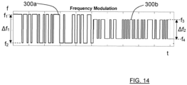
- the binary code 300a, 300b is of the type BFSK, Binary Frequency Shift Keying, where the digital signs in the binary code consists of two separately identifiable binary code sequences 300a, 300b, where the binary code sequences 300a, 300b vary between a first set of two different frequencies f 1 , f 2 in a first frequency span ⁇ f 1 and a second set of two different frequencies f 3 , f 4 in a second frequency span ⁇ f 2 , respectively.
- the correlation unit 153 is arranged to combine the results of correlating the received signal with each binary code 300a, 300b.
- the receiver unit 141 might choose to use the binary code 300a, 300b that inhibits the largest power out of all the binary codes 300a, 300b available for the resampling procedure.
- frequency span ⁇ f 1 , ⁇ f 2 frequency diversity is achieved and the likelihood of correctly estimating the code-ramp transitions is increased.
- a known binary code 300 will be present in the received radar signal 109 and by modulating the frequency of a continuous wave signal using such binary codes 300 between every repetition of an FMCW waveform ramp r, a relatively low-complexity software that is one-dimensional and FFT-based can detect the binary codes 300 and then identify the start indices of each ramp r in the received radar signal 109 such that the data can be resampled before further processing.
- the phase ⁇ IF of the analogue IF signal 156 mainly is proportional to the derivative of the phase ⁇ TX of the transmitted radar signal 108.
- the phase ⁇ TX of the transmitted radar signal 108 should be defined as the integral of the binary code 300.
- the transmitted radar signal 108 should let the binary code 300 modulate its frequency.
- the code or chip rate is the same as the sampling rate of the ADC unit 152, but can also be equal to the sampling rate of the ADC unit 152 divided by an integer number. Keeping the code rate relatively large makes the code more easily distinguishable from the rest of the radar signal through high-pass filtering which improves performance.
- the present disclosure also relates to a method in a radar transceiver arrangement 101.
- the method comprises generating and transmitting S100 a radar signal 108 comprising a plurality of subsequent radar waveforms r with a delay time t D between each radar waveform r, and receiving S200 reflected radar signals 109.
- the method comprises generating and transmitting S300 a predetermined binary code 300 within each delay time t D , the binary code 300 being comprised in the transmitted radar signal 108.
- the binary code 300 is of the type BFSK, Binary Frequency Shift Keying, where the digital signs in the binary code vary between two different frequencies f 1 , f 2 in a frequency span ⁇ f.
- the method further comprises performing S400 a correlation procedure for the received radar signal 109 and the binary code 300, such that a correlation function 600 is obtained, and identifying S500 the parts of the received radar signal 109 that comprise the binary code 300.
- the method further comprises separating S600 the signal part comprising the binary code 300 from the signal parts comprising the ramps r by means of the correlation function 600.
- the method further comprises providing S700 synchronization information 158 regarding start times for the ramps r in the transmitted radar signal 108 and corresponding ramps in the received radar signal 109.
- the method further comprises providing a re-sampled digital IF signal 159.
- the binary code 300a, 300b is of the type BFSK, Binary Frequency Shift Keying, where the digital signs in the binary code consists of two separately identifiable code sequences 300a, 300b, where the code sequences 300a, 300b vary between a first set of two different frequencies f 1 , f 2 in a first frequency span ⁇ f 1 and a second set of two different frequencies f 3 , f 4 in a second frequency span ⁇ f 2 , respectively.
- the transceiver arrangement 101 may of course comprise other items that are obvious to the skilled person, only those necessary to explain the present disclosure have been identified and discussed. Examples of such other items are a transmitter amplifier arrangement 143, a receiver amplifier arrangement 149 and an anti-alias filter 151.
- FIG 12 schematically illustrates, in terms of a number of functional units, the components of a control unit 107 according to an embodiment.
- the control unit 107 may be constituted by one or more processor unit parts that can be separate from each other. Although each processor unit 107 is indicated to be positioned in the vehicle 100, some processor unit parts may for example be comprised in a remote server 160 or elsewhere.
- Processing circuitry 1020 is provided using any combination of one or more of a suitable central processing unit (CPU), multiprocessor, microcontroller, digital signal processor (DSP), dedicated hardware accelerator, etc., capable of executing software instructions stored in a computer program product, e.g. in the form of a storage medium 1021.
- the processing circuitry 1020 may further be provided as at least one application specific integrated circuit (ASIC), or field programmable gate array (FPGA) .
- ASIC application specific integrated circuit
- FPGA field programmable gate array
- the processing circuitry 1020 is configured to cause the control unit 107 to perform a set of operations, or steps. These operations, or steps, were discussed above in connection to the various vehicle radar systems and methods.
- the storage medium 1021 may store the set of operations
- the processing circuitry 1020 may be configured to retrieve the set of operations from the storage medium 1021 to cause the control unit 107 to perform the set of operations.
- the set of operations may be provided as a set of executable instructions.
- processing circuitry 1020 is thereby arranged to execute methods and operations as herein disclosed.
- the storage medium 1021 may also comprise persistent storage, which, for example, can be any single one or combination of magnetic memory, optical memory, solid state memory or even remotely mounted memory.
- the processing circuitry 1020 is adapted to control the general operation of the control unit 107 e.g., by sending data and control signals to the external unit and the storage medium 1021, by receiving data and reports from the external unit, and by retrieving data and instructions from the storage medium 1021.
- Other components, as well as the related functionality, of each control unit 107 are omitted in order not to obscure the concepts presented herein.
- Figure 13 shows a computer program product 1110 comprising computer executable instructions 1120 arranged on a computer readable medium 1130 to execute any of the methods disclosed herein.
- the present disclosure is not limited to the examples provided, but may vary freely within the scope of the appended claims.
- the binary code 300, 300a, 300b can for example also be regarded as a binary sequence or a binary code sequence.
- An example of a length of each binary code 300 is according to some aspects in the span ten microseconds to a hundred microseconds. This can depend on the sampling rate of the ADC unit 152.
Landscapes
- Engineering & Computer Science (AREA)
- Radar, Positioning & Navigation (AREA)
- Remote Sensing (AREA)
- Physics & Mathematics (AREA)
- Computer Networks & Wireless Communication (AREA)
- General Physics & Mathematics (AREA)
- Electromagnetism (AREA)
- Radar Systems Or Details Thereof (AREA)
Abstract
Description
- The present disclosure relates to synchronization of a receiver unit and a transmitter unit in a radar transceiver arrangement.
- A radar transceiver is a device arranged for transmission and reception of radar signals in a radar frequency band. Radar transceivers are commonly used in vehicles for monitoring vehicle surroundings. Automatic Cruise Control (ACC) functions, Emergency Braking (EB) functions, Advanced Driver Assistance Systems (ADAS) and Autonomous Drive (AD) are some examples of applications where radar data represents an important source of information on which vehicle control is based.
- A well-known type of radar transmission format is the frequency modulated continuous wave (FMCW) format. This type of radar waveform comprises a 'chirp' signal of linearly increasing or decreasing frequency. Typically, an FMCW radar transceiver transmits multiple consecutive chirps in a saw-tooth like pattern, where the down-mixed return signal from a target will be processed with a two-dimensional (2D) fast Fourier transform (FFT) to create a matrix of complex amplitudes where each matrix element corresponds to a given range and target speed, or Doppler frequency shift.
- By identifying local maxima in this matrix above a defined threshold, detections can be extracted from this matrix, each with an associated range and speed. This is normally referred to as the detection phase and is then followed by the angle of arrival estimation phase, where the phases of the receiver antennas are processed. An FMCW radar transceiver normally operates in cycles, where each cycle comprises a detection phase.
- The benefits of using FMCW radar waveforms are well known for automotive radar systems. An FMCW-based radar transceiver can cost efficiently support wide band performance, such as 1GHz sweeps, to deliver the capability to resolve two targets that are only on the order of 20cm in radial separation. The 77GHz radar band provides a worldwide 1GHz bandwidth allocation for such radar systems, which is an advantage when it comes to production volumes. FMCW radar transceivers also normally produce highly constrained frequency spectra, allowing efficient use of the available bandwidth, which is a further advantage. There are similar waveforms where the above also is applicable, for example SFCW, Stepped Frequency Continuous Wave.
- As mentioned, the transmitted signal consists of multiple consecutive chirps and the return signal of each chirp is sampled by an analogue to digital converter. To achieve an accurate measurement, it is important that each digital sample can be associated with its corresponding chirp.
- This requires that a radar transmitter and a radar receiver are fully synchronized. Here, fully synchronized means that
- a) the transmitter and the receiver operate on a common smallest time-base, and that
- b) the receiver knows what digital samples can be associated with the very beginning and end of each chirp produced by the transmitter such that the overall, repeated structure can be inferred.
- Regarding (b), this need can for example be addressed by means of an additional synchronization/triggering signal in hardware, but there is a desire to reduce the complexity in radar hardware.
- It is therefore an object of the present disclosure to provide a radar transceiver arrangement where the receiver and transmitter of a radar system are sufficiently synchronized according to the above.
- This object is obtained by means of a radar transceiver arrangement comprising a control unit, a transmitter unit and a receiver unit. The transmitter unit is adapted to generate and transmit a radar signal comprising a plurality of subsequent radar waveforms with a delay time between each radar waveform. The receiver unit is adapted to receive reflected radar signals. For at least a subset of the transmitted radar waveforms, the radar transceiver arrangement is adapted to generate and transmit a predetermined binary code within each delay time, the binary code being comprised in the transmitted radar signal.
- This enables the radar transceiver arrangement to determine which digital samples that can be associated with the very beginning and end of each transmitted radar waveforms produced by the transmitter unit such that the overall, repeated structure can be inferred.
- According to some aspects, the radar waveforms are constituted by FMCW, Frequency Modulated Continuous Wave, ramps, where, for at least a subset of the ramps, the radar transceiver arrangement is adapted to generate and transmit the binary code in the delay time between two subsequent ramps. This means that the present disclosure is applicable for FMCW that is a well-known and widely used radar waveform.
- According to some aspects, the binary code is of the type BFSK, Binary Frequency Shift Keying, where the digital signs in the binary code vary between two different frequencies in a frequency span. This means that a commonly known and easily produced digital code can be used, and where the binary code is highly suited for its purpose.
- According to some aspects, the radar transceiver arrangement is adapted to perform a correlation procedure for the received radar signal and the binary code, such that a correlation function is obtained and the parts of the received radar signal that comprise the binary code can be identified.
- According to some aspects, the transmitter unit comprises a ramp generator unit adapted to generate the ramps, and a code generator unit adapted to generate the binary code. The receiver unit comprises a mixer unit adapted to mix the transmitted radar signal with the received radar signal and to output an analogue intermediate frequency, IF, signal. The receiver unit further comprises an analogue to digital converter, ADC, unit adapted to output a digital IF signal, a correlation unit, and a re-sampling unit.
- The correlation unit is adapted to perform a correlation calculation between the digital IF signal and the original binary code provided by the code generator unit such that a correlation function is obtained. The correlation unit is adapted to separate the signal part comprising the binary code from the signal parts comprising the ramps by means of the correlation function and to provide synchronization information regarding start times for the ramps in the transmitted radar signal and corresponding ramps in the received radar signal.
- This means that at the transmitter unit, the binary code is embedded in the frequency when using BFSK. A derivation action that provides an IF code phase ϕcIF = ϕcTX - ϕcRX, together with waveform designs choices such as for example duration, length of the digital levels, frequency steps etc., can be viewed as turning the original BFSK into a phase modulation, BPSK, at the receiver unit. So, at the receiver unit, the sampled data can be correlated the with a BPSK version of the binary code.
- According to some aspects, the synchronization information is output to the re-sampling unit that is adapted to provide a re-sampled digital IF signal. The re-sampled digital IF signal can be forwarded for further processing, for example to a digital signal processing (DSP) unit.
- According to some aspects, the transmitter unit comprises a switch unit that is connected to a transmitter antenna arrangement. The switch unit is adapted to switch between a ramp generator unit adapted to generate the ramps, and a code generator unit adapted to generate the binary code, such that the code generator is connected to the transmitter antenna arrangement within the delay times. In this way an efficient and reliable way to embed the binary code in the transmitted radar signal is provided. The switch unit can be realized in hardware, in software, or in a combination of both, in previously known ways.
- According to some aspects, the binary code is of the type BFSK, Binary Frequency Shift Keying, where the digital signs in the binary code consist of two separately identifiable binary code sequences, where the binary code sequences vary between a first set of two different frequencies in a first frequency span and a second set of two different frequencies in a second frequency span, respectively.
- This is advantageous in multi-target scenarios where the power of the received binary code sequence can be drastically reduced if the resulting radar channel inhibits frequency selectivity, known as fading. In order to increase the radar transceiver arrangement's robustness to fading effects, two or more different binary code sequences can be used and each is assigned a unique modulation frequency span.
- There are also disclosed herein methods and vehicles associated with the above-mentioned advantages.
- The present disclosure will now be described more in detail with reference to the appended drawings, where:
- Figure 1
- shows a schematic top view of a vehicle;
- Figure 2
- shows a schematic illustration of a radar transceiver arrangement;
- Figure 3
- schematically shows a transmitted radar signal;
- Figure 4
- schematically shows a first example of a binary code;
- Figure 5
- schematically shows a spectrum of the binary code in
Figure 4 ; - Figure 6
- schematically shows a correlation function for a received radar signal and the binary code;
- Figure 7
- schematically shows a digital IF signal;
- Figure 8
- schematically shows a re-sampled digital IF signal;
- Figure 9
- schematically shows a binary code and its phase;
- Figure 10
- schematically shows a resulting binary code after mixing;
- Figure 11
- is a flow chart illustrating methods;
- Figure 12
- shows an example control unit;
- Figure 13
- shows an example computer program product; and
- Figure 14
- schematically shows a second example of a binary code.
- The inventive concept will now be described more fully hereinafter with reference to the accompanying drawings, in which certain embodiments of the inventive concept are shown. This inventive concept may, however, be embodied in many different forms and should not be construed as limited to the embodiments set forth herein; rather, these embodiments are provided by way of example so that this disclosure will be thorough and complete, and will fully convey the scope of the inventive concept to those skilled in the art.
- Like numbers refer to like elements throughout the description. Any step or feature illustrated by dashed lines should be regarded as optional.
-
Figure 1 shows avehicle 100 equipped with a vehicleradar transceiver arrangement 101. With reference also toFigure 2 and Figure 2 , thetransceiver arrangement 101 comprises acontrol unit 107, atransmitter unit 140 and areceiver unit 141, where thetransmitter unit 140 is adapted to generate and transmit aradar signal 108 comprising a plurality of subsequent radar waveforms r with a delay time tD between each radar waveform r. Thereceiver unit 141 is adapted to receive reflected radar signals 109, where the transmittedsignals 108 have been reflected by anobject 110. - In a previously well-known manner, the
transceiver arrangement 101 is normally associated with an effective field ofview 130 and by means of signal processing where digital samples are determined for the receivedradar signals 109, range andtarget angle 112 relative areference line 111, to detectedobjects 110 can be determined. - The
transceiver arrangement 101 may according to some aspects be connected viawireless link 162 to aremote server 160, which in turn may be comprised in a cloud-basedresource 161 or remote network. Thisserver 160 and network may be configured to assist thecontrol unit 107 in performing various operations such as radar signal processing, interference mitigation, beamforming, and the like. Some parts of the functionality of thetransceiver arrangement 100 may thus be comprised in aremote server 160 or cloud-basedresource 161. - For this reason, the
control unit 107 may be arranged to communicate 162 with acellular communication system 163. Thiscommunication system 163 may, e.g., be a third generation partnership program (3GPP) defined access network like the fourth generation (4G) or the fifth generation (5G) access networks. The access network may provide access to remote networks and other resources such as, e.g., theInternet 161. - According to the present disclosure, with reference also to
Figure 4 and Figure 5 , for at least a subset of the transmitted radar waveforms r, theradar transceiver arrangement 101 is adapted to generate and transmit a predeterminedbinary code 300 within each delay time tD, thebinary code 300 being comprised in the transmittedradar signal 108. - This enables the
radar transceiver arrangement 101 to determine which digital samples that can be associated with the very beginning and end of each transmitted radar waveforms r produced by thetransmitter unit 140 such that the overall, repeated structure can be inferred. Examples of how this can be achieved practically are disclosed later. - According to some aspects, as shown in
Figure 3 , the radar waveforms are constituted by FMCW, Frequency Modulated Continuous Wave, ramps r, where, for at least a subset of the ramps r, theradar transceiver arrangement 101 is adapted to generate and transmit thebinary code 300 in the delay time tD between two subsequent ramps r. This means that the present disclosure is applicable for FMCW that is a well-known and widely used radar waveform. - It should be noted that the present disclosure is not limited to FMCW radar waveforms. Rather, the general concepts and techniques disclosed herein can be adapted and applied to other suitable radar waveforms such as for example for example SFCW, Stepped Frequency Continuous Wave ramps.
- According to some aspects, as shown in
Figure 4 and Figure 5 , thebinary code 300 is of the type BFSK, Binary Frequency Shift Keying, where the digital signs in the binary code vary between two different frequencies f1, f2 in a frequency span Δf.Figure 4 illustrates thebinary code 300 as a function of frequency and time, andFigure 5 illustrates thebinary code 300 spectrally as a functions of signal power amplitude and frequency. Thebinary code 300 is thus in this example represented by a BFSK modulated signal. - In this example, when it is referred to the
binary code 300, it is referred to the binary code as represented by the BFSK modulatedsignal 300. Thebinary code 300 being of the type BFSK thus means that the binary code is represented by means of BFSK. Generally, when it is referred to the binary code, it can relate to both the binary code itself and its present representation. - This means that a commonly known and easily produced digital code can be used, and where the
binary code 300 is highly suited for its purpose. Furthermore, the phase ϕc of the BFSK modulated signal as a function of time corresponds to an integral of thebinary code 300 as a function of time as illustrated inFigure 9 . It is to be noted that the phase is a property of the BFSK modulated signal, modulated by thebinary code 300, and not the binary code itself. - According to some aspects, as shown in
Figure 6 , theradar transceiver arrangement 101 is adapted to perform a correlation procedure for the receivedradar signal 109 and thebinary code 300, such that acorrelation function 600 is obtained and the parts of the receivedradar signal 109 that comprise thebinary code 300 can be identified. An example of this, where thebinary code 300 is represented by the BFSK modulated signal as described above, will be described more in detail in the following. - According to some aspects, with reference to
Figure 2 - Figure 8 , thetransmitter unit 140 comprises aramp generator unit 146 adapted to generate the ramps r, and acode generator unit 147 adapted to generate thebinary code 300. Thereceiver unit 141 comprises amixer unit 150 adapted to mix the transmittedradar signal 108 with the receivedradar signal 109 and to output an analogue intermediate frequency, IF, signal 156. - After mixing, the phase ϕIF of the analogue IF
signal 156 is a difference of the phase ϕTX of the transmittedradar signal 108 and the phase ϕRX the receivedradar signal 109 such that ϕIF = ϕTX - ϕRX. For thebinary code 300 this means that the analogue IFsignal 156 comprises an IF code phase ϕcIF that is a difference between a transmitted code phase ϕcTX in the transmittedsignal 108 and a received code phase ϕcRX in the receivedsignal 109, such that the IF code phase ϕcIF = ϕcTX - ϕcRX. - The transmitted code phase ϕcTX is proportional to the time integral of the BFSK
binary code 300 in the transmittedsignal 108, and the received code phase ϕcRX, corresponds to the transmitted code phase ϕcTX having been subject to a time shift ts, or delay, as illustrated inFigure 10 , where this time shift ts creates the difference between the transmitted code phase ϕcTX and the received code phase ϕcRX. - This results in that the IF code phase ϕcIF is a derivative of the phase ϕc of the
binary code 300, such that a corresponding binary phase code 300' is obtained, being a phase function of the received signal and varying between two phase values ϕ1, ϕ2 in a phase span Δϕ. For binary phase code 300' the binary code is represented by a BPSK, Binary Phase Shift Keying, modulated signal. - The
receiver unit 141 further comprises an analogue to digital converter, ADC,unit 152 adapted to output a digital IFsignal 157 that is illustrated inFigure 7 , acorrelation unit 153, and are-sampling unit 154. - The
correlation unit 153 is adapted to perform a correlation calculation between the digital IFsignal 157 and the originalbinary code 300 provided by thecode generator unit 147 such that acorrelation function 600 is obtained, where thecorrelation unit 153 is adapted to separate the signal part comprising thebinary code 300 from the signal parts comprising the ramps r by means of thecorrelation function 600. Thecorrelation unit 153 is further adapted to providesynchronization information 158 regarding start times for the ramps r in the transmittedradar signal 108 and corresponding ramps in the receivedradar signal 109. - According to some aspects, this means that at the
transmitter unit 140, the binary code is embedded in the frequency using BFSK. The following derivation action providing IF code phase ϕcIF = ϕcTX - ϕcRX, together with waveform designs choices such as for example duration, length of the digital levels, frequency steps etc., can be viewed as turning the original BFSK into a phase modulation, BPSK, at thereceiver unit 141. So, at thereceiver unit 141 the sampled data is correlated the with a BPSK version of the binary code. - According to some aspects, the
synchronization information 158 is output to there-sampling unit 154 that is adapted to provide a re-sampled digital IFsignal 159 where thebinary code 300 has been removed, only the signal parts comprising the ramps r remaining. The re-sampled digital IFsignal 159 is forwarded for further processing, for example to a digital signal processing (DSP)unit 155. Anoutput 180 from aDSP unit 155 can for example be forwarded to a vehicle safety system, an Autonomous Drive (AD) system and the like (not shown). - According to some aspects, the
transmitter unit 140 comprises aswitch unit 145 that is connected to atransmitter antenna arrangement 142 and is adapted to switch between aramp generator unit 146 adapted to generate the ramps r, and acode generator unit 147 adapted to generate thebinary code 300, such that thecode generator 147 is connected to thetransmitter antenna arrangement 142 within the delay times tD. Theswitch unit 145 can be realized in hardware, in software, or in a combination of both, in previously known ways. - According to some aspects, with reference to
Figure 14 , thebinary code binary code sequences binary code sequences - This is advantageous in multi-target scenarios where the power of the received code sequence can be drastically reduced if the resulting radar channel inhibits frequency selectivity, known as fading. In order to increase the radar transceiver arrangement's robustness to fading effects, two or more different binary code sequences can be used and each is assigned a unique modulation frequency span Δf1, Δf2.
- At the
receiver unit 141, thecorrelation unit 153 is arranged to combine the results of correlating the received signal with eachbinary code receiver unit 141 might choose to use thebinary code binary codes - By means of the present disclosure, complexity is moved from hardware into software and waveform generation steps, requiring no additional hardware trigger signals and receive channels.
- According to some aspects, a known
binary code 300 will be present in the receivedradar signal 109 and by modulating the frequency of a continuous wave signal using suchbinary codes 300 between every repetition of an FMCW waveform ramp r, a relatively low-complexity software that is one-dimensional and FFT-based can detect thebinary codes 300 and then identify the start indices of each ramp r in the receivedradar signal 109 such that the data can be resampled before further processing. As briefly discussed above, the phase ϕIF of the analogue IFsignal 156 mainly is proportional to the derivative of the phase ϕTX of the transmittedradar signal 108. - Therefore, in order to achieve a known code sequence in the analogue IF
signal 156, the phase ϕTX of the transmittedradar signal 108 should be defined as the integral of thebinary code 300. In other words, to achieve the binary code as a phase modulation in the analogue IFsignal 156, the transmittedradar signal 108 should let thebinary code 300 modulate its frequency. - According to some aspects, the code or chip rate is the same as the sampling rate of the
ADC unit 152, but can also be equal to the sampling rate of theADC unit 152 divided by an integer number. Keeping the code rate relatively large makes the code more easily distinguishable from the rest of the radar signal through high-pass filtering which improves performance. - With reference to
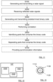
Figure 11 , the present disclosure also relates to a method in aradar transceiver arrangement 101. The method comprises generating and transmitting S100 aradar signal 108 comprising a plurality of subsequent radar waveforms r with a delay time tD between each radar waveform r, and receiving S200 reflected radar signals 109. For at least a subset of the transmitted radar waveforms r, the method comprises generating and transmitting S300 a predeterminedbinary code 300 within each delay time tD, thebinary code 300 being comprised in the transmittedradar signal 108. - According to some aspects, the
binary code 300 is of the type BFSK, Binary Frequency Shift Keying, where the digital signs in the binary code vary between two different frequencies f1, f2 in a frequency span Δf. - According to some aspects, the method further comprises performing S400 a correlation procedure for the received
radar signal 109 and thebinary code 300, such that acorrelation function 600 is obtained, and identifying S500 the parts of the receivedradar signal 109 that comprise thebinary code 300. - According to some aspects, the method further comprises separating S600 the signal part comprising the
binary code 300 from the signal parts comprising the ramps r by means of thecorrelation function 600. The method further comprises providingS700 synchronization information 158 regarding start times for the ramps r in the transmittedradar signal 108 and corresponding ramps in the receivedradar signal 109. - According to some aspects, the method further comprises providing a re-sampled digital IF
signal 159. - According to some aspects, the
binary code identifiable code sequences code sequences - With reference to
Figure 2 , thetransceiver arrangement 101 may of course comprise other items that are obvious to the skilled person, only those necessary to explain the present disclosure have been identified and discussed. Examples of such other items are atransmitter amplifier arrangement 143, areceiver amplifier arrangement 149 and ananti-alias filter 151. -
Figure 12 schematically illustrates, in terms of a number of functional units, the components of acontrol unit 107 according to an embodiment. Thecontrol unit 107 may be constituted by one or more processor unit parts that can be separate from each other. Although eachprocessor unit 107 is indicated to be positioned in thevehicle 100, some processor unit parts may for example be comprised in aremote server 160 or elsewhere. -
Processing circuitry 1020 is provided using any combination of one or more of a suitable central processing unit (CPU), multiprocessor, microcontroller, digital signal processor (DSP), dedicated hardware accelerator, etc., capable of executing software instructions stored in a computer program product, e.g. in the form of astorage medium 1021. Theprocessing circuitry 1020 may further be provided as at least one application specific integrated circuit (ASIC), or field programmable gate array (FPGA) . - Particularly, the
processing circuitry 1020 is configured to cause thecontrol unit 107 to perform a set of operations, or steps. These operations, or steps, were discussed above in connection to the various vehicle radar systems and methods. For example, thestorage medium 1021 may store the set of operations, and theprocessing circuitry 1020 may be configured to retrieve the set of operations from thestorage medium 1021 to cause thecontrol unit 107 to perform the set of operations. The set of operations may be provided as a set of executable instructions. - Thus, the
processing circuitry 1020 is thereby arranged to execute methods and operations as herein disclosed. - The
storage medium 1021 may also comprise persistent storage, which, for example, can be any single one or combination of magnetic memory, optical memory, solid state memory or even remotely mounted memory. - Each
control unit 107 may further comprise acommunications interface 1022 for communications with at least one other unit such as for example other parts in the radar transceiver units. As such, thecommunications interface 1022 may comprise one or more transmitters and receivers, comprising analogue and digital components and a suitable number of ports for wired or wireless communication. - The
processing circuitry 1020 is adapted to control the general operation of thecontrol unit 107 e.g., by sending data and control signals to the external unit and thestorage medium 1021, by receiving data and reports from the external unit, and by retrieving data and instructions from thestorage medium 1021. Other components, as well as the related functionality, of eachcontrol unit 107 are omitted in order not to obscure the concepts presented herein. -
Figure 13 shows acomputer program product 1110 comprising computerexecutable instructions 1120 arranged on a computer readable medium 1130 to execute any of the methods disclosed herein. - The present disclosure is not limited to the examples provided, but may vary freely within the scope of the appended claims. The
binary code binary code 300 is according to some aspects in the span ten microseconds to a hundred microseconds. This can depend on the sampling rate of theADC unit 152. - According to some aspects, the integrations and derivations discussed are to be regarded as approximations and not as being mathematical exact.
Claims (15)
- A radar transceiver arrangement (101) comprising a control unit (107), a transmitter unit (140) and a receiver unit (141), where the transmitter unit (140) is adapted to generate and transmit a radar signal (108) comprising a plurality of subsequent radar waveforms (r) with a delay time (tD) between each radar waveform (r), and where the receiver unit (141) is adapted to receive reflected radar signals (109), characterized in that, for at least a subset of the transmitted radar waveforms (r), the radar transceiver arrangement (101) is adapted to generate and transmit a predetermined binary code (300) within each delay time (tD), the binary code (300) being comprised in the transmitted radar signal (108).
- The radar transceiver arrangement (101) according to claim 1, wherein the radar waveforms are constituted by FMCW, Frequency Modulated Continuous Wave, ramps (r), where, for at least a subset of the ramps (r), the radar transceiver arrangement (101) is adapted to generate and transmit the binary code (300) in the delay time (tD) between two subsequent ramps (r) .
- The radar transceiver arrangement (101) according to any one of the claims 1 or 2, wherein the binary code (300) is of the type BFSK, Binary Frequency Shift Keying, where the digital signs in the binary code vary between two different frequencies (f1, f2) in a frequency span (Δf).
- The radar transceiver arrangement (101) according to any one of the previous claims, wherein the radar transceiver arrangement (101) is adapted to perform a correlation procedure for the received radar signal (109) and the binary code (300), such that a correlation function (600) is obtained and the parts of the received radar signal (109) that comprise the binary code (300) can be identified.
- The radar transceiver arrangement (101) according to any one of the previous claims, wherein the transmitter unit (140) comprises- a ramp generator unit (146) adapted to generate the ramps (r), and- a code generator unit (147) adapted to generate the binary code (300),
and where the receiver unit (141) comprises- a mixer unit (150) adapted to mix the transmitted radar signal (108) with the received radar signal (109) and to output an analogue intermediate frequency, IF, signal (156),- an analogue to digital converter, ADC, unit (152) adapted to output a digital IF signal (157),- a correlation unit (153), and- a re-sampling unit (154),where the correlation unit (153) is adapted to perform a correlation calculation between the digital IF signal (157) and the original binary code (300) provided by the code generator unit (147) such that a correlation function (600) is obtained, where the correlation unit (153) is adapted to separate the signal part comprising the binary code (300) from the signal parts comprising the ramps (r) by means of the correlation function (600) and to provide synchronization information (158) regarding start times for the ramps (r) in the transmitted radar signal (108) and corresponding ramps in the received radar signal (109) . - The radar transceiver arrangement (101) according to claim 5, wherein the synchronization information (158) is output to the re-sampling unit (154) that is adapted to provide a resampled digital IF signal (159).
- The radar transceiver arrangement (101) according to any one of the previous claims, wherein the transmitter unit (140) comprises a switch unit (145) that is connected to a transmitter antenna arrangement (142) and is adapted to switch between a ramp generator unit (146) adapted to generate the ramps (r), and a code generator unit (147) adapted to generate the binary code (300), such that the code generator (147) is connected to the transmitter antenna arrangement (142) within the delay times (tD).
- The radar transceiver arrangement (101) according to any one of the previous claims, wherein the binary code (300a, 300b) is of the type BFSK, Binary Frequency Shift Keying, where the digital signs in the binary code consists of two separately identifiable binary code sequences (300a, 300b), where the binary code sequences (300a, 300b) vary between a first set of two different frequencies (f1, f2) in a first frequency span (Δf1) and a second set of two different frequencies (f3, f4) in a second frequency span (Δf2), respectively.
- A vehicle (100) comprising the radar transceiver arrangement (101) according to any previous claim.
- A method in a radar transceiver arrangement (101), where the method comprisesgenerating and transmitting (S100) a radar signal (108) comprising a plurality of subsequent radar waveforms (r) with a delay time (tD) between each radar waveform (r); andreceiving (S200) reflected radar signals (109);
wherein, for at least a subset of the transmitted radar waveforms (r), the method comprisesgenerating and transmitting (S300) a predetermined binary code (300) within each delay time (tD), the binary code (300) being comprised in the transmitted radar signal (108). - The method according to claim 10, wherein the binary code (300) is of the type BFSK, Binary Frequency Shift Keying, where the digital signs in the binary code vary between two different frequencies (f1, f2) in a frequency span (Δf) .
- The method according to any one of the claims 10 or 11, wherein the method further comprisesperforming (S400) a correlation procedure for the received radar signal (109) and the binary code (300), such that a correlation function (600) is obtained; andidentifying (S500) the parts of the received radar signal (109) that comprise the binary code (300).
- The method according to claim 12, wherein the method further comprisesseparating (S600) the signal part comprising the binary code (300) from the signal parts comprising the ramps (r) by means of the correlation function (600); andproviding (S700) synchronization information (158) regarding start times for the ramps (r) in the transmitted radar signal (108) and corresponding ramps in the received radar signal (109) .
- The method according to claim 13, wherein the method further comprises providing a re-sampled digital IF signal (159) .
- The method according to any one of the claims 10-14, wherein the binary code (300a, 300b) is of the type BFSK, Binary Frequency Shift Keying, where the digital signs in the binary code consists of two separately identifiable code sequences (300a, 300b), where the code sequences (300a, 300b) vary between a first set of two different frequencies (f1, f2) in a first frequency span (Δf1) and a second set of two different frequencies (f3, f4) in a second frequency span (Δf2), respectively.
Priority Applications (2)
| Application Number | Priority Date | Filing Date | Title |
|---|---|---|---|
| EP23176715.3A EP4471455B1 (en) | 2023-06-01 | 2023-06-01 | Synchronization of a receiver unit and a transmitter unit in a radar transceiver arrangement |
| PCT/EP2024/064226 WO2024245888A1 (en) | 2023-06-01 | 2024-05-23 | Synchronization of a receiver unit and a transmitter unit in a radar transceiver arrangement |
Applications Claiming Priority (1)
| Application Number | Priority Date | Filing Date | Title |
|---|---|---|---|
| EP23176715.3A EP4471455B1 (en) | 2023-06-01 | 2023-06-01 | Synchronization of a receiver unit and a transmitter unit in a radar transceiver arrangement |
Publications (2)
| Publication Number | Publication Date |
|---|---|
| EP4471455A1 true EP4471455A1 (en) | 2024-12-04 |
| EP4471455B1 EP4471455B1 (en) | 2025-12-24 |
Family
ID=86657607
Family Applications (1)
| Application Number | Title | Priority Date | Filing Date |
|---|---|---|---|
| EP23176715.3A Active EP4471455B1 (en) | 2023-06-01 | 2023-06-01 | Synchronization of a receiver unit and a transmitter unit in a radar transceiver arrangement |
Country Status (2)
| Country | Link |
|---|---|
| EP (1) | EP4471455B1 (en) |
| WO (1) | WO2024245888A1 (en) |
Citations (2)
| Publication number | Priority date | Publication date | Assignee | Title |
|---|---|---|---|---|
| EP3056920A1 (en) * | 2015-02-11 | 2016-08-17 | Autoliv Development AB | A vehicle radar system with two transceiver arrangements |
| EP3748997A1 (en) * | 2018-04-28 | 2020-12-09 | Huawei Technologies Co., Ltd. | Method for realizing radar-communication integration of vehicle, and related device and system |
-
2023
- 2023-06-01 EP EP23176715.3A patent/EP4471455B1/en active Active
-
2024
- 2024-05-23 WO PCT/EP2024/064226 patent/WO2024245888A1/en not_active Ceased
Patent Citations (2)
| Publication number | Priority date | Publication date | Assignee | Title |
|---|---|---|---|---|
| EP3056920A1 (en) * | 2015-02-11 | 2016-08-17 | Autoliv Development AB | A vehicle radar system with two transceiver arrangements |
| EP3748997A1 (en) * | 2018-04-28 | 2020-12-09 | Huawei Technologies Co., Ltd. | Method for realizing radar-communication integration of vehicle, and related device and system |
Also Published As
| Publication number | Publication date |
|---|---|
| WO2024245888A1 (en) | 2024-12-05 |
| EP4471455B1 (en) | 2025-12-24 |
Similar Documents
| Publication | Publication Date | Title |
|---|---|---|
| EP4009074B1 (en) | Co-prime coded (cpc) doppler division multiplexing (ddm) mimo radar method and system | |
| US20210255278A1 (en) | Distributed radar sensor system | |
| US9971028B2 (en) | Method and apparatus for detecting target using radar | |
| KR101137038B1 (en) | Radar apparatus, antenna appartus and data acquisition method | |
| KR101137088B1 (en) | Integrated Radar Apparatus and Integrated Antenna Apparatus | |
| CN113567928A (en) | MIMO radar apparatus and MIMO radar method | |
| CN102224432B (en) | Method and apparatus for radar signal processing | |
| US10162049B2 (en) | Method for operating a radar apparatus | |
| CN112578342B (en) | Signal sending method, signal processing method and radar device | |
| CN111157981A (en) | Multiple Input Multiple Output Frequency Modulated Continuous Wave Radar System | |
| JP3241975U (en) | MIMO radar device | |
| CN112578341B (en) | Signal sending method, signal processing method and device | |
| JP2009257884A (en) | Radar device | |
| EP4105685A1 (en) | Signal processing method and apparatus | |
| CN118191818A (en) | Target speed and distance determination method, device and radar | |
| EP4471455B1 (en) | Synchronization of a receiver unit and a transmitter unit in a radar transceiver arrangement | |
| KR102226885B1 (en) | Radar system operation method and radar system with improved range resolution by mutually delayed orthogonal codes | |
| KR20190135267A (en) | Continuous wave radar and ranging method using the continuous wave radar | |
| CN114755637B (en) | Interference identification method and device | |
| CN110531358B (en) | Information measuring method and information measuring device | |
| EP3819662B1 (en) | A vehicle radar with frequency diversity | |
| KR20200053222A (en) | Radar apparatus and radar signal processing method for precise measurement of distance, angular velocity | |
| EP4498112A1 (en) | Windowing in a radar tranceiver | |
| CN114859302A (en) | Interference interception method and device and radar | |
| KR101939614B1 (en) | Apparatus and method for assuming parameter of fmcw radar system |
Legal Events
| Date | Code | Title | Description |
|---|---|---|---|
| PUAI | Public reference made under article 153(3) epc to a published international application that has entered the european phase |
Free format text: ORIGINAL CODE: 0009012 |
|
| STAA | Information on the status of an ep patent application or granted ep patent |
Free format text: STATUS: THE APPLICATION HAS BEEN PUBLISHED |
|
| AK | Designated contracting states |
Kind code of ref document: A1 Designated state(s): AL AT BE BG CH CY CZ DE DK EE ES FI FR GB GR HR HU IE IS IT LI LT LU LV MC ME MK MT NL NO PL PT RO RS SE SI SK SM TR |
|
| STAA | Information on the status of an ep patent application or granted ep patent |
Free format text: STATUS: REQUEST FOR EXAMINATION WAS MADE |
|
| 17P | Request for examination filed |
Effective date: 20250522 |
|
| GRAP | Despatch of communication of intention to grant a patent |
Free format text: ORIGINAL CODE: EPIDOSNIGR1 |
|
| STAA | Information on the status of an ep patent application or granted ep patent |
Free format text: STATUS: GRANT OF PATENT IS INTENDED |
|
| INTG | Intention to grant announced |
Effective date: 20250715 |
|
| GRAS | Grant fee paid |
Free format text: ORIGINAL CODE: EPIDOSNIGR3 |
|
| GRAA | (expected) grant |
Free format text: ORIGINAL CODE: 0009210 |
|
| STAA | Information on the status of an ep patent application or granted ep patent |
Free format text: STATUS: THE PATENT HAS BEEN GRANTED |
|
| AK | Designated contracting states |
Kind code of ref document: B1 Designated state(s): AL AT BE BG CH CY CZ DE DK EE ES FI FR GB GR HR HU IE IS IT LI LT LU LV MC ME MK MT NL NO PL PT RO RS SE SI SK SM TR |
|
| REG | Reference to a national code |
Ref country code: CH Ref legal event code: F10 Free format text: ST27 STATUS EVENT CODE: U-0-0-F10-F00 (AS PROVIDED BY THE NATIONAL OFFICE) Effective date: 20251224 Ref country code: GB Ref legal event code: FG4D |
|
| REG | Reference to a national code |
Ref country code: DE Ref legal event code: R096 Ref document number: 602023009996 Country of ref document: DE |
|
| REG | Reference to a national code |
Ref country code: LT Ref legal event code: MG9D |
|
| PG25 | Lapsed in a contracting state [announced via postgrant information from national office to epo] |
Ref country code: NO Free format text: LAPSE BECAUSE OF FAILURE TO SUBMIT A TRANSLATION OF THE DESCRIPTION OR TO PAY THE FEE WITHIN THE PRESCRIBED TIME-LIMIT Effective date: 20260324 |
|
| PG25 | Lapsed in a contracting state [announced via postgrant information from national office to epo] |
Ref country code: FI Free format text: LAPSE BECAUSE OF FAILURE TO SUBMIT A TRANSLATION OF THE DESCRIPTION OR TO PAY THE FEE WITHIN THE PRESCRIBED TIME-LIMIT Effective date: 20251224 Ref country code: HR Free format text: LAPSE BECAUSE OF FAILURE TO SUBMIT A TRANSLATION OF THE DESCRIPTION OR TO PAY THE FEE WITHIN THE PRESCRIBED TIME-LIMIT Effective date: 20251224 |
|
| PG25 | Lapsed in a contracting state [announced via postgrant information from national office to epo] |
Ref country code: RS Free format text: LAPSE BECAUSE OF FAILURE TO SUBMIT A TRANSLATION OF THE DESCRIPTION OR TO PAY THE FEE WITHIN THE PRESCRIBED TIME-LIMIT Effective date: 20260324 |
|
| PG25 | Lapsed in a contracting state [announced via postgrant information from national office to epo] |
Ref country code: LV Free format text: LAPSE BECAUSE OF FAILURE TO SUBMIT A TRANSLATION OF THE DESCRIPTION OR TO PAY THE FEE WITHIN THE PRESCRIBED TIME-LIMIT Effective date: 20251224 |
|
| REG | Reference to a national code |
Ref country code: NL Ref legal event code: MP Effective date: 20251224 |
|
| PG25 | Lapsed in a contracting state [announced via postgrant information from national office to epo] |
Ref country code: BG Free format text: LAPSE BECAUSE OF FAILURE TO SUBMIT A TRANSLATION OF THE DESCRIPTION OR TO PAY THE FEE WITHIN THE PRESCRIBED TIME-LIMIT Effective date: 20251224 |