EP4471414A1 - Device, method, and program - Google Patents
Device, method, and program Download PDFInfo
- Publication number
- EP4471414A1 EP4471414A1 EP23747056.2A EP23747056A EP4471414A1 EP 4471414 A1 EP4471414 A1 EP 4471414A1 EP 23747056 A EP23747056 A EP 23747056A EP 4471414 A1 EP4471414 A1 EP 4471414A1
- Authority
- EP
- European Patent Office
- Prior art keywords
- output power
- temperature distribution
- light
- distribution
- temperature
- Prior art date
- Legal status (The legal status is an assumption and is not a legal conclusion. Google has not performed a legal analysis and makes no representation as to the accuracy of the status listed.)
- Pending
Links
- 238000000034 method Methods 0.000 title claims description 46
- 238000009826 distribution Methods 0.000 claims abstract description 338
- 230000006870 function Effects 0.000 claims description 13
- 230000001678 irradiating effect Effects 0.000 claims description 12
- 230000004044 response Effects 0.000 claims description 5
- 238000005259 measurement Methods 0.000 description 234
- 238000011156 evaluation Methods 0.000 description 94
- 238000010438 heat treatment Methods 0.000 description 72
- 238000004364 calculation method Methods 0.000 description 60
- 230000000737 periodic effect Effects 0.000 description 22
- 239000000463 material Substances 0.000 description 18
- 239000000835 fiber Substances 0.000 description 17
- 229910052799 carbon Inorganic materials 0.000 description 12
- 230000032798 delamination Effects 0.000 description 12
- OKTJSMMVPCPJKN-UHFFFAOYSA-N Carbon Chemical compound [C] OKTJSMMVPCPJKN-UHFFFAOYSA-N 0.000 description 11
- 239000003733 fiber-reinforced composite Substances 0.000 description 8
- 238000003860 storage Methods 0.000 description 8
- 239000003507 refrigerant Substances 0.000 description 7
- 238000009864 tensile test Methods 0.000 description 7
- 239000011347 resin Substances 0.000 description 6
- 229920005989 resin Polymers 0.000 description 6
- 238000012360 testing method Methods 0.000 description 6
- 238000000691 measurement method Methods 0.000 description 5
- 230000004075 alteration Effects 0.000 description 4
- 230000008859 change Effects 0.000 description 4
- 239000002131 composite material Substances 0.000 description 4
- 238000000113 differential scanning calorimetry Methods 0.000 description 4
- 238000012854 evaluation process Methods 0.000 description 4
- 238000009661 fatigue test Methods 0.000 description 4
- 239000011521 glass Substances 0.000 description 4
- 238000004519 manufacturing process Methods 0.000 description 4
- 230000007246 mechanism Effects 0.000 description 4
- 230000015556 catabolic process Effects 0.000 description 3
- 238000004891 communication Methods 0.000 description 3
- 238000006731 degradation reaction Methods 0.000 description 3
- 238000013461 design Methods 0.000 description 3
- 239000004973 liquid crystal related substance Substances 0.000 description 3
- 230000000704 physical effect Effects 0.000 description 3
- 230000008569 process Effects 0.000 description 3
- 238000013459 approach Methods 0.000 description 2
- 238000005452 bending Methods 0.000 description 2
- 238000005520 cutting process Methods 0.000 description 2
- 230000000694 effects Effects 0.000 description 2
- 230000012010 growth Effects 0.000 description 2
- 238000011065 in-situ storage Methods 0.000 description 2
- 230000006698 induction Effects 0.000 description 2
- 238000004093 laser heating Methods 0.000 description 2
- 238000012423 maintenance Methods 0.000 description 2
- 238000012544 monitoring process Methods 0.000 description 2
- 229920006254 polymer film Polymers 0.000 description 2
- 239000012925 reference material Substances 0.000 description 2
- 239000004065 semiconductor Substances 0.000 description 2
- 238000001931 thermography Methods 0.000 description 2
- 238000007088 Archimedes method Methods 0.000 description 1
- 229920000049 Carbon (fiber) Polymers 0.000 description 1
- 235000015842 Hesperis Nutrition 0.000 description 1
- 235000012633 Iberis amara Nutrition 0.000 description 1
- 230000005540 biological transmission Effects 0.000 description 1
- 150000001721 carbon Chemical class 0.000 description 1
- 239000004917 carbon fiber Substances 0.000 description 1
- 238000002247 constant time method Methods 0.000 description 1
- 230000007797 corrosion Effects 0.000 description 1
- 238000005260 corrosion Methods 0.000 description 1
- 125000004122 cyclic group Chemical group 0.000 description 1
- 230000007547 defect Effects 0.000 description 1
- 230000001419 dependent effect Effects 0.000 description 1
- 230000001066 destructive effect Effects 0.000 description 1
- 238000009658 destructive testing Methods 0.000 description 1
- 238000001514 detection method Methods 0.000 description 1
- 238000003745 diagnosis Methods 0.000 description 1
- 239000010432 diamond Substances 0.000 description 1
- 239000005338 frosted glass Substances 0.000 description 1
- 230000007773 growth pattern Effects 0.000 description 1
- 238000010191 image analysis Methods 0.000 description 1
- 238000003703 image analysis method Methods 0.000 description 1
- 230000000977 initiatory effect Effects 0.000 description 1
- 238000007689 inspection Methods 0.000 description 1
- 239000011229 interlayer Substances 0.000 description 1
- 239000010410 layer Substances 0.000 description 1
- 230000000873 masking effect Effects 0.000 description 1
- 239000002184 metal Substances 0.000 description 1
- VNWKTOKETHGBQD-UHFFFAOYSA-N methane Chemical compound C VNWKTOKETHGBQD-UHFFFAOYSA-N 0.000 description 1
- 238000000465 moulding Methods 0.000 description 1
- 230000003287 optical effect Effects 0.000 description 1
- 238000012545 processing Methods 0.000 description 1
- 230000001902 propagating effect Effects 0.000 description 1
- 238000011002 quantification Methods 0.000 description 1
- 230000007480 spreading Effects 0.000 description 1
- 238000003892 spreading Methods 0.000 description 1
- 239000000758 substrate Substances 0.000 description 1
- 239000002344 surface layer Substances 0.000 description 1
- 239000000725 suspension Substances 0.000 description 1
Images














Classifications
-
- G—PHYSICS
- G01—MEASURING; TESTING
- G01N—INVESTIGATING OR ANALYSING MATERIALS BY DETERMINING THEIR CHEMICAL OR PHYSICAL PROPERTIES
- G01N25/00—Investigating or analyzing materials by the use of thermal means
- G01N25/18—Investigating or analyzing materials by the use of thermal means by investigating thermal conductivity
-
- G—PHYSICS
- G01—MEASURING; TESTING
- G01J—MEASUREMENT OF INTENSITY, VELOCITY, SPECTRAL CONTENT, POLARISATION, PHASE OR PULSE CHARACTERISTICS OF INFRARED, VISIBLE OR ULTRAVIOLET LIGHT; COLORIMETRY; RADIATION PYROMETRY
- G01J5/00—Radiation pyrometry, e.g. infrared or optical thermometry
- G01J5/10—Radiation pyrometry, e.g. infrared or optical thermometry using electric radiation detectors
- G01J5/12—Radiation pyrometry, e.g. infrared or optical thermometry using electric radiation detectors using thermoelectric elements, e.g. thermocouples
-
- G—PHYSICS
- G01—MEASURING; TESTING
- G01K—MEASURING TEMPERATURE; MEASURING QUANTITY OF HEAT; THERMALLY-SENSITIVE ELEMENTS NOT OTHERWISE PROVIDED FOR
- G01K3/00—Thermometers giving results other than momentary value of temperature
- G01K3/08—Thermometers giving results other than momentary value of temperature giving differences of values; giving differentiated values
- G01K3/14—Thermometers giving results other than momentary value of temperature giving differences of values; giving differentiated values in respect of space
-
- G—PHYSICS
- G01—MEASURING; TESTING
- G01N—INVESTIGATING OR ANALYSING MATERIALS BY DETERMINING THEIR CHEMICAL OR PHYSICAL PROPERTIES
- G01N25/00—Investigating or analyzing materials by the use of thermal means
- G01N25/20—Investigating or analyzing materials by the use of thermal means by investigating the development of heat, i.e. calorimetry, e.g. by measuring specific heat, by measuring thermal conductivity
-
- G—PHYSICS
- G01—MEASURING; TESTING
- G01N—INVESTIGATING OR ANALYSING MATERIALS BY DETERMINING THEIR CHEMICAL OR PHYSICAL PROPERTIES
- G01N33/00—Investigating or analysing materials by specific methods not covered by groups G01N1/00 - G01N31/00
- G01N33/44—Resins; Plastics; Rubber; Leather
- G01N33/442—Resins; Plastics
-
- G—PHYSICS
- G01—MEASURING; TESTING
- G01N—INVESTIGATING OR ANALYSING MATERIALS BY DETERMINING THEIR CHEMICAL OR PHYSICAL PROPERTIES
- G01N25/00—Investigating or analyzing materials by the use of thermal means
- G01N25/005—Investigating or analyzing materials by the use of thermal means by investigating specific heat
Definitions
- the present invention relates to a device, a method, and a program.
- Patent Document 1 discloses a thermal conductivity measurement device including a refrigerant storage tank surrounding a test specimen.
- the device is configured to cool the test specimen with refrigerant introduced into the refrigerant storage tank to measure thermal conductivity of the test specimen at a temperature at or below room temperature.
- the device accurately measures the thermal conductivity of the test specimen by filling the refrigerant storage tank with a porous body in which the refrigerant can be dispersed and by homogenizing the temperature of the test specimen in the refrigerant storage tank by means of the refrigerant dispersed in the porous body.
- Patent Document 1 Japanese Patent Application Laid-Open Publication No. 2002-90322
- a need has existed for the ability to identify information about thermal conductivity of a measurement object in a non-contact manner in order to, for example, determine the quality of products in manufacturing processes.
- the techniques disclosed herein aim to identify information about thermal conductivity of a measurement object using a novel approach.
- the techniques disclosed herein relate to a device including: an irradiation unit configured to periodically irradiate an object with light to heat the object; an output power switching unit configured to switch an output power of the light with which the object is irradiated by the irradiation unit at least between a first output power and a second output power, the first output power providing a first maximum output power during one period, the second output power providing a second maximum output power during one period; a first temperature distribution acquisition unit configured to obtain a first temperature distribution of the object, the first temperature distribution being a temperature distribution of the object heated by the light of the first output power; a second temperature distribution acquisition unit configured to obtain a second temperature distribution of the object, the second temperature distribution being a temperature distribution of the object heated by the light of the second output power; and an identification unit configured to identify information about thermal conductivity of the object based on the first temperature distribution and the second temperature distribution.
- the identification unit may be configured to: obtain a first temperature amplitude distribution of the object based on the first temperature distribution, the first temperature amplitude distribution being a temperature amplitude distribution of the object heated by the light of the first output power; obtain a second temperature amplitude distribution of the object based on the second temperature distribution, the second temperature amplitude distribution being a temperature amplitude distribution of the object heated by the light of the second output power; and identify the information about thermal conductivity of the object based on the first temperature amplitude distribution and the second temperature amplitude distribution.
- the identification unit may be configured to: obtain a first maximum temperature distribution of the object based on the first temperature distribution, the first maximum temperature distribution being a distribution of maximum temperatures at respective locations on the object heated by the light of the first output power; obtain a second maximum temperature distribution of the object based on the second temperature distribution, the second maximum temperature distribution being a distribution of maximum temperatures at respective locations on the object heated by the light of the second output power; and identify the information about thermal conductivity of the object based on the first maximum temperature distribution and the second maximum temperature distribution.
- the device may further include a thermal diffusivity identification unit configured to identify information about thermal diffusivity of the object based on responses of changes over time in the temperature distribution of the object heated by the light of the first output power.
- a thermal diffusivity identification unit configured to identify information about thermal diffusivity of the object based on responses of changes over time in the temperature distribution of the object heated by the light of the first output power.
- the device may further include a specific heat identification unit configured to identify information about specific heat of the object based on the information about thermal conductivity of the object identified by the identification unit.
- the device may further include a fatigue information identification unit configured to identify information about fatigue of the object based on the information about thermal conductivity of the object identified by the identification unit.
- the irradiation unit may be configured to irradiate the object over a wider range than a region of the object in which the temperature distribution is measured, and the identification unit may be configured to identify information about through-plane thermal conductivity of the object.
- the irradiation unit may be configured to irradiate a region of the object extending in one direction on a surface of the object, and the identification unit may be configured to identify information about in-plane thermal conductivity of the object.
- the irradiation unit may be configured to switch between a first mode and a second mode, the first mode being a mode in which the irradiation unit irradiates the object over a wider range than a region of the object in which the temperature distribution is measured, the second mode being a mode in which the irradiation unit irradiates a region of the object extending in one direction on a surface of the object, and the identification unit may be configured to identify information about through-plane thermal conductivity of the object in the first mode and to identify information about in-plane thermal conductivity of the object in the second mode.
- the techniques disclosed herein relate to a method including: periodically irradiating an object with light to heat the object; switching an output power of the light with which the object is irradiated at least between a first output power and a second output power, the first output power providing a first maximum output power during one period, the second output power providing a second maximum output power during one period; obtaining a first temperature distribution of the object, the first temperature distribution being a temperature distribution of the object heated by the light of the first output power; obtaining a second temperature distribution of the object, the second temperature distribution being a temperature distribution of the object heated by the light of the second output power; and identifying information about thermal conductivity of the object based on the first temperature distribution and the second temperature distribution.
- the techniques disclosed herein relate to a program for causing a computer to execute functions of: periodically irradiating an object with light to heat the object; switching an output power of the light with which the object is irradiated at least between a first output power and a second output power, the first output power providing a first maximum output power during one period, the second output power providing a second maximum output power during one period; obtaining a first temperature distribution of the object, the first temperature distribution being a temperature distribution of the object heated by the light of the first output power; obtaining a second temperature distribution of the object, the second temperature distribution being a temperature distribution of the object heated by the light of the second output power; and identifying information about thermal conductivity of the object based on the first temperature distribution and the second temperature distribution.
- the techniques disclosed herein relate to a device including: an irradiation unit configured to periodically irradiate an object with light to heat the object; an output power switching unit configured to switch an output power of the light with which the object is irradiated by the irradiation unit at least between a first output power and a second output power, the first output power providing a first maximum output power during one period, the second output power providing a second maximum output power during one period; a first temperature distribution acquisition unit configured to obtain a first temperature distribution of the object, the first temperature distribution being a temperature distribution of the object heated by the light of the first output power; a second temperature distribution acquisition unit configured to obtain a second temperature distribution of the object, the second temperature distribution being a temperature distribution of the object heated by the light of the second output power; and an identification unit configured to identify information about specific heat of the object based on the first temperature distribution and the second temperature distribution.
- the techniques disclosed herein relate to a method including: periodically irradiating an object with light to heat the object; switching an output power of the light with which the object is irradiated at least between a first output power and a second output power, the first output power providing a first maximum output power during one period, the second output power providing a second maximum output power during one period; obtaining a first temperature distribution of the object, the first temperature distribution being a temperature distribution of the object heated by the light of the first output power; obtaining a second temperature distribution of the object, the second temperature distribution being a temperature distribution of the object heated by the light of the second output power; and identifying information about specific heat of the object based on the first temperature distribution and the second temperature distribution.
- the techniques disclosed herein relate to a program for causing a computer to execute functions of: periodically irradiating an object with light to heat the object; switching an output power of the light with which the object is irradiated at least between a first output power and a second output power, the first output power providing a first maximum output power during one period, the second output power providing a second maximum output power during one period; obtaining a first temperature distribution of the object, the first temperature distribution being a temperature distribution of the object heated by the light of the first output power; obtaining a second temperature distribution of the object, the second temperature distribution being a temperature distribution of the object heated by the light of the second output power; and identifying information about specific heat of the object based on the first temperature distribution and the second temperature distribution.
- the techniques disclosed herein relate to a device including: an irradiation unit configured to periodically irradiate an object with light to heat the object; an output power switching unit configured to switch an output power of the light with which the object is irradiated by the irradiation unit at least between a first output power and a second output power, the first output power providing a first maximum output power during one period, the second output power providing a second maximum output power during one period; a first temperature distribution acquisition unit configured to obtain a first temperature distribution of the object, the first temperature distribution being a temperature distribution of the object heated by the light of the first output power; a second temperature distribution acquisition unit configured to obtain a second temperature distribution of the object, the second temperature distribution being a temperature distribution of the object heated by the light of the second output power; and an identification unit configured to, based on the first temperature distribution and the second temperature distribution, calculate thermal conductivity of the object to identify information about fatigue of the object.
- the techniques disclosed herein relate to a method including: periodically irradiating an object with light to heat the object; switching an output power of the light with which the object is irradiated at least between a first output power and a second output power, the first output power providing a first maximum output power during one period, the second output power providing a second maximum output power during one period; obtaining a first temperature distribution of the object, the first temperature distribution being a temperature distribution of the object heated by the light of the first output power; obtaining a second temperature distribution of the object, the second temperature distribution being a temperature distribution of the object heated by the light of the second output power; and based on the first temperature distribution and the second temperature distribution, calculating thermal conductivity of the object to identify information about fatigue of the object.
- the techniques disclosed herein relate to a program for causing a computer to execute functions of: periodically irradiating an object with light to heat the object; switching an output power of the light with which the object is irradiated at least between a first output power and a second output power, the first output power providing a first maximum output power during one period, the second output power providing a second maximum output power during one period; obtaining a first temperature distribution of the object, the first temperature distribution being a temperature distribution of the object heated by the light of the first output power; obtaining a second temperature distribution of the object, the second temperature distribution being a temperature distribution of the object heated by the light of the second output power; and based on the first temperature distribution and the second temperature distribution, calculating thermal conductivity of the object to identify information about fatigue of the object.
- the techniques disclosed herein can identify information about thermal conductivity of a measurement object using a novel approach.
- FIG. 1 illustrates a schematic configuration of a thermophysical property evaluation device 100 according to a first embodiment.
- thermophysical property evaluation device 100 Referring to FIG. 1 , a configuration of the thermophysical property evaluation device 100 according to the present embodiment is first described below.
- the thermophysical property evaluation device 100 includes a diode laser 10 serving as a light source for heating a sample 1 to be measured (hereinafter the "measurement sample 1"), a light guide 20 for directing a laser beam of the diode laser 10 to the measurement sample 1, a support 30 for supporting the measurement sample 1, an infrared thermographic camera (lock-in thermographic camera) 40 located opposite the measurement sample 1, a computer 50 for receiving signals from the infrared thermographic camera 40, and a periodic signal generator 70 for generating periodic signals and outputting them to the diode laser 10 and the computer 50.
- a diode laser 10 serving as a light source for heating a sample 1 to be measured (hereinafter the "measurement sample 1")
- a light guide 20 for directing a laser beam of the diode laser 10 to the measurement sample 1
- a support 30 for supporting the measurement sample 1
- an infrared thermographic camera (lock-in thermographic camera) 40 located opposite the measurement sample 1
- a computer 50 for receiving signals from the
- the diode laser 10 and the light guide 20 irradiate a surface of the planar measurement sample 1 with light having a uniform intensity distribution.
- the diode laser 10 is an area heating light source.
- the diode laser 10 outputs a so-called multimode diode laser beam (e.g., TEM01) whose transverse mode is not a single mode (TEM00).
- the light guide 20 includes a fiber 21 as a transmission path for the laser beam emitted from the diode laser 10, a condenser 23 located at the distal end of the fiber 21 to control the intensity distribution of the laser beam emitted from the fiber 21, and a mirror 25 for reflecting the laser beam emitted from the condenser 23.
- the fiber 21 is composed of a multimode fiber capable of propagating laser beams of different spatial modes in a mixed manner. Inside this fiber 21, the incident angle of the laser beam emitted from the diode laser 10 is controlled to split the laser beam into meridional and skew rays. The laser beam emitted from the diode laser 10 repeatedly undergoes multiple reflections inside the fiber 21, resulting in a uniform intensity distribution on the irradiation plane.
- the fiber 21 in the illustrated example has a core diameter of 100 ⁇ m and a length of 3 m.
- the condenser 23 is composed of a plurality of lenses or the like and serves as a variable focus condenser optic.
- the condenser 23 focuses (or diffuses) the laser beam emitted from the fiber 21.
- the laser beam emitted from the condenser 23 propagates through the space while spreading.
- the condenser 23 can be viewed as a beam expander that expands the beam diameter of the laser beam emitted from the fiber 21.
- the mirror 25 is composed of a well-known optical mirror, such as a glass substrate coated with a thin metal or dielectric film.
- the mirror 25 reflects the laser beam emitted from the condenser 23 toward the measurement sample 1.
- thermophysical property evaluation device 100 configured as above, the laser beam emitted from the diode laser 10 is incident on a first surface 103 of the measurement sample 1 through the fiber 21, the condenser 23, and the mirror 25.
- the measurement sample 1 is periodically heated by the laser beam.
- FIG. 1(B) the laser beam going through the fiber 21, the condenser 23, and the mirror 25 is controlled such that the intensity distribution on the irradiation plane is homogenized into a so-called top-hat type intensity distribution.
- the temperature of the measurement sample 1, which is periodically heated by the laser beam from the diode laser 10, is measured by the infrared thermographic camera 40 at a second surface 105 of the measurement sample 1.
- the infrared thermographic camera 40 receives periodic signals input from the periodic signal generator 70.
- the temperature distribution data which is the data of the temperatures measured by the infrared thermographic camera 40, is output to the computer 50.
- the infrared thermographic camera 40 captures (measures) a predetermined area in the region periodically heated by the diode laser 10 as an infrared image.
- the diode laser 10 irradiates, with the laser beam, the entire portion of the measurement sample 1 corresponding to the region observed by the infrared thermographic camera 40. That is, the region of the measurement sample 1 illuminated by the diode laser 10 is larger (wider) than the region observed by the infrared thermographic camera 40.
- the support 30 includes a support body 31 for holding ends of the measurement sample 1 and a diaphragm 33 for demarcating a region of the measurement sample 1 to be observed by the infrared thermographic camera 40.
- the support body 31 is driven by a tensile tester (not shown) to apply a tensile load to the measurement sample 1.
- the diaphragm 33 defines a region of the measurement sample 1 to be subjected to measurement by the infrared thermographic camera 40. In the illustrated example, a partial region (center region) on the second surface 105 of the measurement sample 1 is subjected to measurement by the infrared thermographic camera 40. This defining of the measurement region of the measurement sample 1 by the diaphragm 33 can improve the accuracy of measurement of the measurement sample 1.
- the computer 50 in combination with the infrared thermographic camera 40, continuously captures infrared images and performs computations at predetermined frame rate intervals to create an averaged image based on the amount of temperature change over time (lock-in method).
- the data obtained from the infrared thermographic camera 40 is processed by the computer 50 to calculate a through-plane thermal conductivity of the measurement sample 1.
- the data obtained from the infrared thermographic camera 40 is also processed by the computer 50 to calculate information about thermophysical properties of the measurement sample 1 (details to follow).
- the direction along the surface of the measurement sample 1 in FIG. 1 namely the horizontal direction in the figure may be referred to hereinafter as the x-direction.
- the vertical direction in FIG. 1 may be referred to hereinafter as the z-direction.
- the direction going into the page of FIG. 1 may be referred to hereinafter as the y-direction.
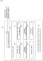
- FIG. 2 illustrates a functional configuration of the computer 50.
- FIGS. 1 and 2 a functional configuration of the computer 50 according to the present embodiment is described.
- the computer 50 includes: a data acquisition unit 51 to obtain temperature distribution data and periodic signals input from the infrared thermographic camera 40 (see FIG. 1 ); a calculation unit 52 to calculate each measurement based on the temperature distribution data and the periodic signals obtained by the data acquisition unit 51; and a calculation result output unit 59 to output calculation results to a liquid crystal display (not shown) or the like.
- the calculation unit 52 includes a phase lag distribution calculation unit 53, a temperature amplitude distribution calculation unit 54, a thermal diffusivity distribution calculation unit 55, a thermal conductivity calculation unit 56, a specific heat calculation unit 57, and a fatigue evaluation calculation unit 58.
- the phase lag distribution calculation unit 53 calculates a phase lag distribution based on the temperature distribution data and the periodic signals obtained by the data acquisition unit 51.
- the temperature amplitude distribution calculation unit 54 calculates a temperature amplitude distribution based on the temperature distribution data and the periodic signals obtained by the data acquisition unit 51.
- the thermal diffusivity distribution calculation unit 55 calculates a thermal diffusivity distribution based on the phase lag calculated by the phase lag distribution calculation unit 53.
- the thermal conductivity calculation unit 56 calculates a thermal conductivity based on the temperature amplitude distribution calculated by the temperature amplitude distribution calculation unit 54.
- the specific heat calculation unit 57 calculates specific heat based on the thermal diffusivity calculated by the thermal diffusivity distribution calculation unit 55 and the thermal conductivity calculated by the thermal conductivity calculation unit 56.
- the fatigue evaluation calculation unit 58 calculates a fatigue evaluation (described below), which is an evaluation of fatigue of the measurement sample 1 (see FIG. 1 ), based on the specific heat calculated by the specific heat calculation unit 57.
- the thermal diffusivity distribution calculation unit 55 calculates the thermal diffusivity based on equation (2) described below.
- the thermal conductivity calculation unit 56 calculates the thermal conductivity based on equation (6) described below.
- the specific heat calculation unit 57 calculates the specific heat based on equation (1) described below.
- the computer 50 of the present embodiment evaluates the measurement sample 1 (see FIG. 1 ), i.e., evaluates the thermophysical properties and fatigue (described below) of the measurement sample, based on the temperature distribution of the measurement sample 1 detected by the infrared thermographic camera 40.
- thermophysical properties as referred to herein include the thermal diffusivity, thermal conductivity, and specific heat.
- the computer 50 of the present embodiment calculates at least one of the thermal diffusivity distribution, thermal conductivity distribution, and specific heat distribution of the measurement sample 1 (see FIG. 1 ) based on the temperature distribution of the measurement sample 1 detected by the infrared thermographic camera 40.
- the thermophysical properties may also include fatigue (described below).
- a fatigue condition refers to the degree of material alteration that occurs as a result of the measurement sample 1 being continuously or repeatedly subjected to cyclic stress. Evaluation of the fatigue condition refers to evaluation of the degree of fatigue. As the fatigue progresses, crack initiation due to fatigue damage, fatigue crack propagation, breakage, etc. occur in the measurement sample 1.
- Carbon fiber-reinforced composite materials which are an example of the measurement sample 1, are expected to find applications in, for example, transportation and aerospace industries by virtue of their advantages such as high specific strength, corrosion resistance, and fatigue resistance properties.
- characteristics of carbon fiber-reinforced composite materials associated with fatigue i.e., fatigue properties
- fatigue properties vary greatly depending on the manufacturing quality and operating environment. Therefore, it is required to understand the fatigue properties of carbon fiber-reinforced composite materials.
- Such understanding of the fatigue properties is expected to, for example, extend the designed lifetime of products.
- the fatigue condition of the measurement sample 1 is calculated by measuring at least one of the macro-scale thermal diffusivity distribution, thermal conductivity, and specific heat, using non-contact laser heating.
- microcracks and micro delamination in the measurement sample 1 are accompanied by occurrence of a crack interface inside the measurement sample 1. This interface then acts as a thermal resistance, potentially resulting in local changes in the thermal diffusivity, thermal conductivity, and specific heat of the measurement sample 1.
- the presence of microcracks may be detected by measuring the in-plane thermal diffusivity, thermal conductivity, and specific heat of the measurement sample 1.
- these changes in thermal diffusivity, thermal conductivity, and specific heat are utilized to quantify the growth trend of microcracks and micro delamination with the use of laser beam, thereby allowing for diagnosis of the fatigue condition of the measurement sample 1. This may allow for quantification of the fatigue condition of the measurement sample 1 in a nondestructive and more extensive manner.
- the present embodiment enables detection of growth trends of microcracks and micro delamination that, for example, are not visually recognizable, making it possible to detect an initial degradation of the measurement sample 1. While the microcracks and micro delamination have been discussed above, material alterations that occur inside the measurement sample 1 are not limited to these. Other material alterations include, for example, lattice defects and bond breaks that occur inside the measurement sample 1. In the present embodiment, changes in thermal diffusivity, thermal conductivity, and specific heat, which are examples of the thermophysical property value, may be utilized to quantify these material alterations as well.
- the fatigue evaluation of the measurement sample 1 in the present embodiment is performed by measuring at least one of the thermal diffusivity, thermal conductivity, and specific heat, as described above.
- the specific heat in an undamaged condition is compared with that after a predetermined number of applications of loads, and the difference in specific heat, or more specifically, the amount of change in specific heat is evaluated as a function of the number of load cycles.
- the larger this evaluation function the more fatigue has progressed, i.e., the more pronounced the fatigue is.
- a threshold of the evaluation function may be defined in advance, and comparison with this threshold may be used to evaluate whether a predetermined fatigue condition has been reached. In other words, the fatigue condition can be diagnosed by monitoring the evaluation function.
- the specific heat distribution of the measurement sample 1 can also be measured. And a portion with different specific heat than other portions can be diagnosed as having fatigue in progress. In other words, in the present embodiment, the fatigue condition can be diagnosed by monitoring the specific heat distribution in the measurement sample 1.
- FIG. 3 illustrates an example hardware configuration of the computer 50.
- the computer 50 includes a central processing unit (CPU) 501 as an arithmetic means, and a main memory 503 and a hard disk drive (HDD) 505 as storage means.
- the CPU 501 executes various programs such as an operating system (OS) and application software.
- the main memory 503 is a storage area for storing various programs and data used in the execution of the programs, etc.
- the HDD 505 is a storage area for storing input data for various programs and output data from various programs, etc.
- the computer 50 includes a communication interface (communication I/F) 507 for communication with external devices such as the infrared thermographic camera 40.
- the programs to be executed by the CPU 501 may be stored in the main memory 503 in advance, may be stored in a storage medium such as a CD-ROM and provided to the CPU 501, or may be provided to the CPU 501 via a network (not shown).
- thermophysical properties in the first embodiment are now described.
- the specific heat Cp is calculated based on the above equation (1).
- the thermal conductivity k is measured by the thermophysical property evaluation device 100, which employs a lock-in thermography periodic heating method.
- the thermal diffusivity D is also measured by the thermophysical property evaluation device 100.
- the density ⁇ is also measured by any well-known technique, such as the Archimedes method.
- the specific heat Cp is calculated based on the above equation (1).
- thermophysical property evaluation device 100 When the density ⁇ is not measured, the thermal conductivity k and the thermal diffusivity D are measured by the thermophysical property evaluation device 100, and a volumetric specific heat capacity pCp is calculated based on the above equation (1).
- thermophysical property evaluation device 100 While the following discusses measuring the thermal diffusivity D using the lock-in thermographic periodic heating method via the thermophysical property evaluation device 100, the measurement method is not limited to this. Any well-known measurement method capable of measuring the thermal diffusivity D may be employed.
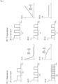
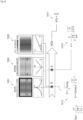
- FIGS. 4(A) and 4(B) illustrate the principles of measuring thermophysical properties in the first embodiment, where FIG. 4(A) illustrates the principle of measuring a thermal diffusivity, and FIG. 4(B) illustrates the principle of measuring a thermal conductivity.
- the thermal diffusivity is measured using the thermophysical property evaluation device 100. Specifically, a frequency dependence of the temperature amplitude (see FIG. 4 (A-4)) and a frequency dependence of the phase lag (see FIG. 4 (A-4)) are measured by periodically heating the measurement sample 1 with the laser beam emitted from the diode laser 10 while varying its frequency but keeping its power constant as shown in FIGS. 4 (A-1) through 4(A-3). A thermal diffusivity distribution is then calculated from the measured frequency dependences of the temperature amplitude and the phase lag.
- a power dependence of the temperature amplitude (see FIG. 4 (B-4)) is measured by periodically heating the measurement sample 1 with the laser beam emitted from the diode laser 10 while varying its power but keeping its frequency constant as shown in FIGS. 4 (B-1) through 4(B-3).
- a thermal conductivity distribution is then calculated from the measured power dependence of the temperature amplitude.
- the thermal conductivity distribution is determined from the relationship between the temperature amplitude decay and the laser power.
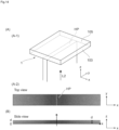
- FIGS. 5(A) and 5(B) illustrate a model of the measurement principles in the first embodiment, where the figures depict heating conditions.
- the generally planar measurement sample 1 has a thickness d.
- This measurement sample 1 has a thermal conductivity k and a thermal diffusivity D.
- One side of the measurement sample 1, or the first surface 103, is uniformly and periodically heated by a laser beam L1 at an angular frequency ⁇ .
- the first surface 103 in this example is subjected to area heating by the laser beam L1.
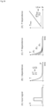
- FIG. 6 illustrates the principle of measuring a specific heat capacity in the first embodiment.
- a through-plane thermal diffusivity D is obtained by measuring the temperature amplitude (see reference numeral 601) and the phase lag (see reference numeral 603) while varying the frequency and then fitting the temperature amplitude of the above equation (4) and the phase lag of the above equation (5) to the obtained curves (see reference numerals 607, 613 in the figure).
- a through-plane thermal conductivity k is obtained from the linear slope of laser power dependence of the temperature amplitude (see reference numerals 609, 615), which is obtained by measuring the temperature amplitude (see reference numeral 605) while varying the laser power but keeping the frequency constant.
- a distribution of the through-plane thermal conductivity k is output as an image (see reference numeral 609 in the figure).
- a specific heat capacity pCp is calculated from the above through-plane thermal diffusivity D and through-plane thermal conductivity k based on the above equation (1) (see reference numerals 611, 617). To further illustrate, in the present embodiment, a distribution of the specific heat capacity pCp is output as an image (see reference numeral 611).
- FIG.7 is a flowchart of a fatigue evaluation and determination operation by the thermophysical property evaluation device 100 (see FIG. 1 ).
- thermophysical property evaluation device 100 a fatigue evaluation operation by the thermophysical property evaluation device 100 of the present embodiment is described.
- a tensile load is repeatedly applied to the measurement sample 1 by a tensile tester (not shown).
- the thermophysical property evaluation device 100 performs the fatigue evaluation operation.
- the fatigue evaluation operation is performed in response to the number of load cycles reaching 1,000, 10,000, and 100,000. It is assumed that the fatigue condition of the measurement sample 1 in an undamaged condition, i.e., at zero load cycles, has already been measured.
- thermophysical property evaluation device 100 performs the fatigue evaluation (S702).
- the fatigue evaluation calculation unit 58 determines whether to terminate the tensile test, i.e., whether the number of load cycles has reached a set value (S703). If the tensile test is to be terminated (YES in S703), the calculation result output unit 59 outputs the calculation results for the measurement sample 1 to a display area (not shown) such as an LCD display (S704). On the other hand, if the tensile test is not to be terminated (NO in S703), the tensile test is performed by the tensile tester (S701).
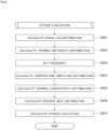
- FIG.8 is a flowchart of a fatigue evaluation process by the thermophysical property evaluation device 100 (see FIG. 1 ).
- thermophysical property evaluation device 100 in the present embodiment is described.
- the phase lag distribution calculation unit 53 calculates the phase lag distribution (S801). Specifically, the measurement sample 1 is periodically heated by the laser beam emitted from the diode laser 10. The phase lag distribution calculation unit 53 obtains the temperature distribution via the infrared thermographic camera 40 while varying the frequency of the laser beam emitted from the diode laser 10, and calculates the phase lag distribution. Based on the calculated phase lag distribution, the thermal diffusivity distribution calculation unit 55 calculates the thermal diffusivity distribution (S802).
- the temperature amplitude distribution calculation unit 54 sets the frequency to be used in measuring the temperature amplitude distribution (S803).
- the temperature amplitude distribution calculation unit 54 then calculates the temperature amplitude distribution (S804). Specifically, the measurement sample 1 is periodically heated by the laser beam emitted from the diode laser 10. The temperature amplitude distribution calculation unit 54 obtains the temperature distribution via the infrared thermographic camera 40 while varying the laser power of the laser beam emitted from the diode laser 10, and calculates the temperature amplitude distribution. Based on the calculated temperature amplitude distribution, the thermal conductivity calculation unit 56 calculates the thermal conductivity distribution (S805).
- the specific heat calculation unit 57 calculates the specific heat distribution (S806). Based on the calculated specific heat distribution, the fatigue evaluation calculation unit 58 calculates the fatigue evaluation of the measurement sample 1 (S807).
- the phase lag distribution calculation unit 53 calculates the phase lag distribution prior to the temperature amplitude measurement by the temperature amplitude distribution calculation unit 54. Then, within the range of frequencies set by the phase lag distribution calculation unit 53, the frequencies for the temperature amplitude measurement are set (S803). This enables a more efficient temperature amplitude measurement by the temperature amplitude distribution calculation unit 54.
- the order of performance of the phase lag measurement by the phase lag distribution calculation unit 53 and the temperature amplitude measurement by the temperature amplitude distribution calculation unit 54 is not limited.
- the temperature amplitude distribution calculation unit 54 may measure the temperature amplitude prior to the phase lag measurement by the phase lag distribution calculation unit 53.
- FIGS. 9(A) through 9(E) illustrate first measurement results. Specifically, FIG. 9(A) illustrates a first sample 101, which is an example of the measurement sample 1.
- FIG. 9(B) illustrates a distribution of laser power dependence of the temperature amplitude.
- FIG. 9(C) illustrates a thermal conductivity distribution.
- FIG. 9(D) illustrates a thermal diffusivity distribution.
- FIG. 9(E) illustrates a volumetric specific heat distribution.
- This first sample 101 is a 36 mm wide, 120 mm long, and 1 mm thick composite material, specifically a carbon fiber-reinforced resin.
- the region of observation in the first sample 101 is 36 mm wide and 45 mm long.
- the frequency of the laser used for the phase lag distribution calculation (first measurement; see S801 in FIG. 8 above) is varied in units of 0.02 Hz from 0.3 to 0.54 Hz.
- This laser has a laser power of 1750 mW.
- the laser power of the laser used for the temperature amplitude distribution calculation (second measurement; see S804 in FIG. 8 above) is varied in units of 250 mW from 500 to 2000 mW.
- This laser has a frequency of 0.125 Hz.
- varying the laser power means switching the maximum output for one period of the laser beam with which the periodic heating is performed. In other words, varying the laser power means switching the maximum output of the laser beam at least between a first maximum output and a second maximum output. In still other words, varying the laser power means varying the irradiation amplitude of the laser beam.
- FIGS. 9(B) through 9(E) the distribution of laser power dependence of the temperature amplitude, the thermal conductivity distribution, the thermal diffusivity distribution, and the volumetric specific heat distribution of the first sample 101 were calculated. This indicates that the specific heat of the first sample 101 can be measured in a nondestructive and non-contact manner.
- FIGS. 10(B) through 10(E) indicate that the specific heat distribution of the first sample 101 can be detected by the thermophysical property evaluation device 100 (see FIG. 1 ).
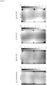
- FIGS. 10(A) through 10(D) illustrate second measurement results. Specifically, FIGS. 10(A) through 10(D) illustrate results of evaluation of the progress of fatigue degradation with increased number of load cycles, as evaluated based on specific heat. To further illustrate, FIG. 10(A) illustrates a volumetric specific heat distribution of the above first sample 101 (see FIG. 9 ) in an undamaged condition, i.e., at zero load cycles (N). Similarly, FIGS. 10(B), 10(C), and 10(D) illustrate volumetric specific heat distributions at 10 3 , 10 4 , and 10 5 load cycles, respectively. As shown in FIGS. 10(A) through 10(D) , the volumetric specific heat distribution of the first sample 101 was found to vary with an increase in the number of load cycles.
- FIGS. 11(A) through 11(E) illustrate the second measurement results. Specifically, FIGS. 11(A) through 11(D) illustrate changes in specific heat calculated from the specific heat distributions respectively shown in FIGS. 10(A) through 10(D) above. More specifically, the horizontal and vertical axes in FIGS. 11(A) through 11(D) represent the volumetric specific heat and the count, respectively. FIG. 11(E) illustrates changes in specific heat capacity as a function of the number of load cycles.
- FIGS. 11(A) through 11(D) the specific heat was observed to vary with an increase in the number of load cycles. Also, as shown in FIG. 11(E) , the specific heat, or entropy, was observed to tend to increase with an increase in the number of load cycles. More specifically, FIGS. 11(A) through 11(E) indicate that the progress of fatigue degradation of the first sample 101 can be measured by the thermophysical property evaluation device 100 (see FIG. 1 ) based on specific heat.
- thermophysical property evaluation device 100 can measure the thermal conductivity in a nondestructive and non-contact manner.
- the thermophysical property evaluation device 100 can measure in-situ the thermal conductivity of a measurement sample 1 that has already been finished as a product.
- the thermophysical property evaluation device 100 can measure the thermal conductivity of even a rare measurement sample 1 in a nondestructive manner.
- DSC differential scanning calorimetry
- the DSC method requires destructive testing, i.e., cutting and crushing of samples, and possible structural changes during crushing processes may cause measurements to vary.
- the DSC method requires a reference material whose specific heat value is known.
- the DSC method can obtain an average specific heat value of a sample, it is difficult for this method to measure its specific heat distribution.
- thermophysical property evaluation device 100 can measure in-situ the specific heat in a nondestructive and non-contact manner.
- the thermophysical property evaluation device 100 can do without reference materials for specific heat measurement, improving the reliability of the measurement.
- the thermophysical property evaluation device 100 can measure a specific heat distribution, so that it can detect areas with different physical properties in the measurement sample 1 (i.e., can detect damages).
- FIG. 12 illustrates a schematic configuration of a thermophysical property evaluation device 200 according to a second embodiment.
- thermophysical property evaluation device 200 Referring now to FIG. 12 , a configuration of the thermophysical property evaluation device 200 according to the second embodiment is described. Similar components to those in the above embodiment are hereinafter identified by the same reference numerals, and detailed descriptions thereof may be omitted.
- line heating may be performed on the first surface 103 of the measurement sample 1, as in the thermophysical property evaluation device 200 shown in FIG. 12 .
- the thermophysical property evaluation device 200 includes a diode laser 110 serving as a light source for heating the measurement sample 1, a light guide 210 for directing a laser beam of the diode laser 110 to the measurement sample 1, and a holder 310 for holding the measurement sample 1.
- the diode laser 110 heats a portion (heating region Hp) of the measurement sample 1 that extends in one direction on the surface thereof.
- the diode laser 110 is a light source for line heating.
- the light guide 210 includes a mirror 211 to reflect a laser beam emitted from the diode laser 110, a beam expander 213 to expand the beam diameter of the laser beam from the mirror 211, and a cylindrical lens 215 to shape the laser beam from the beam expander 213 into sheet light.
- the laser beam emitted from the diode laser 110 is incident on the measurement sample 1 through the mirror 211, the beam expander 213, and the cylindrical lens 215.
- the laser beam emitted from the diode laser 110 is incident in a direction perpendicular to the first surface 103 of the measurement sample 1.
- the region irradiated with the laser beam region extending in one direction
- a specific region (heating region Hp) in the first surface 103 of the measurement sample 1, or a spot is periodically heated.
- the computer 50 in combination with the infrared thermographic camera 40, continuously captures infrared images and performs computations at predetermined frame rate intervals to create an averaged image based on the amount of temperature change over time (lock-in method).
- the data obtained from the infrared thermographic camera 40 is processed by the computer 50 to calculate an in-plane thermal conductivity of the measurement sample 1.
- the data obtained from the infrared thermographic camera 40 is also processed by the computer 50 to calculate information about thermophysical properties of the measurement sample 1.
- thermophysical property evaluation device 100 in the above first embodiment uses the diode laser 10 and the light guide 20 to emit light with a uniform intensity distribution onto the surface of the measurement sample 1.
- thermophysical property evaluation device 200 does not require an arrangement to homogenize the light.
- FIGS. 13(A) and 13(B) illustrate the principles of measuring thermophysical properties in the second embodiment, where FIG. 13(A) illustrates the principle of measuring a thermal diffusivity, and FIG. 13(B) illustrates the principle of measuring a thermal conductivity.
- the measurement principles in the second embodiment are now outlined with reference to FIGS. 13(A) and 13(B) .
- a thermal diffusivity is measured using the thermophysical property evaluation device 200. Specifically, a distance dependence of the temperature amplitude (see FIGS. 13 (A-2) and 13(A-3)) and a distance dependence of the phase lag (see FIGS. 13 (A-4) and 13(A-5)) are measured by periodically heating the measurement sample 1 with the laser beam emitted from the diode laser 10 while keeping its power and frequency constant as shown in FIG. 13 (A-1). A thermal diffusivity distribution is then calculated from the measured distance dependences of the temperature amplitude and the phase lag.
- a power dependence of the temperature amplitude (see FIG. 13 (B-4)) is measured by periodically heating the measurement sample 1 with the laser beam emitted from the diode laser 10 while varying its power but keeping its frequency constant as shown in FIGS. 13 (B-1) through 13(B-3).
- a thermal conductivity distribution is then calculated from the measured power dependence of the temperature amplitude.
- the thermal conductivity distribution is determined from the relationship between the temperature amplitude decay and the laser power.
- FIGS. 14(A) and 14(B) illustrate a model of the measurement principles in the second embodiment, where the figures depict heating conditions.
- the generally planar measurement sample 1 has a thickness d.
- the measurement sample 1 shall be a thermally thin object.
- This measurement sample 1 has a thermal conductivity k and a thermal diffusivity D.
- One side of the measurement sample 1, or the first surface 103 is uniformly and periodically heated by a laser beam L2 at an angular frequency ⁇ .
- the first surface 103 in this example is subjected to line heating by the laser beam L2.
- FIG. 15 illustrates the principle of measuring a specific heat capacity in the second embodiment.
- an in-plane thermal diffusivity D is obtained by measuring the distance dependence of the temperature amplitude (see reference numeral 1501) and the distance dependence of the phase lag (see reference numeral 1503) and then fitting the temperature amplitude of the above equation (8) and the phase lag of the above equation (9) to the obtained curves (see reference numeral 1513 in the figure).
- An in-plane thermal conductivity k is obtained from the linear slope of laser power dependence of the temperature amplitude (see reference numeral 1515), which is obtained by measuring the temperature amplitude (see reference numeral 1505).
- FIGS. 16(A) through 16(C) illustrate third measurement results. Specifically, FIG. 16(A) illustrates the laser power dependence of the temperature amplitude. FIG. 16(B) illustrates the laser power dependence of the phase. FIG. 16(C) illustrates the laser power dependence of the temperature amplitude.
- the third measurement results are now shown with reference to FIG. 16 .
- the measurement sample 1 in this measurement is a composite material.
- the frequency of the laser used for the phase lag distribution calculation (see S801 in FIG. 8 above) is varied in units of 0.02 Hz from 0.3 to 0.54 Hz.
- This laser has a laser power of 150 mW.
- the laser power of the laser used for the temperature amplitude distribution calculation (see S804 in FIG. 8 above) is varied in units of 25 mW from 150 to 300 mW.
- This laser has a frequency of 0.05 Hz.
- thermophysical properties calculated from FIG. 16(A) through 16(C) were as follows: the in-plane thermal diffusivity was 1.06 (m 2 /s),the in-plane thermal conductivity was 1.84 (W/m ⁇ K), and the specific heat capacity was 1641.1 (kJ/m 3 K).
- FIG. 17 illustrates a schematic configuration of a thermophysical property evaluation device 300 according to a third embodiment.
- thermophysical property evaluation device 300 Referring now to FIG. 17 , a configuration of the thermophysical property evaluation device 300 according to the third embodiment is described. Similar components to those in the above embodiments are hereinafter identified by the same reference numerals, and detailed descriptions thereof may be omitted.
- a high-intensity, short-duration uniform laser beam may be emitted once, i.e., pulsed, onto the first surface 103 of the measurement sample 1, as in the thermophysical property evaluation device 300 shown in FIG. 17 .
- thermophysical property evaluation device 300 includes the diode laser 10 serving as a light source for heating the measurement sample 1, the light guide 20 for directing the laser beam of the diode laser 10 to the measurement sample 1, a holder 310 for holding the measurement sample 1, the infrared thermographic camera 40, and the computer 50.
- the thermophysical property evaluation device 300 does not include the periodic signal generator 70 (see FIG. 1 ).
- thermophysical property evaluation device 300 emits a high-intensity, short-duration uniform laser pulse once to heat the surface of the measurement sample 1.
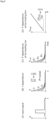
- FIGS. 18(A) through 18(D) illustrate the principles of measuring thermophysical properties in the third embodiment, where FIG. 18(A) illustrates a heating laser, FIG. 18(B) illustrates the principle of measuring a thermal diffusivity, and FIGS. 18(C) and 18(D) illustrate the principle of measuring a thermal conductivity.
- the measurement principles in the third embodiment are now outlined with reference to FIGS. 18(A) through 18(D) .
- the measurement sample 1 is heated by a pulsed laser from the diode laser 10, as shown in FIG. 18(A) .
- This heating is used to measure a time dependence of the temperature (see FIG. 13(B) ), i.e., temperature decay.
- a thermal diffusivity distribution is then calculated from the measured time dependence of the temperature.
- a power dependence of the maximum temperature is measured by heating the measurement sample 1 with the laser beam emitted from the diode laser 10 while varying its power.
- a thermal conductivity distribution is calculated from the measured power dependence of the maximum temperature.
- the thermal conductivity distribution is determined from the relationship between the maximum temperature and the laser power.
- This measurement sample 1 has a thickness d. Also, the measurement sample 1 shall have a thermal conductivity k and a thermal diffusivity D.
- One side of the measurement sample 1, or the first surface 103, is uniformly heated by the laser beam L1.
- the first surface 103 in this example is subjected to area heating by the laser beam L1.
- FIG. 19 illustrates the principle of measuring a specific heat capacity in the third embodiment.
- a through-plane thermal diffusivity D is obtained by measuring a time dependence of the temperature, i.e., exponential decay of the temperature (see reference numeral 1901), and fitting, for example, a well-known formula (see reference numeral 1913) to the obtained curve (see reference numeral 1907 in the figure).
- time t 0.5 until the temperature rise reaches 50% of its maximum value is defined as an exponential decay to calculate the thermal diffusivity D.
- a through-plane thermal conductivity k is obtained from the linear slope of laser power dependence of the maximum temperature (see reference numerals 1909, 1915 in the figure), which is obtained by measuring the maximum temperature (see reference numeral 1903) at each pixel (at each location).
- FIG. 20 illustrates a schematic configuration of a thermophysical property evaluation device 400 according to a fourth embodiment.
- thermophysical property evaluation device 400 Referring now to FIG. 20 , a configuration of the thermophysical property evaluation device 400 according to the fourth embodiment is described. Similar components to those in the above embodiments are hereinafter identified by the same reference numerals, and detailed descriptions thereof may be omitted.
- thermophysical property evaluation device 400 shown in FIG. 20 may be configured to emit a pulsed laser beam onto a region of the measurement sample 1 extending in one direction on the first surface 103 thereof.
- thermophysical property evaluation device 400 includes the diode laser 110 serving as a light source for heating the measurement sample 1, the light guide 210 for directing the laser beam of the diode laser 110 to the measurement sample 1, a holder 310 for holding the measurement sample 1, the infrared thermographic camera 40, and the computer 50.
- the thermophysical property evaluation device 400 does not include the periodic signal generator 70 (see FIG. 1 ).
- thermophysical property evaluation device 400 emits a high-intensity, short-duration uniform laser pulse once to heat the surface of the measurement sample 1.
- FIGS. 21(A) through 21(D) illustrate the principles of measuring thermophysical properties in the fourth embodiment, where FIG. 21(A) illustrates a heating laser, FIG. 21(B) illustrates the principle of measuring a thermal diffusivity, and FIGS. 21(C) and 21(D) illustrate the principle of measuring a thermal conductivity.
- the measurement principles in the fourth embodiment are now outlined with reference to FIGS. 21(A) through 21(D) .
- the measurement sample 1 is heated by a pulsed laser from the diode laser 110, as shown in FIG. 21(A) .
- This heating is used to measure a time dependence of the temperature (see FIG. 21(B) ), i.e., temperature decay.
- a thermal diffusivity distribution is then calculated from the measured time dependence of the temperature.
- a power dependence of the maximum temperature is measured by heating the measurement sample 1 with the laser beam emitted from the diode laser 110 while varying its power. Then, as shown in FIG. 21(D) , a thermal conductivity distribution is calculated from the measured power dependence of the maximum temperature. In other words, in the present embodiment, the thermal conductivity distribution is determined from the relationship between the maximum temperature and the laser power.
- This measurement sample 1 has a thickness d. Also, the measurement sample 1 shall have a thermal conductivity k and a thermal diffusivity D.
- One side of the measurement sample 1, or the first surface 103, is heated by the laser beam L2.
- the first surface 103 in this example is subjected to line heating by the laser beam L2.
- FIG. 22 illustrates the principle of measuring a specific heat capacity.
- an in-plane thermal diffusivity D is obtained by measuring a time dependence of the temperature, i.e., exponential decay of the temperature (see reference numeral 2201), and fitting, for example, a well-known formula (see reference numeral 2213) to the obtained curve.
- time t 0.5 until the temperature rise reaches 50% of its maximum value is defined as an exponential decay to calculate the thermal diffusivity D.
- C(r) is an instrument constant that depends on the measurement system. The C(r) depends on the relative distance r of the measurement point (which can be obtained from an image of the infrared thermographic camera 40) from the laser beam in the x direction.
- An in-plane thermal conductivity k is obtained from the linear slope of laser power dependence of the maximum temperature (see reference numeral 2215 in the figure), which is obtained by measuring the maximum temperature (see reference numeral 2203) at each pixel.
- FIG. 23 illustrates a measurement condition control unit 550 according to variation 1.
- thermophysical property evaluation device 100 may be configured to switch heating conditions, i.e., measurement conditions.
- the computer 50 may include a measurement condition control unit 550.
- the measurement condition control unit 550 includes a heating region switching unit 570 to switch heating regions between that for area heating and that for line heating, and a heating mode switching unit 590 to switch heating modes between periodic heating and pulsed heating.
- the heating region switching unit 570 includes an in-plane measurement unit 571 and a through-plane measurement unit 573.
- the in-plane measurement unit 571 controls an in-plane measurement mechanism 220.
- the in-plane measurement mechanism 220 performs line heating via, e.g., the light guide 210 (see FIG. 12 ).
- the through-plane measurement unit 573 controls a through-plane measurement mechanism 230.
- the through-plane measurement mechanism 230 performs area heating via, e.g., the light guide 20 (see FIG. 1 ).
- the heating mode switching unit 590 includes a periodic heating measurement unit 591 and a pulsed heating measurement unit 593.
- the periodic heating measurement unit 591 controls the diode laser 10 via the periodic signal generator 70 to perform periodic heating.
- the pulsed heating measurement unit 593 controls the diode laser 10 to perform pulsed heating.
- the measurement condition control unit 550 switches the measurement conditions through the heating region switching unit 570 and the heating mode switching unit 590.
- the first surface 103 (front side) of the measurement sample 1 is heated by the diode laser 10 and the second surface 105 (back side) of the measurement sample 1 is measured by the infrared thermographic camera 40.
- this is not limiting.
- the heating of the measurement sample 1 by the diode laser 10 and the measurement of the measurement sample 1 by the infrared thermographic camera 40 may be performed on the same side of the measurement sample 1.
- the diode laser 10 and the light guide 20 are used to heat the measurement sample 1.
- any other method or arrangement may be used that ensure a uniform intensity distribution on the irradiation plane of the measurement sample 1.
- an array of multiple light emitting diodes (LEDs) may be used as the light source.
- Other heating methods that can heat the entire measurement sample 1, such as induction heating or resistance heating, may be used.
- a diffuser plate such as so-called frosted glass, may be used to diffuse light from the light source.
- a diode laser with a relatively large Gaussian distribution may be used as the diode laser 10.
- a constant light intensity portion of the laser beam with a relatively large Gaussian distribution may be used to homogenize the intensity distribution on the irradiation plane of the measurement sample 1.
- the diaphragm 33 is provided between the measurement sample 1 and the infrared thermographic camera 40.
- an implementation without the diaphragm 33 is also possible.
- the laser beam emitted from the diode laser 10 to the cylindrical lens 215 is perpendicular to the first surface 103 of the measurement sample 1.
- this is not limiting. That is, the laser beam from the diode laser 10 may be emitted obliquely, provided that the heating region Hp is elongate in one direction on the first surface 103 of the measurement sample 1.
- the cylindrical lens 215 is used to make the heating region Hp elongate in one direction.
- a masking member may be provided to block a portion of the laser beam to make the heating region Hp elongate in one direction.
- a sheet laser that emits sheet light may be used as a light source instead of the diode laser 10.
- the laser beam may be emitted obliquely with respect to the top surface 11 of the measurement sample 1 to make the heating region Hp elongate in one direction.
- the means for heating the measurement sample 1 by the diode laser 10 is not limited to laser beams. Other heating methods that can locally heat the measurement sample 1, such as induction heating or resistance heating, may also be used.
- the measurement sample 1 is not limited. For example, glass, synthetic diamonds, semiconductors, polymer films, liquid crystal, etc. may be used as the measurement sample 1.
- the inventive techniques discussed herein can detect voids or cracks formed inside the measurement sample 1.
- the inventive techniques can obtain information about the density of the measurement sample 1 as an evaluation of the measurement sample 1.
- the information about the density refers to information that can be used to determine the density of the measurement sample 1.
- the information about the density includes, in addition to the value of the density of the measurement sample 1, a relative evaluation of the density (e.g., coarse/dense) and the presence/absence of voids inside the measurement sample 1.
- carbon fiber-reinforced resin has been used as the measurement sample 1.
- the type of this carbon fiber-reinforced resin is not limited and may be, for example, a recycled carbon fiber reinforced resin.
- the measurement sample 1 may be an uncured carbon fiber-reinforced resin prior to molding (curing) by heating/pressurizing, i.e., an intermediate base material.
- the measurement sample 1 may be composed of multiple types of materials with mutually different thermal conductivities.
- the measurement sample 1 may be any material other than composite materials.
- the measurement sample 1 may be a glass, semiconductor, polymer film, liquid crystal, or the like.
- Products in actual use may also be used as the measurement sample 1.
- the above measurement of specific heat and other metrics can be performed on relevant portions of building structures (e.g., suspension ropes of bridge piers) to detect the condition of the portions.
- the above measurement of specific heat and other metrics can be performed on relevant portions of machinery (e.g., turbines), structures such as yachts, rockets, etc., or residential structures such as window sashes (fittings) to detect the condition of the portions.
- differences in thermal conductivity and specific heat from those in the reference undamaged condition is used for the fatigue evaluation.
- this is not limiting.
- a ratio between specific heat rates or an absolute value of specific heat may be used for the fatigue evaluation.
- fatigue evaluation may be performed based on the condition where the fatigue life has been reached or on prior evaluation data or theoretical values.
- the information about the fatigue includes, in addition to values calculated as fatigue evaluations of the measurement sample 1, relative evaluation of fatigue (e.g., how far fatigue has progressed), reaching or not reaching the fatigue life, the estimated duration and number of times the sample can be used before reaching the fatigue life, the presence or absence of microcracks or micro delamination inside the measurement sample 1, etc.
- the information about the thermal diffusivity, about the thermal conductivity, and about the specific heat which is obtained in the process of calculating the information about the fatigue of the measurement sample 1, may be output and/or stored together with or instead of the information about the fatigue.
- the information about the thermal diffusivity, about the thermal conductivity, and about the specific heat includes, but is not limited to, the thermal conductivity distribution, values of the thermal conductivity and other metrics (including average, maximum, and minimum values), relative evaluations of the thermal conductivity and other metrics (e.g., how large or small the thermal diffusivity is), and results of comparison with prior evaluation data or theoretical values.
- information about the life of the measurement sample 1 may be output and/or stored together with or instead of the information about the fatigue of the measurement sample 1.
- the information about the life includes reaching or not reaching the fatigue life, the estimated duration and number of times the sample can be used before reaching the fatigue life, and the degree (e.g., percentage) of fatigue progress with respect to the fatigue life, etc.
- the information about the fatigue of the measurement sample 1 may be obtained from any other load test that applies loads to the measurement sample 1, such as plane bending fatigue tests, rotary bending fatigue tests, and ultrasonic fatigue tests.
- the tensile tester (not shown) may or may not be included in the thermophysical property evaluation device 100.
- the calculation result display unit 59 displays (outputs), on the display (not shown), the calculation results of the thermal conductivity, specific heat, and other metrics as evaluations of the sample.
- the calculation results of at least one of the thermal diffusivity, thermal conductivity, and specific heat may be transmitted to other devices than the computer 50 or may be stored in the computer 50.
- a program of the above measurement method may be stored in a well-known thermophysical property measurement device (not shown).
- the above measurement method may be provided over a network (not shown).
- the measurement sample 1 is an example of the object.
- the diode laser 10 is an example of the irradiation unit.
- the temperature amplitude distribution calculation unit 54 is an example of the output power switching unit, the first temperature distribution acquisition unit, and the second temperature distribution acquisition unit.
- the thermal conductivity calculation unit 56 is an example of the identification unit.
- the thermal diffusivity distribution calculation unit 55 is an example of the thermal diffusivity identification unit.
- the specific heat calculation unit 57 is an example of the specific heat identification unit and the identification unit.
- the fatigue evaluation calculation unit 58 is an example of the fatigue information identification unit and the identification unit.
Landscapes
- Physics & Mathematics (AREA)
- General Physics & Mathematics (AREA)
- Health & Medical Sciences (AREA)
- Life Sciences & Earth Sciences (AREA)
- Chemical & Material Sciences (AREA)
- General Health & Medical Sciences (AREA)
- Biochemistry (AREA)
- Analytical Chemistry (AREA)
- Immunology (AREA)
- Pathology (AREA)
- Spectroscopy & Molecular Physics (AREA)
- Engineering & Computer Science (AREA)
- Food Science & Technology (AREA)
- Medicinal Chemistry (AREA)
- Investigating Or Analyzing Materials Using Thermal Means (AREA)
Abstract
Description
- The present invention relates to a device, a method, and a program.
-
Patent Document 1 discloses a thermal conductivity measurement device including a refrigerant storage tank surrounding a test specimen. The device is configured to cool the test specimen with refrigerant introduced into the refrigerant storage tank to measure thermal conductivity of the test specimen at a temperature at or below room temperature. The device accurately measures the thermal conductivity of the test specimen by filling the refrigerant storage tank with a porous body in which the refrigerant can be dispersed and by homogenizing the temperature of the test specimen in the refrigerant storage tank by means of the refrigerant dispersed in the porous body. - Patent Document 1:
Japanese Patent Application Laid-Open Publication No. 2002-90322 - A need has existed for the ability to identify information about thermal conductivity of a measurement object in a non-contact manner in order to, for example, determine the quality of products in manufacturing processes.
- The techniques disclosed herein aim to identify information about thermal conductivity of a measurement object using a novel approach.
- With the above object in view, the techniques disclosed herein relate to a device including: an irradiation unit configured to periodically irradiate an object with light to heat the object; an output power switching unit configured to switch an output power of the light with which the object is irradiated by the irradiation unit at least between a first output power and a second output power, the first output power providing a first maximum output power during one period, the second output power providing a second maximum output power during one period; a first temperature distribution acquisition unit configured to obtain a first temperature distribution of the object, the first temperature distribution being a temperature distribution of the object heated by the light of the first output power; a second temperature distribution acquisition unit configured to obtain a second temperature distribution of the object, the second temperature distribution being a temperature distribution of the object heated by the light of the second output power; and an identification unit configured to identify information about thermal conductivity of the object based on the first temperature distribution and the second temperature distribution.
- The identification unit may be configured to: obtain a first temperature amplitude distribution of the object based on the first temperature distribution, the first temperature amplitude distribution being a temperature amplitude distribution of the object heated by the light of the first output power; obtain a second temperature amplitude distribution of the object based on the second temperature distribution, the second temperature amplitude distribution being a temperature amplitude distribution of the object heated by the light of the second output power; and identify the information about thermal conductivity of the object based on the first temperature amplitude distribution and the second temperature amplitude distribution.
- The identification unit may be configured to: obtain a first maximum temperature distribution of the object based on the first temperature distribution, the first maximum temperature distribution being a distribution of maximum temperatures at respective locations on the object heated by the light of the first output power; obtain a second maximum temperature distribution of the object based on the second temperature distribution, the second maximum temperature distribution being a distribution of maximum temperatures at respective locations on the object heated by the light of the second output power; and identify the information about thermal conductivity of the object based on the first maximum temperature distribution and the second maximum temperature distribution.
- The device may further include a thermal diffusivity identification unit configured to identify information about thermal diffusivity of the object based on responses of changes over time in the temperature distribution of the object heated by the light of the first output power.
- The device may further include a specific heat identification unit configured to identify information about specific heat of the object based on the information about thermal conductivity of the object identified by the identification unit.
- The device may further include a fatigue information identification unit configured to identify information about fatigue of the object based on the information about thermal conductivity of the object identified by the identification unit.
- The irradiation unit may be configured to irradiate the object over a wider range than a region of the object in which the temperature distribution is measured, and the identification unit may be configured to identify information about through-plane thermal conductivity of the object.
- The irradiation unit may be configured to irradiate a region of the object extending in one direction on a surface of the object, and the identification unit may be configured to identify information about in-plane thermal conductivity of the object.
- The irradiation unit may be configured to switch between a first mode and a second mode, the first mode being a mode in which the irradiation unit irradiates the object over a wider range than a region of the object in which the temperature distribution is measured, the second mode being a mode in which the irradiation unit irradiates a region of the object extending in one direction on a surface of the object, and the identification unit may be configured to identify information about through-plane thermal conductivity of the object in the first mode and to identify information about in-plane thermal conductivity of the object in the second mode.
- From another standpoint, the techniques disclosed herein relate to a method including: periodically irradiating an object with light to heat the object; switching an output power of the light with which the object is irradiated at least between a first output power and a second output power, the first output power providing a first maximum output power during one period, the second output power providing a second maximum output power during one period; obtaining a first temperature distribution of the object, the first temperature distribution being a temperature distribution of the object heated by the light of the first output power; obtaining a second temperature distribution of the object, the second temperature distribution being a temperature distribution of the object heated by the light of the second output power; and identifying information about thermal conductivity of the object based on the first temperature distribution and the second temperature distribution.
- From still another standpoint, the techniques disclosed herein relate to a program for causing a computer to execute functions of: periodically irradiating an object with light to heat the object; switching an output power of the light with which the object is irradiated at least between a first output power and a second output power, the first output power providing a first maximum output power during one period, the second output power providing a second maximum output power during one period; obtaining a first temperature distribution of the object, the first temperature distribution being a temperature distribution of the object heated by the light of the first output power; obtaining a second temperature distribution of the object, the second temperature distribution being a temperature distribution of the object heated by the light of the second output power; and identifying information about thermal conductivity of the object based on the first temperature distribution and the second temperature distribution.
- From still another standpoint, the techniques disclosed herein relate to a device including: an irradiation unit configured to periodically irradiate an object with light to heat the object; an output power switching unit configured to switch an output power of the light with which the object is irradiated by the irradiation unit at least between a first output power and a second output power, the first output power providing a first maximum output power during one period, the second output power providing a second maximum output power during one period; a first temperature distribution acquisition unit configured to obtain a first temperature distribution of the object, the first temperature distribution being a temperature distribution of the object heated by the light of the first output power; a second temperature distribution acquisition unit configured to obtain a second temperature distribution of the object, the second temperature distribution being a temperature distribution of the object heated by the light of the second output power; and an identification unit configured to identify information about specific heat of the object based on the first temperature distribution and the second temperature distribution.
- From still another standpoint, the techniques disclosed herein relate to a method including: periodically irradiating an object with light to heat the object; switching an output power of the light with which the object is irradiated at least between a first output power and a second output power, the first output power providing a first maximum output power during one period, the second output power providing a second maximum output power during one period; obtaining a first temperature distribution of the object, the first temperature distribution being a temperature distribution of the object heated by the light of the first output power; obtaining a second temperature distribution of the object, the second temperature distribution being a temperature distribution of the object heated by the light of the second output power; and identifying information about specific heat of the object based on the first temperature distribution and the second temperature distribution.
- From still another standpoint, the techniques disclosed herein relate to a program for causing a computer to execute functions of: periodically irradiating an object with light to heat the object; switching an output power of the light with which the object is irradiated at least between a first output power and a second output power, the first output power providing a first maximum output power during one period, the second output power providing a second maximum output power during one period; obtaining a first temperature distribution of the object, the first temperature distribution being a temperature distribution of the object heated by the light of the first output power; obtaining a second temperature distribution of the object, the second temperature distribution being a temperature distribution of the object heated by the light of the second output power; and identifying information about specific heat of the object based on the first temperature distribution and the second temperature distribution.
- From still another standpoint, the techniques disclosed herein relate to a device including: an irradiation unit configured to periodically irradiate an object with light to heat the object; an output power switching unit configured to switch an output power of the light with which the object is irradiated by the irradiation unit at least between a first output power and a second output power, the first output power providing a first maximum output power during one period, the second output power providing a second maximum output power during one period; a first temperature distribution acquisition unit configured to obtain a first temperature distribution of the object, the first temperature distribution being a temperature distribution of the object heated by the light of the first output power; a second temperature distribution acquisition unit configured to obtain a second temperature distribution of the object, the second temperature distribution being a temperature distribution of the object heated by the light of the second output power; and an identification unit configured to, based on the first temperature distribution and the second temperature distribution, calculate thermal conductivity of the object to identify information about fatigue of the object.
- From still another standpoint, the techniques disclosed herein relate to a method including: periodically irradiating an object with light to heat the object; switching an output power of the light with which the object is irradiated at least between a first output power and a second output power, the first output power providing a first maximum output power during one period, the second output power providing a second maximum output power during one period; obtaining a first temperature distribution of the object, the first temperature distribution being a temperature distribution of the object heated by the light of the first output power; obtaining a second temperature distribution of the object, the second temperature distribution being a temperature distribution of the object heated by the light of the second output power; and based on the first temperature distribution and the second temperature distribution, calculating thermal conductivity of the object to identify information about fatigue of the object.
- From still another standpoint, the techniques disclosed herein relate to a program for causing a computer to execute functions of: periodically irradiating an object with light to heat the object; switching an output power of the light with which the object is irradiated at least between a first output power and a second output power, the first output power providing a first maximum output power during one period, the second output power providing a second maximum output power during one period; obtaining a first temperature distribution of the object, the first temperature distribution being a temperature distribution of the object heated by the light of the first output power; obtaining a second temperature distribution of the object, the second temperature distribution being a temperature distribution of the object heated by the light of the second output power; and based on the first temperature distribution and the second temperature distribution, calculating thermal conductivity of the object to identify information about fatigue of the object.
- The techniques disclosed herein can identify information about thermal conductivity of a measurement object using a novel approach.
-
-
FIG. 1 illustrates a schematic configuration of a thermophysical property evaluation device according to a first embodiment. -
FIG. 2 illustrates a functional configuration of a computer. -
FIG. 3 illustrates an example hardware configuration of the computer. -
FIGS. 4(A) and 4(B) illustrate the principles of measuring thermophysical properties in the first embodiment. -
FIGS. 5(A) and 5(B) illustrate a model of the measurement principles in the first embodiment. -
FIG. 6 illustrates the principle of measuring a specific heat capacity in the first embodiment. -
FIG.7 is a flowchart of a fatigue evaluation and determination operation by the thermophysical property evaluation device. -
FIG.8 is a flowchart of a fatigue evaluation process by the thermophysical property evaluation device. -
FIGS. 9(A) through 9(E) illustrate first measurement results. -
FIGS. 10(A) through 10(D) illustrate second measurement results. -
FIGS. 11(A) through 11(E) illustrate the second measurement results. -
FIG. 12 illustrates a schematic configuration of a thermophysical property evaluation device according to a second embodiment. -
FIGS. 13(A) and 13(B) illustrate the principles of measuring thermophysical properties in the second embodiment. -
FIGS. 14(A) and 14(B) illustrate a model of the measurement principles in the second embodiment. -
FIG. 15 illustrates the principle of measuring a specific heat capacity in the second embodiment. -
FIGS. 16(A) through 16(C) illustrate third measurement results. -
FIG. 17 illustrates a schematic configuration of a thermophysical property evaluation device according to a third embodiment. -
FIGS. 18(A) through 18(D) illustrate the principles of measuring thermophysical properties in the third embodiment. -
FIG. 19 illustrates the principle of measuring a specific heat capacity in the third embodiment. -
FIG. 20 illustrates a schematic configuration of a thermophysical property evaluation device according to a fourth embodiment. -
FIGS. 21(A) through 21(D) illustrate the principles of measuring thermophysical properties in the fourth embodiment. -
FIG. 22 illustrates the principle of measuring a specific heat capacity. -
FIG. 23 illustrates a measurement condition control unit according tovariation 1. - Exemplary embodiments are described below with reference to the appended drawings.
-
FIG. 1 illustrates a schematic configuration of a thermophysicalproperty evaluation device 100 according to a first embodiment. - Referring to
FIG. 1 , a configuration of the thermophysicalproperty evaluation device 100 according to the present embodiment is first described below. - As shown in
FIG. 1 , the thermophysicalproperty evaluation device 100 according to the present embodiment includes adiode laser 10 serving as a light source for heating asample 1 to be measured (hereinafter the "measurement sample 1"), alight guide 20 for directing a laser beam of thediode laser 10 to themeasurement sample 1, asupport 30 for supporting themeasurement sample 1, an infrared thermographic camera (lock-in thermographic camera) 40 located opposite themeasurement sample 1, acomputer 50 for receiving signals from the infraredthermographic camera 40, and aperiodic signal generator 70 for generating periodic signals and outputting them to thediode laser 10 and thecomputer 50. - The
diode laser 10 and thelight guide 20 irradiate a surface of theplanar measurement sample 1 with light having a uniform intensity distribution. Thediode laser 10 is an area heating light source. Thediode laser 10 outputs a so-called multimode diode laser beam (e.g., TEM01) whose transverse mode is not a single mode (TEM00). - The
light guide 20 includes afiber 21 as a transmission path for the laser beam emitted from thediode laser 10, acondenser 23 located at the distal end of thefiber 21 to control the intensity distribution of the laser beam emitted from thefiber 21, and amirror 25 for reflecting the laser beam emitted from thecondenser 23. - The
fiber 21 is composed of a multimode fiber capable of propagating laser beams of different spatial modes in a mixed manner. Inside thisfiber 21, the incident angle of the laser beam emitted from thediode laser 10 is controlled to split the laser beam into meridional and skew rays. The laser beam emitted from thediode laser 10 repeatedly undergoes multiple reflections inside thefiber 21, resulting in a uniform intensity distribution on the irradiation plane. Thefiber 21 in the illustrated example has a core diameter of 100 µm and a length of 3 m. - The
condenser 23 is composed of a plurality of lenses or the like and serves as a variable focus condenser optic. Thecondenser 23 focuses (or diffuses) the laser beam emitted from thefiber 21. The laser beam emitted from thecondenser 23 propagates through the space while spreading. Thus, thecondenser 23 can be viewed as a beam expander that expands the beam diameter of the laser beam emitted from thefiber 21. - The
mirror 25 is composed of a well-known optical mirror, such as a glass substrate coated with a thin metal or dielectric film. Themirror 25 reflects the laser beam emitted from thecondenser 23 toward themeasurement sample 1. - In the thermophysical
property evaluation device 100 configured as above, the laser beam emitted from thediode laser 10 is incident on afirst surface 103 of themeasurement sample 1 through thefiber 21, thecondenser 23, and themirror 25. Themeasurement sample 1 is periodically heated by the laser beam. As shown inFIG. 1(B) , the laser beam going through thefiber 21, thecondenser 23, and themirror 25 is controlled such that the intensity distribution on the irradiation plane is homogenized into a so-called top-hat type intensity distribution. - The temperature of the
measurement sample 1, which is periodically heated by the laser beam from thediode laser 10, is measured by the infraredthermographic camera 40 at asecond surface 105 of themeasurement sample 1. The infraredthermographic camera 40 receives periodic signals input from theperiodic signal generator 70. The temperature distribution data, which is the data of the temperatures measured by the infraredthermographic camera 40, is output to thecomputer 50. The infraredthermographic camera 40 captures (measures) a predetermined area in the region periodically heated by thediode laser 10 as an infrared image. In other words, thediode laser 10 irradiates, with the laser beam, the entire portion of themeasurement sample 1 corresponding to the region observed by the infraredthermographic camera 40. That is, the region of themeasurement sample 1 illuminated by thediode laser 10 is larger (wider) than the region observed by the infraredthermographic camera 40. - The
support 30 includes asupport body 31 for holding ends of themeasurement sample 1 and adiaphragm 33 for demarcating a region of themeasurement sample 1 to be observed by the infraredthermographic camera 40. Thesupport body 31 is driven by a tensile tester (not shown) to apply a tensile load to themeasurement sample 1. Thediaphragm 33 defines a region of themeasurement sample 1 to be subjected to measurement by the infraredthermographic camera 40. In the illustrated example, a partial region (center region) on thesecond surface 105 of themeasurement sample 1 is subjected to measurement by the infraredthermographic camera 40. This defining of the measurement region of themeasurement sample 1 by thediaphragm 33 can improve the accuracy of measurement of themeasurement sample 1. - The
computer 50, in combination with the infraredthermographic camera 40, continuously captures infrared images and performs computations at predetermined frame rate intervals to create an averaged image based on the amount of temperature change over time (lock-in method). To further illustrate, the data obtained from the infraredthermographic camera 40 is processed by thecomputer 50 to calculate a through-plane thermal conductivity of themeasurement sample 1. The data obtained from the infraredthermographic camera 40 is also processed by thecomputer 50 to calculate information about thermophysical properties of the measurement sample 1 (details to follow). - Note that the direction along the surface of the
measurement sample 1 inFIG. 1 , namely the horizontal direction in the figure may be referred to hereinafter as the x-direction. The vertical direction inFIG. 1 may be referred to hereinafter as the z-direction. The direction going into the page ofFIG. 1 may be referred to hereinafter as the y-direction. -
FIG. 2 illustrates a functional configuration of thecomputer 50. - Referring now to
FIGS. 1 and2 , a functional configuration of thecomputer 50 according to the present embodiment is described. - As shown in
FIG. 2 , thecomputer 50 according to the present embodiment includes: adata acquisition unit 51 to obtain temperature distribution data and periodic signals input from the infrared thermographic camera 40 (seeFIG. 1 ); acalculation unit 52 to calculate each measurement based on the temperature distribution data and the periodic signals obtained by thedata acquisition unit 51; and a calculationresult output unit 59 to output calculation results to a liquid crystal display (not shown) or the like. - The
calculation unit 52 includes a phase lagdistribution calculation unit 53, a temperature amplitudedistribution calculation unit 54, a thermal diffusivitydistribution calculation unit 55, a thermalconductivity calculation unit 56, a specificheat calculation unit 57, and a fatigueevaluation calculation unit 58. - The phase lag
distribution calculation unit 53 calculates a phase lag distribution based on the temperature distribution data and the periodic signals obtained by thedata acquisition unit 51. The temperature amplitudedistribution calculation unit 54 calculates a temperature amplitude distribution based on the temperature distribution data and the periodic signals obtained by thedata acquisition unit 51. The thermal diffusivitydistribution calculation unit 55 calculates a thermal diffusivity distribution based on the phase lag calculated by the phase lagdistribution calculation unit 53. The thermalconductivity calculation unit 56 calculates a thermal conductivity based on the temperature amplitude distribution calculated by the temperature amplitudedistribution calculation unit 54. The specificheat calculation unit 57 calculates specific heat based on the thermal diffusivity calculated by the thermal diffusivitydistribution calculation unit 55 and the thermal conductivity calculated by the thermalconductivity calculation unit 56. The fatigueevaluation calculation unit 58 calculates a fatigue evaluation (described below), which is an evaluation of fatigue of the measurement sample 1 (seeFIG. 1 ), based on the specific heat calculated by the specificheat calculation unit 57. - The thermal diffusivity
distribution calculation unit 55 calculates the thermal diffusivity based on equation (2) described below. The thermalconductivity calculation unit 56 calculates the thermal conductivity based on equation (6) described below. The specificheat calculation unit 57 calculates the specific heat based on equation (1) described below. - The
computer 50 of the present embodiment evaluates the measurement sample 1 (seeFIG. 1 ), i.e., evaluates the thermophysical properties and fatigue (described below) of the measurement sample, based on the temperature distribution of themeasurement sample 1 detected by the infraredthermographic camera 40. - The thermophysical properties as referred to herein include the thermal diffusivity, thermal conductivity, and specific heat. To further illustrate, the
computer 50 of the present embodiment calculates at least one of the thermal diffusivity distribution, thermal conductivity distribution, and specific heat distribution of the measurement sample 1 (seeFIG. 1 ) based on the temperature distribution of themeasurement sample 1 detected by the infraredthermographic camera 40. The thermophysical properties may also include fatigue (described below). - The fatigue evaluation in the present embodiment is now described.
- First of all, a fatigue condition refers to the degree of material alteration that occurs as a result of the
measurement sample 1 being continuously or repeatedly subjected to cyclic stress. Evaluation of the fatigue condition refers to evaluation of the degree of fatigue. As the fatigue progresses, crack initiation due to fatigue damage, fatigue crack propagation, breakage, etc. occur in themeasurement sample 1. - Hereinafter, fatigue properties of carbon fiber-reinforced composite materials as an example of the
measurement sample 1 are described first, followed by a description of the principles of the measurement method in the present embodiment. - Carbon fiber-reinforced composite materials (CFRPs), which are an example of the
measurement sample 1, are expected to find applications in, for example, transportation and aerospace industries by virtue of their advantages such as high specific strength, corrosion resistance, and fatigue resistance properties. Here, characteristics of carbon fiber-reinforced composite materials associated with fatigue, i.e., fatigue properties, vary greatly depending on the manufacturing quality and operating environment. Therefore, it is required to understand the fatigue properties of carbon fiber-reinforced composite materials. Such understanding of the fatigue properties is expected to, for example, extend the designed lifetime of products. - Repeated application of loads to a carbon fiber-reinforced composite material can cause a crack (fatigue crack) in the carbon fiber-reinforced composite material. As the fatigue crack grows in length, it may lead to delamination or fiber rupture inside the carbon fiber-reinforced composite material, eventually leading to fatigue breakage of the entire material. In addition, slight delamination (micro delamination) may occur and grow to cause larger delamination. The origin of such delamination is believed to be stress risers, such as microvoids (tiny voids) inside the material that occur during manufacture, portions where a resin layer is thin due to proximity between fibers, and inter-layer portions. Microcracks and micro delamination are believed to occur and grow from these stress risers, leading to macroscopic fatigue cracks and delamination. By quantifying this process, it may be possible to diagnose the fatigue properties or fatigue condition of the material.
- Known methods for detecting the origin of fatigue cracks in carbon fiber-reinforced composite materials and their subsequent growth patterns include image analysis and X-ray CT methods. However, the image analysis method can only extract information about the surface layer of a sample and cannot evaluate the interior of the sample. Meanwhile, X-ray CT, which observes small regions, requires an enormous amount of time to evaluate an entire sample. In addition, X-ray CT requires cutting out samples, so that it is difficult to observe large components using this technique. Hence, in the present embodiment, the fatigue condition of the
measurement sample 1 is calculated by measuring at least one of the macro-scale thermal diffusivity distribution, thermal conductivity, and specific heat, using non-contact laser heating. - To further illustrate, microcracks and micro delamination in the
measurement sample 1 are accompanied by occurrence of a crack interface inside themeasurement sample 1. This interface then acts as a thermal resistance, potentially resulting in local changes in the thermal diffusivity, thermal conductivity, and specific heat of themeasurement sample 1. To further illustrate, for example, the presence of microcracks may be detected by measuring the in-plane thermal diffusivity, thermal conductivity, and specific heat of themeasurement sample 1. In the present embodiment, these changes in thermal diffusivity, thermal conductivity, and specific heat are utilized to quantify the growth trend of microcracks and micro delamination with the use of laser beam, thereby allowing for diagnosis of the fatigue condition of themeasurement sample 1. This may allow for quantification of the fatigue condition of themeasurement sample 1 in a nondestructive and more extensive manner. - The present embodiment enables detection of growth trends of microcracks and micro delamination that, for example, are not visually recognizable, making it possible to detect an initial degradation of the
measurement sample 1. While the microcracks and micro delamination have been discussed above, material alterations that occur inside themeasurement sample 1 are not limited to these. Other material alterations include, for example, lattice defects and bond breaks that occur inside themeasurement sample 1. In the present embodiment, changes in thermal diffusivity, thermal conductivity, and specific heat, which are examples of the thermophysical property value, may be utilized to quantify these material alterations as well. - The fatigue evaluation of the
measurement sample 1 in the present embodiment is performed by measuring at least one of the thermal diffusivity, thermal conductivity, and specific heat, as described above. For example, the specific heat in an undamaged condition is compared with that after a predetermined number of applications of loads, and the difference in specific heat, or more specifically, the amount of change in specific heat is evaluated as a function of the number of load cycles. The larger this evaluation function, the more fatigue has progressed, i.e., the more pronounced the fatigue is. To further illustrate, for example, a threshold of the evaluation function may be defined in advance, and comparison with this threshold may be used to evaluate whether a predetermined fatigue condition has been reached. In other words, the fatigue condition can be diagnosed by monitoring the evaluation function. - In the present embodiment, the specific heat distribution of the
measurement sample 1 can also be measured. And a portion with different specific heat than other portions can be diagnosed as having fatigue in progress. In other words, in the present embodiment, the fatigue condition can be diagnosed by monitoring the specific heat distribution in themeasurement sample 1. -
FIG. 3 illustrates an example hardware configuration of thecomputer 50. - As shown in
FIG. 3 , thecomputer 50 includes a central processing unit (CPU) 501 as an arithmetic means, and amain memory 503 and a hard disk drive (HDD) 505 as storage means. TheCPU 501 executes various programs such as an operating system (OS) and application software. Themain memory 503 is a storage area for storing various programs and data used in the execution of the programs, etc. TheHDD 505 is a storage area for storing input data for various programs and output data from various programs, etc. These components of thecomputer 50 implement the functions described in, among others,FIG. 2 above. - The
computer 50 includes a communication interface (communication I/F) 507 for communication with external devices such as the infraredthermographic camera 40. The programs to be executed by the CPU 501 (e.g., the program for calculating the thermophysical properties described above) may be stored in themain memory 503 in advance, may be stored in a storage medium such as a CD-ROM and provided to theCPU 501, or may be provided to theCPU 501 via a network (not shown). - The principles of measuring thermophysical properties in the first embodiment are now described.
- First, the equation to calculate specific heat in the present embodiment is described. The specific heat Cp is a function of thermal conductivity k, thermal diffusivity D, and density ρ, as expressed in equation (1) below.
[Equation 1]
- In the present embodiment, the specific heat Cp is calculated based on the above equation (1). Specifically, the thermal conductivity k is measured by the thermophysical
property evaluation device 100, which employs a lock-in thermography periodic heating method. The thermal diffusivity D is also measured by the thermophysicalproperty evaluation device 100. The density ρ is also measured by any well-known technique, such as the Archimedes method. Thus, the specific heat Cp is calculated based on the above equation (1). - When the density ρ is not measured, the thermal conductivity k and the thermal diffusivity D are measured by the thermophysical
property evaluation device 100, and a volumetric specific heat capacity pCp is calculated based on the above equation (1). - While the following discusses measuring the thermal diffusivity D using the lock-in thermographic periodic heating method via the thermophysical
property evaluation device 100, the measurement method is not limited to this. Any well-known measurement method capable of measuring the thermal diffusivity D may be employed. -
FIGS. 4(A) and 4(B) illustrate the principles of measuring thermophysical properties in the first embodiment, whereFIG. 4(A) illustrates the principle of measuring a thermal diffusivity, andFIG. 4(B) illustrates the principle of measuring a thermal conductivity. - The measurement principles in the present embodiment are now outlined with reference to
FIGS. 4(A) and 4(B) . Here we discuss measuring a specific heat distribution of themeasurement sample 1 in the through-plane direction. - First, as shown in
FIG. 4(A) , the thermal diffusivity is measured using the thermophysicalproperty evaluation device 100. Specifically, a frequency dependence of the temperature amplitude (seeFIG. 4 (A-4)) and a frequency dependence of the phase lag (seeFIG. 4 (A-4)) are measured by periodically heating themeasurement sample 1 with the laser beam emitted from thediode laser 10 while varying its frequency but keeping its power constant as shown inFIGS. 4 (A-1) through 4(A-3). A thermal diffusivity distribution is then calculated from the measured frequency dependences of the temperature amplitude and the phase lag. - Also, a power dependence of the temperature amplitude (see
FIG. 4 (B-4)) is measured by periodically heating themeasurement sample 1 with the laser beam emitted from thediode laser 10 while varying its power but keeping its frequency constant as shown inFIGS. 4 (B-1) through 4(B-3). A thermal conductivity distribution is then calculated from the measured power dependence of the temperature amplitude. In other words, in the present embodiment, the thermal conductivity distribution is determined from the relationship between the temperature amplitude decay and the laser power. - Then, using the measured thermal diffusivity distribution and thermal conductivity distribution as well as a density distribution measured by a well-known technique, a specific heat distribution is calculated from the above equation (1).
-
FIGS. 5(A) and 5(B) illustrate a model of the measurement principles in the first embodiment, where the figures depict heating conditions. - The measurement principles in the present embodiment are now detailed with reference to
FIGS. 5(A) and 5(B) . - As shown in
FIGS. 5(A) and 5(B) , the generallyplanar measurement sample 1 has a thickness d. Thismeasurement sample 1 has a thermal conductivity k and a thermal diffusivity D. One side of themeasurement sample 1, or thefirst surface 103, is uniformly and periodically heated by a laser beam L1 at an angular frequency ω. Thefirst surface 103 in this example is subjected to area heating by the laser beam L1. - The symbols used in the following descriptions are as follows:
- p: absorbed power per unit area (W/m2)
- k: thermal conductivity (W/m·K)
- D: thermal diffusivity (m2/s)
- d: thickness (m)
- ω: angular frequency (1/s)
- The temperature of the
second surface 105, which is the other side of theheated measurement sample 1, is expressed by equation (2).
[Equation 2]
- λ is a complex wavenumber, which is expressed by equation (3).
[Equation 3]
- The temperature amplitude A is expressed by equation (4) from the absolute value of the temperature T.
[Equation 4]
- The phase lag obtained from the argument of the temperature T is expressed by equation (5).
[Equation 5]
- Hence, the relationship of equation (6) holds.
[Equation 6]
-
FIG. 6 illustrates the principle of measuring a specific heat capacity in the first embodiment. - Referring now to
FIG. 6 , the principle of measuring a specific heat capacity in the present embodiment is described. - First, a through-plane thermal diffusivity D is obtained by measuring the temperature amplitude (see reference numeral 601) and the phase lag (see reference numeral 603) while varying the frequency and then fitting the temperature amplitude of the above equation (4) and the phase lag of the above equation (5) to the obtained curves (see
reference numerals - A through-plane thermal conductivity k is obtained from the linear slope of laser power dependence of the temperature amplitude (see
reference numerals 609, 615), which is obtained by measuring the temperature amplitude (see reference numeral 605) while varying the laser power but keeping the frequency constant. To further illustrate, in the present embodiment, a distribution of the through-plane thermal conductivity k is output as an image (seereference numeral 609 in the figure). - Then, a specific heat capacity pCp is calculated from the above through-plane thermal diffusivity D and through-plane thermal conductivity k based on the above equation (1) (see
reference numerals 611, 617). To further illustrate, in the present embodiment, a distribution of the specific heat capacity pCp is output as an image (see reference numeral 611). -
FIG.7 is a flowchart of a fatigue evaluation and determination operation by the thermophysical property evaluation device 100 (seeFIG. 1 ). - Referring now to
FIGS. 1 and7 , a fatigue evaluation operation by the thermophysicalproperty evaluation device 100 of the present embodiment is described. In this example, a tensile load is repeatedly applied to themeasurement sample 1 by a tensile tester (not shown). In response to the number of load cycles reaching a predetermined count, the thermophysicalproperty evaluation device 100 performs the fatigue evaluation operation. For example, the fatigue evaluation operation is performed in response to the number of load cycles reaching 1,000, 10,000, and 100,000. It is assumed that the fatigue condition of themeasurement sample 1 in an undamaged condition, i.e., at zero load cycles, has already been measured. - As shown in
FIG. 7 , in the fatigue evaluation operation, a tensile test is first performed by a tensile tester (not shown) (S701). After the tensile test has been performed a predetermined number of times, the thermophysicalproperty evaluation device 100 performs the fatigue evaluation (S702). - The fatigue
evaluation calculation unit 58 determines whether to terminate the tensile test, i.e., whether the number of load cycles has reached a set value (S703). If the tensile test is to be terminated (YES in S703), the calculationresult output unit 59 outputs the calculation results for themeasurement sample 1 to a display area (not shown) such as an LCD display (S704). On the other hand, if the tensile test is not to be terminated (NO in S703), the tensile test is performed by the tensile tester (S701). -
FIG.8 is a flowchart of a fatigue evaluation process by the thermophysical property evaluation device 100 (seeFIG. 1 ). - Referring now to
FIGS. 1 and8 , a fatigue evaluation process by the thermophysicalproperty evaluation device 100 in the present embodiment is described. - First, the phase lag
distribution calculation unit 53 calculates the phase lag distribution (S801). Specifically, themeasurement sample 1 is periodically heated by the laser beam emitted from thediode laser 10. The phase lagdistribution calculation unit 53 obtains the temperature distribution via the infraredthermographic camera 40 while varying the frequency of the laser beam emitted from thediode laser 10, and calculates the phase lag distribution. Based on the calculated phase lag distribution, the thermal diffusivitydistribution calculation unit 55 calculates the thermal diffusivity distribution (S802). - Then, the temperature amplitude
distribution calculation unit 54 sets the frequency to be used in measuring the temperature amplitude distribution (S803). - The temperature amplitude
distribution calculation unit 54 then calculates the temperature amplitude distribution (S804). Specifically, themeasurement sample 1 is periodically heated by the laser beam emitted from thediode laser 10. The temperature amplitudedistribution calculation unit 54 obtains the temperature distribution via the infraredthermographic camera 40 while varying the laser power of the laser beam emitted from thediode laser 10, and calculates the temperature amplitude distribution. Based on the calculated temperature amplitude distribution, the thermalconductivity calculation unit 56 calculates the thermal conductivity distribution (S805). - Then, the specific
heat calculation unit 57 calculates the specific heat distribution (S806). Based on the calculated specific heat distribution, the fatigueevaluation calculation unit 58 calculates the fatigue evaluation of the measurement sample 1 (S807). - Depending on the physical property values of the
measurement sample 1, appropriate frequencies for the temperature amplitude measurement by the temperature amplitudedistribution calculation unit 54 vary. Hence, in the illustrated example, the phase lagdistribution calculation unit 53 calculates the phase lag distribution prior to the temperature amplitude measurement by the temperature amplitudedistribution calculation unit 54. Then, within the range of frequencies set by the phase lagdistribution calculation unit 53, the frequencies for the temperature amplitude measurement are set (S803). This enables a more efficient temperature amplitude measurement by the temperature amplitudedistribution calculation unit 54. - To further illustrate, the order of performance of the phase lag measurement by the phase lag
distribution calculation unit 53 and the temperature amplitude measurement by the temperature amplitudedistribution calculation unit 54 is not limited. For example, when the physical property values of themeasurement sample 1 are known, the temperature amplitudedistribution calculation unit 54 may measure the temperature amplitude prior to the phase lag measurement by the phase lagdistribution calculation unit 53. -
FIGS. 9(A) through 9(E) illustrate first measurement results. Specifically,FIG. 9(A) illustrates afirst sample 101, which is an example of themeasurement sample 1.FIG. 9(B) illustrates a distribution of laser power dependence of the temperature amplitude.FIG. 9(C) illustrates a thermal conductivity distribution.FIG. 9(D) illustrates a thermal diffusivity distribution.FIG. 9(E) illustrates a volumetric specific heat distribution. - Referring now to
FIG. 9 , the first measurement results using thefirst sample 101 are described. Thisfirst sample 101 is a 36 mm wide, 120 mm long, and 1 mm thick composite material, specifically a carbon fiber-reinforced resin. The region of observation in thefirst sample 101 is 36 mm wide and 45 mm long. - The frequency of the laser used for the phase lag distribution calculation (first measurement; see S801 in
FIG. 8 above) is varied in units of 0.02 Hz from 0.3 to 0.54 Hz. This laser has a laser power of 1750 mW. Also, the laser power of the laser used for the temperature amplitude distribution calculation (second measurement; see S804 inFIG. 8 above) is varied in units of 250 mW from 500 to 2000 mW. This laser has a frequency of 0.125 Hz. As used herein, varying the laser power means switching the maximum output for one period of the laser beam with which the periodic heating is performed. In other words, varying the laser power means switching the maximum output of the laser beam at least between a first maximum output and a second maximum output. In still other words, varying the laser power means varying the irradiation amplitude of the laser beam. - As shown in
FIGS. 9(B) through 9(E) , the distribution of laser power dependence of the temperature amplitude, the thermal conductivity distribution, the thermal diffusivity distribution, and the volumetric specific heat distribution of thefirst sample 101 were calculated. This indicates that the specific heat of thefirst sample 101 can be measured in a nondestructive and non-contact manner. To further illustrate,FIGS. 10(B) through 10(E) indicate that the specific heat distribution of thefirst sample 101 can be detected by the thermophysical property evaluation device 100 (seeFIG. 1 ). -
FIGS. 10(A) through 10(D) illustrate second measurement results. Specifically,FIGS. 10(A) through 10(D) illustrate results of evaluation of the progress of fatigue degradation with increased number of load cycles, as evaluated based on specific heat. To further illustrate,FIG. 10(A) illustrates a volumetric specific heat distribution of the above first sample 101 (seeFIG. 9 ) in an undamaged condition, i.e., at zero load cycles (N). Similarly,FIGS. 10(B), 10(C), and 10(D) illustrate volumetric specific heat distributions at 103, 104, and 105 load cycles, respectively. As shown inFIGS. 10(A) through 10(D) , the volumetric specific heat distribution of thefirst sample 101 was found to vary with an increase in the number of load cycles. -
FIGS. 11(A) through 11(E) illustrate the second measurement results. Specifically,FIGS. 11(A) through 11(D) illustrate changes in specific heat calculated from the specific heat distributions respectively shown inFIGS. 10(A) through 10(D) above. More specifically, the horizontal and vertical axes inFIGS. 11(A) through 11(D) represent the volumetric specific heat and the count, respectively.FIG. 11(E) illustrates changes in specific heat capacity as a function of the number of load cycles. - As shown in
FIGS. 11(A) through 11(D) , the specific heat was observed to vary with an increase in the number of load cycles. Also, as shown inFIG. 11(E) , the specific heat, or entropy, was observed to tend to increase with an increase in the number of load cycles. More specifically,FIGS. 11(A) through 11(E) indicate that the progress of fatigue degradation of thefirst sample 101 can be measured by the thermophysical property evaluation device 100 (seeFIG. 1 ) based on specific heat. - As described above, the thermophysical property evaluation device 100 (see
FIG. 1 ) can measure the thermal conductivity in a nondestructive and non-contact manner. To further illustrate, for example, the thermophysicalproperty evaluation device 100 can measure in-situ the thermal conductivity of ameasurement sample 1 that has already been finished as a product. To further illustrate, the thermophysicalproperty evaluation device 100 can measure the thermal conductivity of even arare measurement sample 1 in a nondestructive manner. - One well-known technique that has been used to measure specific heat is a differential scanning calorimetry (DSC) method. However, the DSC method requires destructive testing, i.e., cutting and crushing of samples, and possible structural changes during crushing processes may cause measurements to vary. In addition, the DSC method requires a reference material whose specific heat value is known. Moreover, while the DSC method can obtain an average specific heat value of a sample, it is difficult for this method to measure its specific heat distribution.
- In contrast, the thermophysical property evaluation device 100 (see
FIG. 1 ) can measure in-situ the specific heat in a nondestructive and non-contact manner. In addition, the thermophysicalproperty evaluation device 100 can do without reference materials for specific heat measurement, improving the reliability of the measurement. Moreover, the thermophysicalproperty evaluation device 100 can measure a specific heat distribution, so that it can detect areas with different physical properties in the measurement sample 1 (i.e., can detect damages). -
FIG. 12 illustrates a schematic configuration of a thermophysicalproperty evaluation device 200 according to a second embodiment. - Referring now to
FIG. 12 , a configuration of the thermophysicalproperty evaluation device 200 according to the second embodiment is described. Similar components to those in the above embodiment are hereinafter identified by the same reference numerals, and detailed descriptions thereof may be omitted. - While the above description discussed performing the area heating on the
first surface 103 of themeasurement sample 1, this is not limiting. For example, line heating may be performed on thefirst surface 103 of themeasurement sample 1, as in the thermophysicalproperty evaluation device 200 shown inFIG. 12 . - Specifically, as shown in
FIG. 12(A) , the thermophysicalproperty evaluation device 200 according to the present embodiment includes adiode laser 110 serving as a light source for heating themeasurement sample 1, alight guide 210 for directing a laser beam of thediode laser 110 to themeasurement sample 1, and aholder 310 for holding themeasurement sample 1. - As shown in
FIG. 12(B) , thediode laser 110 heats a portion (heating region Hp) of themeasurement sample 1 that extends in one direction on the surface thereof. In other words, thediode laser 110 is a light source for line heating. - As shown in
FIG. 12(A) , thelight guide 210 includes amirror 211 to reflect a laser beam emitted from thediode laser 110, abeam expander 213 to expand the beam diameter of the laser beam from themirror 211, and acylindrical lens 215 to shape the laser beam from thebeam expander 213 into sheet light. - In the thermophysical
property evaluation device 200, the laser beam emitted from thediode laser 110 is incident on themeasurement sample 1 through themirror 211, thebeam expander 213, and thecylindrical lens 215. To further illustrate, the laser beam emitted from thediode laser 110 is incident in a direction perpendicular to thefirst surface 103 of themeasurement sample 1. In thismeasurement sample 1, the region irradiated with the laser beam (region extending in one direction) is periodically heated. In other words, a specific region (heating region Hp) in thefirst surface 103 of themeasurement sample 1, or a spot, is periodically heated. - The
computer 50, in combination with the infraredthermographic camera 40, continuously captures infrared images and performs computations at predetermined frame rate intervals to create an averaged image based on the amount of temperature change over time (lock-in method). To further illustrate, the data obtained from the infraredthermographic camera 40 is processed by thecomputer 50 to calculate an in-plane thermal conductivity of themeasurement sample 1. The data obtained from the infraredthermographic camera 40 is also processed by thecomputer 50 to calculate information about thermophysical properties of themeasurement sample 1. - The thermophysical
property evaluation device 100 in the above first embodiment uses thediode laser 10 and thelight guide 20 to emit light with a uniform intensity distribution onto the surface of themeasurement sample 1. On the other hand, the thermophysicalproperty evaluation device 200 does not require an arrangement to homogenize the light. -
FIGS. 13(A) and 13(B) illustrate the principles of measuring thermophysical properties in the second embodiment, whereFIG. 13(A) illustrates the principle of measuring a thermal diffusivity, andFIG. 13(B) illustrates the principle of measuring a thermal conductivity. - The measurement principles in the second embodiment are now outlined with reference to
FIGS. 13(A) and 13(B) . Here we discuss measuring a specific heat distribution of themeasurement sample 1 in the in-plane direction. - First, as shown in
FIG. 13(A) , a thermal diffusivity is measured using the thermophysicalproperty evaluation device 200. Specifically, a distance dependence of the temperature amplitude (seeFIGS. 13 (A-2) and 13(A-3)) and a distance dependence of the phase lag (seeFIGS. 13 (A-4) and 13(A-5)) are measured by periodically heating themeasurement sample 1 with the laser beam emitted from thediode laser 10 while keeping its power and frequency constant as shown inFIG. 13 (A-1). A thermal diffusivity distribution is then calculated from the measured distance dependences of the temperature amplitude and the phase lag. - Also, a power dependence of the temperature amplitude (see
FIG. 13 (B-4)) is measured by periodically heating themeasurement sample 1 with the laser beam emitted from thediode laser 10 while varying its power but keeping its frequency constant as shown inFIGS. 13 (B-1) through 13(B-3). A thermal conductivity distribution is then calculated from the measured power dependence of the temperature amplitude. In other words, in the present embodiment, the thermal conductivity distribution is determined from the relationship between the temperature amplitude decay and the laser power. - Then, using the measured thermal diffusivity distribution and thermal conductivity distribution as well as a density distribution measured by a well-known technique, a specific heat distribution is calculated from the above equation (1).
-
FIGS. 14(A) and 14(B) illustrate a model of the measurement principles in the second embodiment, where the figures depict heating conditions. - The measurement principles in the present embodiment are now detailed with reference to
FIGS. 14(A) and 14(B) . - As shown in
FIGS. 14(A) and 14(B) , the generallyplanar measurement sample 1 has a thickness d. Themeasurement sample 1 shall be a thermally thin object. Thismeasurement sample 1 has a thermal conductivity k and a thermal diffusivity D. One side of themeasurement sample 1, or thefirst surface 103, is uniformly and periodically heated by a laser beam L2 at an angular frequency ω. Thefirst surface 103 in this example is subjected to line heating by the laser beam L2. The region heated by the laser beam L2 on thefirst surface 103, or a heating region Hp, is a band-shaped region extending along the y direction at x = 0. - The symbols used in the following descriptions are as follows:
- p: absorbed power per unit area (W/m2)
- k: thermal conductivity (W/m·K)
- D: thermal diffusivity (m2/s)
- d: thickness (m)
- ω = 2πf (rad/s)
- First, the temperature at a distance x from the heating region Hp on the other side of the
heated measurement sample 1, or thesecond surface 105, is expressed by equation (7).
[Equation 7]
- The temperature amplitude A is expressed by equation (8).
[Equation 8]
- The phase lag is expressed by equation (9).
[Equation 9]
- Hence, the relationship of equation (10) holds.
[Equation 10]
-
FIG. 15 illustrates the principle of measuring a specific heat capacity in the second embodiment. - Referring now to
FIG. 15 , the principle of measuring a specific heat capacity in the present embodiment is described. - First, an in-plane thermal diffusivity D is obtained by measuring the distance dependence of the temperature amplitude (see reference numeral 1501) and the distance dependence of the phase lag (see reference numeral 1503) and then fitting the temperature amplitude of the above equation (8) and the phase lag of the above equation (9) to the obtained curves (see
reference numeral 1513 in the figure). - An in-plane thermal conductivity k is obtained from the linear slope of laser power dependence of the temperature amplitude (see reference numeral 1515), which is obtained by measuring the temperature amplitude (see reference numeral 1505).
- Then, a specific heat capacity pCp is calculated from the above in-plane thermal diffusivity D and in-plane thermal conductivity k based on the above equation (1) (see reference numeral 1517).
-
FIGS. 16(A) through 16(C) illustrate third measurement results. Specifically,FIG. 16(A) illustrates the laser power dependence of the temperature amplitude.FIG. 16(B) illustrates the laser power dependence of the phase.FIG. 16(C) illustrates the laser power dependence of the temperature amplitude. - The third measurement results are now shown with reference to
FIG. 16 . Themeasurement sample 1 in this measurement is a composite material. The frequency of the laser used for the phase lag distribution calculation (see S801 inFIG. 8 above) is varied in units of 0.02 Hz from 0.3 to 0.54 Hz. This laser has a laser power of 150 mW. Also, the laser power of the laser used for the temperature amplitude distribution calculation (see S804 inFIG. 8 above) is varied in units of 25 mW from 150 to 300 mW. This laser has a frequency of 0.05 Hz. - As shown in
FIG. 16(A) , the temperature amplitude was found to be dependent on the laser power. On the other hand, as shown inFIG. 16(B) , the phase was observed to be independent of the laser power. The thermophysical properties calculated fromFIG. 16(A) through 16(C) were as follows: the in-plane thermal diffusivity was 1.06 (m2/s),the in-plane thermal conductivity was 1.84 (W/m·K), and the specific heat capacity was 1641.1 (kJ/m3K). -
FIG. 17 illustrates a schematic configuration of a thermophysicalproperty evaluation device 300 according to a third embodiment. - Referring now to
FIG. 17 , a configuration of the thermophysicalproperty evaluation device 300 according to the third embodiment is described. Similar components to those in the above embodiments are hereinafter identified by the same reference numerals, and detailed descriptions thereof may be omitted. - While the above description discussed creating an averaged image from the amount of temperature change over time (lock-in method), this is not limiting. For example, a high-intensity, short-duration uniform laser beam may be emitted once, i.e., pulsed, onto the
first surface 103 of themeasurement sample 1, as in the thermophysicalproperty evaluation device 300 shown inFIG. 17 . - Specifically, the thermophysical
property evaluation device 300 according to the present embodiment includes thediode laser 10 serving as a light source for heating themeasurement sample 1, thelight guide 20 for directing the laser beam of thediode laser 10 to themeasurement sample 1, aholder 310 for holding themeasurement sample 1, the infraredthermographic camera 40, and thecomputer 50. The thermophysicalproperty evaluation device 300 does not include the periodic signal generator 70 (seeFIG. 1 ). - While the above description in relation to
FIG. 1 discussed performing the periodic heating, the thermophysicalproperty evaluation device 300 emits a high-intensity, short-duration uniform laser pulse once to heat the surface of themeasurement sample 1. -
FIGS. 18(A) through 18(D) illustrate the principles of measuring thermophysical properties in the third embodiment, whereFIG. 18(A) illustrates a heating laser,FIG. 18(B) illustrates the principle of measuring a thermal diffusivity, andFIGS. 18(C) and 18(D) illustrate the principle of measuring a thermal conductivity. - The measurement principles in the third embodiment are now outlined with reference to
FIGS. 18(A) through 18(D) . Here we discuss measuring a specific heat distribution of themeasurement sample 1 in the through-plane direction. - First, the
measurement sample 1 is heated by a pulsed laser from thediode laser 10, as shown inFIG. 18(A) . This heating is used to measure a time dependence of the temperature (seeFIG. 13(B) ), i.e., temperature decay. A thermal diffusivity distribution is then calculated from the measured time dependence of the temperature. - Then, as shown in
FIG. 18(C) , a power dependence of the maximum temperature is measured by heating themeasurement sample 1 with the laser beam emitted from thediode laser 10 while varying its power. Then, as shown inFIG. 18(D) , a thermal conductivity distribution is calculated from the measured power dependence of the maximum temperature. In other words, in the present embodiment, the thermal conductivity distribution is determined from the relationship between the maximum temperature and the laser power. - Then, using the measured thermal diffusivity distribution and thermal conductivity distribution as well as a density distribution measured by a well-known technique, a specific heat distribution is calculated from the above equation (1).
- The measurement principles in the present embodiment are now detailed.
- Here, the measurement principles are discussed with reference to the generally
planar measurement sample 1 as shown inFIGS. 5(A) and 5(B) above. Thismeasurement sample 1 has a thickness d. Also, themeasurement sample 1 shall have a thermal conductivity k and a thermal diffusivity D. One side of themeasurement sample 1, or thefirst surface 103, is uniformly heated by the laser beam L1. Thefirst surface 103 in this example is subjected to area heating by the laser beam L1. - The symbols used in the following descriptions are as follows:
- p: absorbed power per unit area (W/m2)
- k: thermal conductivity (W/m·K)
- D: thermal diffusivity (m2/s)
- d: thickness (m)
- t: time (s)
- The temperature of the other side of the
heated measurement sample 1, or thesecond surface 105, is expressed by equation (11).
[Equation 11]
-
FIG. 19 illustrates the principle of measuring a specific heat capacity in the third embodiment. - Referring now to
FIG. 19 , the principle of measuring a specific heat capacity in the present embodiment is described. - First, a through-plane thermal diffusivity D is obtained by measuring a time dependence of the temperature, i.e., exponential decay of the temperature (see reference numeral 1901), and fitting, for example, a well-known formula (see reference numeral 1913) to the obtained curve (see
reference numeral 1907 in the figure). In the illustrated formula, time t0.5 until the temperature rise reaches 50% of its maximum value is defined as an exponential decay to calculate the thermal diffusivity D. - A through-plane thermal conductivity k is obtained from the linear slope of laser power dependence of the maximum temperature (see
reference numerals - Then, a specific heat capacity pCp is calculated from the above through-plane thermal diffusivity D and through-plane thermal conductivity k based on the above equation (1) (see
reference numerals 1911, 1917). -
FIG. 20 illustrates a schematic configuration of a thermophysicalproperty evaluation device 400 according to a fourth embodiment. - Referring now to
FIG. 20 , a configuration of the thermophysicalproperty evaluation device 400 according to the fourth embodiment is described. Similar components to those in the above embodiments are hereinafter identified by the same reference numerals, and detailed descriptions thereof may be omitted. - The thermophysical
property evaluation device 400 shown inFIG. 20 may be configured to emit a pulsed laser beam onto a region of themeasurement sample 1 extending in one direction on thefirst surface 103 thereof. - Specifically, the thermophysical
property evaluation device 400 according to the present embodiment includes thediode laser 110 serving as a light source for heating themeasurement sample 1, thelight guide 210 for directing the laser beam of thediode laser 110 to themeasurement sample 1, aholder 310 for holding themeasurement sample 1, the infraredthermographic camera 40, and thecomputer 50. The thermophysicalproperty evaluation device 400 does not include the periodic signal generator 70 (seeFIG. 1 ). - While the above description in relation to
FIG. 12 discussed performing the periodic heating, the thermophysicalproperty evaluation device 400 emits a high-intensity, short-duration uniform laser pulse once to heat the surface of themeasurement sample 1. -
FIGS. 21(A) through 21(D) illustrate the principles of measuring thermophysical properties in the fourth embodiment, whereFIG. 21(A) illustrates a heating laser,FIG. 21(B) illustrates the principle of measuring a thermal diffusivity, andFIGS. 21(C) and 21(D) illustrate the principle of measuring a thermal conductivity. - The measurement principles in the fourth embodiment are now outlined with reference to
FIGS. 21(A) through 21(D) . Here we discuss measuring a specific heat distribution of themeasurement sample 1 in the in-plane direction. - First, the
measurement sample 1 is heated by a pulsed laser from thediode laser 110, as shown inFIG. 21(A) . This heating is used to measure a time dependence of the temperature (seeFIG. 21(B) ), i.e., temperature decay. A thermal diffusivity distribution is then calculated from the measured time dependence of the temperature. - Then, as shown in
FIG. 21(C) , a power dependence of the maximum temperature is measured by heating themeasurement sample 1 with the laser beam emitted from thediode laser 110 while varying its power. Then, as shown inFIG. 21(D) , a thermal conductivity distribution is calculated from the measured power dependence of the maximum temperature. In other words, in the present embodiment, the thermal conductivity distribution is determined from the relationship between the maximum temperature and the laser power. - Then, using the measured thermal diffusivity distribution and thermal conductivity distribution as well as a density distribution measured by a well-known technique, a specific heat distribution is calculated from the above equation (1).
- The measurement principles in the present embodiment are now detailed.
- Here, the measurement principles are discussed with reference to the generally
planar measurement sample 1 as shown inFIGS. 14(A) and 14(B) above. Thismeasurement sample 1 has a thickness d. Also, themeasurement sample 1 shall have a thermal conductivity k and a thermal diffusivity D. One side of themeasurement sample 1, or thefirst surface 103, is heated by the laser beam L2. Thefirst surface 103 in this example is subjected to line heating by the laser beam L2. - The symbols used in the following descriptions are as follows:
- p: absorbed power per unit area (W/m2)
- k: thermal conductivity (W/m·K)
- D: thermal diffusivity (m2/s)
- d: thickness (m)
- t: half the width of the heating region
- The temperature of the other side of the
heated measurement sample 1, or thesecond surface 105, is expressed by equation (12).
[Equation 12]
- The initial condition is expressed by equation (13).
[Equation 13]
-
FIG. 22 illustrates the principle of measuring a specific heat capacity. - Referring now to
FIG. 22 , the principle of measuring a specific heat capacity in the present embodiment is described. - First, an in-plane thermal diffusivity D is obtained by measuring a time dependence of the temperature, i.e., exponential decay of the temperature (see reference numeral 2201), and fitting, for example, a well-known formula (see reference numeral 2213) to the obtained curve. In the illustrated formula, time t0.5 until the temperature rise reaches 50% of its maximum value is defined as an exponential decay to calculate the thermal diffusivity D. C(r) is an instrument constant that depends on the measurement system. The C(r) depends on the relative distance r of the measurement point (which can be obtained from an image of the infrared thermographic camera 40) from the laser beam in the x direction.
- An in-plane thermal conductivity k is obtained from the linear slope of laser power dependence of the maximum temperature (see
reference numeral 2215 in the figure), which is obtained by measuring the maximum temperature (see reference numeral 2203) at each pixel. - Then, a specific heat capacity pCp is calculated from the above in-plane thermal diffusivity D and in-plane thermal conductivity k based on the above equation (1) (see reference numeral 2217).
-
FIG. 23 illustrates a measurementcondition control unit 550 according tovariation 1. - The above explanation discussed performing the periodic area heating (see
FIG. 1 ), periodic line heating (seeFIG. 12 ), pulsed area heating (seeFIG. 17 ), or pulsed line heating (seeFIG. 20 ) each by the independent thermophysicalproperty evaluation device 100 or the like. However, this is not limiting. For example, the thermophysicalproperty evaluation device 100 may be configured to switch heating conditions, i.e., measurement conditions. - For example, as shown in
FIG. 23 , thecomputer 50 may include a measurementcondition control unit 550. The measurementcondition control unit 550 includes a heatingregion switching unit 570 to switch heating regions between that for area heating and that for line heating, and a heatingmode switching unit 590 to switch heating modes between periodic heating and pulsed heating. - The heating
region switching unit 570 includes an in-plane measurement unit 571 and a through-plane measurement unit 573. The in-plane measurement unit 571 controls an in-plane measurement mechanism 220. The in-plane measurement mechanism 220 performs line heating via, e.g., the light guide 210 (seeFIG. 12 ). The through-plane measurement unit 573 controls a through-plane measurement mechanism 230. The through-plane measurement mechanism 230 performs area heating via, e.g., the light guide 20 (seeFIG. 1 ). - The heating
mode switching unit 590 includes a periodicheating measurement unit 591 and a pulsedheating measurement unit 593. The periodicheating measurement unit 591 controls thediode laser 10 via theperiodic signal generator 70 to perform periodic heating. The pulsedheating measurement unit 593 controls thediode laser 10 to perform pulsed heating. - In response to receiving a designation of measurement conditions from the
computer 50, the measurementcondition control unit 550 switches the measurement conditions through the heatingregion switching unit 570 and the heatingmode switching unit 590. - Switching the measurement conditions in the above manner enables a wider variety of measurements of thermophysical properties of the
measurement sample 1. For example, performing both through-plane and in-plane measurements on themeasurement sample 1 enables anisotropic measurement of the thermal conductivity. - In the above description, the first surface 103 (front side) of the
measurement sample 1 is heated by thediode laser 10 and the second surface 105 (back side) of themeasurement sample 1 is measured by the infraredthermographic camera 40. However, this is not limiting. For example, the heating of themeasurement sample 1 by thediode laser 10 and the measurement of themeasurement sample 1 by the infraredthermographic camera 40 may be performed on the same side of themeasurement sample 1. - In the above description in relation to the examples in
FIG. 1 and other figures, thediode laser 10 and thelight guide 20 are used to heat themeasurement sample 1. However, this is not limiting, and any other method or arrangement may be used that ensure a uniform intensity distribution on the irradiation plane of themeasurement sample 1. For example, an array of multiple light emitting diodes (LEDs) may be used as the light source. Other heating methods that can heat theentire measurement sample 1, such as induction heating or resistance heating, may be used. Further, instead of at least one of thefiber 21 and thecondenser 23, or in combination with thefiber 21 and thecondenser 23, a diffuser plate, such as so-called frosted glass, may be used to diffuse light from the light source. In addition, a diode laser with a relatively large Gaussian distribution may be used as thediode laser 10. To further illustrate, a constant light intensity portion of the laser beam with a relatively large Gaussian distribution may be used to homogenize the intensity distribution on the irradiation plane of themeasurement sample 1. - In the above description, the
diaphragm 33 is provided between themeasurement sample 1 and the infraredthermographic camera 40. However, an implementation without thediaphragm 33 is also possible. - In the example shown in
FIG. 12 above, the laser beam emitted from thediode laser 10 to thecylindrical lens 215 is perpendicular to thefirst surface 103 of themeasurement sample 1. However, this is not limiting. That is, the laser beam from thediode laser 10 may be emitted obliquely, provided that the heating region Hp is elongate in one direction on thefirst surface 103 of themeasurement sample 1. - In the above embodiment, the
cylindrical lens 215 is used to make the heating region Hp elongate in one direction. However, this is not limiting. For example, instead of thecylindrical lens 215, a masking member may be provided to block a portion of the laser beam to make the heating region Hp elongate in one direction. Alternatively, a sheet laser that emits sheet light may be used as a light source instead of thediode laser 10. Still alternatively, without the use of thecylindrical lens 215 or other arrangements, the laser beam may be emitted obliquely with respect to the top surface 11 of themeasurement sample 1 to make the heating region Hp elongate in one direction. - The means for heating the
measurement sample 1 by thediode laser 10 is not limited to laser beams. Other heating methods that can locally heat themeasurement sample 1, such as induction heating or resistance heating, may also be used. - The
measurement sample 1 is not limited. For example, glass, synthetic diamonds, semiconductors, polymer films, liquid crystal, etc. may be used as themeasurement sample 1. When glass is used as themeasurement sample 1, the inventive techniques discussed herein can detect voids or cracks formed inside themeasurement sample 1. In other words, the inventive techniques can obtain information about the density of themeasurement sample 1 as an evaluation of themeasurement sample 1. The information about the density refers to information that can be used to determine the density of themeasurement sample 1. The information about the density includes, in addition to the value of the density of themeasurement sample 1, a relative evaluation of the density (e.g., coarse/dense) and the presence/absence of voids inside themeasurement sample 1. - In the above embodiments, carbon fiber-reinforced resin has been used as the
measurement sample 1. The type of this carbon fiber-reinforced resin is not limited and may be, for example, a recycled carbon fiber reinforced resin. For example, themeasurement sample 1 may be an uncured carbon fiber-reinforced resin prior to molding (curing) by heating/pressurizing, i.e., an intermediate base material. Themeasurement sample 1 may be composed of multiple types of materials with mutually different thermal conductivities. Still alternatively, themeasurement sample 1 may be any material other than composite materials. For example, themeasurement sample 1 may be a glass, semiconductor, polymer film, liquid crystal, or the like. - Products in actual use (such as automobiles, aircrafts, or sporting goods) may also be used as the
measurement sample 1. For example, for structural components of an aircraft, which employ many composite materials, fatigue tests and thermal diffusivity evaluations are conducted during a manufacturing phase on portions of the components where fatigue damages have a significant impact on airworthiness. Then, as part of maintenance tasks during heavy maintenance of the aircraft in operation, the above measurement of specific heat and other metrics can be performed on the aircraft to diagnose the fatigue condition of the portions. This is possible because the present embodiments enable a portable, non-contact, and non-destructive inspection method using thermography and laser heating. This ability to evaluate and diagnose the fatigue condition leads to the ability to determine the need to extend or shorten the design life defined by flight cycles, extending the service life and improving the reliability of the aircraft. In addition, incorporating these data into the design makes it possible to accurately estimate the design life by taking into account the effects of actual operations, contributing to extended service life. To further illustrate, for example, the above measurement of specific heat and other metrics can be performed on relevant portions of building structures (e.g., suspension ropes of bridge piers) to detect the condition of the portions. Alternatively, the above measurement of specific heat and other metrics can be performed on relevant portions of machinery (e.g., turbines), structures such as yachts, rockets, etc., or residential structures such as window sashes (fittings) to detect the condition of the portions. - In the above description, differences in thermal conductivity and specific heat from those in the reference undamaged condition is used for the fatigue evaluation. However, this is not limiting. For example, a ratio between specific heat rates or an absolute value of specific heat may be used for the fatigue evaluation. Further, instead of or in addition to using the undamaged condition as the reference, fatigue evaluation may be performed based on the condition where the fatigue life has been reached or on prior evaluation data or theoretical values. The information about the fatigue includes, in addition to values calculated as fatigue evaluations of the
measurement sample 1, relative evaluation of fatigue (e.g., how far fatigue has progressed), reaching or not reaching the fatigue life, the estimated duration and number of times the sample can be used before reaching the fatigue life, the presence or absence of microcracks or micro delamination inside themeasurement sample 1, etc. - The information about the thermal diffusivity, about the thermal conductivity, and about the specific heat, which is obtained in the process of calculating the information about the fatigue of the
measurement sample 1, may be output and/or stored together with or instead of the information about the fatigue. The information about the thermal diffusivity, about the thermal conductivity, and about the specific heat includes, but is not limited to, the thermal conductivity distribution, values of the thermal conductivity and other metrics (including average, maximum, and minimum values), relative evaluations of the thermal conductivity and other metrics (e.g., how large or small the thermal diffusivity is), and results of comparison with prior evaluation data or theoretical values. - Further, information about the life of the
measurement sample 1 may be output and/or stored together with or instead of the information about the fatigue of themeasurement sample 1. The information about the life includes reaching or not reaching the fatigue life, the estimated duration and number of times the sample can be used before reaching the fatigue life, and the degree (e.g., percentage) of fatigue progress with respect to the fatigue life, etc. - The above description discussed obtaining the information about the fatigue of the
measurement sample 1 associated with the tensile test by the tensile tester (not shown). However, this is not limiting. The information about the fatigue of themeasurement sample 1 may be obtained from any other load test that applies loads to themeasurement sample 1, such as plane bending fatigue tests, rotary bending fatigue tests, and ultrasonic fatigue tests. The tensile tester (not shown) may or may not be included in the thermophysicalproperty evaluation device 100. - In the above description, the calculation
result display unit 59 displays (outputs), on the display (not shown), the calculation results of the thermal conductivity, specific heat, and other metrics as evaluations of the sample. However, this is not limiting. For example, the calculation results of at least one of the thermal diffusivity, thermal conductivity, and specific heat may be transmitted to other devices than thecomputer 50 or may be stored in thecomputer 50. - It is not essential to output all of the information about the thermal diffusivity, about the thermal conductivity, and about the specific heat. In other words, any one of or some combination of the information about the thermal diffusivity, about the thermal conductivity, and about the specific heat may be output.
- In an alternative implementation, a program of the above measurement method may be stored in a well-known thermophysical property measurement device (not shown). For example, the above measurement method may be provided over a network (not shown).
- While various embodiments and variations have been described above, it will be readily understood that these embodiments and variations may be combined.
- The present disclosure is not limited in any way to the above embodiments, and may be implemented in various forms without departing from the gist of the present disclosure.
- The
measurement sample 1 is an example of the object. Thediode laser 10 is an example of the irradiation unit. The temperature amplitudedistribution calculation unit 54 is an example of the output power switching unit, the first temperature distribution acquisition unit, and the second temperature distribution acquisition unit. The thermalconductivity calculation unit 56 is an example of the identification unit. The thermal diffusivitydistribution calculation unit 55 is an example of the thermal diffusivity identification unit. The specificheat calculation unit 57 is an example of the specific heat identification unit and the identification unit. The fatigueevaluation calculation unit 58 is an example of the fatigue information identification unit and the identification unit. -
- 1
- Thermophysical property evaluation device
- 10
- Diode laser
- 20
- Light guide
- 21
- Fiber
- 23
- Condenser
- 39
- Diaphragm
- 40
- Infrared thermographic camera
- 50
- Computer
- 55
- Thermal diffusivity distribution calculation unit
- 56
- Thermal conductivity calculation unit
- 57
- Specific heat calculation unit
Claims (17)
- A device comprising:an irradiation unit configured to periodically irradiate an object with light to heat the object;an output power switching unit configured to switch an output power of the light with which the object is irradiated by the irradiation unit at least between a first output power and a second output power, the first output power providing a first maximum output power during one period, the second output power providing a second maximum output power during one period;a first temperature distribution acquisition unit configured to obtain a first temperature distribution of the object, the first temperature distribution being a temperature distribution of the object heated by the light of the first output power;a second temperature distribution acquisition unit configured to obtain a second temperature distribution of the object, the second temperature distribution being a temperature distribution of the object heated by the light of the second output power; andan identification unit configured to identify information about thermal conductivity of the object based on the first temperature distribution and the second temperature distribution.
- The device according to claim 1, wherein the identification unit is configured to:obtain a first temperature amplitude distribution of the object based on the first temperature distribution, the first temperature amplitude distribution being a temperature amplitude distribution of the object heated by the light of the first output power;obtain a second temperature amplitude distribution of the object based on the second temperature distribution, the second temperature amplitude distribution being a temperature amplitude distribution of the object heated by the light of the second output power; andidentify the information about thermal conductivity of the object based on the first temperature amplitude distribution and the second temperature amplitude distribution.
- The device according to claim 1 or 2, wherein the identification unit is configured to:obtain a first maximum temperature distribution of the object based on the first temperature distribution, the first maximum temperature distribution being a distribution of maximum temperatures at respective locations on the object heated by the light of the first output power;obtain a second maximum temperature distribution of the object based on the second temperature distribution, the second maximum temperature distribution being a distribution of maximum temperatures at respective locations on the object heated by the light of the second output power; andidentify the information about thermal conductivity of the object based on the first maximum temperature distribution and the second maximum temperature distribution.
- The device according to any one of claims 1 to 3, further comprising a thermal diffusivity identification unit configured to identify information about thermal diffusivity of the object based on responses of changes over time in the temperature distribution of the object heated by the light of the first output power.
- The device according to any one of claims 1 to 4, further comprising a specific heat identification unit configured to identify information about specific heat of the object based on the information about thermal conductivity of the object identified by the identification unit.
- The device according to any one of claims 1 to 5, further comprising a fatigue information identification unit configured to identify information about fatigue of the object based on the information about thermal conductivity of the object identified by the identification unit.
- The device according to any one of claims 1 to 6, whereinthe irradiation unit is configured to irradiate the object over a wider range than a region of the object in which the temperature distribution is measured, andthe identification unit is configured to identify information about through-plane thermal conductivity of the object.
- The device according to any one of claims 1 to 7, whereinthe irradiation unit is configured to irradiate a region of the object extending in one direction on a surface of the object, andthe identification unit is configured to identify information about in-plane thermal conductivity of the object.
- The device according to any one of claims 1 to 8, whereinthe irradiation unit is configured to switch between a first mode and a second mode, the first mode being a mode in which the irradiation unit irradiates the object over a wider range than a region of the object in which the temperature distribution is measured, the second mode being a mode in which the irradiation unit irradiates a region of the object extending in one direction on a surface of the object, andthe identification unit is configured to identify information about through-plane thermal conductivity of the object in the first mode and to identify information about in-plane thermal conductivity of the object in the second mode.
- A method comprising:periodically irradiating an object with light to heat the object;switching an output power of the light with which the object is irradiated at least between a first output power and a second output power, the first output power providing a first maximum output power during one period, the second output power providing a second maximum output power during one period;obtaining a first temperature distribution of the object, the first temperature distribution being a temperature distribution of the object heated by the light of the first output power;obtaining a second temperature distribution of the object, the second temperature distribution being a temperature distribution of the object heated by the light of the second output power; andidentifying information about thermal conductivity of the object based on the first temperature distribution and the second temperature distribution.
- A program for causing a computer to execute functions of:periodically irradiating an object with light to heat the object;switching an output power of the light with which the object is irradiated at least between a first output power and a second output power, the first output power providing a first maximum output power during one period, the second output power providing a second maximum output power during one period;obtaining a first temperature distribution of the object, the first temperature distribution being a temperature distribution of the object heated by the light of the first output power;obtaining a second temperature distribution of the object, the second temperature distribution being a temperature distribution of the object heated by the light of the second output power; andidentifying information about thermal conductivity of the object based on the first temperature distribution and the second temperature distribution.
- A device comprising:an irradiation unit configured to periodically irradiate an object with light to heat the object;an output power switching unit configured to switch an output power of the light with which the object is irradiated by the irradiation unit at least between a first output power and a second output power, the first output power providing a first maximum output power during one period, the second output power providing a second maximum output power during one period;a first temperature distribution acquisition unit configured to obtain a first temperature distribution of the object, the first temperature distribution being a temperature distribution of the object heated by the light of the first output power;a second temperature distribution acquisition unit configured to obtain a second temperature distribution of the object, the second temperature distribution being a temperature distribution of the object heated by the light of the second output power; andan identification unit configured to identify information about specific heat of the object based on the first temperature distribution and the second temperature distribution.
- A method comprising:periodically irradiating an object with light to heat the object;switching an output power of the light with which the object is irradiated at least between a first output power and a second output power, the first output power providing a first maximum output power during one period, the second output power providing a second maximum output power during one period;obtaining a first temperature distribution of the object, the first temperature distribution being a temperature distribution of the object heated by the light of the first output power;obtaining a second temperature distribution of the object, the second temperature distribution being a temperature distribution of the object heated by the light of the second output power; andidentifying information about specific heat of the object based on the first temperature distribution and the second temperature distribution.
- A program for causing a computer to execute functions of:periodically irradiating an object with light to heat the object;switching an output power of the light with which the object is irradiated at least between a first output power and a second output power, the first output power providing a first maximum output power during one period, the second output power providing a second maximum output power during one period;obtaining a first temperature distribution of the object, the first temperature distribution being a temperature distribution of the object heated by the light of the first output power;obtaining a second temperature distribution of the object, the second temperature distribution being a temperature distribution of the object heated by the light of the second output power; andidentifying information about specific heat of the object based on the first temperature distribution and the second temperature distribution.
- A device comprising:an irradiation unit configured to periodically irradiate an object with light to heat the object;an output power switching unit configured to switch an output power of the light with which the object is irradiated by the irradiation unit at least between a first output power and a second output power, the first output power providing a first maximum output power during one period, the second output power providing a second maximum output power during one period;a first temperature distribution acquisition unit configured to obtain a first temperature distribution of the object, the first temperature distribution being a temperature distribution of the object heated by the light of the first output power;a second temperature distribution acquisition unit configured to obtain a second temperature distribution of the object, the second temperature distribution being a temperature distribution of the object heated by the light of the second output power; andan identification unit configured to, based on the first temperature distribution and the second temperature distribution, calculate thermal conductivity of the object to identify information about fatigue of the object.
- A method comprising:periodically irradiating an object with light to heat the object;switching an output power of the light with which the object is irradiated at least between a first output power and a second output power, the first output power providing a first maximum output power during one period, the second output power providing a second maximum output power during one period;obtaining a first temperature distribution of the object, the first temperature distribution being a temperature distribution of the object heated by the light of the first output power;obtaining a second temperature distribution of the object, the second temperature distribution being a temperature distribution of the object heated by the light of the second output power; andbased on the first temperature distribution and the second temperature distribution, calculating thermal conductivity of the object to identify information about fatigue of the object.
- A program for causing a computer to execute functions of:periodically irradiating an object with light to heat the object;switching an output power of the light with which the object is irradiated at least between a first output power and a second output power, the first output power providing a first maximum output power during one period, the second output power providing a second maximum output power during one period;obtaining a first temperature distribution of the object, the first temperature distribution being a temperature distribution of the object heated by the light of the first output power;obtaining a second temperature distribution of the object, the second temperature distribution being a temperature distribution of the object heated by the light of the second output power; andbased on the first temperature distribution and the second temperature distribution, calculating thermal conductivity of the object to identify information about fatigue of the object.
Applications Claiming Priority (2)
| Application Number | Priority Date | Filing Date | Title |
|---|---|---|---|
| JP2022011351 | 2022-01-27 | ||
| PCT/JP2023/002541 WO2023145846A1 (en) | 2022-01-27 | 2023-01-26 | Device, method, and program |
Publications (2)
| Publication Number | Publication Date |
|---|---|
| EP4471414A1 true EP4471414A1 (en) | 2024-12-04 |
| EP4471414A4 EP4471414A4 (en) | 2025-05-07 |
Family
ID=87471582
Family Applications (1)
| Application Number | Title | Priority Date | Filing Date |
|---|---|---|---|
| EP23747056.2A Pending EP4471414A4 (en) | 2022-01-27 | 2023-01-26 | DEVICE, METHOD AND PROGRAM |
Country Status (6)
| Country | Link |
|---|---|
| US (1) | US20240385133A1 (en) |
| EP (1) | EP4471414A4 (en) |
| JP (1) | JP7849896B2 (en) |
| KR (1) | KR20240141260A (en) |
| CN (1) | CN118633021A (en) |
| WO (1) | WO2023145846A1 (en) |
Family Cites Families (10)
| Publication number | Priority date | Publication date | Assignee | Title |
|---|---|---|---|---|
| JPH03189547A (en) * | 1989-12-20 | 1991-08-19 | Hitachi Ltd | Method and device for measuring heat diffusivity |
| JP3919153B2 (en) | 2000-09-18 | 2007-05-23 | ニチアス株式会社 | Thermal conductivity measuring device |
| JP4284545B2 (en) | 2005-04-25 | 2009-06-24 | 独立行政法人産業技術総合研究所 | Specific heat capacity measuring method and apparatus |
| JP4838012B2 (en) | 2006-02-27 | 2011-12-14 | 株式会社神戸製鋼所 | Photothermal conversion measuring device |
| JP5414058B2 (en) * | 2010-03-10 | 2014-02-12 | 独立行政法人産業技術総合研究所 | Thermal diffusivity measuring device |
| JP2013003069A (en) | 2011-06-21 | 2013-01-07 | Mitsubishi Chemicals Corp | Method and device for evaluating thermal conductivity of thermally conductive composition, computer-readable recording medium, and program causing computer to execute the same |
| JP2015068789A (en) | 2013-09-30 | 2015-04-13 | ニチアス株式会社 | Method for measuring thermal diffusivity |
| CN104155336B (en) * | 2014-07-17 | 2016-08-24 | 清华大学 | Measure low-dimensional materials thermal conductivity, thermal diffusivity and the method and system of thermal capacitance simultaneously |
| JP6545765B2 (en) | 2017-09-20 | 2019-07-17 | 国立大学法人名古屋大学 | Thermal diffusivity measurement device |
| KR102863647B1 (en) | 2018-08-28 | 2025-09-24 | 유니버시티 오브 버지니아 페이턴트 파운데이션 | Steady-state thermal reflectance method and system for measuring thermal conductivity |
-
2023
- 2023-01-26 JP JP2023576996A patent/JP7849896B2/en active Active
- 2023-01-26 EP EP23747056.2A patent/EP4471414A4/en active Pending
- 2023-01-26 WO PCT/JP2023/002541 patent/WO2023145846A1/en not_active Ceased
- 2023-01-26 CN CN202380019003.7A patent/CN118633021A/en active Pending
- 2023-01-26 KR KR1020247026429A patent/KR20240141260A/en active Pending
-
2024
- 2024-07-26 US US18/784,957 patent/US20240385133A1/en active Pending
Also Published As
| Publication number | Publication date |
|---|---|
| KR20240141260A (en) | 2024-09-26 |
| WO2023145846A1 (en) | 2023-08-03 |
| EP4471414A4 (en) | 2025-05-07 |
| CN118633021A (en) | 2024-09-10 |
| US20240385133A1 (en) | 2024-11-21 |
| JPWO2023145846A1 (en) | 2023-08-03 |
| JP7849896B2 (en) | 2026-04-22 |
Similar Documents
| Publication | Publication Date | Title |
|---|---|---|
| Zhu et al. | Progress and trends in non-destructive testing for thermal barrier coatings based on infrared thermography: A review | |
| Vergani et al. | A review of thermographic techniques for damage investigation in composites | |
| Voudouris et al. | Experimental fatigue behaviour of CFRP composites under vibration and thermal loading | |
| Schmidt et al. | Multiaxial fatigue behaviour of GFRP with evenly distributed or accumulated voids monitored by various NDT methodologies | |
| EP1517138B1 (en) | Method and apparatus for acoustic thermography inspection | |
| Martens et al. | Evaluation of infrared thermography methods for analysing the damage behaviour of adhesively bonded repair solutions | |
| Pastuszak et al. | Methods of infrared non-destructive techniques: review and experimental studies | |
| Hliva et al. | Non-destructive evaluation and damage determination of fiber-reinforced composites by digital image correlation | |
| Meola et al. | Composite material overview and its testing for aerospace components | |
| Tham et al. | Non-contact defect imaging of carbon fiber composites using laser excited acoustic shearography | |
| Liu et al. | Barely visible impact damage detection in CFRP composite using vibrothermography with narrowband sweep excitation | |
| Sanchez et al. | Experimental results for fatigue damage growth in laminated fiber reinforced cross-ply laminates | |
| Gomathi et al. | Quantification of wall loss defect in glass fiber reinforced polymer curved composites using lock-in thermography | |
| Chady et al. | Wind turbine blades inspection techniques | |
| US20240393273A1 (en) | Interface information identification device, interface information identification method, program, internal information identification device, and optical heating device | |
| US20240385133A1 (en) | Device, method, and computer-readable storage medium | |
| Wong | Non-destructive evaluation (NDE) of composites: detecting delamination defects using mechanical impedance, ultrasonic and infrared thermographic techniques | |
| Deng et al. | Local defect resonance enhanced vibrothermography for fatigue crack detection in CF/PEEK composite plate | |
| Keo et al. | Development of an infrared thermography method with CO2 laser excitation, applied to defect detection in CFRP | |
| Dell'Avvocato et al. | Nondestructive thermographic evaluation of thermal diffusivity in additively manufactured fiber-reinforced composites using low-cost cooling: an early-stage analysis | |
| Zhong et al. | Infrared thermography testing and evaluation of fiber-reinforced composite materials | |
| JP7762945B2 (en) | Fatigue information acquisition device, fatigue information acquisition method, program, fatigue evaluation system, and life evaluation method | |
| Katunin et al. | Self-heating based vibrothermography–A non-destructive testing method for polymeric composite structures | |
| Mandal | Damage detection in carbon fiber reinforced polymeric composites and honeycomb sandwich panels by active thermography | |
| Meola et al. | Lock-in thermography to detect delamination in carbon fibres reinforced polymers |
Legal Events
| Date | Code | Title | Description |
|---|---|---|---|
| STAA | Information on the status of an ep patent application or granted ep patent |
Free format text: STATUS: THE INTERNATIONAL PUBLICATION HAS BEEN MADE |
|
| PUAI | Public reference made under article 153(3) epc to a published international application that has entered the european phase |
Free format text: ORIGINAL CODE: 0009012 |
|
| STAA | Information on the status of an ep patent application or granted ep patent |
Free format text: STATUS: REQUEST FOR EXAMINATION WAS MADE |
|
| 17P | Request for examination filed |
Effective date: 20240807 |
|
| AK | Designated contracting states |
Kind code of ref document: A1 Designated state(s): AL AT BE BG CH CY CZ DE DK EE ES FI FR GB GR HR HU IE IS IT LI LT LU LV MC ME MK MT NL NO PL PT RO RS SE SI SK SM TR |
|
| DAV | Request for validation of the european patent (deleted) | ||
| DAX | Request for extension of the european patent (deleted) | ||
| A4 | Supplementary search report drawn up and despatched |
Effective date: 20250409 |
|
| RIC1 | Information provided on ipc code assigned before grant |
Ipc: G01N 33/44 20060101ALI20250403BHEP Ipc: G01N 25/00 20060101ALI20250403BHEP Ipc: G01N 25/20 20060101ALI20250403BHEP Ipc: G01N 25/18 20060101AFI20250403BHEP |