EP4471398A1 - Wind tunnel - Google Patents
Wind tunnel Download PDFInfo
- Publication number
- EP4471398A1 EP4471398A1 EP24176937.1A EP24176937A EP4471398A1 EP 4471398 A1 EP4471398 A1 EP 4471398A1 EP 24176937 A EP24176937 A EP 24176937A EP 4471398 A1 EP4471398 A1 EP 4471398A1
- Authority
- EP
- European Patent Office
- Prior art keywords
- axis
- platform
- motorcycle
- wind tunnel
- axis portion
- Prior art date
- Legal status (The legal status is an assumption and is not a legal conclusion. Google has not performed a legal analysis and makes no representation as to the accuracy of the status listed.)
- Granted
Links
Images

Classifications
-
- G—PHYSICS
- G01—MEASURING; TESTING
- G01M—TESTING STATIC OR DYNAMIC BALANCE OF MACHINES OR STRUCTURES; TESTING OF STRUCTURES OR APPARATUS, NOT OTHERWISE PROVIDED FOR
- G01M9/00—Aerodynamic testing; Arrangements in or on wind tunnels
- G01M9/02—Wind tunnels
- G01M9/04—Details
-
- G—PHYSICS
- G01—MEASURING; TESTING
- G01M—TESTING STATIC OR DYNAMIC BALANCE OF MACHINES OR STRUCTURES; TESTING OF STRUCTURES OR APPARATUS, NOT OTHERWISE PROVIDED FOR
- G01M17/00—Testing of vehicles
- G01M17/007—Wheeled or endless-tracked vehicles
- G01M17/0072—Wheeled or endless-tracked vehicles the wheels of the vehicle co-operating with rotatable rolls
- G01M17/0076—Two-wheeled vehicles
Definitions
- the present invention relates to the field of systems for testing the performance of motorcycles.
- the present invention relates to wind tunnels.
- wind tunnels for testing the aerodynamic performance of vehicles has been known for some time.
- wind tunnels comprise at least one large fan positioned in front of and/or behind an area in which the vehicle to be tested can be arranged.
- the area in which the vehicle to be tested is positioned can or cannot have rollers for rotating the wheels of the vehicle and thus testing the vehicle as if it were moving.
- a wind tunnel comprising: a platform on which a motorcycle can be placed; at least one fan arranged in front of and/or behind the platform so as to generate an air flow which flows longitudinally over the platform; an adjustable support configured to be connected by means of an articulated axis to a portion of the motorcycle, preferably the rear wheel axis thereof, where the adjustable support comprises:
- the articulated axis can comprise a left axis portion, a right axis portion, and a central axis portion, and where the central axis portion can be hinged by means of a left hinge to the left axis portion and by means of a right hinge to the right axis portion.
- This architecture of the articulated axis is more flexible and allows for a quicker configuration of the testing area. Moreover, this configuration allows for a greater roll angle of the motorcycle, the vertical movement of the support columns being equal.
- the left and right hinges can have hinging axes substantially parallel to the platform. This arrangement of the axes makes the articulation of the axis easer if the actuated columns are vertical with respect to the platform.
- the left axis portion can be slidingly coupled to the left actuated column or the right axis portion can be slidingly coupled to the right actuated column. This type of coupling allows for a dynamic adjustment of the tilting of the central axis portion.
- the left actuated column can comprise a left clamping device configured to clamp the left axis portion and/or the right actuated column can comprise a right clamping device configured to clamp the right axis portion. If both portions are clamped to the related columns, the setting of the articulated axis is performed in a non-dynamic manner. When, instead, one portion is slidingly connected to a column and the other portion is clamped to the other column, a dynamic setting of the articulated axis is possible.
- the central axis portion can be configured to pass in the rear wheel axis of the motorcycle. If the rear wheel axis of the motorcycle is hollow, at least one part of the central axis can be sized so as to pass inside the rear wheel axis.
- the central axis portion can comprise connecting means to connect the rear wheel axis of the motorcycle to the central axis portion.
- These connecting means allow the rear wheel axis of the motorcycle to be rigidly constrained to the adjustable support.
- the left and right actuated columns can be arranged vertically with respect to the platform. This is the simplest solution for actuating the rear axle supports of the motorcycle.
- the left and right actuated columns can be configured to move up and down independently with respect to the platform.
- the independent movement of the actuated columns allows obtaining a tilting the axis.
- the width of the central axis portion can be greater than or equal to half the distance between the left and right actuated columns.
- the wind tunnel can comprise at least one roller arranged below the platform and in contact the wheel(s) of the motorcycle.
- the contact occurs due to one or more windows provided on the platform, which allow the passage of the wheel(s) at said window(s).
- the wheels can thus be rotated and hence the movement of the motorcycle can be simulated under operating conditions.
- Reference numeral 1 in Fig. 1 indicates a wind tunnel which comprises a platform 2 on which a motorcycle 100 is arranged.
- the motorcycle 100 is in the rolled position, i.e., tilted to a side. Specifically, motorcycle 100 is tilted to the left side.
- the motorcycle 100 is arranged in front of a large fan 3, i.e., a device adapted to generate an air flow capable of entirely hitting the motorcycle 100.
- the wind tunnel 1 further comprises rollers 16 configured to rotate upon the actuation of an engine (not shown).
- the rollers 16 are in contact with the wheels 102, 103 of motorcycle 100.
- the front roller 16 is in contact with the front wheel 103 of motorcycle 100 and the rear roller 16 is in contact with the rear wheel 102.
- Two openings 17 are present on platform 2, at said wheels 102, 103, to allow rollers 16 and wheels 102, 103 to come into contact, as better shown in Fig. 2 .
- rollers 16 move the wheels 102, 103, simulating a movement of the vehicle, while fan 3 blows air towards motorcycle 100.
- the rollers are replaced by a belt which simulates the movement of the ground under motorcycle 100. Said belt is moved by a motor and is adapted to rotate both wheels of motorcycle 100. Alternatively, the belt can be configured to move the wheels individually, as done by rollers 16.
- the fans can be two in number, arranged on opposite sides with respect to platform 2.
- fan 3 can be arranged only behind platform 2.
- the portions upstream and downstream of platform 2, and therefore behind the fan(s) 3, can be fluidly connected to each other so as to recirculate the same air several times over inside the wind tunnel 1.
- This configuration type of the wind tunnel 1 is referred to as a "closed circuit” configuration type.
- the air flow rate is not recovered but continuously renewed.
- This type of wind tunnel 1 is generally referred to as an "open circuit" type.
- Platform 2 can be configured to rotate with respect to a vertical axis with respect to the platform 2 itself, so as to change the orientation of motorcycle 100 with respect to the direction of the air flow.
- the wind tunnel 1 is provided with an adjustable support 4, shown in Figs. 1-8 .
- the adjustable support 4 comprises a left actuated column 5 and a right actuated column 6.
- the term "column” comprises any type of support adapted to support a given element, specifically the articulated axis 20, at a given height from platform 2.
- the articulated axis 20 comprises three portions: left portion 7, right portion 8, and central portion 9. As clarified below, the portions of the articulated axis can also be two in number.
- the central portion 9 of the articulated axis 20 is connected to the rear wheel axis 101 of the motorcycle 100 so that by tilting the central portion 9 by a given degree, the rear wheel axis 101 also tilts by the same degree and accordingly the motorcycle 100 also tilts by the same degree.
- the left and right columns 5, 6 are connected to portions of the articulated axis 20, respectively. Specifically, the left column 5 is connected to the left axis portion 7, while the right column 6 is coupled to the right axis portion 8.
- the columns 5, 6 are actuated, i.e., allow for a variation of the height with respect to platform 2 of the respective axis portions 7, 8, as better shown in Figs. 2 , 7 .
- the mechanism allowing the column 5, 6 to vary the height thereof can be of various types and therefore only some types of possible actuations are mentioned.
- Each column 5, 6 can be, for example, a hydraulically actuated telescopic fork or can alternatively comprise two bodies mechanically connected to each other by means of a worm screw.
- the columns 5, 6 move independently with respect to platform 2.
- the columns 5, 6 extend vertically with respect to platform 2. As shown in Figs. 1-3 , part of the columns 5, 6 extend over the plane defined by platform 2, while another part of the columns 5, 6 extends below platform 2.
- the left axis portion 7 is rigidly connected to the left actuated column 5. Specifically, the rigid coupling is achieved by means of a clamping device 14.
- the clamping device 14 comprises a clamp configured to tighten an axis portion 7.
- the clamps can be tightened with the aid of bolts.
- An axis portion which in Figs. 6, 7 is the right axis portion 8, can slide with respect to the respective column 6.
- the sliding device 15 is a hinge configured to allow for a prismatic coupling between the portion 8 of the articulated axis 20 and the column 6.
- both axis portions 7, 8 slides with respect to the respective column 5, 6, the other axis portion 7, 8 will be rigidly constrained to the respective column 5, 6.
- a dynamic adjustment of the articulated axis 20 is thus possible. It is also possible for both axis portions 7, 8 to slide with respect to the respective columns 5, 6 and to have actuators adapted to dynamically adjust, for example with a braking system, the relative sliding between the two elements.
- both the axis portions 7, 8 are constrained to the respective columns 5, 6 by means of clamping devices 14.
- the articulated axis 20 is first clamped on one side, with a clamping device 14, then the columns 5, 6 are vertically moved, thus adjusting the tilt angle of the central portion 9, and then the other end of the articulated axis 20 is clamped by means of a further clamping device 14.
- the left axis portion 7 is hinged to the central portion 9 by means of a left hinge 10, while the right axis portion 8 is hinged to the central portion by means of a right hinge 11.
- the articulated axis 20 can thus take several configurations depending on the angle obtained between the left portion 7 and the central portion 9 and on the angle obtained between the right portion 8 and the central portion 9, as shown in Fig. 7 .
- the rotation axes 12, 13 of the respective hinges 10, 11 are substantially parallel to platform 2, as shown in Fig. 3 . Therefore, by varying the distance of the axes 12, 13 from platform 2, various tilt angles of the central portion 9 are obtained.
- the rotation axes 12, 13 are also parallel to the longitudinal axis of the motorcycle 100.
- the left 7 and right 8 portions of the articulated axis 20 are connected to the respective columns 5, 6, therefore by varying the height thereof with respect to platform 2, the portions 7, 8 move up and down while remaining parallel to the platform 2, as shown in Figs. 2 , 7 . Since the left 7 and right 8 portions are hinged to the central portion 9, the central portion 9 tilts when the heights of the left 7 and right 8 portions with respect to platform 2 differ, as better shown in Figs. 2 , 5, 7 .
- the angle between the left column 5 and the left axis portion 7 is fixed and is equal to 90°, as is the angle between the right column 6 and the right axis portion 8.
- the central portion 9 tilts, as shown in Figs. 1, 2 , 3, 5, 7 .
- the central portion 9 is parallel to platform 2, as shown in Figs. 4, 6 .
- motorcycle 100 is not rolled but vertical with respect to platform 2. Instead, in Figs. 5, 6 , as well as in Figs. 1-3 , the motorcycle 100 is in the rolled position, i.e., tilted to one side. In Figs. 4, 5 , motorcycle 100 is only depicted by the radial profile of the wheels 102, 103 thereof and part of the outer surface of the related tires. The rear wheel axis 101 is also diagrammatically depicted.
- the adjustment of the height of the columns 5, 6 is also a function of the diameter of the rear wheel 102, as it can be understood in Figs. 6, 7 .
- the rear wheel 102 is raised or lowered with respect to platform 2.
- the adjustment of the height of the columns 5, 6 thus needs to take into account the tilt of the central portion 9 but also that the rear wheel 102 must remain resting on platform 2 or roller 16, as shown in Figs. 1, 2 , 3, 7 .
- the central portion 9 of the articulated axis 20 is fixed to the rear wheel axis 101 by means of connecting means 18, also referred to as wheel clamps 18.
- wheel clamps 18 are configured to laterally harpoon the rear wheel axis 101 and constrain it to the central portion 9.
- stops are connected to the central portion 9, and by means of a thread, can translate on the central portion 9 and act on side faces of the wheel pin 101.
- Thrust blocks adapted to allow for a relative rotation of the wheel clamps 18 with respect to the rear wheel assembly 102 and/or the rear fork of the motorcycle 100 can be provided on the wheel clamps 18.
- ball bearings or bushings can be inserted between the rear wheel axis 101 and the central portion 9 of the articulated axis 20 to reduce the friction during the relative movements therebetween.
- the central portion 9 is sized so as to pass inside the rear wheel axis 101 when the latter is hollow, as shown in Figs. 2 , 6, 7 .
- the central axis 9 is divided into two parts and each part is constrained to opposite sides of motorcycle 100, respectively.
- the connection with the rear axis 101 is indeed preferable but not required.
- the lateral tilt of motorcycle 100 can also be achieved by connecting the adjustable support 4 to a different portion of the motorcycle 100.
- the adjustable support 4 can be connected to the front portion of motorcycle 100, and in particular to the front wheel 103, frame, or side 104 thereof.
- the suggested mechanism can usefully tilt the motorcycle 100 even if it is connected to any part of the motorcycle adapted to transfer the tilt movement to the entire vehicle.
- the central portion 9 of the articulated axis 20 has a width D2 which is less than the inner distance between the columns 5, 6, as shown in Figs. 6, 7, 8 .
- the articulated axis 20 comprises two portions, not three.
- a first portion 19, either right or left, is rigidly constrained to the respective column 5 and is connected by means of a first hinge 21 to the central portion 9.
- the central portion 9 is then pivotally connected by means of a second hinge 22 to the other column 6.
- the first and second hinges 21, 22 have rotation axes parallel to platform 2. All the other features of this embodiment coincide with the previous embodiment described.
- the articulated axis 20 thus conceived can be used even autonomously on existing wind tunnels, thus facilitating aerodynamic tests in which the motorcycle 100 is tilted.
- Known wind tunnels have a connection axis with the rear wheel 101 of the motorcycle 100 of rigid and monolithic type, and the actuated columns do not have a sufficient range to allow simulating roll angles comparable to the maximum roll angle of the motorcycle. Therefore, current wind tunnels do not allow simulating roll conditions which usually occur on the track with racing motorcycles 100, which reach roll tilts of 60°-65°.
Landscapes
- Physics & Mathematics (AREA)
- General Physics & Mathematics (AREA)
- Fluid Mechanics (AREA)
- Aerodynamic Tests, Hydrodynamic Tests, Wind Tunnels, And Water Tanks (AREA)
Abstract
Description
- The present invention relates to the field of systems for testing the performance of motorcycles. In particular, the present invention relates to wind tunnels.
- The use of wind tunnels for testing the aerodynamic performance of vehicles has been known for some time. Generally, wind tunnels comprise at least one large fan positioned in front of and/or behind an area in which the vehicle to be tested can be arranged.
- The area in which the vehicle to be tested is positioned can or cannot have rollers for rotating the wheels of the vehicle and thus testing the vehicle as if it were moving.
- The use of movable platforms in the wind tunnel in order to move the vehicle even with respect to the direction of the air flow is also known in the prior art. An example of this is known from document
DE102018221677A1 . - None of the known solutions allows simulating the aerodynamic performance of a motorcycle under roll conditions in a dynamic manner, or in any case with an inclination setting which is quick, simple and affordable.
- It is a first object of the present invention to solve the drawbacks of the prior art by a wind tunnel comprising: a platform on which a motorcycle can be placed; at least one fan arranged in front of and/or behind the platform so as to generate an air flow which flows longitudinally over the platform; an adjustable support configured to be connected by means of an articulated axis to a portion of the motorcycle, preferably the rear wheel axis thereof, where the adjustable support comprises:
- the articulated axis, which comprises at least two axis portions hinged to each other;
- a left actuated column and a right actuated column connected to opposite ends of the articulated axis, respectively. The system thus conceived allows simulating a vehicle tilted to one side, such as a motorcycle, for example, in a wind tunnel in a dynamic or static manner, as required, without the need to make an ad hoc support.
- The articulated axis can comprise a left axis portion, a right axis portion, and a central axis portion, and where the central axis portion can be hinged by means of a left hinge to the left axis portion and by means of a right hinge to the right axis portion. This architecture of the articulated axis is more flexible and allows for a quicker configuration of the testing area. Moreover, this configuration allows for a greater roll angle of the motorcycle, the vertical movement of the support columns being equal.
- The left and right hinges can have hinging axes substantially parallel to the platform. This arrangement of the axes makes the articulation of the axis easer if the actuated columns are vertical with respect to the platform.
- The left axis portion can be slidingly coupled to the left actuated column or the right axis portion can be slidingly coupled to the right actuated column. This type of coupling allows for a dynamic adjustment of the tilting of the central axis portion.
- In particular, the left actuated column can comprise a left clamping device configured to clamp the left axis portion and/or the right actuated column can comprise a right clamping device configured to clamp the right axis portion. If both portions are clamped to the related columns, the setting of the articulated axis is performed in a non-dynamic manner. When, instead, one portion is slidingly connected to a column and the other portion is clamped to the other column, a dynamic setting of the articulated axis is possible.
- The central axis portion can be configured to pass in the rear wheel axis of the motorcycle. If the rear wheel axis of the motorcycle is hollow, at least one part of the central axis can be sized so as to pass inside the rear wheel axis.
- Advantageously, the central axis portion can comprise connecting means to connect the rear wheel axis of the motorcycle to the central axis portion. These connecting means allow the rear wheel axis of the motorcycle to be rigidly constrained to the adjustable support.
- The left and right actuated columns can be arranged vertically with respect to the platform. This is the simplest solution for actuating the rear axle supports of the motorcycle.
- In particular, the left and right actuated columns can be configured to move up and down independently with respect to the platform. The independent movement of the actuated columns allows obtaining a tilting the axis.
- In particular, the width of the central axis portion can be greater than or equal to half the distance between the left and right actuated columns.
- Preferably, the wind tunnel can comprise at least one roller arranged below the platform and in contact the wheel(s) of the motorcycle. The contact occurs due to one or more windows provided on the platform, which allow the passage of the wheel(s) at said window(s). The wheels can thus be rotated and hence the movement of the motorcycle can be simulated under operating conditions.
- These and other advantages will become more apparent from the following description of an embodiment thereof, given by way of non-limiting indication, with reference to the accompanying drawings.
- In the drawings:
-
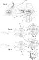
Fig. 1 shows a diagrammatic view of a wind tunnel according to the present invention; -
Fig. 2 shows a diagrammatic rear view of a motorcycle in rolled position when it is connected to an adjustable support of the wind tunnel according to the present invention; -
Fig. 3 shows a diagrammatic side view of a motorcycle in rolled position when it is connected to an adjustable support of the wind tunnel according to the present invention; -
Fig. 4 shows a diagrammatic top view of a simplified motorcycle in vertical position when it is connected to an adjustable support of the wind tunnel according to the present invention; -
Fig. 5 shows a diagrammatic top view of a simplified motorcycle in rolled position when it is connected to an adjustable support of the wind tunnel according to the present invention; -
Fig. 6 shows a diagrammatic rear view of a simplified motorcycle in vertical position when it is connected to an adjustable support of the wind tunnel according to the present invention; -
Fig. 7 shows a diagrammatic rear view of a simplified motorcycle in rolled position when it is connected to an adjustable support of the wind tunnel according to the present invention; -
Fig. 8 shows a diagrammatic rear view of a simplified motorcycle in rolled position when it is connected to a particular version of an adjustable support of the wind tunnel according to the present invention. - The following description of one or more embodiments of the invention refers to the accompanying drawings. The same reference numerals in the drawings identify identical or similar elements. The subject of the invention is defined by the appended claims. The technical details, structures, or features of the solutions described below can be mutually combined in any manner.
-
Reference numeral 1 inFig. 1 indicates a wind tunnel which comprises aplatform 2 on which amotorcycle 100 is arranged. Themotorcycle 100 is in the rolled position, i.e., tilted to a side. Specifically,motorcycle 100 is tilted to the left side. - The
motorcycle 100 is arranged in front of alarge fan 3, i.e., a device adapted to generate an air flow capable of entirely hitting themotorcycle 100. - The
wind tunnel 1 further comprisesrollers 16 configured to rotate upon the actuation of an engine (not shown). - The
rollers 16 are in contact with thewheels motorcycle 100. In particular, thefront roller 16 is in contact with thefront wheel 103 ofmotorcycle 100 and therear roller 16 is in contact with therear wheel 102. Twoopenings 17 are present onplatform 2, at saidwheels rollers 16 andwheels Fig. 2 . - The
rollers 16 move thewheels fan 3 blows air towardsmotorcycle 100. In an embodiment (not shown), there are no rollers and therefore the wheels ofmotorcycle 100 are stationary. In a further embodiment (not shown), the rollers are replaced by a belt which simulates the movement of the ground undermotorcycle 100. Said belt is moved by a motor and is adapted to rotate both wheels ofmotorcycle 100. Alternatively, the belt can be configured to move the wheels individually, as done byrollers 16. - In one version (not shown), the fans can be two in number, arranged on opposite sides with respect to
platform 2. Alternatively,fan 3 can be arranged only behindplatform 2. - In a known manner, the portions upstream and downstream of
platform 2, and therefore behind the fan(s) 3, can be fluidly connected to each other so as to recirculate the same air several times over inside thewind tunnel 1. This configuration type of thewind tunnel 1 is referred to as a "closed circuit" configuration type. Alternatively, the air flow rate is not recovered but continuously renewed. This type ofwind tunnel 1 is generally referred to as an "open circuit" type. -
Platform 2 can be configured to rotate with respect to a vertical axis with respect to theplatform 2 itself, so as to change the orientation ofmotorcycle 100 with respect to the direction of the air flow. - In order to support and tilt the
motorcycle 100, thewind tunnel 1 is provided with an adjustable support 4, shown inFigs. 1-8 . - The adjustable support 4 comprises a left actuated
column 5 and a right actuatedcolumn 6. The term "column" comprises any type of support adapted to support a given element, specifically the articulatedaxis 20, at a given height fromplatform 2. - The term "actuated column" is indicated more briefly below by the term "column".
- The articulated
axis 20 comprises three portions:left portion 7,right portion 8, andcentral portion 9. As clarified below, the portions of the articulated axis can also be two in number. - The
central portion 9 of the articulatedaxis 20 is connected to therear wheel axis 101 of themotorcycle 100 so that by tilting thecentral portion 9 by a given degree, therear wheel axis 101 also tilts by the same degree and accordingly themotorcycle 100 also tilts by the same degree. - The left and
right columns axis 20, respectively. Specifically, theleft column 5 is connected to theleft axis portion 7, while theright column 6 is coupled to theright axis portion 8. - The
columns platform 2 of therespective axis portions Figs. 2 ,7 . The mechanism allowing thecolumn column - The
columns platform 2. - The
columns platform 2. As shown inFigs. 1-3 , part of thecolumns platform 2, while another part of thecolumns platform 2. - As shown in
Figs. 1-7 , theleft axis portion 7 is rigidly connected to the left actuatedcolumn 5. Specifically, the rigid coupling is achieved by means of aclamping device 14. - The clamping
device 14 comprises a clamp configured to tighten anaxis portion 7. The clamps can be tightened with the aid of bolts. - An axis portion, which in
Figs. 6, 7 is theright axis portion 8, can slide with respect to therespective column 6. The slidingdevice 15 is a hinge configured to allow for a prismatic coupling between theportion 8 of the articulatedaxis 20 and thecolumn 6. - If one of the
axis portions respective column other axis portion respective column axis 20 is thus possible. It is also possible for bothaxis portions respective columns - Alternatively, both the
axis portions respective columns devices 14. Here, the articulatedaxis 20 is first clamped on one side, with aclamping device 14, then thecolumns central portion 9, and then the other end of the articulatedaxis 20 is clamped by means of afurther clamping device 14. - The
left axis portion 7 is hinged to thecentral portion 9 by means of aleft hinge 10, while theright axis portion 8 is hinged to the central portion by means of aright hinge 11. The articulatedaxis 20 can thus take several configurations depending on the angle obtained between theleft portion 7 and thecentral portion 9 and on the angle obtained between theright portion 8 and thecentral portion 9, as shown inFig. 7 . - The rotation axes 12, 13 of the respective hinges 10, 11 are substantially parallel to
platform 2, as shown inFig. 3 . Therefore, by varying the distance of theaxes platform 2, various tilt angles of thecentral portion 9 are obtained. The rotation axes 12, 13 are also parallel to the longitudinal axis of themotorcycle 100. - The
left 7 and right 8 portions of the articulatedaxis 20 are connected to therespective columns platform 2, theportions platform 2, as shown inFigs. 2 ,7 . Since theleft 7 and right 8 portions are hinged to thecentral portion 9, thecentral portion 9 tilts when the heights of theleft 7 and right 8 portions with respect toplatform 2 differ, as better shown inFigs. 2 ,5, 7 . - The angle between the
left column 5 and theleft axis portion 7 is fixed and is equal to 90°, as is the angle between theright column 6 and theright axis portion 8. - When the height of the
columns platform 2 differs, thecentral portion 9 tilts, as shown inFigs. 1, 2 ,3, 5, 7 . When the height of thecolumns platform 2 is the same, thecentral portion 9 is parallel toplatform 2, as shown inFigs. 4, 6 . - In particular, in
Figs. 4, 6 ,motorcycle 100 is not rolled but vertical with respect toplatform 2. Instead, inFigs. 5, 6 , as well as inFigs. 1-3 , themotorcycle 100 is in the rolled position, i.e., tilted to one side. InFigs. 4, 5 ,motorcycle 100 is only depicted by the radial profile of thewheels rear wheel axis 101 is also diagrammatically depicted. - The adjustment of the height of the
columns rear wheel 102, as it can be understood inFigs. 6, 7 . By varying the height of thecolumns rear wheel 102 is raised or lowered with respect toplatform 2. The adjustment of the height of thecolumns central portion 9 but also that therear wheel 102 must remain resting onplatform 2 orroller 16, as shown inFigs. 1, 2 ,3, 7 . - The
central portion 9 of the articulatedaxis 20 is fixed to therear wheel axis 101 by means of connectingmeans 18, also referred to aswheel clamps 18. These wheel clamps 18 are configured to laterally harpoon therear wheel axis 101 and constrain it to thecentral portion 9. For example, stops are connected to thecentral portion 9, and by means of a thread, can translate on thecentral portion 9 and act on side faces of thewheel pin 101. Thrust blocks adapted to allow for a relative rotation of the wheel clamps 18 with respect to therear wheel assembly 102 and/or the rear fork of themotorcycle 100 can be provided on thewheel clamps 18. Optionally, ball bearings or bushings can be inserted between therear wheel axis 101 and thecentral portion 9 of the articulatedaxis 20 to reduce the friction during the relative movements therebetween. - Preferably, the
central portion 9 is sized so as to pass inside therear wheel axis 101 when the latter is hollow, as shown inFigs. 2 ,6, 7 . - If the
rear wheel axis 101 is not hollow (which hypothesis is not shown), thecentral axis 9 is divided into two parts and each part is constrained to opposite sides ofmotorcycle 100, respectively. The connection with therear axis 101 is indeed preferable but not required. The lateral tilt ofmotorcycle 100 can also be achieved by connecting the adjustable support 4 to a different portion of themotorcycle 100. For example, the adjustable support 4 can be connected to the front portion ofmotorcycle 100, and in particular to thefront wheel 103, frame, orside 104 thereof. In essence, the suggested mechanism can usefully tilt themotorcycle 100 even if it is connected to any part of the motorcycle adapted to transfer the tilt movement to the entire vehicle. - The
central portion 9 of the articulatedaxis 20 has a width D2 which is less than the inner distance between thecolumns Figs. 6, 7, 8 . - In an alternative embodiment shown in
Fig. 8 , the articulatedaxis 20 comprises two portions, not three. Afirst portion 19, either right or left, is rigidly constrained to therespective column 5 and is connected by means of afirst hinge 21 to thecentral portion 9. Thecentral portion 9 is then pivotally connected by means of asecond hinge 22 to theother column 6. The first and second hinges 21, 22 have rotation axes parallel toplatform 2. All the other features of this embodiment coincide with the previous embodiment described. - The articulated
axis 20 thus conceived can be used even autonomously on existing wind tunnels, thus facilitating aerodynamic tests in which themotorcycle 100 is tilted. Known wind tunnels have a connection axis with therear wheel 101 of themotorcycle 100 of rigid and monolithic type, and the actuated columns do not have a sufficient range to allow simulating roll angles comparable to the maximum roll angle of the motorcycle. Therefore, current wind tunnels do not allow simulating roll conditions which usually occur on the track withracing motorcycles 100, which reach roll tilts of 60°-65°. - In conclusion, it is apparent that the invention thus devised is susceptible to several modifications or variations, all falling within the invention; moreover, all details are replaceable with technically equivalent elements. In practice, the quantities could be changed depending on the technical needs.
-
- 1
- wind tunnel
- 2
- platform
- 3
- fan
- 4
- adjustable support
- 5
- left actuated column
- 6
- right actuated column
- 7
- left axis portion
- 8
- right axis portion
- 9
- central axis portion
- 10
- left hinge
- 11
- right hinge
- 12
- left hinging axis
- 13
- right hinging axis
- 14
- clamping device
- 15
- sliding device
- 16
- roller
- 17
- window
- 18
- wheel clamp
- 19
- first axis portion
- 20
- articulated axis
- 21
- first hinge
- 22
- second hinge
- 100
- motorcycle
- 101
- rear wheel axis
- 102
- rear wheel
- 103
- front wheel
- 104
- side
- D1
- distance between columns
- D2
- width of central axis portion
Claims (11)
- A wind tunnel (1) comprising:- a platform (2) on which a motorcycle (100) can be placed;- at least one fan (3) arranged in front of and/or behind the platform (2) so as to generate an air flow which flows longitudinally over the platform (2);- an adjustable support (4) configured to be connected by means of an articulated axis (20) to a portion of the motorcycle (100), preferably to the rear wheel axis (101) thereof, wherein the adjustable support (4) comprises:- the articulated axis (20), which comprises at least two axis portions (7, 8, 9) hinged to each other;- a left actuated column (5) and a right actuated column (6) connected to opposite ends of the articulated axis (20), respectively.
- A wind tunnel (1) according to claim 1, wherein the articulated axis (20) comprises a left axis portion (7), a right axis portion (8), and a central axis portion (9), and wherein the central axis portion (9) is hinged by means of a left hinge (10) to the left axis portion (7) and by means of a right hinge (11) to the right axis portion (8).
- A wind tunnel (1) according to claim 2, wherein the left and right hinges (10, 11) have hinging axes (12, 13) substantially parallel to the platform (2).
- A wind tunnel (1) according to claim 2 or 3, wherein the left axis portion (7) is slidingly coupled to the left actuated column (5) or the right axis portion (8) is slidingly coupled to the right actuated column (6).
- A wind tunnel (1) according to any one of claims 2 to 4, wherein the left actuated column (5) comprises a clamping device (14) configured to clamp the left axis portion (7) and/or the right actuated column (6) comprises a clamping device (14) configured to clamp the right axis portion (8).
- A wind tunnel (1) according to any one of the preceding claims, wherein the central axis portion (9) is configured to pass in the rear wheel axis (101) of the motorcycle (100).
- A wind tunnel (1) according to any one of the preceding claims, wherein the central axis portion (9) comprises connecting means (18) to connect the rear wheel axis (101) of the motorcycle (100) to the central axis portion (9).
- A wind tunnel (1) according to any one of the preceding claims, wherein the left and right actuated columns (5, 6) are arranged vertically with respect to the platform (2).
- A wind tunnel (1) according to any one of the preceding claims, wherein the left and right actuated columns (5, 6) are configured to move up and down, in an independent manner, with respect to the platform (2).
- A wind tunnel (1) according to any one of the preceding claims, wherein the width of the central axis portion (9) is greater than or equal to half the distance between the left and right actuated columns (5, 6).
- A wind tunnel (1) according to any one of the preceding claims, further comprising at least one roller (16) arranged below the platform (2) and in contact with the wheel(s) (102, 103) of the motorcycle (100) by means of through opening(s) (17) provided on the platform (2) at said wheel(s) (102, 103).
Applications Claiming Priority (1)
| Application Number | Priority Date | Filing Date | Title |
|---|---|---|---|
| IT102023000011217A IT202300011217A1 (en) | 2023-06-01 | 2023-06-01 | WIND TUNNEL |
Publications (3)
| Publication Number | Publication Date |
|---|---|
| EP4471398A1 true EP4471398A1 (en) | 2024-12-04 |
| EP4471398C0 EP4471398C0 (en) | 2025-10-22 |
| EP4471398B1 EP4471398B1 (en) | 2025-10-22 |
Family
ID=87800946
Family Applications (1)
| Application Number | Title | Priority Date | Filing Date |
|---|---|---|---|
| EP24176937.1A Active EP4471398B1 (en) | 2023-06-01 | 2024-05-21 | Wind tunnel |
Country Status (2)
| Country | Link |
|---|---|
| EP (1) | EP4471398B1 (en) |
| IT (1) | IT202300011217A1 (en) |
Citations (6)
| Publication number | Priority date | Publication date | Assignee | Title |
|---|---|---|---|---|
| US4978300A (en) * | 1989-03-16 | 1990-12-18 | Bernard Fried Racing Enterprises | High performance motorcycle simulator |
| US20020055422A1 (en) * | 1995-05-18 | 2002-05-09 | Matthew Airmet | Stationary exercise apparatus adaptable for use with video games and including springed tilting features |
| US8505374B1 (en) * | 2009-12-10 | 2013-08-13 | Dynocom Industries, Inc. | Portable on vehicle dynamometer |
| US20150279228A1 (en) * | 2012-10-26 | 2015-10-01 | Guy François, Joseph DERICQUEBOURG | Real motorbike-riding simulator |
| DE102018221677A1 (en) | 2018-12-13 | 2020-06-18 | Aip Gmbh & Co. Kg | Holding device with a changing device for modules of a wind tunnel test bench and wind tunnel test bench |
| WO2023041722A1 (en) * | 2021-09-17 | 2023-03-23 | Kristl, Seibt & Co. Gesellschaft M.B.H. | Method for stabilizing a driverless single-track motor vehicle on a roller dynamometer, and stabilizing device, roller dynamometer and test system |
-
2023
- 2023-06-01 IT IT102023000011217A patent/IT202300011217A1/en unknown
-
2024
- 2024-05-21 EP EP24176937.1A patent/EP4471398B1/en active Active
Patent Citations (6)
| Publication number | Priority date | Publication date | Assignee | Title |
|---|---|---|---|---|
| US4978300A (en) * | 1989-03-16 | 1990-12-18 | Bernard Fried Racing Enterprises | High performance motorcycle simulator |
| US20020055422A1 (en) * | 1995-05-18 | 2002-05-09 | Matthew Airmet | Stationary exercise apparatus adaptable for use with video games and including springed tilting features |
| US8505374B1 (en) * | 2009-12-10 | 2013-08-13 | Dynocom Industries, Inc. | Portable on vehicle dynamometer |
| US20150279228A1 (en) * | 2012-10-26 | 2015-10-01 | Guy François, Joseph DERICQUEBOURG | Real motorbike-riding simulator |
| DE102018221677A1 (en) | 2018-12-13 | 2020-06-18 | Aip Gmbh & Co. Kg | Holding device with a changing device for modules of a wind tunnel test bench and wind tunnel test bench |
| WO2023041722A1 (en) * | 2021-09-17 | 2023-03-23 | Kristl, Seibt & Co. Gesellschaft M.B.H. | Method for stabilizing a driverless single-track motor vehicle on a roller dynamometer, and stabilizing device, roller dynamometer and test system |
Non-Patent Citations (1)
| Title |
|---|
| SUZUKI GLOBAL: "FOCUSED ON QUALITY | Aerodynamic Testing | Suzuki", 8 June 2022 (2022-06-08), XP093109175, Retrieved from the Internet <URL:https://www.youtube.com/watch?v=vQsW1qwfrdY> [retrieved on 20231205] * |
Also Published As
| Publication number | Publication date |
|---|---|
| EP4471398C0 (en) | 2025-10-22 |
| IT202300011217A1 (en) | 2024-12-01 |
| EP4471398B1 (en) | 2025-10-22 |
Similar Documents
| Publication | Publication Date | Title |
|---|---|---|
| US8607626B2 (en) | Restraint system for restraining a test article in a selected vertical position relative to a movable belt | |
| US5111685A (en) | Roadway simulator restraint | |
| US8186207B2 (en) | Strut assembly for transfering load from a movable belt | |
| JP5011361B2 (en) | Tire testing machine | |
| CN108397596B (en) | A kind of ocean engineering submarine pipeline stringer | |
| US4008785A (en) | Transport device for movement of an operator up and down a utility pole | |
| US8651501B1 (en) | Three wheeled automotive dolly | |
| CN101460821A (en) | System for simulating the ground effect for testing vehicles or their simulacra in wind tunnels | |
| EP4471398B1 (en) | Wind tunnel | |
| US8950760B1 (en) | Three wheeled automotive dolly and method of use | |
| US20230089584A1 (en) | Device for accommodating and for releasing a payload on an aerial vehicle | |
| CN114838962A (en) | Front suspension system testing device | |
| CN210375704U (en) | Aeroengine test bench | |
| CN119374923A (en) | A motorcycle frame fatigue testing device | |
| CN116569017A (en) | Tire test bench with hexapod assembly | |
| CN106679986A (en) | Universal buck for sled test | |
| JP7500919B2 (en) | Tilt mechanism for single track dummy vehicle | |
| JP2009180715A (en) | Tire testing device and tire testing method | |
| CN109341738B (en) | Tilting and swinging test bed with changeable swinging center | |
| CN110361199B (en) | A kind of steering wheel man-machine verification method | |
| CN110031236B (en) | Dynamic environmental parameter-based whole vehicle performance dynamic simulation test system and method | |
| US4199166A (en) | Tandem wheel apparatus | |
| CN106908257A (en) | Steering test bench | |
| CN116929592B (en) | Temperature measuring instrument data acquisition and detection device and detection method | |
| US4507835A (en) | Adjustable press jig for front wheel strut assembly |
Legal Events
| Date | Code | Title | Description |
|---|---|---|---|
| PUAI | Public reference made under article 153(3) epc to a published international application that has entered the european phase |
Free format text: ORIGINAL CODE: 0009012 |
|
| STAA | Information on the status of an ep patent application or granted ep patent |
Free format text: STATUS: THE APPLICATION HAS BEEN PUBLISHED |
|
| AK | Designated contracting states |
Kind code of ref document: A1 Designated state(s): AL AT BE BG CH CY CZ DE DK EE ES FI FR GB GR HR HU IE IS IT LI LT LU LV MC ME MK MT NL NO PL PT RO RS SE SI SK SM TR |
|
| STAA | Information on the status of an ep patent application or granted ep patent |
Free format text: STATUS: REQUEST FOR EXAMINATION WAS MADE |
|
| 17P | Request for examination filed |
Effective date: 20250207 |
|
| GRAP | Despatch of communication of intention to grant a patent |
Free format text: ORIGINAL CODE: EPIDOSNIGR1 |
|
| STAA | Information on the status of an ep patent application or granted ep patent |
Free format text: STATUS: GRANT OF PATENT IS INTENDED |
|
| RIC1 | Information provided on ipc code assigned before grant |
Ipc: G01M 17/007 20060101ALI20250527BHEP Ipc: G01M 9/04 20060101AFI20250527BHEP |
|
| INTG | Intention to grant announced |
Effective date: 20250616 |
|
| RAP3 | Party data changed (applicant data changed or rights of an application transferred) |
Owner name: PIAGGIO & C. S.P.A. |
|
| GRAS | Grant fee paid |
Free format text: ORIGINAL CODE: EPIDOSNIGR3 |
|
| GRAA | (expected) grant |
Free format text: ORIGINAL CODE: 0009210 |
|
| STAA | Information on the status of an ep patent application or granted ep patent |
Free format text: STATUS: THE PATENT HAS BEEN GRANTED |
|
| AK | Designated contracting states |
Kind code of ref document: B1 Designated state(s): AL AT BE BG CH CY CZ DE DK EE ES FI FR GB GR HR HU IE IS IT LI LT LU LV MC ME MK MT NL NO PL PT RO RS SE SI SK SM TR |
|
| REG | Reference to a national code |
Ref country code: CH Ref legal event code: F10 Free format text: ST27 STATUS EVENT CODE: U-0-0-F10-F00 (AS PROVIDED BY THE NATIONAL OFFICE) Effective date: 20251022 Ref country code: GB Ref legal event code: FG4D |
|
| REG | Reference to a national code |
Ref country code: IE Ref legal event code: FG4D |
|
| U01 | Request for unitary effect filed |
Effective date: 20251024 |
|
| U07 | Unitary effect registered |
Designated state(s): AT BE BG DE DK EE FI FR IT LT LU LV MT NL PT RO SE SI Effective date: 20251030 |
|
| PG25 | Lapsed in a contracting state [announced via postgrant information from national office to epo] |
Ref country code: ES Free format text: LAPSE BECAUSE OF FAILURE TO SUBMIT A TRANSLATION OF THE DESCRIPTION OR TO PAY THE FEE WITHIN THE PRESCRIBED TIME-LIMIT Effective date: 20251022 |
|
| PG25 | Lapsed in a contracting state [announced via postgrant information from national office to epo] |
Ref country code: NO Free format text: LAPSE BECAUSE OF FAILURE TO SUBMIT A TRANSLATION OF THE DESCRIPTION OR TO PAY THE FEE WITHIN THE PRESCRIBED TIME-LIMIT Effective date: 20260122 |
|
| PG25 | Lapsed in a contracting state [announced via postgrant information from national office to epo] |
Ref country code: HR Free format text: LAPSE BECAUSE OF FAILURE TO SUBMIT A TRANSLATION OF THE DESCRIPTION OR TO PAY THE FEE WITHIN THE PRESCRIBED TIME-LIMIT Effective date: 20251022 |
|
| PG25 | Lapsed in a contracting state [announced via postgrant information from national office to epo] |
Ref country code: RS Free format text: LAPSE BECAUSE OF FAILURE TO SUBMIT A TRANSLATION OF THE DESCRIPTION OR TO PAY THE FEE WITHIN THE PRESCRIBED TIME-LIMIT Effective date: 20260122 |
|
| PG25 | Lapsed in a contracting state [announced via postgrant information from national office to epo] |
Ref country code: IS Free format text: LAPSE BECAUSE OF FAILURE TO SUBMIT A TRANSLATION OF THE DESCRIPTION OR TO PAY THE FEE WITHIN THE PRESCRIBED TIME-LIMIT Effective date: 20260222 |
|
| PG25 | Lapsed in a contracting state [announced via postgrant information from national office to epo] |
Ref country code: PL Free format text: LAPSE BECAUSE OF FAILURE TO SUBMIT A TRANSLATION OF THE DESCRIPTION OR TO PAY THE FEE WITHIN THE PRESCRIBED TIME-LIMIT Effective date: 20251022 |
|
| U20 | Renewal fee for the european patent with unitary effect paid |
Year of fee payment: 3 Effective date: 20260325 |