EP4471365A1 - Stream splitter for double-contained pipe system - Google Patents
Stream splitter for double-contained pipe system Download PDFInfo
- Publication number
- EP4471365A1 EP4471365A1 EP24460017.7A EP24460017A EP4471365A1 EP 4471365 A1 EP4471365 A1 EP 4471365A1 EP 24460017 A EP24460017 A EP 24460017A EP 4471365 A1 EP4471365 A1 EP 4471365A1
- Authority
- EP
- European Patent Office
- Prior art keywords
- heat exchanger
- exchanger
- pipe
- channels
- stream
- Prior art date
- Legal status (The legal status is an assumption and is not a legal conclusion. Google has not performed a legal analysis and makes no representation as to the accuracy of the status listed.)
- Pending
Links
Images






Classifications
-
- F—MECHANICAL ENGINEERING; LIGHTING; HEATING; WEAPONS; BLASTING
- F28—HEAT EXCHANGE IN GENERAL
- F28D—HEAT-EXCHANGE APPARATUS, NOT PROVIDED FOR IN ANOTHER SUBCLASS, IN WHICH THE HEAT-EXCHANGE MEDIA DO NOT COME INTO DIRECT CONTACT
- F28D7/00—Heat-exchange apparatus having stationary tubular conduit assemblies for both heat-exchange media, the media being in contact with different sides of a conduit wall
- F28D7/10—Heat-exchange apparatus having stationary tubular conduit assemblies for both heat-exchange media, the media being in contact with different sides of a conduit wall the conduits being arranged one within the other, e.g. concentrically
- F28D7/103—Heat-exchange apparatus having stationary tubular conduit assemblies for both heat-exchange media, the media being in contact with different sides of a conduit wall the conduits being arranged one within the other, e.g. concentrically consisting of more than two coaxial conduits or modules of more than two coaxial conduits
-
- F—MECHANICAL ENGINEERING; LIGHTING; HEATING; WEAPONS; BLASTING
- F24—HEATING; RANGES; VENTILATING
- F24F—AIR-CONDITIONING; AIR-HUMIDIFICATION; VENTILATION; USE OF AIR CURRENTS FOR SCREENING
- F24F11/00—Control or safety arrangements
- F24F11/70—Control systems characterised by their outputs; Constructional details thereof
- F24F11/72—Control systems characterised by their outputs; Constructional details thereof for controlling the supply of treated air, e.g. its pressure
- F24F11/74—Control systems characterised by their outputs; Constructional details thereof for controlling the supply of treated air, e.g. its pressure for controlling air flow rate or air velocity
-
- F—MECHANICAL ENGINEERING; LIGHTING; HEATING; WEAPONS; BLASTING
- F24—HEATING; RANGES; VENTILATING
- F24F—AIR-CONDITIONING; AIR-HUMIDIFICATION; VENTILATION; USE OF AIR CURRENTS FOR SCREENING
- F24F12/00—Use of energy recovery systems in air conditioning, ventilation or screening
- F24F12/001—Use of energy recovery systems in air conditioning, ventilation or screening with heat-exchange between supplied and exhausted air
- F24F12/006—Use of energy recovery systems in air conditioning, ventilation or screening with heat-exchange between supplied and exhausted air using an air-to-air heat exchanger
-
- F—MECHANICAL ENGINEERING; LIGHTING; HEATING; WEAPONS; BLASTING
- F24—HEATING; RANGES; VENTILATING
- F24F—AIR-CONDITIONING; AIR-HUMIDIFICATION; VENTILATION; USE OF AIR CURRENTS FOR SCREENING
- F24F13/00—Details common to, or for air-conditioning, air-humidification, ventilation or use of air currents for screening
- F24F13/08—Air-flow control members, e.g. louvres, grilles, flaps or guide plates
-
- F—MECHANICAL ENGINEERING; LIGHTING; HEATING; WEAPONS; BLASTING
- F24—HEATING; RANGES; VENTILATING
- F24F—AIR-CONDITIONING; AIR-HUMIDIFICATION; VENTILATION; USE OF AIR CURRENTS FOR SCREENING
- F24F13/00—Details common to, or for air-conditioning, air-humidification, ventilation or use of air currents for screening
- F24F13/08—Air-flow control members, e.g. louvres, grilles, flaps or guide plates
- F24F13/10—Air-flow control members, e.g. louvres, grilles, flaps or guide plates movable, e.g. dampers
- F24F13/12—Air-flow control members, e.g. louvres, grilles, flaps or guide plates movable, e.g. dampers built up of sliding members
-
- F—MECHANICAL ENGINEERING; LIGHTING; HEATING; WEAPONS; BLASTING
- F28—HEAT EXCHANGE IN GENERAL
- F28D—HEAT-EXCHANGE APPARATUS, NOT PROVIDED FOR IN ANOTHER SUBCLASS, IN WHICH THE HEAT-EXCHANGE MEDIA DO NOT COME INTO DIRECT CONTACT
- F28D7/00—Heat-exchange apparatus having stationary tubular conduit assemblies for both heat-exchange media, the media being in contact with different sides of a conduit wall
- F28D7/16—Heat-exchange apparatus having stationary tubular conduit assemblies for both heat-exchange media, the media being in contact with different sides of a conduit wall the conduits being arranged in parallel spaced relation
- F28D7/163—Heat-exchange apparatus having stationary tubular conduit assemblies for both heat-exchange media, the media being in contact with different sides of a conduit wall the conduits being arranged in parallel spaced relation with conduit assemblies having a particular shape, e.g. square or annular; with assemblies of conduits having different geometrical features; with multiple groups of conduits connected in series or parallel and arranged inside common casing
- F28D7/1669—Heat-exchange apparatus having stationary tubular conduit assemblies for both heat-exchange media, the media being in contact with different sides of a conduit wall the conduits being arranged in parallel spaced relation with conduit assemblies having a particular shape, e.g. square or annular; with assemblies of conduits having different geometrical features; with multiple groups of conduits connected in series or parallel and arranged inside common casing the conduit assemblies having an annular shape; the conduits being assembled around a central distribution tube
-
- F—MECHANICAL ENGINEERING; LIGHTING; HEATING; WEAPONS; BLASTING
- F28—HEAT EXCHANGE IN GENERAL
- F28D—HEAT-EXCHANGE APPARATUS, NOT PROVIDED FOR IN ANOTHER SUBCLASS, IN WHICH THE HEAT-EXCHANGE MEDIA DO NOT COME INTO DIRECT CONTACT
- F28D7/00—Heat-exchange apparatus having stationary tubular conduit assemblies for both heat-exchange media, the media being in contact with different sides of a conduit wall
- F28D7/16—Heat-exchange apparatus having stationary tubular conduit assemblies for both heat-exchange media, the media being in contact with different sides of a conduit wall the conduits being arranged in parallel spaced relation
- F28D7/1684—Heat-exchange apparatus having stationary tubular conduit assemblies for both heat-exchange media, the media being in contact with different sides of a conduit wall the conduits being arranged in parallel spaced relation the conduits having a non-circular cross-section
-
- F—MECHANICAL ENGINEERING; LIGHTING; HEATING; WEAPONS; BLASTING
- F28—HEAT EXCHANGE IN GENERAL
- F28F—DETAILS OF HEAT-EXCHANGE AND HEAT-TRANSFER APPARATUS, OF GENERAL APPLICATION
- F28F13/00—Arrangements for modifying heat-transfer, e.g. increasing, decreasing
- F28F13/06—Arrangements for modifying heat-transfer, e.g. increasing, decreasing by affecting the pattern of flow of the heat-exchange media
-
- F—MECHANICAL ENGINEERING; LIGHTING; HEATING; WEAPONS; BLASTING
- F28—HEAT EXCHANGE IN GENERAL
- F28F—DETAILS OF HEAT-EXCHANGE AND HEAT-TRANSFER APPARATUS, OF GENERAL APPLICATION
- F28F9/00—Casings; Header boxes; Auxiliary supports for elements; Auxiliary members within casings
- F28F9/02—Header boxes; End plates
- F28F9/026—Header boxes; End plates with static flow control means, e.g. with means for uniformly distributing heat exchange media into conduits
- F28F9/0265—Header boxes; End plates with static flow control means, e.g. with means for uniformly distributing heat exchange media into conduits by using guiding means or impingement means inside the header box
- F28F9/0268—Header boxes; End plates with static flow control means, e.g. with means for uniformly distributing heat exchange media into conduits by using guiding means or impingement means inside the header box in the form of multiple deflectors for channeling the heat exchange medium
-
- F—MECHANICAL ENGINEERING; LIGHTING; HEATING; WEAPONS; BLASTING
- F28—HEAT EXCHANGE IN GENERAL
- F28D—HEAT-EXCHANGE APPARATUS, NOT PROVIDED FOR IN ANOTHER SUBCLASS, IN WHICH THE HEAT-EXCHANGE MEDIA DO NOT COME INTO DIRECT CONTACT
- F28D7/00—Heat-exchange apparatus having stationary tubular conduit assemblies for both heat-exchange media, the media being in contact with different sides of a conduit wall
- F28D7/10—Heat-exchange apparatus having stationary tubular conduit assemblies for both heat-exchange media, the media being in contact with different sides of a conduit wall the conduits being arranged one within the other, e.g. concentrically
- F28D7/14—Heat-exchange apparatus having stationary tubular conduit assemblies for both heat-exchange media, the media being in contact with different sides of a conduit wall the conduits being arranged one within the other, e.g. concentrically both tubes being bent
Definitions
- the subject of the invention is a new and innovative stream splitter for double-contained pipe systems, for mixing and diverting streams and for heat exchangers having a fan heat exchanger and exchanger systems, integrated with an electrostatic filter and/or ioniser, and stream splitter pattern, for enabling the redirection of streams from the inner pipe to the casing pipe and from the casing pipe to the inner pipe, with no pressure separation of the streams before and after separation and with no significant loss of flow dynamics, as well as for mixing the streams of the casing pipe with the streams of the inner pipe, for household use, industrial use and for use in municipal services and for others uses related to fluid thermodynamics. Proper operation of the device is ensured on condition that the tightness of the splitter inside the casing pipe and the tightness of the connection with the inner pipe is maintained.
- Various types of stream splitters used in fluid thermodynamics, including for ventilation devices, are known.
- a ventilation system with heat recuperation in which two concentric flow cylinders are placed inside a hole between the outer and inner surfaces, between which, on the outer surface of the inner cylinder, a corrugated heat exchanger is installed, and additionally, on the inner surface of the cylinder, external and internal fans are installed opposite one another.
- double-contained pipe systems known in the state of the art, used for such purposes as water treatment, galvanizing, chemical, automotive industries, etc.
- the inner pipe is commonly used for transporting the medium, whereas the casing pipe protects potential exposure of the surroundings, including people, property and the natural environment to damage and danger resulting from leakage.
- the differentiation of pressures and flow characteristics within double-contained pipe systems is quite common, where the pressure in the casing pipe may differ significantly from the pressure of the medium within the inner pipe, making access to the medium difficult.
- the solution according to the invention owing to its design, facilitates overcoming these inconveniences by enabling sectional reversal of the system and providing easier access to the medium by redirecting it from the inner pipe to the casing pipe, offering the possibility of multiple reversal/restoration of the system, with no need for losing or separating the pressures of the streams before and after their separation, and without the use of bulkheads or bypasses or the periodic closure of flows.
- the device can effectively function as a dual flow straight tube co-current or counter-current heat exchanger, facilitating the separation and reconnection of a single system to a double system (for example, performing the function of circulation for reheating of the external heat pump exchanger to protect it against undesirable icing).
- the solution according to the invention may function as a mixer of fluids to be used in a wide range of technological processes for mixing, dosing or dispersion of media with different temperature properties, various content, flow dynamics and pressure.
- Heat exchangers having a double-contained pipe system design are known in state of the art.
- the fluid flows from the casing pipe into the straight tube counter-current exchanger. Having passed through the channels in a system of alternating directions of the medium flow from the casing pipe and inner pipe, in the final section of the heat exchanger, the fluid enters channels where flow is blocked in the straight direction and which have an opening at an angle of 90°.
- the opening takes the form of perforation in the inner pipe and serves to divert the fluid to the interior of the inner pipe, where an exhaust fan is installed.
- the inner pipe serves as an exhaust pipe (from the outside of the facade) or as an air supply pipe (from the inside of the building), while the casing pipe serves as an air intake (from the outside of the façade) and air exhaust pipe (from the inside of the building); such a layout cannot be possibly reversed.
- the solution according to the invention owing to its design and the location of stream splitters at the beginning and end of the exchanger, converts the flows in double contained pipe system into alternating multi-channel flows typical of straight tube counter-current or co-current heat exchangers known in the state of the art that have an alternating system of channels arranged radially relative to the longitudinal axis of the system, and other exchangers featuring a system of channels known in the state of the art.
- the splitter has inlet and outlet openings of the channels through which the fluid flows through the device. These openings are located in a straightforward direction relative to the direction of flow with alternating partial plugging and opening of the channel with regard to the inner pipe.
- Each of the straight-line channels of the heat exchanger remains simultaneously partially open in the straightforward direction and partially plugged in the straightforward direction, diverting the streams through the plugged surface at an angle towards the inside or outside of the inner pipe of the double-contained pipe system. As a result, no significant changes in the flow direction of the streams occur, effectively separating the streams.
- the heat exchanger (in the sense of the heat exchange surface) occupies a relatively small space between the casing pipe and the inner pipe, which adversely affects its efficiency.
- the solution according to the invention overcomes this difficulty. This is possible owing to the innovative design of the splitter and the use of a culvert pipe that connects and stiffens the splitters placed at opposite ends of the heat exchanger/pipe system; the surface where the heat exchange occurs occupies the space between the casing pipe and the culvert pipe, as a result, the heat exchange surface of the exchanger becomes almost twice as large as elsewhere while retaining the same device shape and volume as compared to heat exchangers known in the state of the art.
- the culvert pipe can possibly be used as a passage through the device or for diverting the airflow for the purpose of bypass-type circumvention.
- openings in the splitters located at opposite ends of the heat exchanger/pipe system which advantageously come in a triangular shape (which results from the radial layout of channels relative to the longitudinal axis) and are alternately open and plugged relative to the inner pipe - the flowing fluid, regardless of the direction of the flow, is separated in a straightforward direction with a slight deviation from the desired direction; this positively influenced the reduction of flow resistance, an increase in the efficiency of the heat exchanger, and the reduction of undesirable turbulence and noise.
- This slight deviation in the straightforward direction relative to the desired flow direction results from the separation of the streams to the interior or outside the inner pipe and is caused by the aerodynamic profiling (extension) of the channel plug shape.
- the shape of the openings - alternating inlets and channel plugging in each of the stream splitters located at opposite ends of the heat exchanger/pipe system enables the installation of a flange for securing the connection of channels of a double contained pipe system or for securing a channel fan with a traditional hub or a rim-driven fan (so-called "rim-driven”).
- the fixing flange or even the entire splitter should be made of elastomers of selected hardness, such as polypropylene. The use of an elastomer supports the reduction of vibrations and the elimination of noise from the exchanger and double-contained pipe systems.
- the use of profiled, advantageously triangular shapes of alternating inlets and channel plugging, given their wedge-shaped aerodynamic extension, significantly increases the steam flow surface at the point of the separation of streams, as the surface of the inlet and channel plugging increases with the rise in their aerodynamic extension angle. Thanks to overcoming this limitation, the solution according to the invention can be equipped with a greater number of narrower channels (folds) as compared to solutions known in the state of the art. This significantly improves the efficiency of the solution.
- the essence of the invention is that on the flange in the shape of a circle or a shape adapted to the shape of the casing pipe, plugs and openings of channels are located alternately to the inside and outside relative to the inner pipe, the number and shape of which correspond to the number and shape of the heat exchanger channels, with the inlet and outlet of each channel redirected to the outside and inside of the inner pipe; whereby the displacement by one fold (channel) of one of the two splitters causes the same channel to be open on one end in the outer part and simultaneously plugged in the inner part of the inner pipe, and open on the other end in the inner part and simultaneously plugged in the outer part of the inner pipe; whereby the plugs and openings of the channels of the splitter are extended, advantageously aerodynamically, into a shape similar to a triangle/wedge, the inclination angles of the walls of which determine the stream thrust angle and determine the change in the thrust direction of streams in relation to their separation; whereby between the passage and the rim a displacement occurs relative to the longitudinal axis by one
- stream splitter blades are placed in the inner and outer parts of the inner pipe, while on the fold ridges (channels) of the exchanger, fan impeller blades known in the state of the art are placed, whereby the stream splitter blades capture the streams and direct them to the exchanger channels; whereby the channel walls of the heat exchanger constitute also the fan impeller blades; whereby the stream splitter blades and the fan impeller blades are advantageously combined into a single blade; while through the rim and channels, the stream splitter is combined with the opposite rim and the stream splitter to form a heat exchanger; whereby the heat exchanger, by combining the stream splitters with each other, is combined with the following stream splitters into heat exchanger systems; while the rim of the heat exchanger and the channels of the heat exchanger may have a hexagonal shape in cross-section
- the rim in the variation made of a solid element, enables the attachment, in a method known in the state of the art, of a metallic foil or other membrane having parameters (known in the state of the art) of an unfixed shape enabling the formation of channels that ensure tightness and thermal transfer of the foil heat exchanger.
- Fluid streams for instance, airstreams, separated into internal and external ones relative to the inner pipe of the double-contained pipe system as a result of their flowing through the splitter, are separated by alternating plugs and inlets on the outside of the inner pipe and plugs and outlets located oppositely inside the inner pipe.
- the fluid flows into the exchanger in the area outside the inner pipe and flows out of the exchanger inside the casing pipe, if the stream splitters located at opposite ends of the heat exchanger/pipe system differ from each other by the displacement of the inlet and outlet by one channel in such a way that the fluid inlet to the channel on the outside of the inner pipe is concurrently plugged on the inner side of the inner pipe, whereas at the other end, the channel is open on the inner side of the inner pipe and plugged on the outside of the inner pipe.
- the displacement of the inlet and outlet by one channel results in the streams flowing through the heat exchanger being redirected to the opposite pipe, that is, if the inlet to the exchanger comes from the casing pipe, the outlet is directed to the inner pipe, whereas if the inlet comes from the inner pipe, the outlet is directed to the casing pipe. If the stream splitters placed at opposite ends of the heat exchanger/pipe system do not differ from one another by the displacement of the inlet and outlet by one channel, then the inlet and outlet of each channel of the straight heat exchanger will be located in the same pipe of the double contained pipe system, without diverting.
- the inlets and outlets of the counter-current exchanger channels are located alternately, on one side of the exchanger or the other.
- the streams supplied by a pipe-in-pipe system, split into a number of alternating channels by the rim effectively act as a mixer, in which static regulation is possible by adapting the cross-sections of the casing and inner pipe, as well as the number of mixed channels/streams to the characteristics of the flow and the transported medium, and in which dynamic adjustment is possible if the position of the intermediate transition relative to the edge and flange is set.
- it is not necessary to conchannel the channels out from the rim or the use of such channels is limited, while the alternating streams mixed in this way can be transported as one medium through the casing or inner pipe.
- the structure of the stream splitter comprises a splitter of streams from a double-contained pipe system into a system of alternating channels.
- the counter-current streams are advantageously directed in a straightforward direction relative to the flow direction.
- Streams in an alternating system supply and exhaust, or supply and exhaust
- a stream splitter by using a stream splitter, are redirected into the space of the inner and casing pipes (a supply stream with a supply stream, whereas an exhaust stream with an exhaust stream; supply and discharge analogically).
- the stream splitter comes with space for a culvert pipe, which serves the purpose of stiffening the exchanger and can also function as a by-pass or a channel.
- the fluid passing through the stream splitter (regardless of the flow direction) is redirected to the channel (casing or inner pipe).
- the fluid is distributed in a straightforward direction relative to the direction in which it flows through the exchanger.
- the fluid is pushed, flowing to the opposite pipe (e.g. from the casing to the inner pipe).
- each inlet and outlet of the channel is divided into two parts - the outside or the inside of the inner pipe, i.e. into the inner or casing pipe.
- Each channel is advantageously open on one end by the stream splitter on the outside part of the inner pipe, while on the other end, it is open only in the inner part of the inner pipe.
- the fluid passes through a heat exchanger, while at the other end of the channels, plugs are located outside the inner pipe and open to the interior of the inner pipe.
- plugs are located outside the inner pipe and open to the interior of the inner pipe.
- the splitters can be adjusted relative to one another.
- the movement of one splitter relative to the other enables moving the passage by one fold (channel). This movement is limited.
- the connection of all elements is obtained by clicking them on a keyway connection (groove) or in any other way known in the state of the art that makes adjustment possible.
- the air is supplied and discharged from and to the same channel of the double-contained pipe system.
- this solution leads to creating a set of two or more splitters for double contained pipe systems and co-current or counter-current flows for the construction of a heat recuperator having a straight co-current or straight counter-current exchanger or any other type known in the state of the art, in which the layout of the splitter rim affects the layout of channels in the heat exchanger, while the rim makes it possible to attach, in a manner known in the state of the art (glueing, ultrasonic welding, clamping, etc.), a metallic foil and any other membrane whose parameters enable forming and ensuring tightness and thermal transfer of the foil heat exchanger
- the twist can be modified with the use of solutions known in the state of the art, and the twist intensity depends on the stream flow dynamics to obtain optimal efficiency for a given flow velocity.
- the casing pipe and inner pipe can take any shape known in the state of the art, such as round, square, triangular, or hexagonal.
- the heat exchanger channels can take any shape known in the state of the art, determined by the shape of the rim.
- stream splitter blades are placed on the splitters in the inner and outer parts of the inner pipe, ensuring that the streams take the expected direction and flow intensity towards the interior and from the interior of the exchanger channels.
- these blades collect streams and direct them towards the exchanger channels from one end of the channel, as well as collect streams from the other end of the channel.
- the blades of the fan rotor are advantageously installed, ensuring the redirection of air flow typical of centrifugal/transverse fans or other fans, depending on the needs.
- the blades attached to the splitter and/or folds of the exchanger improve the flow dynamics inside the casing pipe of the exchanger. If the casing pipe of the exchanger is not used, the blades attached to the splitter and/or folds of the exchanger can be profiled in any way known in the state of the art for transverse or other radial fans, depending on the needs.
- blades of the splitter are located in a way known in the state of the art for semi-open or enclosed rotors. It is advantageous when the blades of the splitter and the fold blade of the exchanger are combined into one fan rotor blade having a shape known in the state of the art.
- a stator known in the state of the art can also serve as a stiffening structure, instead of a casing pipe.
- the solution according to the invention comes with a propulsion known in the state of the art, such as an electric motor driven by a rim, the so-called “rim-driven”.
- the solution according to the invention may also come without propulsion when it has a rotational function resulting from the rotary structure of the connections between the structural elements of the stream splitter - for instance, it may be driven by means of rotational movement by the forces of nature or as a function of a direct current generator known in the state of the art.
- the heat exchanger rim enables various shaping of the channels and can be formed into a round, oval, square, triangular, hexagonal or other shape in order to enable the forming of channels of the desired shape in the heat exchanger.
- the shape of the rim influences the shape of the channels, as well as the shape of the exchanger; it enables the creation of sets of exchangers (many exchangers connected to one another with the use of double-contained pipe systems and stream splitters).
- the shapes of the stream splitters and the casing pipe, being the factors that determine the outline of the exchanger and the shape of the exchanger rims being the factors that directly form the shape and layout of channels advantageously enable the profiling of the exchangers and their channels into the shape of the so-called "tile"/"mosaic".
- Such sets of heat exchangers have no casing pipe, while their tiled outline, together with the channels advantageously profiled by the rims of the stream splitters that serve as collectors enable tight assembly of exchangers into heat exchanger sets, ensuring the alternation of channels not only within the heat exchangers themselves, but also the alternation of channels between the exchangers folded into sets.
- the channels covering the surface of the casing pipe can be converted into a casing pipe.
- the stream splitter for double-contained pipe systems according to the invention with a heat exchanger can be connected via the rim to another stream splitter and thus to another heat exchanger. Additionally, the splitter enables the rotation of the fan exchanger.
- the splitter with a rim allows devices constructed according to the invention to be folded into sets. Splitters allow the exchanger to be placed inside the channel as a channel heat exchanger.
- the stream splitter for double-contained pipe systems, mixing of streams and heat exchangers has stream splitters (1) and (2) attached at both ends of the culvert pipe (6), which splitters have a flange (3). Between the splitters (1) and (2) around the culvert pipe (6), alternate plugs (10) and openings (11) of the channels are placed which form a triangular in profile rotary passage (4) of about one fold (channel) of the heat exchanger and a rim (5). The plugs and openings (10) and (11), together with the rim (5) leading out of them, form the heat exchanger (9).
- the air streams separated into internal and external ones relative to the inner pipe (7) of the double-contained pipe system, as a result of flowing through the stream splitter, are separated by alternating plugs and airflow openings outside the inner pipe (7) and conversely located plugs and openings inside the inner pipe (7).
- the stream splitters (1) and (2) located at opposite ends of the heat exchanger differ with a displacement of the inlet and outlet by one channel in such a way that the fluid inlet into the channel on the outside of the inner pipe is simultaneously plugged on the inside of the inner pipe, whereas on the other end the channel, it is open on the inside of the inner pipe and plugged on the outside of the inner pipe.
- the channel inlets and outlets are located alternately either on one side of the exchanger or another.
- Streams in an alternating system by using the stream splitter (1) and (2) are redirected to the space of the inner pipe (7) and the casing pipe (8) (supply streams with supply streams and exhaust streams with exhaust streams).
- the culvert pipe (6) acts as a stiffener for the heat exchanger (9), and can also act as a by-pass or a culvert.
- each plug and opening (10) and (11) is divided at the level of the stream splitter (1) and (2) into two parts - on the outside and inside the inner pipe (7).
- Each fold of the exchanger (12) is opened on one end by the stream splitter in the outer part of the inner pipe (7), whereas on the other end, it is opened by the splitter only in the inner part of the inner pipe (7).
- the plugs (10) of the channels at an angle relative to the direction of stream thrust cause the fluid flowing through the channels to be pushed toward the outlet at their ends.
- the heat exchanger (9) has folds (12) of the exchanger (channel closed on the side of the casing pipe).
- the splitters (1) and (2) are advantageously adjustable relative to one another.
- the movement of one splitter relative to the other is a shift by one fold, toward the following fold. This movement is advantageously limited since its continuation by more than one channel would result in a return to the previous position.
- the connection of all the elements can be made by clicking them on the keyway connection (groove) (13). Since the splitters (1) and (2) differ from each other by a displacement of the inlet and outlet by one channel - for the turning of the splitters to occur by one channel only, a turn stop is introduced (14) in the form of a rigid element (advantageously a tab), blocking further turning.
- Example 2 The solution according to the invention made as in Example 1, with the difference that it has two stream splitters (1) connected by a culvert pipe (6).
- the two splitters (1) are installed on this pipe, and a flange (3) is placed on the outer side of each splitter.
- folds (12) are placed between the splitters (1).
- These channels are alternately plugged and open (10) and (11).
- Example 2 The solution according to the invention made as in Example 1, with the difference that it has two stream splitters (2) and no culvert pipe (6).
- a stream splitter for double-contained pipe systems, mixing of streams and for heat exchangers has stream splitters (1) and (2) installed at both ends of the culvert pipe (6), which splitters have a flange (3). Between the splitters (1) and (2), around the culvert pipe (6), alternate plugs (10) and openings (11) of the channels are placed. The plugs and openings (10) and (11), together with the rim (5) leading out of them, form the heat exchanger (9). The channel inlets and outlets are located alternately, either on one side of the exchanger or another.
- Streams in an alternating system by using the stream splitter (1) and (2) are redirected to the space of the inner pipe (7) and the casing pipe (8) (supply stream with supply stream and exhaust stream with exhaust stream).
- the culvert pipe (6) acts as a stiffener for the heat exchanger (9), as well as it may act as a by-pass or channel.
- Each fold of the heat exchanger (12) is opened on one end by a stream splitter in the outer part of the inner pipe (7), and is opened on the other end by a splitter only in the inner part of the inner pipe (7).
- the plugs (10) of the channels at an angle relative to the direction of stream thrust cause the fluid flowing through the channels to be pushed toward the outlet at the end of the channels.
- stream splitter blades (14) are installed, while on the backs of the folds (channels) (12), fan impeller blades (15) known in the state of the art as impeller blades are placed.
- the stiffening structure of the casing pipe (8) can be performed by a stator (16).
- the solution according to the invention has a drive known in the state of the art, e.g. rim-driven (17).
- Heat exchanger (9) constructed as in Example 5 with the difference that the rim (5) has a square shape in cross-section.
- the rim (5) in cross-section with a square shape determines the identical shape of the entire exchanger (9) and its channels (12).
- the fan exchanger shaped in this way is combined into exchanger sets.
- Heat exchanger (9) constructed as in Example 5 with the difference that the rim (5) has a triangular shape in cross-section.
- the rim (5) having a triangular shape in cross-section determines the identical shape of the entire heat exchanger (9) and its channels (12).
- the heat exchanger (9), constructed as in Example 5, has a rim (5) in cross-section with a hexagonal shape. This rim determines the identical shape of the entire exchanger (9) and its channels (12).
- the stream splitters (1) and (2) are installed on both ends of the centre pipe (6). Each of the stream splitters (1) and (2) has a flange (3). Between splitters (1) and (2), channels are placed around the central pipe (6), which have a rotary transition (4). Streams in an alternating system (supply and exhaust) by using stream splitters (1) and (2) are redirected to the space of the central pipe (6) and the casing pipe (8). Thus formed stream splitters (1) and (2), through the rim (5), are combined into sets with further stream splitters (2), and thus with another heat exchanger (9). After the exchangers are connected into sets, the channel covering (18) the surface of the casing pipes of the exchangers acts as a collecting pipe.
Landscapes
- Engineering & Computer Science (AREA)
- Mechanical Engineering (AREA)
- General Engineering & Computer Science (AREA)
- Physics & Mathematics (AREA)
- Thermal Sciences (AREA)
- Chemical & Material Sciences (AREA)
- Combustion & Propulsion (AREA)
- Geometry (AREA)
- Fluid Mechanics (AREA)
- Heat-Exchange Devices With Radiators And Conduit Assemblies (AREA)
Abstract
Description
- The subject of the invention is a new and innovative stream splitter for double-contained pipe systems, for mixing and diverting streams and for heat exchangers having a fan heat exchanger and exchanger systems, integrated with an electrostatic filter and/or ioniser, and stream splitter pattern, for enabling the redirection of streams from the inner pipe to the casing pipe and from the casing pipe to the inner pipe, with no pressure separation of the streams before and after separation and with no significant loss of flow dynamics, as well as for mixing the streams of the casing pipe with the streams of the inner pipe, for household use, industrial use and for use in municipal services and for others uses related to fluid thermodynamics. Proper operation of the device is ensured on condition that the tightness of the splitter inside the casing pipe and the tightness of the connection with the inner pipe is maintained. Various types of stream splitters used in fluid thermodynamics, including for ventilation devices, are known.
- From the description of utility model No.72897, a ventilation system with heat recuperation is known, in which two concentric flow cylinders are placed inside a hole between the outer and inner surfaces, between which, on the outer surface of the inner cylinder, a corrugated heat exchanger is installed, and additionally, on the inner surface of the cylinder, external and internal fans are installed opposite one another.
- In double-contained pipe systems known in the state of the art, used for such purposes as water treatment, galvanizing, chemical, automotive industries, etc., the inner pipe is commonly used for transporting the medium, whereas the casing pipe protects potential exposure of the surroundings, including people, property and the natural environment to damage and danger resulting from leakage. The differentiation of pressures and flow characteristics within double-contained pipe systems is quite common, where the pressure in the casing pipe may differ significantly from the pressure of the medium within the inner pipe, making access to the medium difficult. Several problems are encountered in the state of the art while performing activities on an ongoing basis, such as monitoring the amount and the condition of the medium in double-contained pipe systems and tanks, removing excess medium or reducing pressure, aerating the installation (for example when emptying tanks) and preventing the formation of negative pressure, water hammer, an uncontrolled accumulation of the medium and suchlike.
- The solution according to the invention, owing to its design, facilitates overcoming these inconveniences by enabling sectional reversal of the system and providing easier access to the medium by redirecting it from the inner pipe to the casing pipe, offering the possibility of multiple reversal/restoration of the system, with no need for losing or separating the pressures of the streams before and after their separation, and without the use of bulkheads or bypasses or the periodic closure of flows.
- In a single pipe system and with the need to separate the recirculation, the device can effectively function as a dual flow straight tube co-current or counter-current heat exchanger, facilitating the separation and reconnection of a single system to a double system (for example, performing the function of circulation for reheating of the external heat pump exchanger to protect it against undesirable icing).
- Moreover, owing to its design, the solution according to the invention may function as a mixer of fluids to be used in a wide range of technological processes for mixing, dosing or dispersion of media with different temperature properties, various content, flow dynamics and pressure.
- Heat exchangers having a double-contained pipe system design are known in state of the art. In such heat exchangers, most commonly, the fluid flows from the casing pipe into the straight tube counter-current exchanger. Having passed through the channels in a system of alternating directions of the medium flow from the casing pipe and inner pipe, in the final section of the heat exchanger, the fluid enters channels where flow is blocked in the straight direction and which have an opening at an angle of 90°. The opening takes the form of perforation in the inner pipe and serves to divert the fluid to the interior of the inner pipe, where an exhaust fan is installed. Due to the negative pressure from the fan, in the inner pipe, the fluid is diverted at an angle of 90° in the straight direction, in line with the flow of the inner pipe, thereby restoring the double-contained pipe system layout. Solutions known in the state of the art, apart from the perforation in the inner pipe, are also characterised by a partition inside the pipe which ensures airtight separation of two separate environments. Such an unfavourable layout of narrow openings in the inner pipe perforation, the central partition inside the inner pipe and multiple changes in the flow direction of the stream results in the fluid flowing through the exchanger encountering high levels of resistance; this results in the exchangers being noisier and less efficient. In such structures, the inner pipe serves as an exhaust pipe (from the outside of the facade) or as an air supply pipe (from the inside of the building), while the casing pipe serves as an air intake (from the outside of the façade) and air exhaust pipe (from the inside of the building); such a layout cannot be possibly reversed. The solution according to the invention, owing to its design and the location of stream splitters at the beginning and end of the exchanger, converts the flows in double contained pipe system into alternating multi-channel flows typical of straight tube counter-current or co-current heat exchangers known in the state of the art that have an alternating system of channels arranged radially relative to the longitudinal axis of the system, and other exchangers featuring a system of channels known in the state of the art. In the solution according to the invention, the splitter has inlet and outlet openings of the channels through which the fluid flows through the device. These openings are located in a straightforward direction relative to the direction of flow with alternating partial plugging and opening of the channel with regard to the inner pipe. Each of the straight-line channels of the heat exchanger remains simultaneously partially open in the straightforward direction and partially plugged in the straightforward direction, diverting the streams through the plugged surface at an angle towards the inside or outside of the inner pipe of the double-contained pipe system. As a result, no significant changes in the flow direction of the streams occur, effectively separating the streams.
- Moreover, in the solutions based on a double-contained pipe system known in the state of the art, the heat exchanger (in the sense of the heat exchange surface) occupies a relatively small space between the casing pipe and the inner pipe, which adversely affects its efficiency. The solution according to the invention, however, overcomes this difficulty. This is possible owing to the innovative design of the splitter and the use of a culvert pipe that connects and stiffens the splitters placed at opposite ends of the heat exchanger/pipe system; the surface where the heat exchange occurs occupies the space between the casing pipe and the culvert pipe, as a result, the heat exchange surface of the exchanger becomes almost twice as large as elsewhere while retaining the same device shape and volume as compared to heat exchangers known in the state of the art. Additionally, owing to the use of a culvert pipe that connects and stiffens the splitters placed at opposite ends of the heat exchanger/pipe system, the culvert pipe can possibly be used as a passage through the device or for diverting the airflow for the purpose of bypass-type circumvention. Rotating the splitters attached to the casing pipe by several degrees in directions opposite relative to the casing pipe, when the heat exchange function is performed by metallic foil or other membrane with an unfixed shape, allows for an increase in the device efficiency (the effect of twisted flow channels).
- The design of openings in the splitters located at opposite ends of the heat exchanger/pipe system, which advantageously come in a triangular shape (which results from the radial layout of channels relative to the longitudinal axis) and are alternately open and plugged relative to the inner pipe - the flowing fluid, regardless of the direction of the flow, is separated in a straightforward direction with a slight deviation from the desired direction; this positively influenced the reduction of flow resistance, an increase in the efficiency of the heat exchanger, and the reduction of undesirable turbulence and noise. This slight deviation in the straightforward direction relative to the desired flow direction results from the separation of the streams to the interior or outside the inner pipe and is caused by the aerodynamic profiling (extension) of the channel plug shape. The shape of the openings - alternating inlets and channel plugging in each of the stream splitters located at opposite ends of the heat exchanger/pipe system, enables the installation of a flange for securing the connection of channels of a double contained pipe system or for securing a channel fan with a traditional hub or a rim-driven fan (so-called "rim-driven"). Advantageously, the fixing flange or even the entire splitter should be made of elastomers of selected hardness, such as polypropylene. The use of an elastomer supports the reduction of vibrations and the elimination of noise from the exchanger and double-contained pipe systems. Moreover, compared to solutions known in the state of the art equipped with relatively narrow flow openings in the inner pipe perforation, the use of profiled, advantageously triangular shapes of alternating inlets and channel plugging, given their wedge-shaped aerodynamic extension, significantly increases the steam flow surface at the point of the separation of streams, as the surface of the inlet and channel plugging increases with the rise in their aerodynamic extension angle. Thanks to overcoming this limitation, the solution according to the invention can be equipped with a greater number of narrower channels (folds) as compared to solutions known in the state of the art. This significantly improves the efficiency of the solution.
- The lack of perforation of the inner pipe results in the air redirection function being performed by the stream splitters placed at opposite ends of the heat exchanger/pipe system which, according to the invention, split the stream in the straightforward direction with a displacement towards the interior or outside of the inner pipe.
- The essence of the invention is that on the flange in the shape of a circle or a shape adapted to the shape of the casing pipe, plugs and openings of channels are located alternately to the inside and outside relative to the inner pipe, the number and shape of which correspond to the number and shape of the heat exchanger channels, with the inlet and outlet of each channel redirected to the outside and inside of the inner pipe; whereby the displacement by one fold (channel) of one of the two splitters causes the same channel to be open on one end in the outer part and simultaneously plugged in the inner part of the inner pipe, and open on the other end in the inner part and simultaneously plugged in the outer part of the inner pipe; whereby the plugs and openings of the channels of the splitter are extended, advantageously aerodynamically, into a shape similar to a triangle/wedge, the inclination angles of the walls of which determine the stream thrust angle and determine the change in the thrust direction of streams in relation to their separation; whereby between the passage and the rim a displacement occurs relative to the longitudinal axis by one fold (channel) of the heat exchanger relative to the rim; whereby the splitters are installed on two sides of the heat exchanger or the pipe system advantageously so that the splitters located at opposite ends of the exchanger differ from each other by displacement of the inlet and outlet by one channel in such a way that the fluid inlet to the channel on the outer side of the inner pipe is simultaneously plugged on the inner side of the inner pipe, and on the other end the channel it is open on the inner side of the inner pipe and plugged on the outer side of the inner pipe; whereby the channel inlets and outlets are located alternately on one side of the counterflow heat exchanger or the other; whereby each channel is opened on one end by the stream splitter in the outer part of the inner pipe, and on the other end, it is opened only in the inner part of the inner pipe, while on each end, each channel is partially open and partially plugged advantageously at an angle, thus fixing the inlet and outlet respectively to the inside or outside of the inner pipe; whereby the rim enables the attachment, in a method known in the state of the art, of a metallic foil and other membrane with parameters (known in the state of the art) of a non-fixed shape that enable the formation and ensure the sealing and heat transfer of the foil heat exchanger. Advantageously, on the stream splitters located on the opposite side of the heat exchanger, stream splitter blades are placed in the inner and outer parts of the inner pipe, while on the fold ridges (channels) of the exchanger, fan impeller blades known in the state of the art are placed, whereby the stream splitter blades capture the streams and direct them to the exchanger channels; whereby the channel walls of the heat exchanger constitute also the fan impeller blades; whereby the stream splitter blades and the fan impeller blades are advantageously combined into a single blade; while through the rim and channels, the stream splitter is combined with the opposite rim and the stream splitter to form a heat exchanger; whereby the heat exchanger, by combining the stream splitters with each other, is combined with the following stream splitters into heat exchanger systems; while the rim of the heat exchanger and the channels of the heat exchanger may have a hexagonal shape in cross-section
- It is advantageous when the rim, in the variation made of a solid element, enables the attachment, in a method known in the state of the art, of a metallic foil or other membrane having parameters (known in the state of the art) of an unfixed shape enabling the formation of channels that ensure tightness and thermal transfer of the foil heat exchanger.
- The structure of the stream splitters placed at opposite ends of the heat exchanger/pipe system, connected by a culvert pipe having both stiffening and strengthening properties, comes with channels through which the fluid is distributed from the double-contained pipe system through the stream splitters to the system of alternating channels of the heat exchanger, whereas the inlet and outlet holes through which the fluid flows into and out of the exchanger are located in a straightforward direction relative to the direction of flow with alternating plugging and opening of parts of the channel in relation to the inner pipe placed at the top, advantageously in triangular shape, towards the angle of steam thrust of the profiled inlets and outlets. Fluid streams, for instance, airstreams, separated into internal and external ones relative to the inner pipe of the double-contained pipe system as a result of their flowing through the splitter, are separated by alternating plugs and inlets on the outside of the inner pipe and plugs and outlets located oppositely inside the inner pipe. At the same time, regardless of the direction of the considered flow through the exchanger, the fluid flows into the exchanger in the area outside the inner pipe and flows out of the exchanger inside the casing pipe, if the stream splitters located at opposite ends of the heat exchanger/pipe system differ from each other by the displacement of the inlet and outlet by one channel in such a way that the fluid inlet to the channel on the outside of the inner pipe is concurrently plugged on the inner side of the inner pipe, whereas at the other end, the channel is open on the inner side of the inner pipe and plugged on the outside of the inner pipe.
- The displacement of the inlet and outlet by one channel results in the streams flowing through the heat exchanger being redirected to the opposite pipe, that is, if the inlet to the exchanger comes from the casing pipe, the outlet is directed to the inner pipe, whereas if the inlet comes from the inner pipe, the outlet is directed to the casing pipe. If the stream splitters placed at opposite ends of the heat exchanger/pipe system do not differ from one another by the displacement of the inlet and outlet by one channel, then the inlet and outlet of each channel of the straight heat exchanger will be located in the same pipe of the double contained pipe system, without diverting.
- The inlets and outlets of the counter-current exchanger channels are located alternately, on one side of the exchanger or the other. In a co-current layout of the casing pipe and inner pipe streams, the streams supplied by a pipe-in-pipe system, split into a number of alternating channels by the rim, effectively act as a mixer, in which static regulation is possible by adapting the cross-sections of the casing and inner pipe, as well as the number of mixed channels/streams to the characteristics of the flow and the transported medium, and in which dynamic adjustment is possible if the position of the intermediate transition relative to the edge and flange is set. In such a case, it is not necessary to conchannel the channels out from the rim or the use of such channels is limited, while the alternating streams mixed in this way can be transported as one medium through the casing or inner pipe.
- In the solution according to the invention, the structure of the stream splitter comprises a splitter of streams from a double-contained pipe system into a system of alternating channels. The counter-current streams are advantageously directed in a straightforward direction relative to the flow direction. Streams in an alternating system (supply and exhaust, or supply and exhaust), by using a stream splitter, are redirected into the space of the inner and casing pipes (a supply stream with a supply stream, whereas an exhaust stream with an exhaust stream; supply and discharge analogically). Additionally, the stream splitter comes with space for a culvert pipe, which serves the purpose of stiffening the exchanger and can also function as a by-pass or a channel. The fluid passing through the stream splitter (regardless of the flow direction) is redirected to the channel (casing or inner pipe). The fluid is distributed in a straightforward direction relative to the direction in which it flows through the exchanger. Through the aerodynamically profiled plugs in the stream splitter, the fluid is pushed, flowing to the opposite pipe (e.g. from the casing to the inner pipe).
- In the solution according to the invention, the fluid always flows in a straightforward direction, moving towards the inside or outside of the inner pipe during its splitting phase. At the level of the stream splitter, each inlet and outlet of the channel is divided into two parts - the outside or the inside of the inner pipe, i.e. into the inner or casing pipe. Each channel is advantageously open on one end by the stream splitter on the outside part of the inner pipe, while on the other end, it is open only in the inner part of the inner pipe. By this layout, if the fluid in the double-contained pipe system reaches the first stream splitter, for example flowing through a casing pipe, then it flows into every second channel of the heat exchanger through alternately open openings on the outside of the inner pipe. The fluid passes through a heat exchanger, while at the other end of the channels, plugs are located outside the inner pipe and open to the interior of the inner pipe. By this layout, the streams supplied to the exchanger through the casing pipe, regardless of the end of the exchanger from which they flow, leave the exchanger on the opposite side of the exchanger through the inner pipe. The fluid flowing into the splitter in the casing pipe encounters every second channel that is plugged, which causes spontaneous alternating splitting of the stream. At the other end of the exchanger, the fluid encounters a plug in the casing pipe (outside the inner pipe), but the plugging is set advantageously at an angle to the direction of the stream thrust, thereby pushing the fluid towards the edge of the inner pipe where the exchanger outlet opening is the largest.
- In the solution according to the invention, the splitters can be adjusted relative to one another. The movement of one splitter relative to the other enables moving the passage by one fold (channel). This movement is limited. The connection of all elements is obtained by clicking them on a keyway connection (groove) or in any other way known in the state of the art that makes adjustment possible. In a variant of the invention, in which identical splitters are placed at both ends of the culvert pipe (without shifting them by one fold), the air is supplied and discharged from and to the same channel of the double-contained pipe system.
- In a variant of the invention, this solution leads to creating a set of two or more splitters for double contained pipe systems and co-current or counter-current flows for the construction of a heat recuperator having a straight co-current or straight counter-current exchanger or any other type known in the state of the art, in which the layout of the splitter rim affects the layout of channels in the heat exchanger, while the rim makes it possible to attach, in a manner known in the state of the art (glueing, ultrasonic welding, clamping, etc.), a metallic foil and any other membrane whose parameters enable forming and ensuring tightness and thermal transfer of the foil heat exchanger
- In a variant of the invention in which metallised foil is wound on the heat exchanger rim, the twist can be modified with the use of solutions known in the state of the art, and the twist intensity depends on the stream flow dynamics to obtain optimal efficiency for a given flow velocity. Such a solution is only possible when using foil exchangers, tape exchangers or membrane exchangers that have an unfixed shape. In the solution according to the invention, the casing pipe and inner pipe can take any shape known in the state of the art, such as round, square, triangular, or hexagonal. The heat exchanger channels can take any shape known in the state of the art, determined by the shape of the rim.
- Advantageously, stream splitter blades are placed on the splitters in the inner and outer parts of the inner pipe, ensuring that the streams take the expected direction and flow intensity towards the interior and from the interior of the exchanger channels. As a result of the rotational movement of the heat exchanger typical of the rotational movement of the fan rotor, these blades collect streams and direct them towards the exchanger channels from one end of the channel, as well as collect streams from the other end of the channel. Additionally, on folds ridges (channels) of the exchanger, the blades of the fan rotor are advantageously installed, ensuring the redirection of air flow typical of centrifugal/transverse fans or other fans, depending on the needs.
- In the case of using a casing pipe, the blades attached to the splitter and/or folds of the exchanger improve the flow dynamics inside the casing pipe of the exchanger. If the casing pipe of the exchanger is not used, the blades attached to the splitter and/or folds of the exchanger can be profiled in any way known in the state of the art for transverse or other radial fans, depending on the needs.
- It is advantageous when the blades of the splitter are located in a way known in the state of the art for semi-open or enclosed rotors. It is advantageous when the blades of the splitter and the fold blade of the exchanger are combined into one fan rotor blade having a shape known in the state of the art.
- A stator known in the state of the art can also serve as a stiffening structure, instead of a casing pipe.
- The solution according to the invention comes with a propulsion known in the state of the art, such as an electric motor driven by a rim, the so-called "rim-driven". The solution according to the invention may also come without propulsion when it has a rotational function resulting from the rotary structure of the connections between the structural elements of the stream splitter - for instance, it may be driven by means of rotational movement by the forces of nature or as a function of a direct current generator known in the state of the art.
- The heat exchanger rim enables various shaping of the channels and can be formed into a round, oval, square, triangular, hexagonal or other shape in order to enable the forming of channels of the desired shape in the heat exchanger. The shape of the rim influences the shape of the channels, as well as the shape of the exchanger; it enables the creation of sets of exchangers (many exchangers connected to one another with the use of double-contained pipe systems and stream splitters). The shapes of the stream splitters and the casing pipe, being the factors that determine the outline of the exchanger and the shape of the exchanger rims being the factors that directly form the shape and layout of channels advantageously enable the profiling of the exchangers and their channels into the shape of the so-called "tile"/"mosaic". Thereby, the folded exchangers are connected, leaving no free spaces in between. Such sets of heat exchangers have no casing pipe, while their tiled outline, together with the channels advantageously profiled by the rims of the stream splitters that serve as collectors enable tight assembly of exchangers into heat exchanger sets, ensuring the alternation of channels not only within the heat exchangers themselves, but also the alternation of channels between the exchangers folded into sets.
- The channels covering the surface of the casing pipe can be converted into a casing pipe.
- The stream splitter for double-contained pipe systems according to the invention with a heat exchanger can be connected via the rim to another stream splitter and thus to another heat exchanger. Additionally, the splitter enables the rotation of the fan exchanger. The splitter with a rim allows devices constructed according to the invention to be folded into sets. Splitters allow the exchanger to be placed inside the channel as a channel heat exchanger.
- The solution according to the invention is shown in the attached drawings,
figs. 1-20 , in which: -
Fig. 1 shows the splitter version without a culvert pipe or a casing pipe, -
Fig 2 shows the splitter in the version with a place for the culvert pipe (e.g. by-pass), -
Fig 3 shows the splitter in the version without the culvert pipe in the front view, -
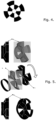
Fig 4 shows the splitter in the version with space for the culvert pipe in the front view, -
Fig 5 shows the connection of the pass and the rim into a layout forming a splitter, -
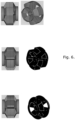
Fig 6 shows different connections of splitters in versions with and without diversion to the opposite pipe, -
Fig 7 shows splitters separated in a double containment piping system with reversal of the counter-flow streams of the casing pipe and inner pipe, in an isometric view, -
Fig 8 shows splitters in a reversed stream system with a channel pipe (e.g., by-pass) and metallised foil wound around the rim as a function of the foil heat exchanger, in an isometric view, -
Fig 9 shows the splitters in a reverse stream system with a culvert pipe (e.g., by-pass), in a side view -
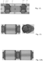
Fig 10 shows splitters with a culvert pipe (e.g., by-pass) and metallised foil wound around the rims in the function of a foil heat exchanger, longitudinal section, -
Fig 11 shows splitters in a system with diverting streams and a rectilinear counterflow heat exchanger with fold markings (alternating channels) with metallised foil wound around the rims in the function of a disposable heat exchanger, a side view, -
Fig 11a shows splitters in a reversed stream system and a heat exchanger in the form of metallised foil wound around the rim in the function of a disposable heat exchanger with the rotation of each splitter on the culvert pipe to achieve a torsion of the channels advantageous for temperature transmission, in a side view, -
Fig 12 shows a double-contained pipe system with splitters and a double containment pipe between the splitters with the function of reversing the counterflow streams of the casing pipe with the inner pipe and conversely, in a side view, -
Fig 13 shows the splitters in a reversed stream system and with metallised film wound around the rim in the function of a heat exchanger with rim-driven (rim-driven) fans attached to the flanges and double suction impellers, in a side view, -
Fig 13a shows splitters in a system of two heat exchangers separated by a rim-driven (rim-driven) fan attached to flanges in the central part and a double suction impeller, with the exchanger on the left without diverting streams, the exchanger on the right with diverting streams, in side view, -
Fig 14 shows an example of connecting the components of an adjustable splitter, -
Fig 14a shows a close-up view of the flow limiter and the keyway connection allowing the splitter to be adjusted, -
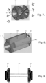
Fig 15 shows the exchanger-fan in a side view, -
Fig 15A shows the exchanger-fan in a front view, -
Fig 16 shows exchangers in a channel system made of metallic foil wound, rim-driven - a side view, -
Fig 16a shows the exchangers in a channel system made of metallic foil wound, rim-driven (rim-driven) - a front view, -
Fig 16b shows the exchangers in a channel system made of metallic foil wound, rim-driven (rim-driven) - an isometric view, -
Fig 17 shows a cross-flow fan exchanger installed in a stator, a side view, -
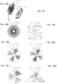
Fig 18 shows the shapes of the rim and channels of the exchanger, the casing pipe and the inner pipe determining the shape (outline) of the heat exchanger and channels:- 18a - splitters with a round shape having a visible rim,
- 18b - shape of a round splitter with a rim,
- 18c - rim shape of a square exchanger with channels attached to culvert pipe,
- 18d - rim shape of a round exchanger with channels attached to culvert pipe,
- 18e - rim shape of circular exchanger with channels shifted away from culvert pipe, ensuring stream flows between the folds,
- 18f - rim shape of hexagonal exchanger having a mosaic outline,
- 18g - rim shape of the triangular exchanger,
-
Fig 19 shows an example of combining exchangers into heat exchanger systems (square and hexagonal cross-section), -
Fig 20 shows an example of combining hexagonal exchangers into a heat exchanger system with a channel covering the surface of the casing pipe in a function of a collecting pipe, an isometric view, - The solution according to the invention is presented as an example of execution so as not to hinder the invention.
- The stream splitter for double-contained pipe systems, mixing of streams and heat exchangers has stream splitters (1) and (2) attached at both ends of the culvert pipe (6), which splitters have a flange (3). Between the splitters (1) and (2) around the culvert pipe (6), alternate plugs (10) and openings (11) of the channels are placed which form a triangular in profile rotary passage (4) of about one fold (channel) of the heat exchanger and a rim (5). The plugs and openings (10) and (11), together with the rim (5) leading out of them, form the heat exchanger (9). The air streams separated into internal and external ones relative to the inner pipe (7) of the double-contained pipe system, as a result of flowing through the stream splitter, are separated by alternating plugs and airflow openings outside the inner pipe (7) and conversely located plugs and openings inside the inner pipe (7). The stream splitters (1) and (2) located at opposite ends of the heat exchanger differ with a displacement of the inlet and outlet by one channel in such a way that the fluid inlet into the channel on the outside of the inner pipe is simultaneously plugged on the inside of the inner pipe, whereas on the other end the channel, it is open on the inside of the inner pipe and plugged on the outside of the inner pipe. The channel inlets and outlets are located alternately either on one side of the exchanger or another. Streams in an alternating system (supply and exhaust), by using the stream splitter (1) and (2) are redirected to the space of the inner pipe (7) and the casing pipe (8) (supply streams with supply streams and exhaust streams with exhaust streams). The culvert pipe (6) acts as a stiffener for the heat exchanger (9), and can also act as a by-pass or a culvert.
- In this solution, each plug and opening (10) and (11) is divided at the level of the stream splitter (1) and (2) into two parts - on the outside and inside the inner pipe (7). Each fold of the exchanger (12) is opened on one end by the stream splitter in the outer part of the inner pipe (7), whereas on the other end, it is opened by the splitter only in the inner part of the inner pipe (7). The plugs (10) of the channels at an angle relative to the direction of stream thrust cause the fluid flowing through the channels to be pushed toward the outlet at their ends. The heat exchanger (9) has folds (12) of the exchanger (channel closed on the side of the casing pipe).
- The splitters (1) and (2) are advantageously adjustable relative to one another. The movement of one splitter relative to the other is a shift by one fold, toward the following fold. This movement is advantageously limited since its continuation by more than one channel would result in a return to the previous position. The connection of all the elements can be made by clicking them on the keyway connection (groove) (13). Since the splitters (1) and (2) differ from each other by a displacement of the inlet and outlet by one channel - for the turning of the splitters to occur by one channel only, a turn stop is introduced (14) in the form of a rigid element (advantageously a tab), blocking further turning.
- The solution according to the invention made as in Example 1, with the difference that it has two stream splitters (1) connected by a culvert pipe (6). The two splitters (1) are installed on this pipe, and a flange (3) is placed on the outer side of each splitter. In the exchanger axis (9), folds (12) are placed between the splitters (1). These channels are alternately plugged and open (10) and (11).
- The solution according to the invention made as in Example 1, with the difference that it has two stream splitters (2) and no culvert pipe (6).
- The solution according to the invention made as in Example 1, with the difference that the triangular shape of the openings - alternate openings (10) and plugs (11) of the channels in each of the stream splitters (1) and (2) located at opposite ends of the pipe system, makes it possible to lead out the double contained pipe system for fastening the connection of the channels or fastening a motor with a traditional hub design, driven by a rim (so-called "rim-driven") or any other motor known in the state of the art. The motor is located advantageously between two exchangers (9). This design of the double exchanger with the fan located centrally between the exchangers (9) results in better silencing of the fan operation and temperature-stable operating conditions (compared to the fan, known in the state of the art, located in the furthest point of the outer side of the elevation).
- A stream splitter for double-contained pipe systems, mixing of streams and for heat exchangers has stream splitters (1) and (2) installed at both ends of the culvert pipe (6), which splitters have a flange (3). Between the splitters (1) and (2), around the culvert pipe (6), alternate plugs (10) and openings (11) of the channels are placed. The plugs and openings (10) and (11), together with the rim (5) leading out of them, form the heat exchanger (9). The channel inlets and outlets are located alternately, either on one side of the exchanger or another. Streams in an alternating system (supply and exhaust), by using the stream splitter (1) and (2) are redirected to the space of the inner pipe (7) and the casing pipe (8) (supply stream with supply stream and exhaust stream with exhaust stream). The culvert pipe (6) acts as a stiffener for the heat exchanger (9), as well as it may act as a by-pass or channel. Each fold of the heat exchanger (12) is opened on one end by a stream splitter in the outer part of the inner pipe (7), and is opened on the other end by a splitter only in the inner part of the inner pipe (7). The plugs (10) of the channels at an angle relative to the direction of stream thrust cause the fluid flowing through the channels to be pushed toward the outlet at the end of the channels. On the stream splitters (1) and (2), stream splitter blades (14) are installed, while on the backs of the folds (channels) (12), fan impeller blades (15) known in the state of the art as impeller blades are placed. The stiffening structure of the casing pipe (8) can be performed by a stator (16). The solution according to the invention has a drive known in the state of the art, e.g. rim-driven (17).
- Heat exchanger (9) constructed as in Example 5 with the difference that the rim (5) has a square shape in cross-section. The rim (5) in cross-section with a square shape determines the identical shape of the entire exchanger (9) and its channels (12). The fan exchanger shaped in this way is combined into exchanger sets.
- Heat exchanger (9) constructed as in Example 5 with the difference that the rim (5) has a triangular shape in cross-section. The rim (5) having a triangular shape in cross-section determines the identical shape of the entire heat exchanger (9) and its channels (12).
- The heat exchanger (9), constructed as in Example 5, has a rim (5) in cross-section with a hexagonal shape. This rim determines the identical shape of the entire exchanger (9) and its channels (12). The stream splitters (1) and (2) are installed on both ends of the centre pipe (6). Each of the stream splitters (1) and (2) has a flange (3). Between splitters (1) and (2), channels are placed around the central pipe (6), which have a rotary transition (4). Streams in an alternating system (supply and exhaust) by using stream splitters (1) and (2) are redirected to the space of the central pipe (6) and the casing pipe (8). Thus formed stream splitters (1) and (2), through the rim (5), are combined into sets with further stream splitters (2), and thus with another heat exchanger (9). After the exchangers are connected into sets, the channel covering (18) the surface of the casing pipes of the exchangers acts as a collecting pipe.
Claims (9)
- Stream splitter for double-contained pipe system, mixing and diverting streams and heat exchangers with fan heat exchanger and exchanger systems consisting of pipes, exchanger, channels and openings, characterised in that on the flange (3) in the shape of a circle or a shape adapted to the shape of the casing pipe (8), plugs and openings of channels (10) and (11) are located alternately to the inside and outside relative to the inner pipe (7), the number and shape of which correspond to the number and shape of the heat exchanger channels (9), with the inlet and outlet of each channel redirected to the outside and inside of the inner pipe (7); whereby the displacement by one fold (channel) of one of the two splitters causes the same channel to be open on one end in the outer part and simultaneously plugged in the inner part of the inner pipe (7), and open on the other end in the inner part and simultaneously plugged in the outer part of the inner pipe (7); whereby the plugs and openings of the channels (10) and (11) of the splitter are extended, advantageously aerodynamically, into a shape similar to a triangle/wedge, the inclination angles of the walls of which determine the stream thrust angle and determine the change in the thrust direction of streams in relation to their separation.
- Stream splitter for double-contained pipe system, mixing and diverting streams and heat exchangers with fan heat exchanger and exchanger systems according to claim. 1, characterised in that between the passage (4) and the rim (5) a displacement occurs relative to the longitudinal axis by one fold (channel) (12) of the heat exchanger relative to the rim (5).
- Stream splitter for double-contained pipe system, mixing and diverting streams and heat exchangers with fan heat exchanger and exchanger systems according to claim. 1 or 2, characterised in that they are installed on two sides of the heat exchanger or pipe system advantageously so that the splitters (1) and (2) located at opposite ends of the exchanger differ from each other by displacement of the inlet and outlet by one channel in such a way that the fluid inlet to the channel on the outer side of the inner pipe (7) is simultaneously plugged on the inner side of the inner pipe (7), and on the other end the channel it is open on the inner side of the inner pipe (7) and plugged on the outer side of the inner pipe (7); whereby the channel inlets and outlets are located alternately on one side of the counterflow heat exchanger or the other.
- Stream splitter for double-contained pipe system, mixing and diverting streams and heat exchangers with fan heat exchanger and exchanger systems according to claim. 1 or 2 or 3, characterised in that each channel is opened on one end by the stream splitter (1) and (2) in the outer part of the inner pipe (7), and on the other end, it is opened only in the inner part of the inner pipe (7), while on each end, each channel is partially open and partially plugged advantageously at an angle, thus fixing the inlet and outlet respectively to the inside or outside of the inner pipe.
- Stream splitter for double-contained pipe system, mixing and diverting streams and heat exchangers with fan heat exchanger and exchanger systems according to claim. 1 or 2 or 3 or 4, characterised in that the rim (5) enables the attachment, in a method known in the state of the art, of a metallic foil and other membrane with parameters (known in the state of the art) of a non-fixed shape that enable the formation and ensure the sealing and heat transfer of the foil heat exchanger.
- Stream splitter for double-contained pipe system, mixing and diverting streams and heat exchangers with fan heat exchanger and exchanger systems according to claim. 1 or 2 or 3 or 4 or 5, characterised in that on the stream splitters (1) and (2) located on the opposite side of the heat exchanger (9), stream splitter blades (14) are placed in the inner and outer parts of the inner pipe (7), while on the fold ridges (channels) (12) of the exchanger, fan impeller blades (15) known in the state of the art are placed, whereby the stream splitter blades (14) capture the streams and direct them to the exchanger channels; whereby the channel walls (12) of the heat exchanger (9) constitute also the fan impeller blades (15).
- Stream splitter for double-contained pipe system, mixing and diverting streams and heat exchangers with fan heat exchanger and exchanger systems according to claim. 1 or 2 or 3 or 4 or 5 or 6, characterised in that the stream splitter blades (14) and the fan impeller blades (15) are advantageously combined into a single blade.
- Stream splitter for double-contained pipe system, mixing and diverting streams and heat exchangers with fan heat exchanger and exchanger systems according to claim. 1 or 2 or 3 or 4 or 5 or 6 or 7, characterised in that, through the rim (5) and channels, the stream splitter (1) or (2) is combined with the opposite rim (5) and the stream splitter (1) or (2) to form a heat exchanger (9); whereby the heat exchanger (9), by combining the stream splitters (1) or (2) with each other, is combined with the following stream splitters (1) or (2) into heat exchanger systems.
- Stream splitter for double-contained pipe system, mixing and diverting streams and heat exchangers with fan heat exchanger and exchanger systems according to claim. 1 or 2, or 3, or 4, or 5, or 6, or 7, or 8, characterised in that the rim (5) of the heat exchanger (9) and the channels (12) of the heat exchanger may have a hexagonal shape in cross-section
Applications Claiming Priority (2)
| Application Number | Priority Date | Filing Date | Title |
|---|---|---|---|
| PL444747A PL444747A1 (en) | 2023-05-04 | 2023-05-04 | Flow divider for twin pipelines, flow mixing and redirection and heat exchangers |
| PL444994A PL444994A3 (en) | 2023-05-25 | 2023-05-25 | Stream distributor for double pipelines, for mixing and redirecting streams and heat exchangers with a fan heat exchanger and exchanger assemblies |
Publications (1)
| Publication Number | Publication Date |
|---|---|
| EP4471365A1 true EP4471365A1 (en) | 2024-12-04 |
Family
ID=93377558
Family Applications (1)
| Application Number | Title | Priority Date | Filing Date |
|---|---|---|---|
| EP24460017.7A Pending EP4471365A1 (en) | 2023-05-04 | 2024-04-15 | Stream splitter for double-contained pipe system |
Country Status (1)
| Country | Link |
|---|---|
| EP (1) | EP4471365A1 (en) |
Citations (5)
| Publication number | Priority date | Publication date | Assignee | Title |
|---|---|---|---|---|
| WO2008052493A1 (en) * | 2006-10-31 | 2008-05-08 | Josef Bachmaier | Compact fan, comprising a heat exchanger with integrated or attached ventilators |
| EP2754970A1 (en) * | 2011-09-08 | 2014-07-16 | Korea Institute Of Construction Technology | Hybrid ventilation apparatus capable of both natural and forced ventilation |
| WO2019017831A1 (en) * | 2017-07-21 | 2019-01-24 | Air To Air Sweden Ab | Coaxial flow distribution device |
| EP4083438A1 (en) * | 2021-04-29 | 2022-11-02 | Napalmi Tietotekniikka Oy | Double flow heat exchanging fan |
| CZ37536U1 (en) * | 2023-10-12 | 2023-12-01 | Recutech S.R.O. | A countercurrent cylindrical recuperative heat exchanger, intended for ventilation of buildings |
-
2024
- 2024-04-15 EP EP24460017.7A patent/EP4471365A1/en active Pending
Patent Citations (5)
| Publication number | Priority date | Publication date | Assignee | Title |
|---|---|---|---|---|
| WO2008052493A1 (en) * | 2006-10-31 | 2008-05-08 | Josef Bachmaier | Compact fan, comprising a heat exchanger with integrated or attached ventilators |
| EP2754970A1 (en) * | 2011-09-08 | 2014-07-16 | Korea Institute Of Construction Technology | Hybrid ventilation apparatus capable of both natural and forced ventilation |
| WO2019017831A1 (en) * | 2017-07-21 | 2019-01-24 | Air To Air Sweden Ab | Coaxial flow distribution device |
| EP4083438A1 (en) * | 2021-04-29 | 2022-11-02 | Napalmi Tietotekniikka Oy | Double flow heat exchanging fan |
| CZ37536U1 (en) * | 2023-10-12 | 2023-12-01 | Recutech S.R.O. | A countercurrent cylindrical recuperative heat exchanger, intended for ventilation of buildings |
Similar Documents
| Publication | Publication Date | Title |
|---|---|---|
| CN107208985B (en) | Heat exchangers and air technology plants with heat exchangers | |
| EP4185821B1 (en) | Heat recovery unit | |
| US20230175786A1 (en) | Exchanger device | |
| EP0511594A1 (en) | Impeller in water pump | |
| RU2711903C2 (en) | Complex system of fan and heat exchanger | |
| JPS6081579A (en) | Disk type flow distributing valve | |
| US4685443A (en) | Hydraulic friction heat generator | |
| US4073338A (en) | Heat exchangers | |
| CN106677980A (en) | Blade device for wind power generation | |
| JP2020523546A (en) | Plate and shell heat exchange system with split manifold tubes | |
| FI3271676T3 (en) | Exchange element for passenger cabin and passenger cabin equipped with such an exchange element | |
| JPH07279892A (en) | Multi-wing fan | |
| JPH0772640B2 (en) | Counter-rotating ventilation | |
| GB2439557A (en) | A heat exchanger and heat exchanger assembly | |
| EP0586402B1 (en) | Method and device for transfer of heat or mass | |
| CN210087660U (en) | Turbine and building ventilation systems with casings | |
| KR100787227B1 (en) | Multi-directional fluid induction fan, fluid circulation method and heat exchange method using the same | |
| CN118548743A (en) | Dispenser | |
| US20090321051A1 (en) | Method and means for pumping in heat exchange applications | |
| JPH0741907Y2 (en) | Reversible screw pump | |
| JP4413525B2 (en) | Cross-flow fan wheel | |
| US3295597A (en) | Heat exchangers | |
| US20210025399A1 (en) | Water pump module | |
| CN117514380B (en) | Water capturing device of steam turbine and steam turbine | |
| RU2004856C1 (en) | Wave pressure exchanger |
Legal Events
| Date | Code | Title | Description |
|---|---|---|---|
| PUAI | Public reference made under article 153(3) epc to a published international application that has entered the european phase |
Free format text: ORIGINAL CODE: 0009012 |
|
| STAA | Information on the status of an ep patent application or granted ep patent |
Free format text: STATUS: THE APPLICATION HAS BEEN PUBLISHED |
|
| AK | Designated contracting states |
Kind code of ref document: A1 Designated state(s): AL AT BE BG CH CY CZ DE DK EE ES FI FR GB GR HR HU IE IS IT LI LT LU LV MC ME MK MT NL NO PL PT RO RS SE SI SK SM TR |
|
| STAA | Information on the status of an ep patent application or granted ep patent |
Free format text: STATUS: REQUEST FOR EXAMINATION WAS MADE |
|
| 17P | Request for examination filed |
Effective date: 20250313 |
|
| STAA | Information on the status of an ep patent application or granted ep patent |
Free format text: STATUS: EXAMINATION IS IN PROGRESS |
|
| 17Q | First examination report despatched |
Effective date: 20251009 |