-
The invention relates to a primary optic for homogeneously illuminating a cover of a luminaire, and such a luminaire. The primary optic hereby is designed to mimic light emission of a fluorescent lamp, resulting in an utmost homogeneous light emission in all directions and thus achieving a homogeneously illumination of a cover of a respective luminaire. Hereby the cover of the luminaire forms the light emitting surface(s) of the luminaire. The primary optic created in this way is configured and designed to be used in particular in luminaires with an extremely small distance (only around 30 mm) between the LED circuit board of the luminaire, which is mounted on the gear tray of the luminaire and the light emitting surfaces of the cover of the luminaire, while still achieving an illumination of all sides of the cover, which has a - compared to the distance between the gear tray and the cover - relatively huge width (around 140 mm) and height (around 55 mm) that is perceived as homogeneous, uniform and pleasant for the human eye. With this configuration compact luminaires with LEDs as light sources can be obtained, whereas the favorable light characteristics of fluorescent tubes is still achieved.
-
With the use of commonly known lenses in such a tight configuration of the luminaire with regard to the distances in-between the LED circuit board and the surfaces of the cover of such a luminaire, would create a non-uniform illumination, such as stripes of different brightness, in the center of the cover and/or at sides of the cover that would make the appearance of the luminaire unpleasant for the human eye, and thus disadvantageous.
-
The document
WO 2011/032975 A1 shows an LED luminous element for illuminating a light box having homogeneous light distribution and thus targets a similar application, providing a luminaire and an optical element, which shall be used in lighting applications wherein fluorescent tubes are commonly used. Hereby a light source mounted on a printed circuit board is placed within a recess of a unit, wherein the unit consists of a lens and a carrier element. Additionally, side walls can be mounted on the carrier element whereas these side walls form light diffusions. The such formed luminaire element is then placed on a side wall of a luminaire housing, in between a plate like and translucent front side and an at least partially reflective plate like back side of the housing. Compared to the dimensions of the lighting element, the front and back side of the luminaire are relatively large in scale, such that the light element and its lens is positioned far away from the central portion and the opposite end portion of the front and back sides of the luminaire.
-
Thus, the invention is therefore concerned with the task of providing a primary optic for a luminaire, in which the primary optic achieves a homogeneous and uniform illumination of the cover of the luminaire.
-
According to the invention, the primary optic for homogeneously illuminating a cover of an elongated luminaire comprises a central lens component and two laterally arranged ridges, and all components of the primary optic are integrally connected to each other, whereas the primary optic is made of a clear material with diffusion scattering elements. Hereby the central lens component has a convex lens surface that has a large radius of curvature. Furthermore, the central lens component has a recess, whereas the recess forms a light source receiving space in which a light source of a luminaire can be arranged. Hereby, the light source is an LED placed on an elongated LED circuit board of the luminaire. Moreover, the afore mentioned recess forms a lens inner surface, wherein the lens inner surface has a central concave curvature with a small radius of curvature. Additionally, the lateral ridges are deposed on two opposite sides of the central lens component and extend substantially parallel to a central axis of the primary optic, wherein the lens surface is posed between the lateral ridges.
-
The such configured primary optic with its characteristic structures and especially its clear material with diffusing scattering elements work together synergistically, providing an utmost homogeneous light emission of the primary optic respectively of the inserted light emitted from a respective light source of the luminaire. Hereby, the convex lens surface of the central lens component provides the main part of a downward phased light emission of the primary optic, whereas the laterally arranged ridges provide lateral light emission, wherein it even is possible to illuminate portions of the cover of the luminaire which are arranged in an opposite direction with regard to the light emission direction of the light source of the luminaire and placed above the light source viewed in a cross section perpendicular to the longitudinal axis of the primary optic, or respectively for luminaire.
-
Hereby preferably the curvature of the central lens component may not only be described by the radius but additionally by a conic constant and polynomial terms that shape the lens. With regard to the central curvature it is preferably to be stated, that this curvature may be described by a parabola function y(x) - with the parameters
a and
b being parameters that define the parabolas shape, and c as a constant offset - as expressed below:
-
Further, the luminaire itself is embodied herein whereas the luminaire comprises a ceiling mount; a carrier element; a cover; an elongated LED circuit board, with LEDs as a light source placed on a printed circuit board, PCB; and a primary optic according to a herein presented embodiment of the above-mentioned primary optic. Hereby the carrier element is arranged on the ceiling mount, whereas the PCB as well as the primary optic is arranged on the carrier element. Furthermore, the light source is arranged in the recess of the primary optic, wherein the cover is placed on the ceiling mount, thus forming an interior space in which the carrier element together with the elongated LED circuit board and the primary optic is arranged.
-
With the arrangement of the carrier element inside the luminaire and the primary optic placed on it, it is achieved that the primary optic is located close to the center of the interior space created by the cover, and therefore parts of the cover are not illuminated by the light source per se, if the primary optic is not present. However, due to the primary optic formed in such a way, it is achieved that the light emitted by the light source is deflected efficiently and on a short path in all directions, and thus a homogeneous light emission of the primary optic and thus also a particularly homogeneous illumination of the cover of the luminaire is achieved. This also results in particularly advantageous light emission from the luminaire via its cover.
-
Optionally at least one surface of each of the two ridges comprises optical elements, such as lenticular structures for dispersive light extraction. With such a configured lateral ridge light extraction and thus light emission of the primary optic is further improved, providing an improved homogeneous light extraction. Hereby these optical element further support a light extraction in a direction opposite to the light emission direction of the light source of the luminaire, achieving that portions of the cover of the luminaire which are arranged counter to the light emission direction of the luminaire are also illuminated, and therefore forming a particular beneficial light distribution on these sides of the cover.
-
Optionally, the lens inner surface further comprises two lateral concave curvatures having a larger radius of curvature than that of the central curvature, wherein preferably the lateral curvatures are arranged mirror symmetrically with respect to the central axis at the sides of the central curvature. With these two lateral concave curvatures and the central concave curvature the recess of the primary optic, respectively of the central lens component of the primary optic, is enlarged resulting in a bigger light source receiving space. This additional space inside the primary optic is particularly advantageous in scenarios where besides the LED light sources other electronic components are placed on the elongated LED circuit board of the luminaire. Hereby, e.g.: connecting parts, switches, or the like can be mounted on the printed circuit board allowing for a flush positioning of the printed circuit board towards the carrier element, as these elements are arranged on the opposite side of the PCB facing the primary optic. Furthermore, the lateral concave curvatures affect the light distribution inside the primary optic, whereas these lateral concave curvatures promote a higher fraction of light beams directed to the lens surface of the central lens component, and thus a higher fraction of light emitted downwardly from the optical element.
-
Hereby it is worth noting that the scattering particles in the material of the primary optic the scattering particles of the material of the primary optic counteract this actual light distribution of the lateral curvatures, so that the light distribution favoured by the lateral curvatures is weakened in the direction of the lens surface of the central lens component, and a homogeneous light distribution to the side areas of the primary optic is achieved. Therefore, with the synergistic effects of the material and the lateral curvatures, space within the primary lens is gained, while upholding the preferred light distribution towards the lens surface of the central lens component as well as the lateral surfaces of the primary lens. Depending on the choice of the proportion of scattering particles, the light distribution of the primary optic can be individualised.
-
In another implementation, e.g. implementations where the additional room of the recess formed by the two lateral concave curvatures is not needed, as besides the LED light sources no other electrical elements are to be placed on the elongated LED circuit board, it is also conceivable to solely have one central curvature with a small radius of curvature resulting in a strong curvature. With this implementation even more light could be directed towards lateral surfaces of the primary optic, such as the ridges. This would lead to a higher fraction of emitted light being directed towards side surfaces of the cover.
-
Further preferred the light source placed in the light source receiving space is disposed within the depth of the recess formed by the two lateral concave curvatures. With this implementation it is achieved that the full height of the recess is used with a maximum length of being a surface being directly illuminated by light emitted from a respective light source placed in the light source receiving space. In implementations where the two lateral concave curvatures are not needed and thus only the central concave curvature is present, the light source shall be placed centered in an end area of the central curvature, wherein that end portion of the central curvature is at the opposite end of the curvature from the apex of the curvature. This again results in an effective usage of the full height of the recess and a corresponding maximum length of the inner surface being directly illuminated by light emitted from the light source.
-
Optionally, the lateral ridges are each coupled to the central lens component below the respective lateral curvature but above the apex, i.e., the low point, of the central curvature. This configuration leads to a particularly advantageous light distraction within the primary optic towards the lateral ridges, improving lateral light emission of the primary optic. Further preferred and generally speaking, the lateral ridges shall be coupled to the central lens portion laterally and at half height of the recess.
-
Optionally, each lateral ridge has an inner facing surface, which is arranged on a side of the respective ridge facing the respective other ridge, and an outer facing surface, which is arranged on a side of the respective ridge facing away from the respective other ridge. With this implementation homogenous light distribution is further improved, whereas with the inner facing surfaces facing each other with the lens surface in between, a synergistic improved light guidance is achieved. Preferably, the inner facing surface and/or outer facing surface of a ridge has lenticular structures for dispersive light extraction. With these lenticular structures as optical elements on a side surface of the respective ridge, light extraction is further improved, whereas it is also conceivable that these lenticular structures form a secondary effect, further providing on the respective sides facing the lens surface an improved light re-insertion inside the respective ridge from the lens surface to achieve better lateral light emission of the primary optic. Further, preferably the respective same surfaces of the lateral ridges are formed identically. This improves symmetric light emission of the primary optic and thus improves homogeneous light emission of the luminaire.
-
Optionally, the lateral ridges project beyond the lens surface in light emission direction parallel to the central axis. With this implementation, the portion of light beams being emitted by the lens surface of the central lens portion and being re-inserted in the lateral ridges is further improved. Furthermore, this results in an improved light emission of the primary optic in a direction opposite to the light emission direction of the light source of the luminaire.
-
Optionally, the central lens component comprises a base part, which is arranged on a side of the central lens component opposite to the lens surface and forms the base of the primary optic. With this base part the primary optic is contacted with the carrier element of the luminaire. Preferably, the base part has lateral flange elements viewed in cross section perpendicular to the longitudinal axis of the primary optic. These flange elements on the opposite side of the primary optic compared to the lens surface further improve light emission towards a lateral side of the primary optic. Further, preferably between each lateral ridge and a flange element arranged on the associated side, an indentation is provided in the primary optic, which separates the respective flange element and the respective ridge from each other. With this indentation light emission and reflection on the lateral side of the primary optic is improved. Even further preferred the flange element has coupling elements, in particular latching hooks, for coupling with the carrier element of the luminaire. This provides a particular easy and stable connection between these two elements of the luminaire.
-
Optionally the primary optic is formed substantially mirror symmetrical to the central axis. With this implementation the primary optic has a further favorable homogeneous light distribution with regard to a symmetrical light emission.
-
Optionally the central lens component has a circuit board notch for inserting a printed circuit board, PCB, of the luminaire. This further facilitates assembly of the luminaire. Furthermore, this allows for a slim height of the luminaire, as the PCB and its components mounted thereon are easily received within the primary optic. Hereby the circuit board notch is arranged such that the recess is closed by the inserted board viewed in a cross-section perpendicular to the longitudinal axis of the primary optic. This further eases installation of the primary optic on the luminaire.
-
Optionally the recess projects far into the central lens component in the region of the central curvature, and hereby preferably has a depth of more than 60%, further preferably more than 70%, particularly preferably more than 75% of the height of the primary optic. This increases the surface area of the lens inner surface due to the strong curvature, which also increases the area for maximum light deflection and thus improves the dispersion towards the lateral areas of the primary optic in particular.
-
Optionally the primary optic has a height of about 20 mm, preferably of about 16 mm. This allows for a slim design of the luminaire, increasing applicability of the primary optic.
-
Optionally the primary optic has a width of approximately 45 mm. The primary optic thus formed can easily be placed in various luminaires do to its slim design.
-
Optionally the primary optic is created by extrusion. This implementation achieves an utmost simple design, whereas a unitary light distribution of the primary optic along its longitudinal axis is obtained. Furthermore, production costs are decreased while simultaneously allowing for primary optics in individual lengths, depending on the respective lighting scenario.
-
Optionally the primary optic is made of polymethylmethacrylate, PMMA, with diffuse scattering particles. This material is favorable as it is price attractive, durable, and has advantageous light deflection characteristics paired with the scattering particles.
-
Optionally the primary optic and the carrier element have substantially the same width, resulting in an utmost slim design of the luminaire. Furthermore, as the carrier element does not overlap the primary optic, light emission towards areas above the primary optic and besides the carrier element (such as the lateral surfaces or the front surfaces of the cover) are possible as the carrier element does not block any laterally emitted light of the primary optic.
-
Optionally the primary optic and the carrier element are flush against and abut each other. This improves light reflection characteristics at the connecting edge, improving light diffusion and light guidance inside the primary optic.
-
Optionally the primary optic is disposed on an outer base surface of the carrier element. This eases installation of the luminaire and further allows for a positioning of the primary optic within the luminaire which is similar to conventional luminescent tubes.
-
Optionally the PCB is sandwiched between the primary optic and the carrier element. This further improves installation and achieves a steady placement, preventing displacements of the PCB, and thus the light source, allowing for an optimal light insertion into the primary optic.
-
Optionally the cover is formed of a translucent matte material. This further improves light diffusion, and achieves an utmost homogenous and aesthetic light emission of the luminaire.
-
Optionally the cover is cuboid-shaped, improving aesthetics and resulting in a luminaire design similar to conventional luminaires with luminescent tubes. Hereby preferably the cover has a lower surface, two lateral surfaces extending along the longitudinal axis of the luminaire, and a respective front surface at each longitudinal end of the luminaire. Whereas further preferred at least one of these surfaces of the cover is a light-emitting surface. Optionally the width of the cover is approximately 140 mm and the height of the cover is approximately 55 mm, resulting in a slim design of the luminaire with typical dimensions of conventional luminaires with luminescent tubes.
-
Optionally a first distance between the surface of the primary optic facing the carrier element and the lower surface of the cover is approximately 30 mm; and/or a second distance between a front end of the primary optic and the respective front surface of the cover is approximately 30 mm. This results in an utmost compact luminaire with little distance between the primary optic and the cover.
-
The invention is explained in detail below with reference to examples of embodiments and with reference to the drawings. The figures show:
- Figure 1
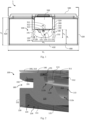
- Side view of an exemplary embodiment of a luminaire according to the invention, with an exemplary embodiment of a primary optic according to the invention viewed in a cross-section perpendicular to the longitudinal axis of the luminaire or of the primary optic, respectively;
- Figure 2
- Enlarged oblique view of a cross section perpendicular to the longitudinal axis of an exemplary embodiment of a luminaire according to the invention in the region of the primary optic and the LED circuit board;
- Figure 3
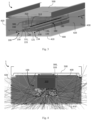
- Oblique view of an exemplary embodiment of a luminaire according to the invention with a cover shown in transparent form and a carrier element shown in transparent form;
- Figure 4
- Light beam path within an exemplary embodiment of a luminaire according to the invention with an exemplary embodiment of a primary optic according to the invention;
- Figure 5
- Angled view of an exemplary embodiment of a luminaire according to the invention in the installation state of the luminaire with the cover removed;
- Figure 6
- Angled view of an exemplary embodiment of a luminaire according to the invention in the operating state of the luminaire;
- Figure 7
- Light distribution curve of an embodiment of a luminaire according to the invention, without an attached cover;
- Figure 8A -
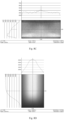
- 8D Light intensity curves of different areas of the cover of an exemplary embodiment of a luminaire according to the invention with an exemplary embodiment of a primary optic according to the invention.
-
Figures 1 to 4 show different views and representations of the same embodiment of the luminaire 1 according to the invention or the same embodiment of the primary optic 100 according to the invention. Features which are described below for certain figures can therefore also be read on the respective other figures. Figure 4 shows a light beam path of the luminaire 1 and in particular the light diffusion within the primary optic 100. Figures 5 and 6 schematically show the assembly of a luminaire 1 with a schematic representation of an embodiment of a primary optic 100 according to the invention, whereby Figure 5 shows the luminaire 1 in the installation state, i.e. with the cover 400 removed, and Figure 6 shows the luminaire 1 in the operating state, i.e. with the cover 400 fitted. Figure 7 shows the characteristic light distribution curve of an embodiment of a luminaire 1 according to the invention, without cover 400 attached (see Figure 5), i.e. essentially the light distribution curve of a light source 312 with an embodiment of a primary optic 100 according to the invention from the previous figures. Figures 8A, 8B, 8C and 8D show illumination curves at different positions of an embodiment of a luminaire 1 according to the invention, for example the luminaire 1 of Figure 6 with an embodiment of a primary optic 100 according to the invention from the previous figures.
-
Figure 1 shows an exemplary embodiment of a luminaire 1 according to the invention with an exemplary embodiment of a primary optic 100 according to the invention in a cross section perpendicular to the longitudinal direction L of the luminaire 1, respectively of the primary optic 100. Hereby the luminaire 1 comprises a ceiling mount 500, for mounting the luminaire 1 on a ceiling or a wall.
-
The carrier element 300 is hereby substantially U-shaped having a base surface 310 and on the two sides of the base surface 310 respective sides surfaces 320, forming a receiving space for operating devices 330 and/or control devices 330 of the luminaire 1. Hereby the base surface 310 is placed on a side opposite to the connection with the ceiling mount 500 of the carrier element 300. On an outer surface of the base surface 310, the LED circuit board formed by the printed circuit board, PCB, 311 and the light source 312, which is an LED 312, is placed. In the presented embodiment of the luminaire 1, and thus the primary optic 100, the LED circuit board further comprises other electrical components 313. The PCB 311 is hereby positioned flushed against the outer surface of the base surface 310 of the carrier element 300.
-
Sandwiching the PCB 311, the primary optic 100 is also placed on the outer surface of the base surface 310 of the carrier element 300, whereas the PCB 311 is positioned in a circuit board notch 170 of the primary optic 100, which is designed to receive respective PCB 311 of the luminaire 1. Hereby, the circuit board notch 170 is arranged such that the recess 110 is closed by the inserted board 311 as shown in the cross section perpendicular to the longitudinal axis L of the primary optic 100 with regard to figure 1. The such arranged primary optic 100 therefore also receives the light source 312 in its light source receiving space formed by the recess 110. The light source 312 is further arranged on a central axis M of the primary optic 100. In the embodiments shown, the light source 312 of the luminaire 1 is formed by a single LED array having a plurality of LEDs 312 arranged in a mutual line.
-
The light source 312 is hereby placed within the recess 110 of the primary optic 100, and hereby in particular placed on an upper end of the recess 110, which faces the PCB 311. The light source 312 is hereby disposed within the depth of the recess 110 formed by the two lateral concave curvatures 112b, as can be seen from Figure 1. The additional electronic component 313 is also placed within the depth of the recess 110 formed by the two lateral concave curvatures 112b, such that no elements are positioned within the recess 110 at a depth between the lateral concave curvatures 112b and the central concave curvature 112a.
-
As also illustrated in Figure 1, the central concave curvature 112a has a small radius, and thus the strongest bending, resulting in an utmost broad light refraction in a direction perpendicular to the middle axis M.
-
The lateral curvatures 112b has a larger radius of curvature, and thus a less strong bending, compared to the central curvature 112a. As a result, the light emitted by the light source 312 reaching this upper area of the lens inner surface 111 is deflected less strongly in the direction perpendicular to the center middle axis M - however, these lateral curvatures 112b result in a larger recess 110 and thus allow additional electronic components 313 to be accommodated therein. The lateral curvatures 112b are arranged mirror-symmetrically with respect to the central axis M at the sides of the central curvature 112a. On each side of the recess 110a, the two concave curvatures 112a, 112b are connected by a convex curvature 112c, which in the displayed embodiment almost forms a plateau like shape before transitioning into the respective concave curvatures 112a, 112b. Hereby the convex curvature 112c has a similar radius of curvature compared to the lateral curvature 112b. Preferably the curvatures 112a, 112b, 112c are all symmetrically shaped with regard to the middle axis M.
-
The central lens component 120 has a convex lens surface 121 on its outer side, which has a large radius of curvature and thus an extremely small curvature. This convex lens surface 121 is much wider than the inner recess 110 at its widest point. Lateral to this convex lens surface 121, as seen in cross-section in Figure 1, are lateral ridges 130, which are connected to the lens component 120 at approximately the mid-height of the primary optic 100. Thus, as shown in the Figures 1 to 4 the lateral ridges 130 are each coupled to the central lens component 120 below the respective lateral curvature 112b but above the low point of the central curvature 112a. With regard to the convex curve 112c it is to be stated that in the shown exemplary embodiments the coupling of the ridges 130 is below the plateau shaped surface formed by the convex curvature 112C.
-
The primary optic 100 and the carrier element 300, also known as gear tray 300, are arranged in the luminaire 1 together in an inner space formed by the cover 400. The cover 400 is essentially cuboid-shaped and is placed on the ceiling mount 500 like a box and connected to it. The cover 400 here essentially comprises five surfaces 410, 420, 430, which form the box-like structure of the cover 400. The cover 400 has a lower surface 410, two lateral surfaces 420 extending along the longitudinal axis L of the luminaire 1, and a respective front surface 430 at each longitudinal end of the luminaire 1. In the exemplary embodiments shown, all surfaces 410, 420, 430 of the cover 400 are light emitting surfaces. The lower main light emitting surface is formed by the lower surface 410, with the lens surface 121 of the central lens component 120 facing it. Each lateral ridge 130 is arranged facing one of the two lateral surfaces 420 running parallel to the longitudinal axis L. The front of the cover 400 is closed off by the front surfaces 430 at the respective ends of the luminaire 1.
-
In the preferred embodiment, the cover 400 has a width wC of about 140 mm and a height hC of about 55 mm, preferably about 50 mm. In contrast, in one embodiment, the primary optic 100 has a height hO of about 20 mm, preferably about 16 mm, and a width wO of about 45 mm.
-
These dimensions are common for luminaires used to illuminate workplaces, warehouses, corridors and similar environments, i.e. in scenarios which were previously predominantly illuminated by fluorescent tubes, whereby this in turn means considerable limitations with regard to the space available in the luminaire 1. This available space is further limited by the arrangement of the carrier element 300 with its operating and/or control devices 330 in the receiving space of the cover 400, whereby in addition an advantageous illumination of the cover 400 is impeded by the arrangement of the light source 312 substantially in the center of the luminaire 1 caused thereby. By means of the primary optic 100 according to the invention, or an embodiment thereof, an advantageous light intensity distribution at the sides 410, 420, 430 of the cover 400 is nevertheless achieved, which is shown in particular in figures 8A to 8D.
-
This achieved intensity distribution of the primary optic 100 is remarkable in that the distance d1 (also referred to as first distance d1) between the carrier element 300 - or its base surface 310, on which the primary optic 100 and the LED circuit board are arranged - and the lower surface 410 is only about 30 mm, preferably even only about 28,5 mm. The distance between the outer edges of the primary optic 100 and the lower surface 410 is thus extremely small, and in the case of the above-mentioned design of the primary optic 100 only about 10 mm, or 8,5 mm (with the primary optic having a height hO of about 20 mm), respectively 14 mm or 12,5 mm (with the primary optic having a height hO of about 16 mm). Also, the distance between the outer-facing surfaces 132 of the lateral ridges 130 and the respective lateral surface 420 of the cover 400 is thus only about 47.5 mm in each case. Furthermore, it is to be mentioned in the shown embodiment of the luminaire 1 with regard to the distance of the primary optic 100 to the front surfaces 430 of the cover that this distance d2 (also referred to as second distance d2) is only about 30 mm. This close spatial relationship between primary optic 100 and the available space formed by the cover 400 is illustrated in particular in Figure 3. Here, the carrier element 300, including the PCB 311 arranged thereon and any other electronic elements 313 arranged thereon, is shown transparently, so that the focus of this illustration is on the arrangement of the LEDs 312, the primary optic 100 and the arrangement within the cover 400.
-
As can be seen from Figures 1 to 5, the primary optic 100 is preferably mirror-symmetrical, with the central axis M of the primary optic 100 forming the mirror axis. This is particularly advantageous for homogeneous light emission. As can also be seen from Figures 1, 3, 4, 5 and 6, the luminaire 1 with its structural components is also essentially mirror-symmetrical, likewise with respect to the center axis M.
-
The primary optic 100 is designed in such a way that, despite its small dimensions and its small distance from the inner sides of the surfaces 410, 420, 430 of the cover 400, it illuminates the individual surfaces 410, 420, 430 particularly advantageously homogeneously and with uniform intensity distribution characteristic. In particular, the primary optic 100 achieves that parts of the lateral surfaces 420 and parts of the front surfaces 430, which (viewed in cross-section perpendicular to the longitudinal axis L; see Figures 1 and 4) are arranged above the light source 312, are nevertheless illuminated. This also becomes apparent when looking at the light distribution curve of the primary optic 100 in Figure 7. This shows - in addition to the obvious predominantly downwardly directed light emission both in C180 | Co, as well as C270 | C90 - also an upwardly directed light emission in C180|Co (see thicker curve) in the range between 90° and approximately 150°, whereby also the above mentioned partial areas of the lateral surfaces 420 and front surfaces 430 are illuminated - as described below with regard to Figures 8B and 8C. As the light distribution curve of Figure 7 also shows - and this is also indicated in the representation of the light beam paths of Figure 4 - the primary optic 100 thus created has a particularly broad light beam dispersion (fanning), whereby all surfaces 410, 420, 430 of the cover 400 are illuminated. The highest luminous intensity (approximately 370 candela) is achieved in the lateral area, in particular between 45° and 60°, whereby in particular lower edge areas and corner areas of the cover 400 of the luminaire 1 are sufficiently illuminated to achieve the most homogeneous light output possible. The illumination of the surfaces 410, 420, 430 of the cover is shown in particular in the illustrations of figure 8 (partial figures 8A to 8D).
-
In the embodiment shown, the lateral ridges 130 are essentially rectangular in cross-section perpendicular to the longitudinal axis L of the primary optic 100 and are coupled to the central lens component 120 via a short, relatively thin bridge running perpendicular to the central axis M of the primary optic 100. The lateral ridges 130 thus have two side surfaces 131, 132 running parallel to the longitudinal axis L and aligned substantially parallel to the central axis M, via which the decisive light influence of the lateral ridges 130 takes place. In the shown preferred embodiment the lateral ridges 130 each are basically arranged perpendicular to the central lens component 120. Hereby each lateral ridge 130 has an inner-facing surface 131, which is arranged on a side of the respective ridge 130 facing the respective other ridge 130, and an outer-facing surface 132, which is arranged on a side of the respective ridge 130 facing away from the respective other ridge 130.
-
As shown in particular in Figure 2, the inner-facing surface 131 can have optical elements 133, and in particular lenticular structures 133, which improve the light extraction from the lateral ridge 130. These lenticular structures 133 run parallel to the longitudinal axis L of the primary optic 100.
-
Alternatively or additionally, the optical elements 133 can be arranged on the outer-facing surface 132 opposite the inner-facing surface 131. In particular, both the optical elements 133 on the inner-facing surface 131 and the optical elements 133 on the outer-facing surface 132 can be designed to decouple light from the lateral ridge 130 via the outer-facing surface 132, so that overall lateral light emission from the primary optic 100 is improved. However, in another embodiment, it can also be provided that the optical elements 133 at least partially promote a central light emission of the primary optic, whereby this can be designed depending on the respective individual lighting requirements.
-
Also shown in Figures 1 and 2, the recess 110 with its curved inner surface 111 is designed in such a way that the components 312, 313 arranged on the PCB 311 have sufficient available space. This allows the PCB 311 to be arranged in direct contact with the carrier element 300 on the outer surface of the base surface 310, and the primary optic 100 to be arranged in direct contact therewith. This also favors a particularly flat and compact design of the coupling between the primary optic 100 and the carrier element 300 and thus of the luminaire 1 as a whole.
-
These lateral ridges 130 form a kind of corridor 134 in which the convex lens surface 121 is arranged. In the shown embodiment the lateral ridges 130 extend in a wall like manner from the central lens component 120. Due to the lateral arrangement and the alignment of the ridges 130 essentially parallel to the central axis M, a particularly advantageous light distribution and lateral light emission is achieved. With this lateral arrangement, it is achieved that in particular light beams which are initially emitted from the central lens component 120 in a lateral region of the lens surface 121 are either reflected at the lateral ridge 130, and thus contribute to a light emission via the lower surface 410 of the cover 400, or are also coupled back into the respective lateral ridge 130, whereby a light emission towards the lateral surfaces 420, 430 of the cover 400, and here in particular towards the respective lateral surface 420, is favored. The behavior of the respective lateral ridge 130 can be influenced and controlled by its surface properties and in particular by optical elements 133 arranged thereon, such as lateral ridges 133.
-
The lateral ridges 130 also define the height hO of the primary optic 100, as well as - together with the flange element 191 of the base part 190 - the width wO of the primary optic 100. In this respect, it can be provided that the lateral ridges 130 project beyond the lens surface 121, i.e. have a smaller distance to the lower surface 410 of the cover 400 than the lens surface 121.
-
The base part 190 serves as a contact element for the carrier element 300, whereby the PCB notch 170 for mounting the LED circuit board is also arranged in the central area of the base part 190 of the central lens component 120. In the peripheral area of the base part 190, the base part 190 features flange elements 191, which form laterally protruding elements of the central lens component 120. There is an indentation 170 between these flange elements 191 and the respective adjacent lateral ridge 130, which separates these two elements of the primary optic 100 from each other.
-
In a particular embodiment, the flange element 191 may have coupling elements 192 for coupling the primary optic 100 to the carrier element 300. In the shown embodiments of the primary optic 100, this can be done in particular by a latching hook 192, which interacts with corresponding latching spring elements and thus couples the primary optic 100 to the carrier element 300. This separation via the indentation 170 is intended to improve lateral light extraction and in particular advantageous lateral light distribution, as can be seen in particular from the light beam path shown in Figure 4.
-
The light emitted by the light source 132 and coupled into the primary optic 100 at the inner surface 111 is then - depending on the deflection by the corresponding section of the inner surface 111, or its curvature 112a, 112b, 112c - directed in the direction of the lens surface 121 of the lens component 120, or laterally in the direction of the lateral ridges 130 or the base part 190 and its flange element 191. In this case, there is already an extremely strong light mixing and homogeneous light distribution by the material of the primary optic 100 with its diffusing scattering elements. This is particularly evident in the exemplary light beam distribution shown in Figure 4.
-
As shown in all figures, the primary optic 100 is formed in one piece, so that all components such as central lens component 120, and its base part 190, as well as the lateral ridges 130 are integrally formed.
-
Preferably, the primary optic 100 is identical when viewed over its entire length, so that the cross-section of the primary optic 100 shown in Figure 1 is valid over its entire length. Preferably, the primary optic 100 is produced by extrusion.
-
The cover 400 is preferably opaque, which further improves homogeneous light emission, prevents a direct view of the internal components, and also creates a particularly aesthetic luminaire.
-
The primary optic 100 as well as the luminaire 1 are preferably each elongated. The luminaire 1 is hereby essentially bar or box shaped.
-
Figure 6 shows an exemplary embodiment of a luminaire 1 according to the invention, with a likewise exemplary embodiment of a primary optic 100 according to the invention (see Figure 5). In view of the light intensity distribution at the various surfaces 410, 420, 430 of the cover 400, the luminaire 1 is to be subdivided here with respect to its various areas 15, 19. Thus, at the longitudinal opposite ends of the luminaire 1 there are two end areas 19 of the luminaire 1, areas which do not correspond to these end areas 19 being generally referred to as non-end areas 15. In all sections of these non-end areas 15, the light intensity at the respective surfaces 410, 420, 430 is identical, so that only in the end areas 19 the respective surfaces 410, 420, 430 have different light intensities therefrom. The different light intensities of the sections 15 or 19 are shown in Figures 8A, 8B, 8C and 8D.
-
Figure 8A shows the light intensity distribution on the lower surface 410 of the cover 400 in a non-end area 15 of the luminaire 1 in a diagram, with the intensity curves of the axes shown in corresponding graphs on the side of the diagram. Here it can be seen that the primary optic 100 achieves a particularly advantageous homogeneous illumination of the lower surface 410. This Figure 8A shows a small section of the non-end area 15 of the lower surface 410 being illuminated, whereas the vertical line of the graph goes along the longitudinal axis L of the luminaire 1 (respectively the primary optic 100) and the horizontal line of the graph corresponds to the width wC of the cover 400, and thus the width of the luminaire 1. The LED circuit board (including the LED light sources 312 and the PCB 311) is hereby basically located along the vertical line of the graph. The left and right sides in the diagram thus represent the area of the lower surface 410 near the transition to the respective lateral surfaces 420. As can be seen in the diagram, a homogeneity ratio of ~7:1 (35000:5000) from center to side of the lower surface 410 of the covers 400 is achieved, which is most favorable given the comparably large width of the cover 400 being illuminated by the (small) light source 312, which basically is a single row of LEDs 312.
-
Figure 8B shows the light intensity distribution at a lateral surface 420 of the cover 400 in a non-end area 15 of the luminaire 1. Due to the symmetrical design of the luminaire 1, in particular with regard to the primary optic 100 and the LED circuit board coupled to it, the lateral surface 420 opposite the lateral surface 420 shown is illuminated identically. Here, a uniform intensity drop is achieved over the height hC of the lateral surface 420 of the cover 400. In the diagram shown, the horizontal axis runs parallel to the longitudinal axis L of luminaire 1, or primary optic 100, while the vertical axis runs along the height hC of cover 400. The upper edge of the diagram thus corresponds to the upper edge of the cover 400 in the area of contact with the ceiling mount 500 (i.e. the upper side of the luminaire 1), and the lower edge of the diagram corresponds analogously to the area of the lateral surface 420 near the transition to the lower surface 410, i.e. the lower side of the luminaire 1. It should also be mentioned here that the light source 312 is arranged approximately in the area of the horizontally running axis, and per se only emits light towards the lower side. By means of the primary optic 100, this light is scattered and directed accordingly, so that areas of the lateral surface 420 of the cover 400 above the light source 312 are also illuminated. The intensity at its peak at the bottom is around 17500 lx and decreases substantially linear to the top to about 5000 lx. Hereby it is important to note that no abrupt change in the gradient from bottom to top is present with the such configured primary optic 100. A linear homogeneous light emission distribution is achieved over the height hC of the lateral surface 420 This helps smoothing the appearance of the luminaires 1 side and it does not create such a strong contrast regarding the illumination between bottom and top of the lateral surface 420 of the cover 400. The thus created essentially linear light distribution at the lateral surfaces 420 is considered by a user to be particularly aesthetic, whereby due to the extremely low contrast the drop in intensity is hardly noticeable.
-
Figure 8C shows the light intensity distribution on a front surface 430 of the cover 400 in an end area 19 of the luminaire 1. It should again be mentioned that there is only a distance of approximately 30 mm between the primary optic 100 and the front surface 430, whereby the light source 312 is arranged approximately in the area of the intersection of the horizontal and vertical axes and per se only emits light downwards. By means of the primary optic 100, however, this light is advantageously scattered and directed so that the area of the front surface 430 lying above the light source 320 is also illuminated. Similar intensity distribution as at the lateral surfaces 420 (see Figure 8B) is also achieved here, with an essentially uniform, almost linear drop in intensity over the height hC from the bottom to the top of the cover 400. Furthermore, a homogeneous light emission is achieved over the width wC of the front surface 430. This helps smoothing the appearance of the luminaires 1 front side and it does not create such a strong contrast regarding the illumination between bottom and top of the front surface 430 of the cover 400. The thus created substantially linear light distribution at the respective front surface 430 is considered by a user to be particularly aesthetic, whereby due to the extremely low contrast the intensity drop is hardly noticeable.
-
Figure 8D shows the light intensity distribution at the lower surface 410 of the cover 400 in an end area 19 of the luminaire 1. In the diagram shown, the lower edge corresponds to the area of the lower surface 410, which is adjacent to the front surface 430, whereas the two lateral edges correspond to the area of the lower surface 410, which is adjacent to the respective lateral surfaces 420. The top edge in the diagram again corresponds to the portion of the lower surface 410 in the end region 19 that transitions to the non-end region 15 (see Figure 8A). The light source 312 is arranged along the vertical line of the diagram (analogous to the above description with respect to Figure 8A). In Figure 8D, the corners in the end area 19 are particularly relevant, whereby it can be seen here that despite the comparatively large distance from the light source 312, good illumination is still achieved even in the corner areas. Furthermore, in this end area 19 towards the corner edges of the cover 400, the light intensity decreases evenly, similar to the illustrations in Figures 8B and 8C. This uniform drop in intensity in turn leads to an extremely low contrast with regard to the illumination of the cover 400 in this end region 19, which in turn makes the appearance of the luminaire 1, and in particular of the lower surface 410, smooth.
-
This advantageous light distribution is mainly achieved by the material of the primary optic 100 and the structural design of the primary optic 100 consisting of the central lens component 120 and the laterally attached ridges 130. The other structural features of the primary optic 100 and the cover 400 represent additional improvements with regard to the light emission of the primary optic 100 and the luminaire 1.
-
In this respect, a primary optic 100 for a luminaire 1 with a favorable smooth appearance by a homogenous illuminated cover 400 of the luminaire 1 is achieved. This especially with regard to a utmost compact and slim luminaire 1 with very limited space and short distances between the outer surfaces of the primary optic 100 and the sides 410, 420, 430 of the cover 400.