EP4471322A1 - Cryogenic tank with access opening, and aircraft equipped therewith - Google Patents
Cryogenic tank with access opening, and aircraft equipped therewith Download PDFInfo
- Publication number
- EP4471322A1 EP4471322A1 EP23176491.1A EP23176491A EP4471322A1 EP 4471322 A1 EP4471322 A1 EP 4471322A1 EP 23176491 A EP23176491 A EP 23176491A EP 4471322 A1 EP4471322 A1 EP 4471322A1
- Authority
- EP
- European Patent Office
- Prior art keywords
- wall
- tank
- closure
- ring
- panel
- Prior art date
- Legal status (The legal status is an assumption and is not a legal conclusion. Google has not performed a legal analysis and makes no representation as to the accuracy of the status listed.)
- Pending
Links
Images



Classifications
-
- F—MECHANICAL ENGINEERING; LIGHTING; HEATING; WEAPONS; BLASTING
- F17—STORING OR DISTRIBUTING GASES OR LIQUIDS
- F17C—VESSELS FOR CONTAINING OR STORING COMPRESSED, LIQUEFIED OR SOLIDIFIED GASES; FIXED-CAPACITY GAS-HOLDERS; FILLING VESSELS WITH, OR DISCHARGING FROM VESSELS, COMPRESSED, LIQUEFIED, OR SOLIDIFIED GASES
- F17C3/00—Vessels not under pressure
- F17C3/02—Vessels not under pressure with provision for thermal insulation
- F17C3/08—Vessels not under pressure with provision for thermal insulation by vacuum spaces, e.g. Dewar flask
-
- B—PERFORMING OPERATIONS; TRANSPORTING
- B64—AIRCRAFT; AVIATION; COSMONAUTICS
- B64D—EQUIPMENT FOR FITTING IN OR TO AIRCRAFT; FLIGHT SUITS; PARACHUTES; ARRANGEMENT OR MOUNTING OF POWER PLANTS OR PROPULSION TRANSMISSIONS IN AIRCRAFT
- B64D37/00—Arrangements in connection with fuel supply for power plant
- B64D37/30—Fuel systems for specific fuels
-
- F—MECHANICAL ENGINEERING; LIGHTING; HEATING; WEAPONS; BLASTING
- F17—STORING OR DISTRIBUTING GASES OR LIQUIDS
- F17C—VESSELS FOR CONTAINING OR STORING COMPRESSED, LIQUEFIED OR SOLIDIFIED GASES; FIXED-CAPACITY GAS-HOLDERS; FILLING VESSELS WITH, OR DISCHARGING FROM VESSELS, COMPRESSED, LIQUEFIED, OR SOLIDIFIED GASES
- F17C13/00—Details of vessels or of the filling or discharging of vessels
- F17C13/001—Thermal insulation specially adapted for cryogenic vessels
-
- F—MECHANICAL ENGINEERING; LIGHTING; HEATING; WEAPONS; BLASTING
- F17—STORING OR DISTRIBUTING GASES OR LIQUIDS
- F17C—VESSELS FOR CONTAINING OR STORING COMPRESSED, LIQUEFIED OR SOLIDIFIED GASES; FIXED-CAPACITY GAS-HOLDERS; FILLING VESSELS WITH, OR DISCHARGING FROM VESSELS, COMPRESSED, LIQUEFIED, OR SOLIDIFIED GASES
- F17C13/00—Details of vessels or of the filling or discharging of vessels
- F17C13/06—Closures, e.g. cap, breakable member
-
- F—MECHANICAL ENGINEERING; LIGHTING; HEATING; WEAPONS; BLASTING
- F17—STORING OR DISTRIBUTING GASES OR LIQUIDS
- F17C—VESSELS FOR CONTAINING OR STORING COMPRESSED, LIQUEFIED OR SOLIDIFIED GASES; FIXED-CAPACITY GAS-HOLDERS; FILLING VESSELS WITH, OR DISCHARGING FROM VESSELS, COMPRESSED, LIQUEFIED, OR SOLIDIFIED GASES
- F17C2201/00—Vessel construction, in particular geometry, arrangement or size
- F17C2201/01—Shape
- F17C2201/0104—Shape cylindrical
- F17C2201/0109—Shape cylindrical with exteriorly curved end-piece
-
- F—MECHANICAL ENGINEERING; LIGHTING; HEATING; WEAPONS; BLASTING
- F17—STORING OR DISTRIBUTING GASES OR LIQUIDS
- F17C—VESSELS FOR CONTAINING OR STORING COMPRESSED, LIQUEFIED OR SOLIDIFIED GASES; FIXED-CAPACITY GAS-HOLDERS; FILLING VESSELS WITH, OR DISCHARGING FROM VESSELS, COMPRESSED, LIQUEFIED, OR SOLIDIFIED GASES
- F17C2201/00—Vessel construction, in particular geometry, arrangement or size
- F17C2201/03—Orientation
- F17C2201/035—Orientation with substantially horizontal main axis
-
- F—MECHANICAL ENGINEERING; LIGHTING; HEATING; WEAPONS; BLASTING
- F17—STORING OR DISTRIBUTING GASES OR LIQUIDS
- F17C—VESSELS FOR CONTAINING OR STORING COMPRESSED, LIQUEFIED OR SOLIDIFIED GASES; FIXED-CAPACITY GAS-HOLDERS; FILLING VESSELS WITH, OR DISCHARGING FROM VESSELS, COMPRESSED, LIQUEFIED, OR SOLIDIFIED GASES
- F17C2201/00—Vessel construction, in particular geometry, arrangement or size
- F17C2201/05—Size
- F17C2201/054—Size medium (>1 m3)
-
- F—MECHANICAL ENGINEERING; LIGHTING; HEATING; WEAPONS; BLASTING
- F17—STORING OR DISTRIBUTING GASES OR LIQUIDS
- F17C—VESSELS FOR CONTAINING OR STORING COMPRESSED, LIQUEFIED OR SOLIDIFIED GASES; FIXED-CAPACITY GAS-HOLDERS; FILLING VESSELS WITH, OR DISCHARGING FROM VESSELS, COMPRESSED, LIQUEFIED, OR SOLIDIFIED GASES
- F17C2203/00—Vessel construction, in particular walls or details thereof
- F17C2203/03—Thermal insulations
- F17C2203/0304—Thermal insulations by solid means
- F17C2203/0308—Radiation shield
- F17C2203/032—Multi-sheet layers
-
- F—MECHANICAL ENGINEERING; LIGHTING; HEATING; WEAPONS; BLASTING
- F17—STORING OR DISTRIBUTING GASES OR LIQUIDS
- F17C—VESSELS FOR CONTAINING OR STORING COMPRESSED, LIQUEFIED OR SOLIDIFIED GASES; FIXED-CAPACITY GAS-HOLDERS; FILLING VESSELS WITH, OR DISCHARGING FROM VESSELS, COMPRESSED, LIQUEFIED, OR SOLIDIFIED GASES
- F17C2203/00—Vessel construction, in particular walls or details thereof
- F17C2203/03—Thermal insulations
- F17C2203/0391—Thermal insulations by vacuum
-
- F—MECHANICAL ENGINEERING; LIGHTING; HEATING; WEAPONS; BLASTING
- F17—STORING OR DISTRIBUTING GASES OR LIQUIDS
- F17C—VESSELS FOR CONTAINING OR STORING COMPRESSED, LIQUEFIED OR SOLIDIFIED GASES; FIXED-CAPACITY GAS-HOLDERS; FILLING VESSELS WITH, OR DISCHARGING FROM VESSELS, COMPRESSED, LIQUEFIED, OR SOLIDIFIED GASES
- F17C2203/00—Vessel construction, in particular walls or details thereof
- F17C2203/06—Materials for walls or layers thereof; Properties or structures of walls or their materials
- F17C2203/0602—Wall structures; Special features thereof
- F17C2203/0612—Wall structures
- F17C2203/0626—Multiple walls
- F17C2203/0629—Two walls
-
- F—MECHANICAL ENGINEERING; LIGHTING; HEATING; WEAPONS; BLASTING
- F17—STORING OR DISTRIBUTING GASES OR LIQUIDS
- F17C—VESSELS FOR CONTAINING OR STORING COMPRESSED, LIQUEFIED OR SOLIDIFIED GASES; FIXED-CAPACITY GAS-HOLDERS; FILLING VESSELS WITH, OR DISCHARGING FROM VESSELS, COMPRESSED, LIQUEFIED, OR SOLIDIFIED GASES
- F17C2205/00—Vessel construction, in particular mounting arrangements, attachments or identifications means
- F17C2205/03—Fluid connections, filters, valves, closure means or other attachments
- F17C2205/0302—Fittings, valves, filters, or components in connection with the gas storage device
- F17C2205/0305—Bosses, e.g. boss collars
-
- F—MECHANICAL ENGINEERING; LIGHTING; HEATING; WEAPONS; BLASTING
- F17—STORING OR DISTRIBUTING GASES OR LIQUIDS
- F17C—VESSELS FOR CONTAINING OR STORING COMPRESSED, LIQUEFIED OR SOLIDIFIED GASES; FIXED-CAPACITY GAS-HOLDERS; FILLING VESSELS WITH, OR DISCHARGING FROM VESSELS, COMPRESSED, LIQUEFIED, OR SOLIDIFIED GASES
- F17C2205/00—Vessel construction, in particular mounting arrangements, attachments or identifications means
- F17C2205/03—Fluid connections, filters, valves, closure means or other attachments
- F17C2205/0302—Fittings, valves, filters, or components in connection with the gas storage device
- F17C2205/0311—Closure means
-
- F—MECHANICAL ENGINEERING; LIGHTING; HEATING; WEAPONS; BLASTING
- F17—STORING OR DISTRIBUTING GASES OR LIQUIDS
- F17C—VESSELS FOR CONTAINING OR STORING COMPRESSED, LIQUEFIED OR SOLIDIFIED GASES; FIXED-CAPACITY GAS-HOLDERS; FILLING VESSELS WITH, OR DISCHARGING FROM VESSELS, COMPRESSED, LIQUEFIED, OR SOLIDIFIED GASES
- F17C2205/00—Vessel construction, in particular mounting arrangements, attachments or identifications means
- F17C2205/03—Fluid connections, filters, valves, closure means or other attachments
- F17C2205/0302—Fittings, valves, filters, or components in connection with the gas storage device
- F17C2205/0379—Manholes or access openings for human beings
-
- F—MECHANICAL ENGINEERING; LIGHTING; HEATING; WEAPONS; BLASTING
- F17—STORING OR DISTRIBUTING GASES OR LIQUIDS
- F17C—VESSELS FOR CONTAINING OR STORING COMPRESSED, LIQUEFIED OR SOLIDIFIED GASES; FIXED-CAPACITY GAS-HOLDERS; FILLING VESSELS WITH, OR DISCHARGING FROM VESSELS, COMPRESSED, LIQUEFIED, OR SOLIDIFIED GASES
- F17C2209/00—Vessel construction, in particular methods of manufacturing
- F17C2209/22—Assembling processes
- F17C2209/228—Assembling processes by screws, bolts or rivets
-
- F—MECHANICAL ENGINEERING; LIGHTING; HEATING; WEAPONS; BLASTING
- F17—STORING OR DISTRIBUTING GASES OR LIQUIDS
- F17C—VESSELS FOR CONTAINING OR STORING COMPRESSED, LIQUEFIED OR SOLIDIFIED GASES; FIXED-CAPACITY GAS-HOLDERS; FILLING VESSELS WITH, OR DISCHARGING FROM VESSELS, COMPRESSED, LIQUEFIED, OR SOLIDIFIED GASES
- F17C2221/00—Handled fluid, in particular type of fluid
- F17C2221/01—Pure fluids
- F17C2221/012—Hydrogen
-
- F—MECHANICAL ENGINEERING; LIGHTING; HEATING; WEAPONS; BLASTING
- F17—STORING OR DISTRIBUTING GASES OR LIQUIDS
- F17C—VESSELS FOR CONTAINING OR STORING COMPRESSED, LIQUEFIED OR SOLIDIFIED GASES; FIXED-CAPACITY GAS-HOLDERS; FILLING VESSELS WITH, OR DISCHARGING FROM VESSELS, COMPRESSED, LIQUEFIED, OR SOLIDIFIED GASES
- F17C2223/00—Handled fluid before transfer, i.e. state of fluid when stored in the vessel or before transfer from the vessel
- F17C2223/01—Handled fluid before transfer, i.e. state of fluid when stored in the vessel or before transfer from the vessel characterised by the phase
- F17C2223/0107—Single phase
- F17C2223/013—Single phase liquid
-
- F—MECHANICAL ENGINEERING; LIGHTING; HEATING; WEAPONS; BLASTING
- F17—STORING OR DISTRIBUTING GASES OR LIQUIDS
- F17C—VESSELS FOR CONTAINING OR STORING COMPRESSED, LIQUEFIED OR SOLIDIFIED GASES; FIXED-CAPACITY GAS-HOLDERS; FILLING VESSELS WITH, OR DISCHARGING FROM VESSELS, COMPRESSED, LIQUEFIED, OR SOLIDIFIED GASES
- F17C2223/00—Handled fluid before transfer, i.e. state of fluid when stored in the vessel or before transfer from the vessel
- F17C2223/01—Handled fluid before transfer, i.e. state of fluid when stored in the vessel or before transfer from the vessel characterised by the phase
- F17C2223/0146—Two-phase
- F17C2223/0153—Liquefied gas, e.g. LPG, GPL
- F17C2223/0161—Liquefied gas, e.g. LPG, GPL cryogenic, e.g. LNG, GNL, PLNG
-
- F—MECHANICAL ENGINEERING; LIGHTING; HEATING; WEAPONS; BLASTING
- F17—STORING OR DISTRIBUTING GASES OR LIQUIDS
- F17C—VESSELS FOR CONTAINING OR STORING COMPRESSED, LIQUEFIED OR SOLIDIFIED GASES; FIXED-CAPACITY GAS-HOLDERS; FILLING VESSELS WITH, OR DISCHARGING FROM VESSELS, COMPRESSED, LIQUEFIED, OR SOLIDIFIED GASES
- F17C2223/00—Handled fluid before transfer, i.e. state of fluid when stored in the vessel or before transfer from the vessel
- F17C2223/03—Handled fluid before transfer, i.e. state of fluid when stored in the vessel or before transfer from the vessel characterised by the pressure level
- F17C2223/033—Small pressure, e.g. for liquefied gas
-
- F—MECHANICAL ENGINEERING; LIGHTING; HEATING; WEAPONS; BLASTING
- F17—STORING OR DISTRIBUTING GASES OR LIQUIDS
- F17C—VESSELS FOR CONTAINING OR STORING COMPRESSED, LIQUEFIED OR SOLIDIFIED GASES; FIXED-CAPACITY GAS-HOLDERS; FILLING VESSELS WITH, OR DISCHARGING FROM VESSELS, COMPRESSED, LIQUEFIED, OR SOLIDIFIED GASES
- F17C2260/00—Purposes of gas storage and gas handling
- F17C2260/01—Improving mechanical properties or manufacturing
- F17C2260/015—Facilitating maintenance
-
- F—MECHANICAL ENGINEERING; LIGHTING; HEATING; WEAPONS; BLASTING
- F17—STORING OR DISTRIBUTING GASES OR LIQUIDS
- F17C—VESSELS FOR CONTAINING OR STORING COMPRESSED, LIQUEFIED OR SOLIDIFIED GASES; FIXED-CAPACITY GAS-HOLDERS; FILLING VESSELS WITH, OR DISCHARGING FROM VESSELS, COMPRESSED, LIQUEFIED, OR SOLIDIFIED GASES
- F17C2265/00—Effects achieved by gas storage or gas handling
- F17C2265/06—Fluid distribution
- F17C2265/066—Fluid distribution for feeding engines for propulsion
-
- F—MECHANICAL ENGINEERING; LIGHTING; HEATING; WEAPONS; BLASTING
- F17—STORING OR DISTRIBUTING GASES OR LIQUIDS
- F17C—VESSELS FOR CONTAINING OR STORING COMPRESSED, LIQUEFIED OR SOLIDIFIED GASES; FIXED-CAPACITY GAS-HOLDERS; FILLING VESSELS WITH, OR DISCHARGING FROM VESSELS, COMPRESSED, LIQUEFIED, OR SOLIDIFIED GASES
- F17C2270/00—Applications
- F17C2270/01—Applications for fluid transport or storage
- F17C2270/0186—Applications for fluid transport or storage in the air or in space
- F17C2270/0189—Planes
Definitions
- the invention relates to a cryogenic tank, especially for an aircraft, comprising a multiple tank wall. Further the invention relates to an aircraft comprising such a LH2 tank.
- the cryogenic tank is a liquid hydrogen (LH2) tank for storing liquid hydrogen.
- LH2 liquid hydrogen
- [1] to [3] relate to hydrogen installations in an aircraft.
- [4] to [7] relate to cryogenic tanks, especially liquid hydrogen tanks (LH2 tanks), for an aircraft and to aircrafts with such a cryogenic tank.
- [8] relates to a so-called Johnston coupling for coupling cryogenic pipe section.
- Hydrogen offers high energy densities, whereas the storage technique (cryogenic, compressed, solid state/absorbed) is a key issue. Hydrogen can be compressed and/or cooled down to cryogenic temperatures to increase the volumetric and gravimetric energy density. Usually, complex tank systems are needed with individual requirements to the materials, design and working principle e.g., regarding operational safety.
- Compressed and cryogenic hydrogen are the techniques of choice for to-day's vehicles, like cars or airplanes.
- Cryogenic tanks can achieve the lowest fuel volume / fuel mass ratio.
- LH2 tanks should have a very good thermal insulation.
- the invention provides for a cryogenic tank, especially LH2 tank, comprising a multiple tank wall, an access opening in the multiple tank wall allowing access to an interior of the cryogenic tank for maintenance or repair services and a closure for closing the access opening,
- the closure further includes a multiple wall closure ring with an outer closure ring wall, an inner closure ring wall and a closure ring vacuum insulation space between the outer and inner closure ring walls.
- a first end of the multiple wall closure ring is tightly closed and a second end of the multiple wall closure ring is tightly connected to the multiple wall panel so that the panel vacuum insulation space and the closure ring vacuum insulation space share a common interspace vacuum volume.
- the closure has a vacuum port for evacuation of the common interspace vacuum volume.
- a multilayer insulation is fitted inside the common interspace vacuum volume.
- the access opening in the multiple tank wall includes a multiple wall tank ring with an outer tank ring wall, an inner tank ring wall and a tank ring vacuum insulation space between the outer and inner tank ring walls.
- the ends of the multiple wall tank ring are tightly closed and the outer tank ring wall is tightly connected to the outer and inner tank wall skin so that the tank wall vacuum insulation space and the tank ring vacuum insulation space share a common interspace vacuum volume.
- the multiple wall closure ring is insertable in the tank multiple ring wall for closing the access opening.
- the inner side of the inner tank ring wall and the outer side of the outer closure ring wall have smooth surfaces configured to create of a tight fit between each other when the access opening is closed by the closure.
- the access opening has a tank flange and the closure has a closure flange which mates to the tank flange so that in a closed state the closure flange is tightly connected, especially by a number of bolt and screw assemblies, to the tank flange.
- At least one pipe runs through the closure and has a multiple wall pipe section fixed to the closure.
- the multiple wall section has an inner pipe wall and an outer pipe wall with a pipe vacuum insulation space therebetween.
- the pipe vacuum insulation space and the panel vacuum insulation space share a common interspace vacuum volume.
- the multiwall pipe section extends from the inner panel wall and the outer pipe wall is connected to the inner panel wall.
- the multiwall pipe section extends from the outer panel wall and the outer pipe wall is connected to the outer panel wall.
- the pipes run through the closure and are fixed to the inner and outer panel walls as a structural support and/or in order to maintain the distance between the inner and outer panel walls.
- the invention provides an aircraft comprising a cryogenic tank according to any of the preceding embodiments.
- Preferred embodiments of the invention relate to a vacuum insulated access panel for a cryogenic tank such as a liquid hydrogen tank (LH2 tank).
- a cryogenic tank such as a liquid hydrogen tank (LH2 tank).
- Preferred embodiments of the invention improve the design of a liquid hydrogen tank.
- the tank is of the double wall vacuum insulated design, which is the state of art tank design for such applications.
- Embodiments of the invention allow to open the tank and get access to the inner part without breaking the tank vacuum. Preferred uses of such design are on hydrogen powered aircraft.
- the tank access opening is closed by a closure including a panel.
- this panel is double walled and vacuum insulated. The panel is designed and fitted to the tank in manner that the heat ingress into the cold hydrogen is minimised.
- an aircraft 30 comprises a fuselage 32.
- the aircraft 30 further comprises a pair of wings 34 that are attached to the fuselage 32.
- an engine 36 is attached to each wing 34.
- the aircraft 30 comprises an aft section 38, which includes a horizontal and vertical tail plane. Furthermore, the aircraft 30 comprises a tank arrangement 40.
- the tank arrangement 40 includes a cryogenic tank 10 that is preferably arranged in the aft section 38. It should be noted that the cryogenic tank 10 may have a different shape and/or be located in a different section of the aircraft 30.
- the tank 10 includes hydrogen fuel that can be directly fed to the engines 36.
- the hydrogen fuel may also be fed to fuel cells (not depicted) where the hydrogen is converted into electrical energy, and the electrical energy is then fed to the engines 36.
- the hydrogen fuel is stored in the tank 10 in the form of a cryogenic liquid, i.e., liquid hydrogen (LH2).
- cryogenic tank 10 an embodiment of the cryogenic tank 10 is explained in more detail.
- the cryogenic tank 10 comprises a multiple tank wall 42, an access opening 44 in the multiple tank wall 42 allowing access to an interior 46 of the cryogenic tank 10 for maintenance or repair services and a closure 48 for closing the access opening 44.
- the cryogenic tank 10 is a double walled tank 10 wherein the multiple tank wall 42 includes an inner tank wall skin 50, an outer tank wall skin 52 and a tank wall vacuum insulation space 54 between the inner tank wall skin 50 and the outer tank wall skin 52.
- the closure 48 comprises a multiple wall panel 56 that includes an outer panel wall 2, an inner panel wall 3 and a panel vacuum insulation space 58 between the outer panel wall 2 and the inner panel wall 3.
- the access opening 44 is arranged in a top part of the cryogenic tank 10.
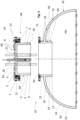
- Fig. 2 shows a sectional view through this top part in the closed state
- Fig. 3 shows the sectional view in the open state
- Fig. 4 shows a perspective view in the closed state
- Fig. 5 shows the perspective view in the open state.
- the multiple wall panel 56 is a double walled access panel.
- This panel 56 has a panel flange 1, an upper wall as the outer panel wall 2 and a lower wall as the inner panel wall 3.
- the closure 48 further includes a multiple wall closure ring 60 with an outer closure ring wall 4, an inner closure ring wall 5 and a closure ring vacuum insulation space 62 between the outer and inner closure ring walls 4, 5.
- the multiple wall closure ring 60 is a kind of "shaft” attached to panel 56.
- This shaft consists of an outer ring as outer closure ring wall 4, an inner ring as inner closure ring wall 5 and a lower closing plate 6. All these parts 1, 2, 3, 4, 5 and 6 are welded together to create a single closure interspace volume 7 - constituted, e.g., by the panel vacuum insulation space 58 and the closure ring vacuum insulating space 62 that are combined in fluid communication at the edge region of the closure 44.
- the air in this volume 7 can be extracted through a vacuum port 8.
- a Multi Layer Insulation (MLI - not shown in detail) 9 is fitted inside the closure interspace volume 7.
- flange - tank flange 11 - mounted at the multiple tank wall 42, that meets the panel flange 1.
- a seal 12 is installed between the tank flange 11 and the panel flange 1.
- the flanges 1, 11 are bolted together by a number of bolt and screw assemblies 13.
- the multiple tank wall 42 includes a multiple wall tank ring 64 with an outer tank ring wall arrangement 14, 15, an inner tank ring wall 16 and a tank ring vacuum insulation space 66 between the outer and inner tank ring walls 14, 15, 16.
- the outer tank ring wall arrangement comprises an inside outer tank ring wall 14 arranged inside of the inner tank wall skin 50 and an outside outer tank ring wall 15 arranged outside of the outer tank wall skin 52.
- the multiple wall tank ring 50 is a kind of "shaft" connected to the tank flange 11.
- This shaft consists of the inside outer tank ring wall 14 (e.g., a lower outer ring made from the tank wall material), the outside outer tank ring wall 15 (e.g., an upper outer ring made from the tank wall material), the inner tank ring wall 16 (e.g., an inner ring made from the tank wall material), and an inside closing plate 17 (e.g., a lower closing plate made from the tank wall material for closing the inside end of the multiple wall tank ring 64).
- the other end of the multiple tank ring wall 64 is tightly closed by the tank flange 11.
- All the tank side parts 11, 14, 15, 16, 17, 50, and 52 are welded to form the multiple tank wall 42 with the access opening 44 defined by the multiple wall tank ring 64.
- a single tank wall interspace volume 18 is created within the multiple tank wall 42.
- the vacuum insulation spaces 54, 66 between the skins 46, 48 and between the tank ring walls 14, 15, 16 are combined into the single tank wall interspace volume 18.
- This tank wall interspace volume 18 is also thermally insulated by a Multi Layer Insulation (MLI - not shown in detail) 19.
- the outer side of the outer closure ring wall 4 and the inner side of the inner tank ring wall 16 have smooth surface which are, in the closed state, in close contact to each other such that a tight fit is created.
- a seal 12 is installed at the panel flange 1 to avoid hydrogen from leaking out of the tank 10.
- Pipes 20 that are running into the cryogenic tank 10 are routed through the access panel 56.
- the pipes 20 are fitted with a double walled section 21 to minimise heat ingress along the pipes 20.
- This double walled section 21 is at one end - here shown at the top - open into the closure interspace volume 7 and creates a common vacuum with the other parts of the panel 56. At the other end - here shown at the bottom - it is closed to the pipe by welding (not shown).
- the interior of the double walled section 21 is insulated by Multi Layer Insulation (MLI - not shown).
- the pipes 20 also serve as a structural support, they ensure the distance between the outer panel wall 2 and the inner panel wall 3.
- the double walled section 21 extends into the interior 46 of the tank, it is also possible that double walled section is arranged outside for thermally insulating a cold inner pipe running into the interior of the tank.
- a cryogenic tank (10) for an aircraft (30) which is providing a tank access for maintenance, inspection and repair inside the tank onboard of the aircraft (30).
- An access opening (44) is closed by a removable closure (48) including a multiple wall panel (56) which is vacuum insulated and which is designed and fitted to the multiple tank wall (42) in a manner that the heat ingress into the cryogenic tank (10) is minimized.
- An advantage is that no vacuum is impacted by opening and closing the removable closure (48).
Landscapes
- Engineering & Computer Science (AREA)
- Mechanical Engineering (AREA)
- General Engineering & Computer Science (AREA)
- Physics & Mathematics (AREA)
- Thermal Sciences (AREA)
- Aviation & Aerospace Engineering (AREA)
- Filling Or Discharging Of Gas Storage Vessels (AREA)
- Pressure Vessels And Lids Thereof (AREA)
Abstract
Description
- The invention relates to a cryogenic tank, especially for an aircraft, comprising a multiple tank wall. Further the invention relates to an aircraft comprising such a LH2 tank.
- According to preferred embodiments, the cryogenic tank is a liquid hydrogen (LH2) tank for storing liquid hydrogen.
- For technical background, reference is made to the following literature:
- [1]
DE 10 2014 107 316 A1 - [2]
US 2021/0 078 702A1 - [3]
WO 2021/148 335A1 - [4]
US 2023/0 002 069 A1 - [5]
EP 4 119 834 A1 - [6]
EP 4 124 568 A1 - [7]
EP 4 124 790 A1 - [8] Product Sheet: Demaco-Cryogenics Johnston Coupling, download on 23.05.2023
- [1] to [3] relate to hydrogen installations in an aircraft. [4] to [7] relate to cryogenic tanks, especially liquid hydrogen tanks (LH2 tanks), for an aircraft and to aircrafts with such a cryogenic tank. [8] relates to a so-called Johnston coupling for coupling cryogenic pipe section.
- Lightweight energy storage is a key topic for next generation aircrafts. Hydrogen offers high energy densities, whereas the storage technique (cryogenic, compressed, solid state/absorbed) is a key issue. Hydrogen can be compressed and/or cooled down to cryogenic temperatures to increase the volumetric and gravimetric energy density. Usually, complex tank systems are needed with individual requirements to the materials, design and working principle e.g., regarding operational safety.
- Compressed and cryogenic hydrogen are the techniques of choice for to-day's vehicles, like cars or airplanes. Cryogenic tanks can achieve the lowest fuel volume / fuel mass ratio. LH2 tanks should have a very good thermal insulation.
- It is the object of the invention to improve hydrogen tanks for use in vehicles, such as aircraft.
- The object is achieved by the subject-matter of the independent claims. Preferred embodiments are subject-matter of the dependent claims.
- The invention provides for a cryogenic tank, especially LH2 tank, comprising a multiple tank wall, an access opening in the multiple tank wall allowing access to an interior of the cryogenic tank for maintenance or repair services and a closure for closing the access opening,
- wherein the multiple tank wall includes an inner tank wall skin, an outer tank wall skin and a tank wall vacuum insulation space between the inner tank wall skin and the outer tank wall skin,
- wherein the closure comprises a multiple wall panel that includes an outer panel wall, an inner panel wall and a panel vacuum insulation space between the outer panel wall and the inner panel wall.
- Preferably, the closure further includes a multiple wall closure ring with an outer closure ring wall, an inner closure ring wall and a closure ring vacuum insulation space between the outer and inner closure ring walls.
- Preferably, a first end of the multiple wall closure ring is tightly closed and a second end of the multiple wall closure ring is tightly connected to the multiple wall panel so that the panel vacuum insulation space and the closure ring vacuum insulation space share a common interspace vacuum volume.
- Preferably, the closure has a vacuum port for evacuation of the common interspace vacuum volume.
- Preferably, a multilayer insulation is fitted inside the common interspace vacuum volume.
- Preferably, the access opening in the multiple tank wall includes a multiple wall tank ring with an outer tank ring wall, an inner tank ring wall and a tank ring vacuum insulation space between the outer and inner tank ring walls.
- Preferably, the ends of the multiple wall tank ring are tightly closed and the outer tank ring wall is tightly connected to the outer and inner tank wall skin so that the tank wall vacuum insulation space and the tank ring vacuum insulation space share a common interspace vacuum volume.
- Preferably, the multiple wall closure ring is insertable in the tank multiple ring wall for closing the access opening.
- Preferably, the inner side of the inner tank ring wall and the outer side of the outer closure ring wall have smooth surfaces configured to create of a tight fit between each other when the access opening is closed by the closure.
- Preferably, the access opening has a tank flange and the closure has a closure flange which mates to the tank flange so that in a closed state the closure flange is tightly connected, especially by a number of bolt and screw assemblies, to the tank flange.
- Preferably, at least one pipe runs through the closure and has a multiple wall pipe section fixed to the closure.
- Preferably, the multiple wall section has an inner pipe wall and an outer pipe wall with a pipe vacuum insulation space therebetween.
- Preferably, the pipe vacuum insulation space and the panel vacuum insulation space share a common interspace vacuum volume.
- Preferably, the multiwall pipe section extends from the inner panel wall and the outer pipe wall is connected to the inner panel wall.
- Alternatively, the multiwall pipe section extends from the outer panel wall and the outer pipe wall is connected to the outer panel wall.
- Preferably, several of the pipes run through the closure and are fixed to the inner and outer panel walls as a structural support and/or in order to maintain the distance between the inner and outer panel walls.
- According to another aspect, the invention provides an aircraft comprising a cryogenic tank according to any of the preceding embodiments.
- Preferred embodiments of the invention relate to a vacuum insulated access panel for a cryogenic tank such as a liquid hydrogen tank (LH2 tank).
- Preferred embodiments of the invention improve the design of a liquid hydrogen tank. Preferably, the tank is of the double wall vacuum insulated design, which is the state of art tank design for such applications. Embodiments of the invention allow to open the tank and get access to the inner part without breaking the tank vacuum. Preferred uses of such design are on hydrogen powered aircraft.
- Currently, hydrogen tanks are completely closed, normally by welding. It is impossible to get access to the inner part of the tank without cutting the welds or the tank structure. Hence, equipment or installations inside the tank can only be maintained or replaced with a large effort. As a consequence, normally the complete tank needs to be removed from the aircraft and repaired in a shop outside the aircraft.
- Some conventional aircraft fuel tanks have access openings allowing access to the interior of the fuel tank on board of the aircraft for repair and maintenance purposes. With embodiments of the invention, such a tank access for maintenance and repair can now also be provided for liquid hydrogen tanks or other cryogenic tank to be used on aircrafts. In embodiments of the invention, the tank access opening is closed by a closure including a panel. In some embodiments, this panel is double walled and vacuum insulated. The panel is designed and fitted to the tank in manner that the heat ingress into the cold hydrogen is minimised.
- Embodiments of the invention are explained below referring to the accompanying drawings in which:
- Fig. 1
- depicts an aircraft having a cryogenic tank;
- Fig. 2
- is a sectional view through a part of the cryogenic tank (e.g., a top part) with an access opening and a closure for this access opening in a closed state;
- Fig. 3
- is a sectional view as in Fig. 2 wherein the access opening and the closure are in an open state;
- Fig. 4
- is a perspective view of the part of the cryogenic tank with the access opening and the closure in the closed state; and
- Fig. 5
- is a perspective view of the part of the cryogenic tank with the access opening and the closure in the open state.
- Referring to
Fig. 1 , anaircraft 30 comprises afuselage 32. Theaircraft 30 further comprises a pair ofwings 34 that are attached to thefuselage 32. Furthermore, anengine 36 is attached to eachwing 34. - The
aircraft 30 comprises anaft section 38, which includes a horizontal and vertical tail plane. Furthermore, theaircraft 30 comprises atank arrangement 40. Thetank arrangement 40 includes acryogenic tank 10 that is preferably arranged in theaft section 38. It should be noted that thecryogenic tank 10 may have a different shape and/or be located in a different section of theaircraft 30. - The
tank 10 includes hydrogen fuel that can be directly fed to theengines 36. The hydrogen fuel may also be fed to fuel cells (not depicted) where the hydrogen is converted into electrical energy, and the electrical energy is then fed to theengines 36. The hydrogen fuel is stored in thetank 10 in the form of a cryogenic liquid, i.e., liquid hydrogen (LH2). - Referring to Figs. 2 to 5, an embodiment of the
cryogenic tank 10 is explained in more detail. - The
cryogenic tank 10 comprises amultiple tank wall 42, an access opening 44 in themultiple tank wall 42 allowing access to an interior 46 of thecryogenic tank 10 for maintenance or repair services and aclosure 48 for closing theaccess opening 44. - In the embodiment shown, the
cryogenic tank 10 is a doublewalled tank 10 wherein themultiple tank wall 42 includes an innertank wall skin 50, an outertank wall skin 52 and a tank wallvacuum insulation space 54 between the innertank wall skin 50 and the outertank wall skin 52. - The
closure 48 comprises amultiple wall panel 56 that includes anouter panel wall 2, aninner panel wall 3 and a panelvacuum insulation space 58 between theouter panel wall 2 and theinner panel wall 3. - In the embodiments shown, the access opening 44 is arranged in a top part of the
cryogenic tank 10. Fig. 2 shows a sectional view through this top part in the closed state, Fig. 3 shows the sectional view in the open state; Fig. 4 shows a perspective view in the closed state and Fig. 5 shows the perspective view in the open state. - In the embodiments shown, the
multiple wall panel 56 is a double walled access panel. Thispanel 56 has apanel flange 1, an upper wall as theouter panel wall 2 and a lower wall as theinner panel wall 3. - In some embodiments, the
closure 48 further includes a multiplewall closure ring 60 with an outerclosure ring wall 4, an innerclosure ring wall 5 and a closure ringvacuum insulation space 62 between the outer and innerclosure ring walls wall closure ring 60 is a kind of "shaft" attached topanel 56. This shaft consists of an outer ring as outerclosure ring wall 4, an inner ring as innerclosure ring wall 5 and alower closing plate 6. All theseparts vacuum insulation space 58 and the closure ringvacuum insulating space 62 that are combined in fluid communication at the edge region of theclosure 44. The air in thisvolume 7 can be extracted through avacuum port 8. A Multi Layer Insulation (MLI - not shown in detail) 9 is fitted inside theclosure interspace volume 7. - On the side of the
multiple tank wall 42 there is another flange - tank flange 11 - mounted at themultiple tank wall 42, that meets thepanel flange 1. Aseal 12 is installed between thetank flange 11 and thepanel flange 1. Theflanges screw assemblies 13. - In some embodiments, the
multiple tank wall 42 includes a multiplewall tank ring 64 with an outer tankring wall arrangement tank ring wall 16 and a tank ringvacuum insulation space 66 between the outer and innertank ring walls tank ring wall 14 arranged inside of the innertank wall skin 50 and an outside outertank ring wall 15 arranged outside of the outertank wall skin 52. In the embodiments shown, the multiplewall tank ring 50 is a kind of "shaft" connected to thetank flange 11. This shaft consists of the inside outer tank ring wall 14 (e.g., a lower outer ring made from the tank wall material), the outside outer tank ring wall 15 (e.g., an upper outer ring made from the tank wall material), the inner tank ring wall 16 (e.g., an inner ring made from the tank wall material), and an inside closing plate 17 (e.g., a lower closing plate made from the tank wall material for closing the inside end of the multiple wall tank ring 64). The other end of the multipletank ring wall 64 is tightly closed by thetank flange 11. - All the
tank side parts multiple tank wall 42 with the access opening 44 defined by the multiplewall tank ring 64. A single tankwall interspace volume 18 is created within themultiple tank wall 42. In other words, thevacuum insulation spaces skins tank ring walls wall interspace volume 18. This tankwall interspace volume 18 is also thermally insulated by a Multi Layer Insulation (MLI - not shown in detail) 19. - The outer side of the outer
closure ring wall 4 and the inner side of the innertank ring wall 16 have smooth surface which are, in the closed state, in close contact to each other such that a tight fit is created. Aseal 12 is installed at thepanel flange 1 to avoid hydrogen from leaking out of thetank 10. -
Pipes 20 that are running into thecryogenic tank 10 are routed through theaccess panel 56. Thepipes 20 are fitted with a doublewalled section 21 to minimise heat ingress along thepipes 20. This doublewalled section 21 is at one end - here shown at the top - open into theclosure interspace volume 7 and creates a common vacuum with the other parts of thepanel 56. At the other end - here shown at the bottom - it is closed to the pipe by welding (not shown). The interior of the doublewalled section 21 is insulated by Multi Layer Insulation (MLI - not shown). - The
pipes 20 also serve as a structural support, they ensure the distance between theouter panel wall 2 and theinner panel wall 3. - In the embodiments shown, the double
walled section 21 extends into the interior 46 of the tank, it is also possible that double walled section is arranged outside for thermally insulating a cold inner pipe running into the interior of the tank. - A cryogenic tank (10) for an aircraft (30) has been described which is providing a tank access for maintenance, inspection and repair inside the tank onboard of the aircraft (30). An access opening (44) is closed by a removable closure (48) including a multiple wall panel (56) which is vacuum insulated and which is designed and fitted to the multiple tank wall (42) in a manner that the heat ingress into the cryogenic tank (10) is minimized. An advantage is that no vacuum is impacted by opening and closing the removable closure (48).
-
- 1
- panel flange
- 2
- outer panel wall
- 3
- inner panel wall
- 4
- outer closure ring wall
- 5
- inner closure ring wall
- 6
- closure plate
- 7
- closure interspace volume
- 8
- vacuum port
- 9
- Multi Layer Insulation (in closure interspace volume)
- 10
- cryogenic tank
- 11
- tank flange
- 12
- seal
- 13
- bolt and screw arrangement
- 14
- inside outer tank ring wall
- 15
- outside outer tank ring wall
- 16
- inner tank ring wall
- 17
- end plate (of the multiple wall tank ring)
- 18
- tank wall interspace volume
- 19
- Multi Layer Insulation (in the tank wall interspace volume)
- 20
- pipe
- 21
- double wall section
- 30
- aircraft
- 32
- fuselage
- 34
- wing
- 36
- engine
- 38
- aft section
- 40
- tank arrangement
- 42
- multiple tank wall (e.g., double tank wall)
- 44
- access opening
- 46
- interior of the tank
- 48
- closure
- 50
- inner tank wall skin
- 52
- outer tank wall skin
- 54
- tank wall insulation space
- 56
- panel
- 58
- panel vacuum insulation space
- 60
- multiple wall closure ring
- 62
- closure ring vacuum insulation space
- 64
- multiple wall tank ring
- 66
- tank ring vacuum insulation space
Claims (12)
- Cryogenic tank (10) comprising a multiple tank wall (42), an access opening (44) in the multiple tank wall (42) allowing access to an interior (46) of the cryogenic tank (10) for maintenance, repair and/or replacement services and a removable closure (48) for closing the access opening (44),wherein the multiple tank wall (42) includes an inner tank wall skin (50), an outer tank wall skin (52) and a tank wall vacuum insulation space (54) between the inner tank wall skin (50) and the outer tank wall skin (52),wherein the closure (48) comprises a multiple wall panel (56) that includes an outer panel wall (2), an inner panel wall (3) and a panel vacuum insulation space (58) between the outer panel wall (2) and the inner panel wall (3).
- Cryogenic tank (10) according to claim 1, characterized in that the closure (48) further includes a multiple wall closure ring (60) with an outer closure ring wall (4), an inner closure ring wall (5) and a closure ring vacuum insulation space (62) between the outer and inner closure ring walls (4, 5).
- Cryogenic tank (10) according to claim 2, characterized in that a first end of the multiple wall closure ring (60) is tightly closed and a second end of the multiple wall closure ring (60) is tightly connected to the multiple wall panel (56) so that the panel vacuum insulation space (58) and the closure ring vacuum insulation space (62) form a single closure interspace vacuum volume (7).
- Cryogenic tank (10) according to claim 3, characterized in that4.1 the closure (48) has a vacuum port (8) for evacuation of the closure interspace vacuum volume (7); and/or4.2 a multilayer insulation (9) is fitted inside the closure interspace vacuum volume (7).
- Cryogenic tank (10) according to any of the preceding claims, characterized in that the access opening (44) in the multiple tank wall (42) is defined by a multiple wall tank ring (64) with an outer tank ring wall arrangement (14, 15), an inner tank ring wall (16) and a tank ring vacuum insulation space (66) between the outer and inner tank ring walls (14, 15, 16).
- Cryogenic tank (10) according to claim 6, characterized in that6.1 the ends of the multiple wall tank ring (64) are tightly closed, and/or6.2 the outer tank ring wall arrangement comprises an inside outer tank ring wall (14) arranged inside the inner tank wall skin (50) and an outside outer tank ring wall (15) arranged outside the outer tank wall skin (52); and/or6.3 the outer tank ring wall arrangement (14, 15) is tightly connected to the outer and inner tank wall skin (50, 52) so that the tank wall vacuum insulation space (54) and the tank ring vacuum insulation space (66) are in fluid communication with each other and/or form a single tank wall interspace vacuum volume (18).
- Cryogenic tank (10) according to any of the claims 5 or 6 and any of the claims 2 to 4, characterized in that7.1 the multiple wall closure ring (64) is insertable in the multiple wall tank ring (64) for closing the access opening (44); and/or7.2 the inner side of the inner tank ring wall (16) and the outer side of the outer closure ring wall (4) have smooth surfaces configured to create of a tight fit between each other when the access opening (44) is closed by the closure (48).
- Cryogenic tank (10) according to any of the preceding claims, characterized in that the access opening (44) has a tank flange (11) and the closure (48) has a closure flange (1) which mates to the tank flange (11) so that in a closed state the closure flange (1) is tightly connected, especially by a number of bolt and screw assemblies (13), to the tank flange (11).
- Cryogenic tank (10) according to any of the preceding claims characterized in that at least one pipe (20) runs through the closure (48) and has a multiple wall pipe section (21) fixed to the closure (48).
- Cryogenic tank (10) according to claim 9 characterized in that the multiple wall section (21) has an inner pipe wall and an outer pipe wall with a pipe vacuum insulation space therebetween, especially such that10.1 the pipe vacuum insulation space is in fluid communication with the panel vacuum insulation space, and/or10.2 the multiwall pipe section (21) extends from the inner panel wall (3) and the outer pipe wall is connected to the inner panel wall (3) or10.3 the multiwall pipe section (21) extends from the outer panel wall (2) and the outer pipe wall is connected to the outer panel wall (2).
- Cryogenic tank (10) according to claim 9 or 10 characterized in that that several of the pipes (20) run through the closure (48) and are fixed to the inner and outer panel walls (2, 3) as a structural support and/or in order to maintain the distance between the inner and outer panel walls (2, 3).
- Aircraft (20) comprising a cryogenic tank (10) according to any of the preceding claims.
Priority Applications (4)
| Application Number | Priority Date | Filing Date | Title |
|---|---|---|---|
| EP23176491.1A EP4471322A1 (en) | 2023-05-31 | 2023-05-31 | Cryogenic tank with access opening, and aircraft equipped therewith |
| US18/670,775 US20240401749A1 (en) | 2023-05-31 | 2024-05-22 | Cryogenic tank with access opening, and aircraft equipped therewith |
| JP2024085567A JP2024173766A (en) | 2023-05-31 | 2024-05-27 | Cryogenic tank with access opening and aircraft equipped with same |
| CN202410678732.XA CN119058962A (en) | 2023-05-31 | 2024-05-29 | Cryogenic tank and aircraft including the same |
Applications Claiming Priority (1)
| Application Number | Priority Date | Filing Date | Title |
|---|---|---|---|
| EP23176491.1A EP4471322A1 (en) | 2023-05-31 | 2023-05-31 | Cryogenic tank with access opening, and aircraft equipped therewith |
Publications (1)
| Publication Number | Publication Date |
|---|---|
| EP4471322A1 true EP4471322A1 (en) | 2024-12-04 |
Family
ID=86646636
Family Applications (1)
| Application Number | Title | Priority Date | Filing Date |
|---|---|---|---|
| EP23176491.1A Pending EP4471322A1 (en) | 2023-05-31 | 2023-05-31 | Cryogenic tank with access opening, and aircraft equipped therewith |
Country Status (4)
| Country | Link |
|---|---|
| US (1) | US20240401749A1 (en) |
| EP (1) | EP4471322A1 (en) |
| JP (1) | JP2024173766A (en) |
| CN (1) | CN119058962A (en) |
Citations (3)
| Publication number | Priority date | Publication date | Assignee | Title |
|---|---|---|---|---|
| EP2937297A1 (en) * | 2012-12-19 | 2015-10-28 | Kawasaki Jukogyo Kabushiki Kaisha | Transport container for liquefied gas |
| WO2017042424A1 (en) * | 2015-09-11 | 2017-03-16 | Wärtsilä Finland Oy | A fuel tank arrangement of a marine vessel |
| FR3106190A1 (en) * | 2020-01-13 | 2021-07-16 | Gaztransport Et Technigaz | Double access hatch for a liquefied gas transport tank |
Family Cites Families (2)
| Publication number | Priority date | Publication date | Assignee | Title |
|---|---|---|---|---|
| JP6855219B2 (en) * | 2016-11-18 | 2021-04-07 | 川崎重工業株式会社 | Insulated container for cryogenic gas pump |
| US12017789B2 (en) * | 2021-10-05 | 2024-06-25 | General Electric Company | Onboard liquid hydrogen storage for a hydrogen aircraft |
-
2023
- 2023-05-31 EP EP23176491.1A patent/EP4471322A1/en active Pending
-
2024
- 2024-05-22 US US18/670,775 patent/US20240401749A1/en active Pending
- 2024-05-27 JP JP2024085567A patent/JP2024173766A/en active Pending
- 2024-05-29 CN CN202410678732.XA patent/CN119058962A/en active Pending
Patent Citations (3)
| Publication number | Priority date | Publication date | Assignee | Title |
|---|---|---|---|---|
| EP2937297A1 (en) * | 2012-12-19 | 2015-10-28 | Kawasaki Jukogyo Kabushiki Kaisha | Transport container for liquefied gas |
| WO2017042424A1 (en) * | 2015-09-11 | 2017-03-16 | Wärtsilä Finland Oy | A fuel tank arrangement of a marine vessel |
| FR3106190A1 (en) * | 2020-01-13 | 2021-07-16 | Gaztransport Et Technigaz | Double access hatch for a liquefied gas transport tank |
Also Published As
| Publication number | Publication date |
|---|---|
| US20240401749A1 (en) | 2024-12-05 |
| CN119058962A (en) | 2024-12-03 |
| JP2024173766A (en) | 2024-12-12 |
Similar Documents
| Publication | Publication Date | Title |
|---|---|---|
| CN108224071B (en) | Additively manufactured reinforcement structures | |
| EP2848520B1 (en) | Cryogenic fuel tanks for use in aircraft structures | |
| US9168716B2 (en) | Metallic sandwich structure having small bend radius | |
| US12337989B2 (en) | Cryogenic tank | |
| JP6145476B2 (en) | Aircraft comprising a framework structure having at least one hollow frame | |
| US20100038472A1 (en) | Airplane with rear engines | |
| US20160229513A1 (en) | Aircraft tail cone | |
| EP3932801B1 (en) | A rotary wing aircraft with a firewall arrangement | |
| CN103402873A (en) | Heat exchanger built into a wall of an aircraft | |
| US12240622B2 (en) | Aircraft assembly | |
| US12264782B2 (en) | Hydrogen cryogenic non circular dorsal tank | |
| EP4455017B1 (en) | Fuel tank for aircraft, processor of aircraft, and aircraft | |
| US20250368346A1 (en) | Battery Storage System for an Aircraft | |
| US7980513B2 (en) | Water-wastewater module for aircraft | |
| US12559251B2 (en) | Method and apparatus for auxiliary power unit installation | |
| US20220332411A1 (en) | Rotary wing aircraft with a firewall arrangement | |
| US20240401749A1 (en) | Cryogenic tank with access opening, and aircraft equipped therewith | |
| EP4653754A1 (en) | Removable closure for a cryogenic tank, especially for an aircraft, cryogenic tank, and aircraft | |
| US12241577B2 (en) | Fluid pipe connection | |
| EP2562087B1 (en) | Inert gas distribution system for a fuel tank | |
| DE102005045130B4 (en) | Water sewer module for aircraft | |
| EP4718611A1 (en) | Aircraft with battery venting manifold assembly | |
| CN216035082U (en) | Whole oil tank of high aspect ratio combined material structure | |
| CN121626438A (en) | An embedded irregular-shaped pressure auxiliary oil tank | |
| GB2631725A (en) | A battery pack |
Legal Events
| Date | Code | Title | Description |
|---|---|---|---|
| PUAI | Public reference made under article 153(3) epc to a published international application that has entered the european phase |
Free format text: ORIGINAL CODE: 0009012 |
|
| STAA | Information on the status of an ep patent application or granted ep patent |
Free format text: STATUS: THE APPLICATION HAS BEEN PUBLISHED |
|
| AK | Designated contracting states |
Kind code of ref document: A1 Designated state(s): AL AT BE BG CH CY CZ DE DK EE ES FI FR GB GR HR HU IE IS IT LI LT LU LV MC ME MK MT NL NO PL PT RO RS SE SI SK SM TR |
|
| STAA | Information on the status of an ep patent application or granted ep patent |
Free format text: STATUS: REQUEST FOR EXAMINATION WAS MADE |
|
| 17P | Request for examination filed |
Effective date: 20250522 |
|
| GRAP | Despatch of communication of intention to grant a patent |
Free format text: ORIGINAL CODE: EPIDOSNIGR1 |
|
| STAA | Information on the status of an ep patent application or granted ep patent |
Free format text: STATUS: GRANT OF PATENT IS INTENDED |
|
| INTG | Intention to grant announced |
Effective date: 20260323 |
|
| GRAS | Grant fee paid |
Free format text: ORIGINAL CODE: EPIDOSNIGR3 |