EP4471317A1 - Method to control the filling of movable gas storages - Google Patents
Method to control the filling of movable gas storages Download PDFInfo
- Publication number
- EP4471317A1 EP4471317A1 EP23176083.6A EP23176083A EP4471317A1 EP 4471317 A1 EP4471317 A1 EP 4471317A1 EP 23176083 A EP23176083 A EP 23176083A EP 4471317 A1 EP4471317 A1 EP 4471317A1
- Authority
- EP
- European Patent Office
- Prior art keywords
- filling
- storage
- gas
- dispenser
- queue
- Prior art date
- Legal status (The legal status is an assumption and is not a legal conclusion. Google has not performed a legal analysis and makes no representation as to the accuracy of the status listed.)
- Withdrawn
Links
Images


Classifications
-
- F—MECHANICAL ENGINEERING; LIGHTING; HEATING; WEAPONS; BLASTING
- F17—STORING OR DISTRIBUTING GASES OR LIQUIDS
- F17C—VESSELS FOR CONTAINING OR STORING COMPRESSED, LIQUEFIED OR SOLIDIFIED GASES; FIXED-CAPACITY GAS-HOLDERS; FILLING VESSELS WITH, OR DISCHARGING FROM VESSELS, COMPRESSED, LIQUEFIED, OR SOLIDIFIED GASES
- F17C5/00—Methods or apparatus for filling containers with liquefied, solidified, or compressed gases under pressures
- F17C5/002—Automated filling apparatus
- F17C5/007—Automated filling apparatus for individual gas tanks or containers, e.g. in vehicles
-
- F—MECHANICAL ENGINEERING; LIGHTING; HEATING; WEAPONS; BLASTING
- F17—STORING OR DISTRIBUTING GASES OR LIQUIDS
- F17C—VESSELS FOR CONTAINING OR STORING COMPRESSED, LIQUEFIED OR SOLIDIFIED GASES; FIXED-CAPACITY GAS-HOLDERS; FILLING VESSELS WITH, OR DISCHARGING FROM VESSELS, COMPRESSED, LIQUEFIED, OR SOLIDIFIED GASES
- F17C5/00—Methods or apparatus for filling containers with liquefied, solidified, or compressed gases under pressures
- F17C5/06—Methods or apparatus for filling containers with liquefied, solidified, or compressed gases under pressures for filling with compressed gases
-
- F—MECHANICAL ENGINEERING; LIGHTING; HEATING; WEAPONS; BLASTING
- F17—STORING OR DISTRIBUTING GASES OR LIQUIDS
- F17C—VESSELS FOR CONTAINING OR STORING COMPRESSED, LIQUEFIED OR SOLIDIFIED GASES; FIXED-CAPACITY GAS-HOLDERS; FILLING VESSELS WITH, OR DISCHARGING FROM VESSELS, COMPRESSED, LIQUEFIED, OR SOLIDIFIED GASES
- F17C2201/00—Vessel construction, in particular geometry, arrangement or size
- F17C2201/01—Shape
- F17C2201/0104—Shape cylindrical
- F17C2201/0109—Shape cylindrical with exteriorly curved end-piece
-
- F—MECHANICAL ENGINEERING; LIGHTING; HEATING; WEAPONS; BLASTING
- F17—STORING OR DISTRIBUTING GASES OR LIQUIDS
- F17C—VESSELS FOR CONTAINING OR STORING COMPRESSED, LIQUEFIED OR SOLIDIFIED GASES; FIXED-CAPACITY GAS-HOLDERS; FILLING VESSELS WITH, OR DISCHARGING FROM VESSELS, COMPRESSED, LIQUEFIED, OR SOLIDIFIED GASES
- F17C2201/00—Vessel construction, in particular geometry, arrangement or size
- F17C2201/03—Orientation
- F17C2201/035—Orientation with substantially horizontal main axis
-
- F—MECHANICAL ENGINEERING; LIGHTING; HEATING; WEAPONS; BLASTING
- F17—STORING OR DISTRIBUTING GASES OR LIQUIDS
- F17C—VESSELS FOR CONTAINING OR STORING COMPRESSED, LIQUEFIED OR SOLIDIFIED GASES; FIXED-CAPACITY GAS-HOLDERS; FILLING VESSELS WITH, OR DISCHARGING FROM VESSELS, COMPRESSED, LIQUEFIED, OR SOLIDIFIED GASES
- F17C2201/00—Vessel construction, in particular geometry, arrangement or size
- F17C2201/05—Size
- F17C2201/054—Size medium (>1 m3)
-
- F—MECHANICAL ENGINEERING; LIGHTING; HEATING; WEAPONS; BLASTING
- F17—STORING OR DISTRIBUTING GASES OR LIQUIDS
- F17C—VESSELS FOR CONTAINING OR STORING COMPRESSED, LIQUEFIED OR SOLIDIFIED GASES; FIXED-CAPACITY GAS-HOLDERS; FILLING VESSELS WITH, OR DISCHARGING FROM VESSELS, COMPRESSED, LIQUEFIED, OR SOLIDIFIED GASES
- F17C2221/00—Handled fluid, in particular type of fluid
- F17C2221/01—Pure fluids
- F17C2221/012—Hydrogen
-
- F—MECHANICAL ENGINEERING; LIGHTING; HEATING; WEAPONS; BLASTING
- F17—STORING OR DISTRIBUTING GASES OR LIQUIDS
- F17C—VESSELS FOR CONTAINING OR STORING COMPRESSED, LIQUEFIED OR SOLIDIFIED GASES; FIXED-CAPACITY GAS-HOLDERS; FILLING VESSELS WITH, OR DISCHARGING FROM VESSELS, COMPRESSED, LIQUEFIED, OR SOLIDIFIED GASES
- F17C2223/00—Handled fluid before transfer, i.e. state of fluid when stored in the vessel or before transfer from the vessel
- F17C2223/01—Handled fluid before transfer, i.e. state of fluid when stored in the vessel or before transfer from the vessel characterised by the phase
- F17C2223/0107—Single phase
- F17C2223/0123—Single phase gaseous, e.g. CNG, GNC
-
- F—MECHANICAL ENGINEERING; LIGHTING; HEATING; WEAPONS; BLASTING
- F17—STORING OR DISTRIBUTING GASES OR LIQUIDS
- F17C—VESSELS FOR CONTAINING OR STORING COMPRESSED, LIQUEFIED OR SOLIDIFIED GASES; FIXED-CAPACITY GAS-HOLDERS; FILLING VESSELS WITH, OR DISCHARGING FROM VESSELS, COMPRESSED, LIQUEFIED, OR SOLIDIFIED GASES
- F17C2227/00—Transfer of fluids, i.e. method or means for transferring the fluid; Heat exchange with the fluid
- F17C2227/01—Propulsion of the fluid
- F17C2227/0128—Propulsion of the fluid with pumps or compressors
- F17C2227/0157—Compressors
-
- F—MECHANICAL ENGINEERING; LIGHTING; HEATING; WEAPONS; BLASTING
- F17—STORING OR DISTRIBUTING GASES OR LIQUIDS
- F17C—VESSELS FOR CONTAINING OR STORING COMPRESSED, LIQUEFIED OR SOLIDIFIED GASES; FIXED-CAPACITY GAS-HOLDERS; FILLING VESSELS WITH, OR DISCHARGING FROM VESSELS, COMPRESSED, LIQUEFIED, OR SOLIDIFIED GASES
- F17C2227/00—Transfer of fluids, i.e. method or means for transferring the fluid; Heat exchange with the fluid
- F17C2227/04—Methods for emptying or filling
- F17C2227/041—Methods for emptying or filling vessel by vessel
-
- F—MECHANICAL ENGINEERING; LIGHTING; HEATING; WEAPONS; BLASTING
- F17—STORING OR DISTRIBUTING GASES OR LIQUIDS
- F17C—VESSELS FOR CONTAINING OR STORING COMPRESSED, LIQUEFIED OR SOLIDIFIED GASES; FIXED-CAPACITY GAS-HOLDERS; FILLING VESSELS WITH, OR DISCHARGING FROM VESSELS, COMPRESSED, LIQUEFIED, OR SOLIDIFIED GASES
- F17C2250/00—Accessories; Control means; Indicating, measuring or monitoring of parameters
- F17C2250/03—Control means
- F17C2250/032—Control means using computers
-
- F—MECHANICAL ENGINEERING; LIGHTING; HEATING; WEAPONS; BLASTING
- F17—STORING OR DISTRIBUTING GASES OR LIQUIDS
- F17C—VESSELS FOR CONTAINING OR STORING COMPRESSED, LIQUEFIED OR SOLIDIFIED GASES; FIXED-CAPACITY GAS-HOLDERS; FILLING VESSELS WITH, OR DISCHARGING FROM VESSELS, COMPRESSED, LIQUEFIED, OR SOLIDIFIED GASES
- F17C2250/00—Accessories; Control means; Indicating, measuring or monitoring of parameters
- F17C2250/04—Indicating or measuring of parameters as input values
- F17C2250/0404—Parameters indicated or measured
- F17C2250/043—Pressure
-
- F—MECHANICAL ENGINEERING; LIGHTING; HEATING; WEAPONS; BLASTING
- F17—STORING OR DISTRIBUTING GASES OR LIQUIDS
- F17C—VESSELS FOR CONTAINING OR STORING COMPRESSED, LIQUEFIED OR SOLIDIFIED GASES; FIXED-CAPACITY GAS-HOLDERS; FILLING VESSELS WITH, OR DISCHARGING FROM VESSELS, COMPRESSED, LIQUEFIED, OR SOLIDIFIED GASES
- F17C2250/00—Accessories; Control means; Indicating, measuring or monitoring of parameters
- F17C2250/04—Indicating or measuring of parameters as input values
- F17C2250/0404—Parameters indicated or measured
- F17C2250/0473—Time or time periods
-
- F—MECHANICAL ENGINEERING; LIGHTING; HEATING; WEAPONS; BLASTING
- F17—STORING OR DISTRIBUTING GASES OR LIQUIDS
- F17C—VESSELS FOR CONTAINING OR STORING COMPRESSED, LIQUEFIED OR SOLIDIFIED GASES; FIXED-CAPACITY GAS-HOLDERS; FILLING VESSELS WITH, OR DISCHARGING FROM VESSELS, COMPRESSED, LIQUEFIED, OR SOLIDIFIED GASES
- F17C2250/00—Accessories; Control means; Indicating, measuring or monitoring of parameters
- F17C2250/06—Controlling or regulating of parameters as output values
- F17C2250/0605—Parameters
- F17C2250/0636—Flow or movement of content
-
- F—MECHANICAL ENGINEERING; LIGHTING; HEATING; WEAPONS; BLASTING
- F17—STORING OR DISTRIBUTING GASES OR LIQUIDS
- F17C—VESSELS FOR CONTAINING OR STORING COMPRESSED, LIQUEFIED OR SOLIDIFIED GASES; FIXED-CAPACITY GAS-HOLDERS; FILLING VESSELS WITH, OR DISCHARGING FROM VESSELS, COMPRESSED, LIQUEFIED, OR SOLIDIFIED GASES
- F17C2260/00—Purposes of gas storage and gas handling
- F17C2260/02—Improving properties related to fluid or fluid transfer
-
- F—MECHANICAL ENGINEERING; LIGHTING; HEATING; WEAPONS; BLASTING
- F17—STORING OR DISTRIBUTING GASES OR LIQUIDS
- F17C—VESSELS FOR CONTAINING OR STORING COMPRESSED, LIQUEFIED OR SOLIDIFIED GASES; FIXED-CAPACITY GAS-HOLDERS; FILLING VESSELS WITH, OR DISCHARGING FROM VESSELS, COMPRESSED, LIQUEFIED, OR SOLIDIFIED GASES
- F17C2260/00—Purposes of gas storage and gas handling
- F17C2260/03—Dealing with losses
- F17C2260/035—Dealing with losses of fluid
- F17C2260/038—Detecting leaked fluid
-
- F—MECHANICAL ENGINEERING; LIGHTING; HEATING; WEAPONS; BLASTING
- F17—STORING OR DISTRIBUTING GASES OR LIQUIDS
- F17C—VESSELS FOR CONTAINING OR STORING COMPRESSED, LIQUEFIED OR SOLIDIFIED GASES; FIXED-CAPACITY GAS-HOLDERS; FILLING VESSELS WITH, OR DISCHARGING FROM VESSELS, COMPRESSED, LIQUEFIED, OR SOLIDIFIED GASES
- F17C2265/00—Effects achieved by gas storage or gas handling
- F17C2265/06—Fluid distribution
- F17C2265/061—Fluid distribution for supply of supplying vehicles
-
- F—MECHANICAL ENGINEERING; LIGHTING; HEATING; WEAPONS; BLASTING
- F17—STORING OR DISTRIBUTING GASES OR LIQUIDS
- F17C—VESSELS FOR CONTAINING OR STORING COMPRESSED, LIQUEFIED OR SOLIDIFIED GASES; FIXED-CAPACITY GAS-HOLDERS; FILLING VESSELS WITH, OR DISCHARGING FROM VESSELS, COMPRESSED, LIQUEFIED, OR SOLIDIFIED GASES
- F17C2270/00—Applications
- F17C2270/01—Applications for fluid transport or storage
- F17C2270/0134—Applications for fluid transport or storage placed above the ground
- F17C2270/0139—Fuel stations
Definitions
- the (present) invention relates to a method to control the filling of gas to movable storages, where the gas is produced by an electrolyzer powered by a renewable energy source, such as by wind turbines.
- tube trailers are an attractive alternative. They break the chicken-and-egg dilemma by allowing for the transport of gas between any two road connected locations of production and consumption.
- the gas from an electrolyzer is compressed for road transport up to several hundreds of bars. This is done using a compressor with a refueling dispenser which serves as an interface between the site and the mobile off-taker.
- the filling process of a high-capacity tube trailer is an operation that typically takes several hours due to gas flow limitations. Additionally, the availability and production rate of the electrolyzer may be less than 100% due to the intermittent power availability from the wind turbine.
- This trailer exchange should occur independently while a third tube trailer is undergoing the filling process where gas is delivered by the compressor.
- a driver arriving at a site with an empty tube trailer has a choice: Either manually abort the existing tube trailer filling (e.g. at 90% fill level) or wait for the tube trailer filling process to end. If the driver is too late then the gas production would eventually stop as no offtake is available.
- Tube trailers off-taker typically requires more flexibility, especially to transport tube trailers to and from a remote PtX site.
- the tube trailer fleet size poses an additional restriction to tube trailer availability, as well as number of drivers available.
- driver would prefer to arrive in the day times and connect the tube trailers to the dispensers at the offtake section.
- a tube trailer is first flushed, and leak tested until it is ready for filling. Only the filling step requires compressor action.
- Each tube trailer is connected to a dedicated dispenser. However, drivers need to wait before manually to start the filling process.
- the compressor may stop during filling for many reasons, e.g. if gas production is paused and no gas buffer is available.
- the waiting dispensers could then potentially engage in filling as the compressor stop could be interpreted as filling complete. This would result in an opening of valves at several dispensers with the risk of violent gas transfer during pressure balancing of the tube trailer gas vessels. Additionally, gas transfer to the filling trailer would stop as gas always flows into the trailer at the lowest pressure.
- an offtake section consisted of 6 dispensers, then this could be accomplished by two subsections of three dispensers and each sub-section with its dedicated compressor, i.e. two compressors in total.
- the invention aims to solve the above problems, such as where one or multiple tube trailer arrive at a PtX site, how they are to be prepared for filling and how this is managed by a central control system.
- a method to control the filling of a gas storage with gas produced by a gas production plant comprising a plural of selectable gas dispensers and an electrolyzer powered by a renewable energy source, the method including, if there is an available dispenser, connect a gas storage with available storage capacity to the available dispenser and start a filling sequence, the filling sequence including a step of
- Each filling request prioritized and stored in the queue thus is associated with a specific gas storage.
- the gas reservoir could be connected the available dispenser before sending the filling request. This could be enabled by the available dispenser known to be closed, thus allowing safe connection.
- the filling request is sent before the connection. This could e.g., be the operator being informed the dispenser now is available for connection, or the connection is only made possible once a signal is given the dispenser is ready for connection.
- the method may include, when the filling of a gas storage is active, registering when it is full, then initiating the steps of deactivating the respective dispenser and send the signal to activate the next dispenser. Again, by the next dispenser is referred to the dispenser connected to the gas storage with the highest priority filling request in the queue.
- the step of prioritizing may include an estimate of the time to fill the storage, this could include for a higher priority to be given to a storage with a low comparable capacity compared to other storages in the queue.
- the method to estimate the time to fill the storage is based on registering the inner pressure of the storage.
- the step of prioritizing may include the time of arrival compared to other storages in the queue.
- the step of prioritizing may include a weighted combination of the time to fill the storage and the time of arrival.
- the dispensers may be connected to a shared flow generating device for feeding gas to the dispensers.
- the flow generating device may be a compressor.
- the safety check may include flush and leak tests.
- the filling sequence includes sending a safe mode signal to all the dispensers to enter a safe mode state including for all dispensers to be closed. Further the flow generating device may be closed, thus together ensuring no gas may leak to the new connection to be made between a dispenser and the new gas storage.
- a signal is sent to disengage safe mode state of the next dispenser to start normal operation of filling the connected storage. This then further may include starting the flow generating device.
- the safe mode is at least disengaged for the next dispenser set to start operation to fill the respective storage.
- the remaining of the dispensers may still be in safe mode to ensure they are fully closed.
- Safe mode may be repeatedly engaged and disengaged for the same dispenser as gas production is temporarily paused due to the intermittent gas production from the renewable power source.
- Safe mode where all dispensers, and optionally the flow generating device, is closed, allows the connection of the new gas storage to any available dispenser, since this will be known to be closed. This thus allows the connection of the gas storage to the available dispenser before or after sending the filling request.
- the safe mode may include for all valves between the electrolyzer and dispensers and the compressor to be closed. Further it may include for the flow generating device to be shut off.
- the present invention further relates to a central queue controller interfacing with a gas production plant comprising a plural of selectable gas dispensers and an electrolyzer powered by a renewable energy source, and where the queue control system is adapted to operate a filling sequence at the arrival of a new gas storage to be filled, the sequence including a step of
- the queue controller may be adapted to operate according to the previous embodiments.
- Figure 1 illustrates a gas production plant 1 powered by renewable power such as generated by a wind turbine, photovoltaic panels etc., or a combination thereof.
- the gas production plant 2 may include an electrolyzer 2 and be adapted to produce hydrogen. It may also be adapted to extract CO2 from the atmosphere or for other gas production purposes.
- the power output of such renewable plants is fluctuating leading to a fluctuating gas production, thus in some periods, none or a very low amount is outputted.
- dispensers 5.1-5.5 In the embodiment five dispensers 5.1-5.5 is illustrated, but any number would apply.
- the dispensers 5 are adapted to connect with storages 6, such as mobile storages like tanks or trailers to be transported by vessels like ships, trains, or trucks.
- FIG 1 four storages 6, 6.1, 6.2, 6.3, 6.5 are seen connected to four of the dispensers, 5, 5.1, 5.2, 5.3, 5.5, whereas the last of the dispensers 5.4 in the illustrated situation is available for a new storage 6 to be connected when arriving.
- One of the storages, 5.1, is seen to be partly filled, whereas two are 6.2, 6.3 are empty.
- the fourth tanker 6.5 are filled with gas.
- One of the respectively partly filled storage 6.1 or one of the empty storages 6.2, 6.3 then has the filling request in the queue with the highest priority.
- the dispenser 5, 5.1, 5.2, 5.3 connected thereto then is the next dispenser 5, 5.1, 5.2, 5.3 to be activated, or opened allowing the filling of the respective storages 6, 6.1, 6.2, 6.3.
- the gas flow to the dispensers 5 is driven by a flow generating device 4, such as e.g. a compressor.
- a plural of individual dispensers 5 are shared by a single flow generating device 4 for feeding gas to the all the dispensers 5.
- One single flow generating device 4 thus is adapted to feed gas to a plural of selectable dispensers 5.
- valves are positioned to open and close different conduits 8 and possible other parts.
- a more stationary tank 3 may be positioned, either intermediate the path from the electrolyzer 2 to the dispensers 5, or as illustrated, at a branch of the conduits 10. This enables for example collection gas produced when no storages 6 are connected to the dispensers 5, and/or during connection of a new one, thus allowing continued operation of the electrolyzer 2.
- a controller 7 is connected to control the gas production plant 1 and the dispensers 5.
- the controller 7 is adapted to operate according to a method to control the filling of a gas storage as also illustrated in the flow charts of figure 2 and 3 . It is also adapted to include and control a prioritized queue as will be apparent below and can therefore also be referred to as a queue controller 7.
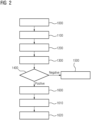
- Figure 2 illustrates a method of controlling the dispensing of gas to storages 6. This could apply to a gas production plant 1 such as illustrated in figure 1 where the gas is feed to a selectable of a plural of dispensers 5.
- the method includes, if there is an available dispenser 1000, to connect 1100 a gas storage 6, 6.1-6.5 with available storage capacity to the available dispenser 5 and to start a filling sequence 1200.
- the filling sequence 1200 includes a step of
- the safety check 1400 could include a variety of tests, such as flush and leak tests.
- a test procedure may be initiated, such as by the controller 7.
- a plural of storages 6 may be connected to the dispensers 5 at any time, though only one may be active in being filled, the rest waiting according to the scheme dictated by the queue. If any of these connections expected to be in waiting position, or any of the paths formed by the conduits 10 to these connections, are untight, this could lead to a general undesired leak.
- the prioritization and storage of the filling request in the queue 1600 only will be done by positive test. This ensures tight connections of all storages 6 with filling requests in the queue. In other words, all stored filling requests in the queue is known to relate to tight and safe connections of the dispensers 5 to storages 6.
- the method may include a step 1350 to send a safe mode signal once a filling request is received by the controller 7. See also the embodiment of figure 3 .
- the safe mode signal is sent to all the dispensers 5 with instruction for them to enter a safe mode state 1350 where all dispensers 5 are to be closed, and all filling of any storage 6 are to be stopped, corresponding to closing the flow generating device 4.
- a leak test 1400 positive result may - in addition to the step 1600 to prioritize the request and store it in a queue according to the priority - induce a signal to disengage safe mode state and start normal operation, including continuing the filling of a storage 6, thus opening the respective next dispenser 5.
- Figure 3 illustrates two versions of this embodiment.
- a signal is sent to disengage safe mode state and start normal operation, including continuing the filling of a storage 6, thus opening the respective dispenser 5.
- the step to prioritize the filling request and store it in a queue according to the priority 1600 could be before the step 1550 of sending a signal to disengage safe mode state and start normal operation, or (dashed arrow) to do both steps simultaneously.
- the safe mode may include for all valves between the electrolyzer 2, dispensers 5 and the flow generating device 4 to be closed.
- Figure 3 further illustrates, when the gas storage 6 being filled is registered to be full, initiating a step 1630 of deactivating the respective dispenser 5 and send the signal to activate the next dispenser 5,
- an expected filling time information is stored in the queue for each storage 6 with the filling request itself.
- the prioritizing thus may include an estimation of the time to fill the storage 6, and comparing it with all expected filling times in the queue.
- the available capacity in the storage 6.1 is smaller than other storages 6.2 and 6.3, it may be prioritized to earlier filling than these.
- a higher priority may be given to a storage 6.1 with a low comparable capacity compared to other storages 6.2, 6.3 in the queue. This for example enables prioritizing a quick filling of the storages 6 with low available capacity over those with a large available capacity. This ensures early departure of these freeing dispensers 5 for new storages 6...
- This is some embodiments means, that a storage 6 being filled when a new filling request is entered in the queue, suddenly may have lower priority and thus not the next to be filled. This is also enabled by the step 1350, the safe mode, where all dispensers 5 are closed making it irrelevant which storage 6 to fill next.
- time of arrival of the storage 6, or entry into the queue of a new filling request is also a parameter to be registered and used in the prioritizing.
- the number of times other requests has been inserted with higher priority is a further prioritization factor. This enables the introduction of a mechanism to ensure no storages 6 will wait in the queue for too long time compared to other storages 6. If a filling request for a storage 6 with a significant lower available capacity enters, the storage 6 already in the queue with the larger capacity may still be prioritized higher, if it has been bypassed a given number oof times etc.
- the method of estimating the time to fill the storage is based on registering the inner pressure of the storage. This is especially the case when all reservoirs 6 are known to have the same standardized size, the inner pressure indicating of they already are partly filled.
- the filling request e.g. includes information about the available storage 6 capacity.
- the prioritizing may include for the relative available capacities, time to fill the respective storages 6, time of arrival etc., according to some weight or algorithm taking the relative factors into consideration under some weights.
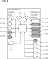
- Figure 4 illustrates a situation e.g. corresponding to that of figure 1 , where two of the dispensers 5.4, 5.5 are inactive (indicating e.g. the storage 6.5 has been filled and thus is e.g. ready to be removed). Thus, only three filling requests 10, 10.1, 10.2, 10.3 are stored in the queue in the controller 7, leaving two empty filling requests 10.4, 10.5 for the respective dispensers 5.4, 5.5.
- a positive signal to prepare dispenser 11, 11.1 only is present for the respective dispenser 5.1 whereto the storage 6.1 is being or to be filled next. Only this dispenser 5.1 has a positive safe mode signal 12, 12.1, the respective dispenser 5.1 being open or being prepared to open.
- the other dispensers 5.2-5.5 has a negative signal to prepare dispenser 11, 11.2-11.5, and a positive safe mode 12.2-12.5 signal (the respective dispensers 5, 5.2-5.5 thus being closed).
- a signal 14 indicates tank 3 is available e.g. as buffer if needed, or to feed gas from the tank 3.
- a filling request 10 When a filling request 10 is stored in the queue in the controller 7, it may come with a time stamp 13 etc. according to the embodiments previously described.
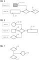
- a signal 15 may indicate off take of gas is available, as also illustrated in figure 5 .
- the queue, or the controller 7 with the queue reports ok for the first dispenser 5.1 to be prepared for dispensing 11.1 as it is not in safe mode 12.1.
- a signal 15 that offtake is available is issued to the flow generating device 4 to start the gas transfer.
- Figure 6 illustrates an embodiment requirement for the dispensers 5 to be prepared for dispensing 12.1, such as the first 5.1 dispenser of figures 1 and 5 , being the one in the queue 16, this having the highest priority.
- the dispensers 5 there needs to be a positive request for filling 10.1, and a signal that tank 3 is available as buffer 14 (having sufficient remaining storage capacity). Only then a prepare dispenser 12.1 signal will issued as ok.
- Figure 7 illustrates a further embodiment relevant to any of the previous embodiments.
- the final acceptance to send a start dispensing 18 signal is only issued if there is an available gas supply, meaning either there is a positive buffer signal 14 of gas availability or a positive signal 17 that the electrolyzer 2 is able to produce gas.
- the present invention relates to both the method to fill the storages 6 according the previous embodiments, as well as to the queue controller 7 to control the queue and register the entries, and to the system 1 including the electrolyzer 2, controller 7 and dispensers 5.
Landscapes
- Engineering & Computer Science (AREA)
- Mechanical Engineering (AREA)
- General Engineering & Computer Science (AREA)
- Filling Or Discharging Of Gas Storage Vessels (AREA)
Abstract
The present invention relates to a method to control the filling of a gas storage (6) with gas produced by a gas production plant (1) comprising a plural of selectable gas dispensers (5) and an electrolyzer (2) powered by a renewable energy source, the method including, if there is an available dispenser (5), connect a gas storage (6) with available storage capacity to the available dispenser (5) and start a filling sequence, the filling sequence including a step of
- signaling a filling request for the gas storage (6) to be filled, and when the gas storage (6) is connected to the available dispenser (5),
- conduct a safety check,
- by a negative safety check,
- end the filling sequence, and
- by a positive safety check,
- to prioritize the request and store it in a queue according to the priority,
- send a signal to for a next dispenser (5) to be activated being the one connected to the gas storage (6) with the highest priority filling request in the queue,
- activate the dispenser (5) connected to the gas storage (6)
- signaling a filling request for the gas storage (6) to be filled, and when the gas storage (6) is connected to the available dispenser (5),
- conduct a safety check,
- by a negative safety check,
- end the filling sequence, and
- by a positive safety check,
- to prioritize the request and store it in a queue according to the priority,
- send a signal to for a next dispenser (5) to be activated being the one connected to the gas storage (6) with the highest priority filling request in the queue,
- activate the dispenser (5) connected to the gas storage (6)
The present invention further relates to a controller operating the method.
Description
- The (present) invention relates to a method to control the filling of gas to movable storages, where the gas is produced by an electrolyzer powered by a renewable energy source, such as by wind turbines.
- Production of hydrogen from electrolysis using renewable energy is receiving massive attention and investments. The electrical grid has been continuously expanded for many years which allows to produce hydrogen from electrolysis at virtually any electrical connection.
- For many sites it is difficult or expensive to provide pipeline connection to the PtX facility, or they simply is not yet available.
- Here tube trailers are an attractive alternative. They break the chicken-and-egg dilemma by allowing for the transport of gas between any two road connected locations of production and consumption.
- They could provide either a permanent offtake or a temporary solution for a few years, until a gas pipeline is connected to the site.
- The gas from an electrolyzer is compressed for road transport up to several hundreds of bars. This is done using a compressor with a refueling dispenser which serves as an interface between the site and the mobile off-taker.
- The filling process of a high-capacity tube trailer is an operation that typically takes several hours due to gas flow limitations. Additionally, the availability and production rate of the electrolyzer may be less than 100% due to the intermittent power availability from the wind turbine.
- This means that the gas filling operation may be prolonged in windless conditions if no buffer storage is available on site.
- For a flexible operation of the off-taker logistics, the driver of the truck carrying the tube trailer should therefore
- 1. Arrive with an empty tube trailer ready for filling
- 2. Park and connect the empty tube trailer to a dispenser at the PtX facility and prepare it for filling
- 3. Depart with an already full tube trailer
- This trailer exchange should occur independently while a third tube trailer is undergoing the filling process where gas is delivered by the compressor.
- A driver arriving at a site with an empty tube trailer has a choice: Either manually abort the existing tube trailer filling (e.g. at 90% fill level) or wait for the tube trailer filling process to end. If the driver is too late then the gas production would eventually stop as no offtake is available.
- This imposes a strict timing of the arrival of the tube trailer driver or leads to prolonged waiting for the ongoing filling process to end. Tube trailers off-taker typically requires more flexibility, especially to transport tube trailers to and from a remote PtX site.
- The tube trailer fleet size poses an additional restriction to tube trailer availability, as well as number of drivers available.
- If multiple drivers arrive and connect tube trailers to dispensers at an offtake section where the filling process is ongoing, then they would all be filled simultaneously once the filling tube trailer was full. Connecting two tube trailers has great safety implications as any pressure balancing between the two large capacity vessels would lead to rapid gas flow and heat exchange. Additionally, it would double the time to fill a tube trailer if two are being filled simultaneously. Furthermore, the added gas storage of two filling trailers also carries added risk and complexity compared to filling only one tube trailer at a time. Furthermore, if a single compressor is to fill a plural of trailers it could require a significant pressure, especially if some or all the reservoirs are close to being full and thus offering a significant counter-pressure. A substantial large or a plural of compressors then would be required increasing the prize etc.
- Typically, drivers would prefer to arrive in the day times and connect the tube trailers to the dispensers at the offtake section. Here a tube trailer is first flushed, and leak tested until it is ready for filling. Only the filling step requires compressor action. Each tube trailer is connected to a dedicated dispenser. However, drivers need to wait before manually to start the filling process.
- The compressor may stop during filling for many reasons, e.g. if gas production is paused and no gas buffer is available.
- The waiting dispensers could then potentially engage in filling as the compressor stop could be interpreted as filling complete. This would result in an opening of valves at several dispensers with the risk of violent gas transfer during pressure balancing of the tube trailer gas vessels. Additionally, gas transfer to the filling trailer would stop as gas always flows into the trailer at the lowest pressure.
- For an example, if an offtake section consisted of 6 dispensers, then this could be accomplished by two subsections of three dispensers and each sub-section with its dedicated compressor, i.e. two compressors in total.
- The invention aims to solve the above problems, such as where one or multiple tube trailer arrive at a PtX site, how they are to be prepared for filling and how this is managed by a central control system.
- The object of the invention is achieved by the independent claims. The dependent claims describe advantageous developments and modifications of the invention.
- In accordance with the invention there is provided a method to control the filling of a gas storage with gas produced by a gas production plant comprising a plural of selectable gas dispensers and an electrolyzer powered by a renewable energy source, the method including, if there is an available dispenser, connect a gas storage with available storage capacity to the available dispenser and start a filling sequence, the filling sequence including a step of
- signaling a filling request for the gas storage to be filled, and when the gas storage is connected to the available dispenser,
- conduct a safety check,
- by a negative safety check,
- end the filling sequence, and
- by a positive safety check,
- to prioritize the request and store it in a queue according to the priority,
- send a signal to for a next dispenser to be activated being the one connected to the gas storage with the highest priority filling request in the queue,
- activate the dispenser connected to the gas storage.
- Each filling request prioritized and stored in the queue thus is associated with a specific gas storage.
- The gas reservoir could be connected the available dispenser before sending the filling request. This could be enabled by the available dispenser known to be closed, thus allowing safe connection.
- In an alternative embodiment, the filling request is sent before the connection. This could e.g., be the operator being informed the dispenser now is available for connection, or the connection is only made possible once a signal is given the dispenser is ready for connection.
- The method may include, when the filling of a gas storage is active, registering when it is full, then initiating the steps of deactivating the respective dispenser and send the signal to activate the next dispenser. Again, by the next dispenser is referred to the dispenser connected to the gas storage with the highest priority filling request in the queue.
- The step of prioritizing may include an estimate of the time to fill the storage, this could include for a higher priority to be given to a storage with a low comparable capacity compared to other storages in the queue.
- In one embodiment the method to estimate the time to fill the storage is based on registering the inner pressure of the storage.
- The step of prioritizing may include the time of arrival compared to other storages in the queue.
- The step of prioritizing may include a weighted combination of the time to fill the storage and the time of arrival.
- The dispensers may be connected to a shared flow generating device for feeding gas to the dispensers. The flow generating device may be a compressor.
- By using a single shared flow generating device offers the advantage to reduce cost and using the concept of only filling one storage at a time according to a prioritized queue enables the use of a smaller and cheaper device.
- The safety check may include flush and leak tests.
- In an embodiment, the filling sequence includes sending a safe mode signal to all the dispensers to enter a safe mode state including for all dispensers to be closed. Further the flow generating device may be closed, thus together ensuring no gas may leak to the new connection to be made between a dispenser and the new gas storage.
- In an embodiment, when the filling request is stored in the queue, a signal is sent to disengage safe mode state of the next dispenser to start normal operation of filling the connected storage. This then further may include starting the flow generating device.
- In the present context the safe mode is at least disengaged for the next dispenser set to start operation to fill the respective storage. The remaining of the dispensers may still be in safe mode to ensure they are fully closed.
- Safe mode may be repeatedly engaged and disengaged for the same dispenser as gas production is temporarily paused due to the intermittent gas production from the renewable power source.
- Safe mode where all dispensers, and optionally the flow generating device, is closed, allows the connection of the new gas storage to any available dispenser, since this will be known to be closed. This thus allows the connection of the gas storage to the available dispenser before or after sending the filling request.
- The safe mode may include for all valves between the electrolyzer and dispensers and the compressor to be closed. Further it may include for the flow generating device to be shut off.
- The present invention further relates to a central queue controller interfacing with a gas production plant comprising a plural of selectable gas dispensers and an electrolyzer powered by a renewable energy source, and where the queue control system is adapted to operate a filling sequence at the arrival of a new gas storage to be filled, the sequence including a step of
- signaling a filling request for the gas storage to be filled, and when the gas storage is connected to the available dispenser,
- conduct a safety check,
- by a negative safety check,
- end the filling sequence, and
- by a positive safety check,
- to prioritize the request and store it in a queue according to the priority,
- send a signal for a next dispenser to be activated being the one connected to the storage with the highest priority filling request in the queue,
- activate the dispenser connected to the gas storage.
- The queue controller may be adapted to operate according to the previous embodiments.
- Embodiments of the invention are now described, by way of example only, with reference to the accompanying drawings, of which:
- Figure 1
- shows a situation with four removable gas storages are connected to dispensers of a gas production plant.
- Figure 2
- shows a flow chart of a first embodiment method to control the gas dispensing to the gas storages.
- Figure 3
- shows a flow chart of a second embodiment method to control the gas dispensing to the gas storages.
- Figure 4
- shows a different settings or signals corresponding to the control of the situation of
figure 1 . - Figure 5
- shows embodiment requirements for a positive offtake available signal.
- Figure 6
- shows embodiment requirements for a positive prepare dispenser signal.
- Figure 7
- shows embodiment requirements for a positive gas available signal.
- The illustration in the drawings is in schematic form. It is noted that in different figures, similar or identical elements may be provided with the same reference signs.
- Although the present invention has been described in detail with reference to the preferred embodiment, it is to be understood that the present invention is not limited by the disclosed examples, and that numerous additional modifications and variations could be made thereto by a person skilled in the art without departing from the scope of the invention.
-
Figure 1 illustrates a gas production plant 1 powered by renewable power such as generated by a wind turbine, photovoltaic panels etc., or a combination thereof. - The
gas production plant 2 may include anelectrolyzer 2 and be adapted to produce hydrogen. It may also be adapted to extract CO2 from the atmosphere or for other gas production purposes. - In the present context, when referring to an
electrolyzer 2 this could be a system of a plural ofindividual electrolyzers 2. - The power output of such renewable plants is fluctuating leading to a fluctuating gas production, thus in some periods, none or a very low amount is outputted.
- In the illustrated embodiment, a set of conduits 8, such as tubes, pipes etc., connects the outlet of the
electrolyzer 2 to a plural of dispensers 5. In the embodiment five dispensers 5.1-5.5 is illustrated, but any number would apply. - The dispensers 5 are adapted to connect with storages 6, such as mobile storages like tanks or trailers to be transported by vessels like ships, trains, or trucks.
- In
figure 1 four storages 6, 6.1, 6.2, 6.3, 6.5 are seen connected to four of the dispensers, 5, 5.1, 5.2, 5.3, 5.5, whereas the last of the dispensers 5.4 in the illustrated situation is available for a new storage 6 to be connected when arriving. - One of the storages, 5.1, is seen to be partly filled, whereas two are 6.2, 6.3 are empty. The fourth tanker 6.5 are filled with gas.
- The figure could illustrate a situation where the fourth storage 6.5 has just been filled and is about to be removed. One of the respectively partly filled storage 6.1 or one of the empty storages 6.2, 6.3 then has the filling request in the queue with the highest priority. The dispenser 5, 5.1, 5.2, 5.3 connected thereto then is the next dispenser 5, 5.1, 5.2, 5.3 to be activated, or opened allowing the filling of the respective storages 6, 6.1, 6.2, 6.3.
- It could also be the partly filled storage 6.1 is presently being filled, the dispenser 5.5 connected to the full storage 6.5 being closed, and the storage 6.5 being ready for or being prepared for collection.
- The gas flow to the dispensers 5 is driven by a
flow generating device 4, such as e.g. a compressor. - In one embodiment a plural of individual dispensers 5 are shared by a single
flow generating device 4 for feeding gas to the all the dispensers 5. One singleflow generating device 4 thus is adapted to feed gas to a plural of selectable dispensers 5. - In addition (not illustrated) valves are positioned to open and close different conduits 8 and possible other parts.
- A more stationary tank 3 may be positioned, either intermediate the path from the
electrolyzer 2 to the dispensers 5, or as illustrated, at a branch of the conduits 10. This enables for example collection gas produced when no storages 6 are connected to the dispensers 5, and/or during connection of a new one, thus allowing continued operation of theelectrolyzer 2. - A
controller 7 is connected to control the gas production plant 1 and the dispensers 5. - The
controller 7 is adapted to operate according to a method to control the filling of a gas storage as also illustrated in the flow charts offigure 2 and3 . It is also adapted to include and control a prioritized queue as will be apparent below and can therefore also be referred to as aqueue controller 7. -
Figure 2 illustrates a method of controlling the dispensing of gas to storages 6. This could apply to a gas production plant 1 such as illustrated infigure 1 where the gas is feed to a selectable of a plural of dispensers 5. - The method includes, if there is an
available dispenser 1000, to connect 1100 a gas storage 6, 6.1-6.5 with available storage capacity to the available dispenser 5 and to start afilling sequence 1200. - The
filling sequence 1200 includes a step of - signaling a request for the gas storage to be filled 1300
- conduct a
safety check 1400, - by a negative safety check,
- end the
filling sequence 1500, and
- end the
- by a positive safety check,
- to prioritize the request and store it in a queue according to the
priority 1600, - send a signal to activate the next dispenser 5 in the
queue 1610, - start filling the
gas storage 1620.
- to prioritize the request and store it in a queue according to the
- The
safety check 1400 could include a variety of tests, such as flush and leak tests. When the storage 6 is connected to the dispenser 5 a test procedure may be initiated, such as by thecontroller 7. - In the present invention a plural of storages 6 may be connected to the dispensers 5 at any time, though only one may be active in being filled, the rest waiting according to the scheme dictated by the queue. If any of these connections expected to be in waiting position, or any of the paths formed by the conduits 10 to these connections, are untight, this could lead to a general undesired leak.
- However, in the present invention the prioritization and storage of the filling request in the
queue 1600 only will be done by positive test. This ensures tight connections of all storages 6 with filling requests in the queue. In other words, all stored filling requests in the queue is known to relate to tight and safe connections of the dispensers 5 to storages 6. - Having made the checks, a safe filling of a storage 6 then can be continued.
- Of the same safety reasons, the method may include a
step 1350 to send a safe mode signal once a filling request is received by thecontroller 7. See also the embodiment offigure 3 . - The safe mode signal is sent to all the dispensers 5 with instruction for them to enter a
safe mode state 1350 where all dispensers 5 are to be closed, and all filling of any storage 6 are to be stopped, corresponding to closing theflow generating device 4. - This has several purposes. For one, if an untightens exists somewhere, then no accidents can occur due to the combination of filling one storage 6 and connecting a new storage 6. For a second, it enables a safe connection of the new storage 6 without the risk of being compromised with gas within the system due to the filling of a storage 6. It also enables a
safe safety check 1400. - A
leak test 1400 positive result may - in addition to thestep 1600 to prioritize the request and store it in a queue according to the priority - induce a signal to disengage safe mode state and start normal operation, including continuing the filling of a storage 6, thus opening the respective next dispenser 5. -
Figure 3 illustrates two versions of this embodiment. For astep 1550, once the request for the gas storage to be filled is stored in the queue, or at least at apositive leak test 1400, a signal is sent to disengage safe mode state and start normal operation, including continuing the filling of a storage 6, thus opening the respective dispenser 5. - In
figure 3 both possibilities are illustrated. The step to prioritize the filling request and store it in a queue according to thepriority 1600 could be before thestep 1550 of sending a signal to disengage safe mode state and start normal operation, or (dashed arrow) to do both steps simultaneously. - The safe mode may include for all valves between the
electrolyzer 2, dispensers 5 and theflow generating device 4 to be closed. -
Figure 3 further illustrates, when the gas storage 6 being filled is registered to be full, initiating a step 1630 of deactivating the respective dispenser 5 and send the signal to activate the next dispenser 5, - In an embodiment, an expected filling time information is stored in the queue for each storage 6 with the filling request itself. The prioritizing thus may include an estimation of the time to fill the storage 6, and comparing it with all expected filling times in the queue.
- For example, in relation to the situation of
figure 1 , if the available capacity in the storage 6.1 is smaller than other storages 6.2 and 6.3, it may be prioritized to earlier filling than these. Thus, a higher priority may be given to a storage 6.1 with a low comparable capacity compared to other storages 6.2, 6.3 in the queue. This for example enables prioritizing a quick filling of the storages 6 with low available capacity over those with a large available capacity. This ensures early departure of these freeing dispensers 5 for new storages 6... - This is some embodiments means, that a storage 6 being filled when a new filling request is entered in the queue, suddenly may have lower priority and thus not the next to be filled. This is also enabled by the
step 1350, the safe mode, where all dispensers 5 are closed making it irrelevant which storage 6 to fill next. - In one embodiment time of arrival of the storage 6, or entry into the queue of a new filling request, is also a parameter to be registered and used in the prioritizing.
- Alternatively, or additionally, the number of times other requests has been inserted with higher priority is a further prioritization factor. This enables the introduction of a mechanism to ensure no storages 6 will wait in the queue for too long time compared to other storages 6. If a filling request for a storage 6 with a significant lower available capacity enters, the storage 6 already in the queue with the larger capacity may still be prioritized higher, if it has been bypassed a given number oof times etc.
- In one embodiment, the method of estimating the time to fill the storage is based on registering the inner pressure of the storage. This is especially the case when all reservoirs 6 are known to have the same standardized size, the inner pressure indicating of they already are partly filled.
- In other embodiments the filling request e.g. includes information about the available storage 6 capacity.
- The prioritizing may include for the relative available capacities, time to fill the respective storages 6, time of arrival etc., according to some weight or algorithm taking the relative factors into consideration under some weights.
-
Figure 4 illustrates a situation e.g. corresponding to that offigure 1 , where two of the dispensers 5.4, 5.5 are inactive (indicating e.g. the storage 6.5 has been filled and thus is e.g. ready to be removed). Thus, only three filling requests 10, 10.1, 10.2, 10.3 are stored in the queue in thecontroller 7, leaving two empty filling requests 10.4, 10.5 for the respective dispensers 5.4, 5.5. - In the same manner, a positive signal to prepare dispenser 11, 11.1 only is present for the respective dispenser 5.1 whereto the storage 6.1 is being or to be filled next. Only this dispenser 5.1 has a positive
safe mode signal 12, 12.1, the respective dispenser 5.1 being open or being prepared to open. The other dispensers 5.2-5.5 has a negative signal to prepare dispenser 11, 11.2-11.5, and a positive safe mode 12.2-12.5 signal (the respective dispensers 5, 5.2-5.5 thus being closed). - A
signal 14 indicates tank 3 is available e.g. as buffer if needed, or to feed gas from the tank 3. - When a filling request 10 is stored in the queue in the
controller 7, it may come with atime stamp 13 etc. according to the embodiments previously described. - A
signal 15 may indicate off take of gas is available, as also illustrated infigure 5 . The queue, or thecontroller 7 with the queue, reports ok for the first dispenser 5.1 to be prepared for dispensing 11.1 as it is not in safe mode 12.1. Hence, asignal 15 that offtake is available is issued to theflow generating device 4 to start the gas transfer. -
Figure 6 illustrates an embodiment requirement for the dispensers 5 to be prepared for dispensing 12.1, such as the first 5.1 dispenser offigures 1 and5 , being the one in thequeue 16, this having the highest priority. In addition, there needs to be a positive request for filling 10.1, and a signal that tank 3 is available as buffer 14 (having sufficient remaining storage capacity). Only then a prepare dispenser 12.1 signal will issued as ok. -
Figure 7 illustrates a further embodiment relevant to any of the previous embodiments. Here the final acceptance to send a start dispensing 18 signal is only issued if there is an available gas supply, meaning either there is apositive buffer signal 14 of gas availability or apositive signal 17 that theelectrolyzer 2 is able to produce gas. - The present invention relates to both the method to fill the storages 6 according the previous embodiments, as well as to the
queue controller 7 to control the queue and register the entries, and to the system 1 including theelectrolyzer 2,controller 7 and dispensers 5.
Claims (15)
- Method to control the filling of a gas storage (6) with gas produced by a gas production plant (1) comprising a plural of selectable gas dispensers (5) and an electrolyzer (2) powered by a renewable energy source, the method including, if there is an available dispenser (5), connect a gas storage (6) with available storage capacity to the available dispenser (5) and start a filling sequence, the filling sequence including a step of- signaling a filling request for the gas storage (6) to be filled, and when the gas storage (6) is connected to the available dispenser (5),- conduct a safety check,- by a negative safety check,- end the filling sequence, and- by a positive safety check,- to prioritize the request and store it in a queue according to the priority,- send a signal to for a next dispenser (5) to be activated being the one connected to the gas storage (6) with the highest priority filling request in the queue,- activate the dispenser (5) connected to the gas storage (6).
- Method according to claim 1, wherein the method includes, when the filling of a gas storage (6) is active, registering when it is full, then initiating the steps of deactivating the respective dispenser (5) and send the signal to activate the next dispenser (5).
- Method according to claim 1 or 2, wherein the step of prioritizing includes an estimate of the time to fill the storage (6).
- Method according to claim 3, wherein a higher priority is given to a storage (6) with a low comparable capacity compared to other storages (6) in the queue.
- Method according to claim 3 or 4, wherein the method estimating the time to fill the storage is based on registering the inner pressure of the storage (6).
- Method according to claim 1 or 2, wherein the step of prioritizing includes the time of arrival compared to other storages (6) in the queue.
- Method according to claim 3 and 6, wherein the step of prioritizing includes a weighted combination of the time to fill the storage (6) and the time of arrival.
- Method according to any of the previous claims, wherein the dispensers (5) are connected to a shared flow generating device (4) for feeding gas to the dispensers (5).
- Method according to claim 8, wherein the flow generating device (4) is a compressor.
- Method according to any of the previous claims, wherein the safety check includes flush and leak tests.
- Method according to any of the previous claims, wherein the filling sequence includes sending a safe mode signal to all the dispensers (5) to enter a safe mode state including for all dispensers (5) to be closed.
- Method according to claim 11, wherein, when the refilling request is stored in the queue, a signal is sent to disengage safe mode state of the next dispenser (5) to start normal operation of filling the connected storage (6).
- Method according to claim 11 or 12, wherein the safe mode includes for all valves between the electrolyzer (2) and dispensers (5) to be closed.
- A central queue controller (7) interfacing with a gas production plant (1) comprising a plural of selectable gas dispensers (5) and an electrolyzer (2) powered by a renewable energy source, and where the queue control (7) system is adapted to operate a filling sequence at the arrival of a new gas storage (6) to be filled, the sequence including a step of- signaling a filling request for the gas storage (6) to be filled, and when the gas storage (6) is connected to the available dispenser (5),- conduct a safety check,- by a negative safety check,- end the filling sequence, and- by a positive safety check,- to prioritize the request and store it in a queue according to the priority,- send a signal for a next dispenser 5) to be activated being the one connected to the storage (6) with the highest priority filling request in the queue,- activate the dispenser (5) connected to the gas storage (6).
- A central queue controller (7) according to claim 14, adapted to operate according to the method of any of the claims 1-13.
Priority Applications (2)
| Application Number | Priority Date | Filing Date | Title |
|---|---|---|---|
| EP23176083.6A EP4471317A1 (en) | 2023-05-30 | 2023-05-30 | Method to control the filling of movable gas storages |
| PCT/EP2024/061835 WO2024245671A1 (en) | 2023-05-30 | 2024-04-30 | Method to control the filling of movable gas storages |
Applications Claiming Priority (1)
| Application Number | Priority Date | Filing Date | Title |
|---|---|---|---|
| EP23176083.6A EP4471317A1 (en) | 2023-05-30 | 2023-05-30 | Method to control the filling of movable gas storages |
Publications (1)
| Publication Number | Publication Date |
|---|---|
| EP4471317A1 true EP4471317A1 (en) | 2024-12-04 |
Family
ID=86609871
Family Applications (1)
| Application Number | Title | Priority Date | Filing Date |
|---|---|---|---|
| EP23176083.6A Withdrawn EP4471317A1 (en) | 2023-05-30 | 2023-05-30 | Method to control the filling of movable gas storages |
Country Status (2)
| Country | Link |
|---|---|
| EP (1) | EP4471317A1 (en) |
| WO (1) | WO2024245671A1 (en) |
Citations (7)
| Publication number | Priority date | Publication date | Assignee | Title |
|---|---|---|---|---|
| JP4557638B2 (en) * | 2004-08-26 | 2010-10-06 | トキコテクノ株式会社 | Gas filling station management system |
| US20170023180A1 (en) * | 2015-04-24 | 2017-01-26 | Cmd Corporation | Method and Apparatus for Dispensing Gaseous Fuel To A Vehicle |
| DE102016208889B4 (en) * | 2016-05-23 | 2018-03-08 | Enno Wagner | Plant for providing hydrogen and method for operating the plant |
| CN108031314A (en) * | 2017-12-11 | 2018-05-15 | 苏州金宏气体股份有限公司 | A kind of mixed gas preparation method |
| WO2018203656A1 (en) * | 2017-05-02 | 2018-11-08 | (주)메타비스타 | Integrated fuel charging system |
| CN113085622A (en) * | 2021-03-15 | 2021-07-09 | 河南恒聚新能源设备有限公司 | Wind, light, electricity, hydrogen storage integrated charging and hydrogen charging system for electric automobile on highway |
| US20220252222A1 (en) * | 2017-12-13 | 2022-08-11 | J-W Power Company | System and Method for Priority CNG Filling |
-
2023
- 2023-05-30 EP EP23176083.6A patent/EP4471317A1/en not_active Withdrawn
-
2024
- 2024-04-30 WO PCT/EP2024/061835 patent/WO2024245671A1/en not_active Ceased
Patent Citations (7)
| Publication number | Priority date | Publication date | Assignee | Title |
|---|---|---|---|---|
| JP4557638B2 (en) * | 2004-08-26 | 2010-10-06 | トキコテクノ株式会社 | Gas filling station management system |
| US20170023180A1 (en) * | 2015-04-24 | 2017-01-26 | Cmd Corporation | Method and Apparatus for Dispensing Gaseous Fuel To A Vehicle |
| DE102016208889B4 (en) * | 2016-05-23 | 2018-03-08 | Enno Wagner | Plant for providing hydrogen and method for operating the plant |
| WO2018203656A1 (en) * | 2017-05-02 | 2018-11-08 | (주)메타비스타 | Integrated fuel charging system |
| CN108031314A (en) * | 2017-12-11 | 2018-05-15 | 苏州金宏气体股份有限公司 | A kind of mixed gas preparation method |
| US20220252222A1 (en) * | 2017-12-13 | 2022-08-11 | J-W Power Company | System and Method for Priority CNG Filling |
| CN113085622A (en) * | 2021-03-15 | 2021-07-09 | 河南恒聚新能源设备有限公司 | Wind, light, electricity, hydrogen storage integrated charging and hydrogen charging system for electric automobile on highway |
Also Published As
| Publication number | Publication date |
|---|---|
| WO2024245671A1 (en) | 2024-12-05 |
Similar Documents
| Publication | Publication Date | Title |
|---|---|---|
| EP3911889B1 (en) | Large-scale hydrogen refueling station | |
| US5406988A (en) | Method and apparatus for dispensing compressed gas into a vehicle | |
| US6779568B2 (en) | Gas distribution system | |
| US20230359155A1 (en) | Computer system and method providing operating instructions for thermal control of a blast furnace | |
| US12613001B2 (en) | MEGC trailer | |
| US7325561B2 (en) | Hydrogen vehicle gas utilization and refueling system | |
| Honselaar et al. | Hydrogen refuelling stations in the Netherlands: An intercomparison of quantitative risk assessments used for permitting | |
| CN201475634U (en) | Lng receiving station | |
| CN118582658A (en) | A comprehensive hydrogen source hydrogenation station and its control method and control system | |
| CN109237296A (en) | A kind of hydrogen supply method and system applied to hydrogenation stations | |
| CN114526442B (en) | Hydrogenation system and method based on gas discharge column control | |
| CN119468035A (en) | Hydrogen refueling station and method for filling hydrogen storage bottle group at hydrogen refueling station | |
| WO2024245671A1 (en) | Method to control the filling of movable gas storages | |
| CN113864635A (en) | Small storage tank gas supply method and system | |
| CN113623534A (en) | Emergency hydrogen filling system and method | |
| US12043227B2 (en) | Multi-receptacle fuel filling and storage system and method of using the same | |
| WO2023179832A1 (en) | Self-supplied hydrogen tube trailer | |
| CN115507294A (en) | LNG reserve station unloading method and system based on DCS | |
| US12209708B2 (en) | Pressure storage device for storing a medium, and method for operating a pressure storage device | |
| CN215862879U (en) | Emergency hydrogen supply control system | |
| EP3862314A1 (en) | Method for operating hydrogen production apparatus, and control device for hydrogen production apparatus | |
| CN118548438A (en) | Liquid hydrogen filling system and method | |
| CN116293415B (en) | Natural gas recovery system | |
| CN119611803B (en) | A liquid rocket propellant filling system | |
| CN218494763U (en) | Automatic nitrogen filling maintenance control device for large-scale container in early arrival |
Legal Events
| Date | Code | Title | Description |
|---|---|---|---|
| PUAI | Public reference made under article 153(3) epc to a published international application that has entered the european phase |
Free format text: ORIGINAL CODE: 0009012 |
|
| STAA | Information on the status of an ep patent application or granted ep patent |
Free format text: STATUS: THE APPLICATION HAS BEEN PUBLISHED |
|
| AK | Designated contracting states |
Kind code of ref document: A1 Designated state(s): AL AT BE BG CH CY CZ DE DK EE ES FI FR GB GR HR HU IE IS IT LI LT LU LV MC ME MK MT NL NO PL PT RO RS SE SI SK SM TR |
|
| STAA | Information on the status of an ep patent application or granted ep patent |
Free format text: STATUS: THE APPLICATION IS DEEMED TO BE WITHDRAWN |
|
| 18D | Application deemed to be withdrawn |
Effective date: 20250605 |