EP4471311A1 - Individual air supply duct and individual air supply assembly - Google Patents
Individual air supply duct and individual air supply assembly Download PDFInfo
- Publication number
- EP4471311A1 EP4471311A1 EP23176313.7A EP23176313A EP4471311A1 EP 4471311 A1 EP4471311 A1 EP 4471311A1 EP 23176313 A EP23176313 A EP 23176313A EP 4471311 A1 EP4471311 A1 EP 4471311A1
- Authority
- EP
- European Patent Office
- Prior art keywords
- air supply
- individual air
- supply duct
- individual
- service unit
- Prior art date
- Legal status (The legal status is an assumption and is not a legal conclusion. Google has not performed a legal analysis and makes no representation as to the accuracy of the status listed.)
- Pending
Links
Images





Classifications
-
- F—MECHANICAL ENGINEERING; LIGHTING; HEATING; WEAPONS; BLASTING
- F16—ENGINEERING ELEMENTS AND UNITS; GENERAL MEASURES FOR PRODUCING AND MAINTAINING EFFECTIVE FUNCTIONING OF MACHINES OR INSTALLATIONS; THERMAL INSULATION IN GENERAL
- F16L—PIPES; JOINTS OR FITTINGS FOR PIPES; SUPPORTS FOR PIPES, CABLES OR PROTECTIVE TUBING; MEANS FOR THERMAL INSULATION IN GENERAL
- F16L3/00—Supports for pipes, cables or protective tubing, e.g. hangers, holders, clamps, cleats, clips, brackets
- F16L3/01—Supports for pipes, cables or protective tubing, e.g. hangers, holders, clamps, cleats, clips, brackets for supporting or guiding the pipes, cables or protective tubing, between relatively movable points, e.g. movable channels
- F16L3/012—Supports for pipes, cables or protective tubing, e.g. hangers, holders, clamps, cleats, clips, brackets for supporting or guiding the pipes, cables or protective tubing, between relatively movable points, e.g. movable channels using reels
-
- B—PERFORMING OPERATIONS; TRANSPORTING
- B64—AIRCRAFT; AVIATION; COSMONAUTICS
- B64D—EQUIPMENT FOR FITTING IN OR TO AIRCRAFT; FLIGHT SUITS; PARACHUTES; ARRANGEMENT OR MOUNTING OF POWER PLANTS OR PROPULSION TRANSMISSIONS IN AIRCRAFT
- B64D13/00—Arrangements or adaptations of air-treatment apparatus for aircraft crew or passengers, or freight space
-
- B—PERFORMING OPERATIONS; TRANSPORTING
- B64—AIRCRAFT; AVIATION; COSMONAUTICS
- B64D—EQUIPMENT FOR FITTING IN OR TO AIRCRAFT; FLIGHT SUITS; PARACHUTES; ARRANGEMENT OR MOUNTING OF POWER PLANTS OR PROPULSION TRANSMISSIONS IN AIRCRAFT
- B64D13/00—Arrangements or adaptations of air-treatment apparatus for aircraft crew or passengers, or freight space
- B64D13/06—Arrangements or adaptations of air-treatment apparatus for aircraft crew or passengers, or freight space the air being conditioned
-
- B—PERFORMING OPERATIONS; TRANSPORTING
- B64—AIRCRAFT; AVIATION; COSMONAUTICS
- B64D—EQUIPMENT FOR FITTING IN OR TO AIRCRAFT; FLIGHT SUITS; PARACHUTES; ARRANGEMENT OR MOUNTING OF POWER PLANTS OR PROPULSION TRANSMISSIONS IN AIRCRAFT
- B64D13/00—Arrangements or adaptations of air-treatment apparatus for aircraft crew or passengers, or freight space
- B64D2013/003—Cabin ventilation nozzles
-
- B—PERFORMING OPERATIONS; TRANSPORTING
- B64—AIRCRAFT; AVIATION; COSMONAUTICS
- B64D—EQUIPMENT FOR FITTING IN OR TO AIRCRAFT; FLIGHT SUITS; PARACHUTES; ARRANGEMENT OR MOUNTING OF POWER PLANTS OR PROPULSION TRANSMISSIONS IN AIRCRAFT
- B64D13/00—Arrangements or adaptations of air-treatment apparatus for aircraft crew or passengers, or freight space
- B64D13/06—Arrangements or adaptations of air-treatment apparatus for aircraft crew or passengers, or freight space the air being conditioned
- B64D2013/0603—Environmental Control Systems
- B64D2013/0625—Environmental Control Systems comprising means for distribution effusion of conditioned air in the cabin
-
- B—PERFORMING OPERATIONS; TRANSPORTING
- B64—AIRCRAFT; AVIATION; COSMONAUTICS
- B64D—EQUIPMENT FOR FITTING IN OR TO AIRCRAFT; FLIGHT SUITS; PARACHUTES; ARRANGEMENT OR MOUNTING OF POWER PLANTS OR PROPULSION TRANSMISSIONS IN AIRCRAFT
- B64D13/00—Arrangements or adaptations of air-treatment apparatus for aircraft crew or passengers, or freight space
- B64D13/06—Arrangements or adaptations of air-treatment apparatus for aircraft crew or passengers, or freight space the air being conditioned
- B64D2013/0603—Environmental Control Systems
- B64D2013/0688—Environmental Control Systems with means for recirculating cabin air
-
- B—PERFORMING OPERATIONS; TRANSPORTING
- B64—AIRCRAFT; AVIATION; COSMONAUTICS
- B64D—EQUIPMENT FOR FITTING IN OR TO AIRCRAFT; FLIGHT SUITS; PARACHUTES; ARRANGEMENT OR MOUNTING OF POWER PLANTS OR PROPULSION TRANSMISSIONS IN AIRCRAFT
- B64D2231/00—Emergency oxygen systems
- B64D2231/02—Supply or distribution systems
Definitions
- the present disclosure provides an individual air supply duct for connecting a main air supply duct to a passenger service unit in an aircraft, and an individual air supply assembly with such air supply duct.
- An individual air supply duct is located in proximity to the overhead storage compartments of an aircraft. Generally, several individual air supply ducts are connected to each other to form an individual air supply duct line. This individual air supply duct line has the sole purpose of leading air from riser ducts, which are connected to main air supply ducts, to gaspers of individual air panels of passenger service units located above passenger seats.
- an individual air supply duct is made of a rigid material and has the shape of a straight circular-cylindrical pipe with port structures protruding in pairs laterally from the outer surface of the individual air supply duct at different angles.
- the angles are such that the two port structures of each port structure pair protrude away from each other symmetrically to a cross-sectional plane of the individual air supply duct, wherein said cross-sectional plane is orthogonal to the longitudinal extension direction of the straight circular-cylindrical pipe.
- Gaspers of an individual air panel of a passenger service unit are connected to a single rigid common manifold, which is connected to at least one of the port structures of at least one individual air supply duct via a flexible hose.
- the problem to be solved is to improve the above described current solution. This can be done by reducing at least one of the solution's complexity, weight and overall costs.
- An alternative individual air supply duct is not manufactured by extrusion. It can be manufactured by another well-known manufacturing process.
- the individual air supply duct wherein the individual air supply duct comprises a cross-section, which is orthogonal to the longitudinal extension direction, with a circular inner circumference.
- the inner circumference may not be circular.
- the cross-section lies in a plane that is orthogonal to the longitudinal extension direction, which may be a direction in an x-axis.
- the cross-sectional plane may lie in a yz-plane, which extends in a y-axis and a z-axis direction.
- the individual air supply duct may comprise a straight circular-cylindrical pipe, which forms an inner portion of the individual air supply duct.
- An outer portion of the individual air supply duct may extend radially outward from the inner portion to at least partially circumscribe the inner portion.
- the longitudinal extension direction is the longitudinal extension direction of the individual air supply duct.
- the longitudinal extension direction may be a direction in an x-axis.
- the individual air supply duct wherein the individual air supply duct comprises a cross-section, which is orthogonal to the longitudinal extension direction, with a curved outer surface portion, which includes the outer rail structure.
- the outer portion may comprise the outer rail structure.
- the curved outer surface portion may not be curved.
- the cross-section lies in a plane that is orthogonal to the longitudinal extension direction, which may be a direction in an x-axis.
- the cross-sectional plane may lie in a yz-plane, which extends in a y-axis and a z-axis direction.
- the curved outer surface portion may have a constant curvature radius.
- the curved outer surface portion may be semicircular.
- the outer rail structure may be formed by a gap in the outer surface portion.
- the gap may be formed in the center of the outer surface portion.
- the longitudinal center of the gap may lie in an xy-plane, in which the centerline of the individual air supply duct lies.
- the gap may cross-sectionally extend to form an open recess in the individual air supply duct.
- the open recess may be symmetrical to an xy-plane, in which the centerline of the individual air supply duct lies, e.g. it may be T-shaped.
- the individual air supply duct wherein the individual air supply duct comprises an edge for attachment of a passenger service unit or a spacer element.
- the edge may form a snap and/or hinge part, to which a passenger service unit can be attached and, for example, pivoted around.
- the edge / attachment part may extend in parallel to the longitudinal direction of the individual air supply duct, e.g. in the longitudinal direction of the inner portion, i.e. in the direction of an x-axis. While the rail structure may be on one side of the individual air supply duct, the edge / attachment part may be on the opposite side of the individual air supply duct.
- the edge / attachment part may define a rotation axis in the direction of the x-axis that may be a fixed part of the individual air supply duct. Therefore, said rotation axis can be used as a y-axis and z-axis reference, e.g.
- the edge / attachment part may be configured to conduct electrical energy or signals, e.g. providing power supply, grounding or signals, e.g. for an interlock test or an emergency oxygen mask container opening.
- the individual air supply duct wherein the individual air supply duct comprises individual connection ports, being located on the outer surface of the individual air supply duct and at equal intervals along the individual air supply duct.
- the individual air supply duct may comprise an inner portion with a centerline, wherein the inner portion may be a straight circular-cylindrical pipe.
- the centerline may extend in the direction of an x-axis.
- Individual connection ports which may be circular through holes, are located on the outer surface of the inner portion. These individual connection ports may extend in parallel to each other, each along its own centerline in the direction of a y-axis, i.e. orthogonal to the centerline of the inner portion.
- the centerlines of the individual connection ports may intersect the centerline of the inner portion, i.e. the centerlines of the individual connection ports and the inner portion may lie in a common plane, i.e. an xy-plane.
- centerlines of the individual connection ports may be located at equal intervals in a direction of the longitudinal direction of the individual air supply duct, i.e. in the direction of the centerline of the inner portion, i.e. in the direction of the x-axis.
- the individual connection ports may be configured to provide a functional connection between the inside and the outside of the individual air supply duct and/or its inner portion.
- An individual air supply assembly comprising: the individual air supply duct, and a passenger service unit configured to be mounted thereto, wherein the individual air supply duct comprises individual connection ports, being located on the outer surface of the individual air supply duct and at equal intervals along the individual air supply duct, wherein the passenger service unit comprises a port, being located on the outer surface of the passenger service unit, and wherein, when the passenger service unit is mounted to the individual air supply duct, the port is brought into its closest proximity and/or into alignment with a corresponding connection port.
- the individual connection ports may be through holes or electrical contacts.
- the through holes may extend from the inside and the outside of the individual air supply duct.
- the electrical contacts may connect an electrical component on the inside of the individual air supply duct with the outside of the individual air supply duct.
- Mounted means that the passenger service unit is attached and in a mounted state relative to the individual air supply duct.
- the individual connection port may form the socket and the port may form the plug.
- the individual air supply assembly further comprising: at least one spacer element, wherein the spacer element is configured to be mounted to the individual air supply duct and to cover at least one of the individual connection ports, when the spacer element is mounted to the individual air supply duct.
- the spacer element may be similar in shape and dimensions, for example in the direction of the y-axis and z-axis, to the passenger service unit. However, it may lack any of the ports of the passenger service unit. It may be part of the individual air supply assembly.
- the spacer element may be configured to be mounted to the individual air supply duct and to cover at least one of the individual connection ports, when the spacer element is mounted to the individual air supply duct, i.e. attached and in the mounted state.
- the spacer element is configured to protect and/or seal the at least one individual connection port.
- the spacer element may comprise the sealant described below, which may be an integral part of the spacer element or attached to the spacer element.
- the individual air supply assembly wherein the individual air supply duct encloses at least one of: an emergency oxygen sub-duct, a fluid duct, a fiber optic cable, and/or an electrical cable.
- At least one of the emergency oxygen sub-duct, the fluid duct, the fiber optic cable, and/or the electrical cable is connected to at least one individual connection port.
- the attachment can be a permanent or non-permanent snap connection.
- a snap & click connection For example,
- An alternative individual air supply assembly may comprise: two individual air supply ducts, and a joint connector in between connecting the two individual air supply ducts.
- the joint connector may be flexible, i.e. stretchable and compressible and/or comprises a defined flexibility, in the longitudinal direction, i.e. in the direction of the x-axis, of the individual air supply ducts.
- the joint connector can fixedly or flexibly attach the two individual air supply ducts at different rotary angles about their colinear centerline.
- This alternative air supply assembly may further comprise feature of the air supply assembly previously described.
- a sealant may be provided between the individual air supply duct and the passenger service unit such that it surrounds the passage between their respective ports.
- a sealant may be attached to the passenger service unit and/or be attached to the individual air supply duct.
- the sealant can be any type of air impermeable or fluid impermeable sealant, for example a well-known plastic sealing ring. So, with the sealant being part of the individual air supply assembly and being sandwiched by the passenger service unit and the individual air supply duct in the mounted state of the passenger service unit, an automatic sealing is achieved in the mounted state of the passenger service unit.
- any features pertaining to the individual air supply duct and not to the passenger service unit or the spacer element may further define the individual air supply duct.
- An air supply tubing may include multiple interconnected individual air supply ducts or individual air supply assemblies. Further, an aircraft may include the air supply tubing, at least one of the individual air supply ducts or the individual air supply assemblies.
- Fig. 1 is a top view of a cross-section through an aircraft 1 showing individual air supply ducts 3 and riser ducts 5.
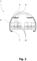
- Fig. 2 is a front view of a cross-section through the aircraft 1 illustrated in Fig. 1 showing the individual air supply ducts 3, the riser ducts 5 and additionally main supply ducts 7.
- the main supply ducts 7 extend through the aircraft underneath passenger seats of the aircraft 1.
- the riser ducts 5 extend from underneath the passenger seats to above the passenger seats to connect the main supply ducts 7 and the individual air supply ducts 3.
- the individual air supply ducts 3 extend above the passenger seats.
- the individual air supply ducts 3, the riser ducts 5 and the main supply ducts 7 are connected such that air can be supplied from the main supply ducts 7, further through the riser ducts 5 and the individual air supply ducts 3 to passenger service units 9 and gaspers 11 included therein, wherein the gaspers 11 are passenger adjustable air outlets situated above the passenger seats.
- the passenger service units 9 may comprise lights or other electric components in addition to or instead of the gaspers 11.
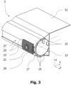
- Fig. 3 is a perspective top view of an individual air supply duct 3.
- the individual air supply duct 3 is an extruded profile with a longitudinal extension in the direction of an x-axis. Consequently, the extrusion direction of such individual air supply duct 3 is in the direction of the x-axis as well.
- the individual air supply duct 3 is a monolithic part, which has two functionally distinct portions, which will be described next.
- An outer portion 17 of the individual air supply duct 3 extends outward, here radially outward, from the inner portion 13 to at least partially or fully circumscribe the inner portion 13.
- the outer portion 17 has an ⁇ -like cross-section in the yz-plane and is connected to the inner portion 13 via ribs 19.
- a gap 21 in the outer portion 17 extending in the direction of the x-axis forms an open recess 23, which in this case is T-like in the yz-plane, wherein "like" means generally "shaped".
- the open recess 23 is symmetrical to the xy-plane, in which the centerlines of the inner portion 13 and the centerlines of the individual connection ports 15 lie.
- the individual connection ports 15 and the open recess 23 are on opposite sides of the individual air supply duct 3, here even on diametrically opposite sides of the individual air supply duct 3, i.e. the inner portion 13.
- two protrusions 25 are provided in the outer portion 17, wherein these protrusions 25 are symmetrical to said xy-plane and extend towards each other with equidistant ends to form a rail structure 27 extending in the direction of the x-axis.
- This rail structure 27 is configured to hold a slider 29, here a nut slider 29, movably in the direction of the x-axis.
- the slider 29 is configured to attach the individual air supply duct 3 to other structural components of the aircraft 1. It may provide such attachment in a loose form fit.
- Said slider 29 is configured to hold the individual air supply duct 3 such that the individual air supply duct 3 is only moveable along the direction of the x-axis.
- a plate 31 extending from an edge of the ⁇ -shaped outer portion 17 in a plane parallel to the above-mentioned xy-plane may or may not be provided.
- the individual air supply duct 3 comprises an outer rail structure 27 that extends along the longitudinal extension direction of the individual air supply duct 3, i.e. in the direction of the x-axis.
- the outer rail structure 27 is configured to provide a floating connection of the individual air supply duct 3 to other structural components of the aircraft 1 in the direction of the x-axis, which floating can compensate for a shrinkage in an aircraft 1.
- the individual air supply duct 3 comprises a cross-section, which is orthogonal to the longitudinal extension direction of the individual air supply duct 3, i.e. in the yz-plane, with a curved outer surface portion, which includes the outer rail structure 27.
- the curved outer surface portion may have a constant curvature radius.
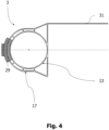
- Fig. 4 is a side view of the individual air supply duct 3 illustrated in Fig. 3 .
- the circular-cylindrical inner portion 13 and the ⁇ -like outer portion 17 are shown even better.
- the individual air supply duct 3 is ⁇ -like with a closed ⁇ basis and walls connecting the opposite ends of the ⁇ basis with the rest of the ⁇ body.
- Fig. 5 is a longitudinal cross-section through two of the individual air supply ducts 3, which are connected via a joint connector 33.
- the joint connector 33 comprises a male connector part 35, which is at least in the direction of the x-axis fixedly attached to the longitudinal end of one of the two colinear individual air supply ducts 3, and a female connector part 37, which is at least in the direction of the x-axis fixedly attached to the longitudinal end of the other one of the two colinear individual air supply ducts 3.
- the attachment can be a permanent or non-permanent snap connection. For example, a snap & click connection.
- the joint connector 33 connects the inner portions 13 of the individual air supply ducts 3, the circular-cylindrical shape of the inner portion 13 allows an easy and fast rotary connection and adjustment between two individual air supply ducts 3.
- two individual air supply ducts 3 can be fixedly or flexibly attached to each other by means of the joint connector 33 at different rotary angles about their colinear centerline.
- the joint connector 33 is flexible, i.e. stretchable and compressible and/or comprises a defined flexibility, in the longitudinal direction, i.e. in the direction of the x-axis, of the individual air supply ducts 3 it connects, so that it can compensate for movement of the individual air supply ducts 3 in said direction.
- Fig. 6 is the perspective top view of an individual air supply assembly 39 with the individual air supply duct 3 illustrated in Fig. 3 and the passenger service unit 9 that is partially shown, attached to the individual air supply duct 3 and in a mounted state.
- the attachment can be a permanent or non-permanent snap connection. For example, a snap & click connection. Permanent means that its removal will cause damage. Non-permanent means that its removal will not cause damage.
- the mounted state describes a state in which the passenger service unit 9 is in a fixed position relative to the individual air supply duct 3.
- the passenger service unit 9 is pivotably attached to an edge 43 of the ⁇ -shaped outer portion 17, which differs from the edge of the ⁇ -shaped outer portion 17, from which the plate 31 extends.
- the edge 43 / attachment part extends in parallel to the longitudinal direction of the individual air supply duct 3 and the inner portion 13, i.e. in the direction of the x-axis. While the rail structure 27 is on one side of the individual air supply duct 3, the edge 43 / attachment part is on the opposite side of the individual air supply duct 3.
- the edge 43 / attachment part defines a rotation axis in the direction of the x-axis that is a fixed part of the individual air supply duct 3. Therefore, said rotation axis can be used as a y-axis and z-axis reference, e.g. for installation and maintenance, for the passenger service unit 9. Additionally or alternatively, the edge 43 / attachment part may be configured to conduct electrical energy or signals.
- the individual air supply assembly 39 comprises: the individual air supply duct 3, and the passenger service unit 9 configured to be mounted thereto, wherein the individual air supply duct 3 comprises individual connection ports 15, being located on the outer surface of the individual air supply duct 3 and at equal intervals along the individual air supply duct 3, and wherein the passenger service unit 9 comprises a port 45 or at least one port, preferably 2 or more ports 45, being located on the outer surface of the passenger service unit 9, and wherein, when the passenger service unit 9 is mounted to the individual air supply duct 3, i.e. in a mounted state, the port 45/ports 45 is/are brought into its/their closest proximity and/or into alignment with a corresponding individual connection port 15/ corresponding individual connection ports 15.
- connection port 15 and the port 45 may be brought into contact with each other, when the passenger service unit 9 is in the mounted state. Thereby, a continuous air interface for air distribution to the passenger service units 9 independent from their position in the direction of the x-axis is provided.
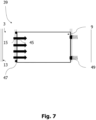
- Fig. 7 is a schematic top view of the individual air supply assembly 39 of Fig. 6 .
- the airflow between the individual connection ports 15 of the individual air supply duct 3 and the ports 45 of the passenger service unit 9 is shown by means of horizontal arrows, which indicated the airflow through each pair of their ports 15, 45.
- a sealant 47 is provided between the individual air supply duct 3 and the passenger service unit 9 such that it surrounds the passage between their respective ports 15, 45.
- the passenger service unit 9 is held in said mounted state by a locking mechanism 49, which is here in the form of a flexible locking pin or more specifically in the form of a spring supported locking pin.
- This locking mechanism 49 can be included in or attached to the individual air supply duct 3, e.g. by means of the plate 31 in Fig. 3 - see also Fig. 9 , which is described below.
- the locking mechanism 49 can be included in or attached to other components of an aircraft 1 - see Fig. 8 , which is described below.
- Fig. 8 is a schematic side view of the individual air supply assembly 39 of Fig. 7 , wherein the passenger service unit 9 is in the mounted state.
- This figure shows by means of the horizontal arrow that air from the individual air supply duct 3 enters the passenger service unit 9 through the ports 15, 45, the sealant 47 between the individual air supply duct 3 and the passenger service unit 9 surrounds the passage between their respective ports 15, 45.
- the locking mechanism 49 is configured such that it locks the passenger service unit 9 in its mounted state in a position relative to the individual air supply duct 3, wherein here the locking mechanism 49 is included in or attached to other components of an aircraft 1.
- Fig. 9 is a schematic side view of the individual air supply assembly 39 of Fig. 8 , wherein the passenger service unit 9 is in an unmounted state. In this state, the passenger service unit 9 can freely pivot relative to the individual air supply duct 3, here about the edge 43 of the individual air supply duct 3. While it is shown that the sealant 47 is attached to the passenger service unit 9, a sealant can alternatively or additionally be attached to the individual air supply duct 3.
- the sealant 47 can be any type of air impermeable or fluid impermeable sealant, for example a well-known plastic sealing ring.
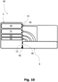
- Fig. 10 is a schematic side view of another individual air supply assembly 39 with another individual air supply duct 3 and the passenger service unit 9.
- This individual air supply duct 3 encloses an emergency oxygen sub-duct 49, a fluid duct 51, which can be a liquid duct, e.g. a water duct, a fiber optic cable 53 and/or an electrical cable 55.
- a fluid duct 51 which can be a liquid duct, e.g. a water duct, a fiber optic cable 53 and/or an electrical cable 55.
- Each of these components may comprise a suitable individual connection port 15 as part of the individual air supply duct 3, wherein the individual connection ports 15 may be through holes or electrical contacts.
- Corresponding ports 45 can achieve a connection with the respective individual connection ports 15, when the passenger service unit 9 is in its mounted state, as shown in Fig. 10 .
- an emergency oxygen supply for emergency oxygen piping to mask lanyards and/or a centralized oxygen system an electrical connection with electrical features, e.g. reading light power supply or loudspeaker signals, a piping connection for all kinds of fluids, e.g. water, and/or fiber optic cable connections with data signal functions, e.g. passenger information services.
- an electrical connection with electrical features e.g. reading light power supply or loudspeaker signals
- a piping connection for all kinds of fluids e.g. water
- fiber optic cable connections with data signal functions e.g. passenger information services.
- passenger service unit 9 when the passenger service unit 9 is in an unmounted state, for example by being pivoted about the edge 43 in a clockwise direction in Fig. 10 , all of the previously connected individual connection ports 15 may be disconnected.
- said ports 15, 45 may form a plug and socket connection, which is connected in the mounted state of the passenger service unit 9, as shown in Fig. 10 , and which is disconnected in the unmounted state of the passenger service unit
- the spacer element is similar in shape and dimensions, e.g. in the direction of the y-axis and z-axis, to the passenger service unit 9. However, it lacks any of the ports 45 of the passenger service unit 9. Its sole purpose is to fill a space in the direction of the x-axis following a passenger service unit 9. Therefore, its dimension in the direction of the x-axis may differ from that of the passenger service unit 9. It may further be part of the individual air supply assembly 39.
- the spacer element may be configured to be mounted to the individual air supply duct 3 and to cover at least one of the individual connection ports 15, when the spacer element is mounted to the individual air supply duct 3, i.e. attached and in the mounted state.
- the spacer element will protect and/or seal at least one individual connection port 15.
- the spacer element may comprise the sealant 47, which is an integral part of the spacer element or attached to the spacer element.
- the spacer element just like the passenger service unit 9, may be pivotable between an unmounted state, in which the spacer element can freely pivot relative to the individual air supply duct 3, and a mounted state, in which the spacer element is in a fixed position relative to the individual air supply duct 3.
- An air supply tubing may include multiple interconnected individual air supply ducts 3 or individual air supply assemblies 39. Further, an aircraft 1 may include the air supply tubing, at least one of the individual air supply ducts 3 or the individual air supply assemblies 39.
Landscapes
- Engineering & Computer Science (AREA)
- Health & Medical Sciences (AREA)
- General Health & Medical Sciences (AREA)
- Pulmonology (AREA)
- Aviation & Aerospace Engineering (AREA)
- General Engineering & Computer Science (AREA)
- Mechanical Engineering (AREA)
- Duct Arrangements (AREA)
Abstract
Individual air supply duct (3) for connecting a main air supply duct (7) to a passenger service unit (9) in an aircraft, wherein the duct (3) is an extruded profile with a longitudinal extension direction (x). Individual air supply assembly (39) comprising the duct (3) and a passenger service unit (9) configured to be mounted thereto, wherein the duct (3) comprises individual connection ports (15), being located on the outer surface of the duct (3) and at equal intervals along the duct (3), wherein the passenger service unit (9) comprises a port (45), being located on the outer surface of the passenger service unit (9), and wherein, when the passenger service unit (9) is mounted to the duct (3), the port (45) is brought into close proximity and into alignment with a corresponding connection port (15).
Description
- The present disclosure provides an individual air supply duct for connecting a main air supply duct to a passenger service unit in an aircraft, and an individual air supply assembly with such air supply duct.
- An individual air supply duct is located in proximity to the overhead storage compartments of an aircraft. Generally, several individual air supply ducts are connected to each other to form an individual air supply duct line. This individual air supply duct line has the sole purpose of leading air from riser ducts, which are connected to main air supply ducts, to gaspers of individual air panels of passenger service units located above passenger seats.
- Currently an individual air supply duct is made of a rigid material and has the shape of a straight circular-cylindrical pipe with port structures protruding in pairs laterally from the outer surface of the individual air supply duct at different angles. The angles are such that the two port structures of each port structure pair protrude away from each other symmetrically to a cross-sectional plane of the individual air supply duct, wherein said cross-sectional plane is orthogonal to the longitudinal extension direction of the straight circular-cylindrical pipe. Gaspers of an individual air panel of a passenger service unit are connected to a single rigid common manifold, which is connected to at least one of the port structures of at least one individual air supply duct via a flexible hose.
- The problem to be solved is to improve the above described current solution. This can be done by reducing at least one of the solution's complexity, weight and overall costs.
- The solution is provided by the claimed individual air supply duct and the claimed individual air supply assembly.
- In particular, the following provisions, describe embodiments according to the present invention:
- (1) An individual air supply duct for connecting a main air supply duct to a passenger service unit of an aircraft, wherein the individual air supply duct is an extruded profile with a longitudinal extension direction.
- An alternative individual air supply duct is not manufactured by extrusion. It can be manufactured by another well-known manufacturing process.
- The individual air supply duct, wherein the individual air supply duct comprises a cross-section, which is orthogonal to the longitudinal extension direction, with a circular inner circumference.
- Alternatively, the inner circumference may not be circular. The cross-section lies in a plane that is orthogonal to the longitudinal extension direction, which may be a direction in an x-axis. The cross-sectional plane may lie in a yz-plane, which extends in a y-axis and a z-axis direction.
- The individual air supply duct may comprise a straight circular-cylindrical pipe, which forms an inner portion of the individual air supply duct. An outer portion of the individual air supply duct may extend radially outward from the inner portion to at least partially circumscribe the inner portion.
- (2) The individual air supply duct, wherein the individual air supply duct comprises an outer rail structure extending along the longitudinal extension direction.
- The longitudinal extension direction is the longitudinal extension direction of the individual air supply duct. The longitudinal extension direction may be a direction in an x-axis.
- The individual air supply duct, wherein the individual air supply duct comprises a cross-section, which is orthogonal to the longitudinal extension direction, with a curved outer surface portion, which includes the outer rail structure. The outer portion may comprise the outer rail structure.
- Alternatively, the curved outer surface portion may not be curved. The cross-section lies in a plane that is orthogonal to the longitudinal extension direction, which may be a direction in an x-axis. The cross-sectional plane may lie in a yz-plane, which extends in a y-axis and a z-axis direction. The curved outer surface portion may have a constant curvature radius. The curved outer surface portion may be semicircular. The outer rail structure may be formed by a gap in the outer surface portion. The gap may be formed in the center of the outer surface portion. The longitudinal center of the gap may lie in an xy-plane, in which the centerline of the individual air supply duct lies. The gap may cross-sectionally extend to form an open recess in the individual air supply duct. The open recess may be symmetrical to an xy-plane, in which the centerline of the individual air supply duct lies, e.g. it may be T-shaped.
- (3) The individual air supply duct, wherein the individual air supply duct comprises an edge for attachment of a passenger service unit or a spacer element.
- The edge may form a snap and/or hinge part, to which a passenger service unit can be attached and, for example, pivoted around. The edge / attachment part may extend in parallel to the longitudinal direction of the individual air supply duct, e.g. in the longitudinal direction of the inner portion, i.e. in the direction of an x-axis. While the rail structure may be on one side of the individual air supply duct, the edge / attachment part may be on the opposite side of the individual air supply duct. The edge / attachment part may define a rotation axis in the direction of the x-axis that may be a fixed part of the individual air supply duct. Therefore, said rotation axis can be used as a y-axis and z-axis reference, e.g. for installation and maintenance, for a passenger service unit. Additionally or alternatively, the edge / attachment part may be configured to conduct electrical energy or signals, e.g. providing power supply, grounding or signals, e.g. for an interlock test or an emergency oxygen mask container opening.
- (4) The individual air supply duct, wherein the individual air supply duct comprises individual connection ports, being located on the outer surface of the individual air supply duct and at equal intervals along the individual air supply duct.
- The individual air supply duct may comprise an inner portion with a centerline, wherein the inner portion may be a straight circular-cylindrical pipe. The centerline may extend in the direction of an x-axis. Individual connection ports, which may be circular through holes, are located on the outer surface of the inner portion. These individual connection ports may extend in parallel to each other, each along its own centerline in the direction of a y-axis, i.e. orthogonal to the centerline of the inner portion. The centerlines of the individual connection ports may intersect the centerline of the inner portion, i.e. the centerlines of the individual connection ports and the inner portion may lie in a common plane, i.e. an xy-plane. Further, the centerlines of the individual connection ports may be located at equal intervals in a direction of the longitudinal direction of the individual air supply duct, i.e. in the direction of the centerline of the inner portion, i.e. in the direction of the x-axis. The individual connection ports may be configured to provide a functional connection between the inside and the outside of the individual air supply duct and/or its inner portion.
- (5) An individual air supply assembly comprising: the individual air supply duct, and a passenger service unit configured to be mounted thereto, wherein the individual air supply duct comprises individual connection ports, being located on the outer surface of the individual air supply duct and at equal intervals along the individual air supply duct, wherein the passenger service unit comprises a port, being located on the outer surface of the passenger service unit, and wherein, when the passenger service unit is mounted to the individual air supply duct, the port is brought into its closest proximity and/or into alignment with a corresponding connection port.
- The individual connection ports may be through holes or electrical contacts. The through holes may extend from the inside and the outside of the individual air supply duct. The electrical contacts may connect an electrical component on the inside of the individual air supply duct with the outside of the individual air supply duct.
- (6) The individual air supply assembly, wherein the individual connection port and the port form a plug and socket connection, when the passenger service unit is mounted to the individual air supply duct.
- Mounted means that the passenger service unit is attached and in a mounted state relative to the individual air supply duct. The individual connection port may form the socket and the port may form the plug.
- (7) The individual air supply assembly, further comprising: at least one spacer element, wherein the spacer element is configured to be mounted to the individual air supply duct and to cover at least one of the individual connection ports, when the spacer element is mounted to the individual air supply duct.
- (8) The individual air supply assembly, wherein the spacer element is pivotable between an unmounted state, in which the spacer element can freely pivot relative to the individual air supply duct, and a mounted state, in which the spacer element is in a fixed position relative to the individual air supply duct.
- The spacer element may be similar in shape and dimensions, for example in the direction of the y-axis and z-axis, to the passenger service unit. However, it may lack any of the ports of the passenger service unit. It may be part of the individual air supply assembly. In particular, the spacer element may be configured to be mounted to the individual air supply duct and to cover at least one of the individual connection ports, when the spacer element is mounted to the individual air supply duct, i.e. attached and in the mounted state. In other words, the spacer element is configured to protect and/or seal the at least one individual connection port. For sealing, the spacer element may comprise the sealant described below, which may be an integral part of the spacer element or attached to the spacer element.
- (9) The individual air supply assembly, wherein the individual air supply duct encloses at least one of: an emergency oxygen sub-duct, a fluid duct, a fiber optic cable, and/or an electrical cable.
- At least one of the emergency oxygen sub-duct, the fluid duct, the fiber optic cable, and/or the electrical cable is connected to at least one individual connection port.
- (10) The individual air supply assembly, wherein the passenger service unit is pivotably attached to the individual air supply duct, and wherein the passenger service unit is pivotable between an unmounted state, in which the passenger service unit can freely pivot relative to the individual air supply duct, and a mounted state, in which the passenger service unit is in a fixed position relative to the individual air supply duct.
- The attachment can be a permanent or non-permanent snap connection. For example, a snap & click connection.
- An alternative individual air supply assembly may comprise: two individual air supply ducts, and a joint connector in between connecting the two individual air supply ducts. The joint connector may be flexible, i.e. stretchable and compressible and/or comprises a defined flexibility, in the longitudinal direction, i.e. in the direction of the x-axis, of the individual air supply ducts. The joint connector can fixedly or flexibly attach the two individual air supply ducts at different rotary angles about their colinear centerline. This alternative air supply assembly may further comprise feature of the air supply assembly previously described.
- A sealant may be provided between the individual air supply duct and the passenger service unit such that it surrounds the passage between their respective ports. A sealant may be attached to the passenger service unit and/or be attached to the individual air supply duct. The sealant can be any type of air impermeable or fluid impermeable sealant, for example a well-known plastic sealing ring. So, with the sealant being part of the individual air supply assembly and being sandwiched by the passenger service unit and the individual air supply duct in the mounted state of the passenger service unit, an automatic sealing is achieved in the mounted state of the passenger service unit.
- Further, any features pertaining to the individual air supply duct and not to the passenger service unit or the spacer element may further define the individual air supply duct.
- An air supply tubing may include multiple interconnected individual air supply ducts or individual air supply assemblies. Further, an aircraft may include the air supply tubing, at least one of the individual air supply ducts or the individual air supply assemblies.
- The foregoing summary, as well as the following detailed description, will be better understood when read in conjunction with the appended drawings. For the purposes of illustrating the present disclosure, preferred embodiments are shown in the drawings. It should be understood, however, that the invention is not limited to the specific embodiments disclosed, and reference is made to the claims for that purpose. In the drawings:
- Fig. 1
- is a top view of a cross-section through an aircraft showing individual air supply ducts and riser ducts;
- Fig. 2
- is a front view of a cross-section through the aircraft illustrated in
Fig. 1 showing the individual air supply ducts, the riser ducts and main supply ducts; - Fig. 3
- is a perspective top view of an individual air supply duct;
- Fig. 4
- is a side view of the individual air supply duct illustrated in
Fig. 3 ; - Fig. 5
- is a longitudinal cross-section through two of the individual air supply ducts, which are connected via a joint connector;
- Fig. 6
- is the perspective top view of an individual air supply assembly with the individual air supply duct illustrated in
Fig. 3 and a passenger service unit that is partially shown, attached to the individual air supply duct and in a mounted state; - Fig. 7
- is a schematic top view of the individual air supply assembly of
Fig. 6 ; - Fig. 8
- is a schematic side view of the individual air supply assembly of
Fig. 7 , wherein the passenger service unit is in the mounted state; - Fig. 9
- is a schematic side view of the individual air supply assembly of
Fig. 8 , wherein the passenger service unit is in an unmounted state; and - Fig. 10
- is a schematic side view of another individual air supply assembly with another individual air supply duct and the passenger service unit.
-
Fig. 1 is a top view of a cross-section through anaircraft 1 showing individualair supply ducts 3 andriser ducts 5. -
Fig. 2 is a front view of a cross-section through theaircraft 1 illustrated inFig. 1 showing the individualair supply ducts 3, theriser ducts 5 and additionallymain supply ducts 7. Themain supply ducts 7 extend through the aircraft underneath passenger seats of theaircraft 1. Theriser ducts 5 extend from underneath the passenger seats to above the passenger seats to connect themain supply ducts 7 and the individualair supply ducts 3. The individualair supply ducts 3 extend above the passenger seats. The individualair supply ducts 3, theriser ducts 5 and themain supply ducts 7 are connected such that air can be supplied from themain supply ducts 7, further through theriser ducts 5 and the individualair supply ducts 3 topassenger service units 9 andgaspers 11 included therein, wherein thegaspers 11 are passenger adjustable air outlets situated above the passenger seats. Of course, thepassenger service units 9 may comprise lights or other electric components in addition to or instead of thegaspers 11. -
Fig. 3 is a perspective top view of an individualair supply duct 3. Here, the individualair supply duct 3 is an extruded profile with a longitudinal extension in the direction of an x-axis. Consequently, the extrusion direction of such individualair supply duct 3 is in the direction of the x-axis as well. - The individual
air supply duct 3 is a monolithic part, which has two functionally distinct portions, which will be described next. - An
inner portion 13 of the individualair supply duct 3 is a straight circular-cylindrical pipe with a centerline, which extends in the direction of the x-axis.Individual connection ports 15, which inFig. 3 are circular through holes, are located on the outer surface of theinner portion 13. Theseindividual connection ports 15 extend in parallel to each other, each along its own centerline in the direction of the y-axis. The centerlines of theindividual connection ports 15 intersect the centerline of theinner portion 13. Further, the centerlines of theindividual connection ports 15 are located at equal intervals on the same xy-plane, in which the centerline of theinner portion 13 lies. Theindividual connection ports 15 are configured to provide a functional connection between the inside and the outside of the individualair supply duct 3. - An
outer portion 17 of the individualair supply duct 3 extends outward, here radially outward, from theinner portion 13 to at least partially or fully circumscribe theinner portion 13. Here, theouter portion 17 has an Ω-like cross-section in the yz-plane and is connected to theinner portion 13 viaribs 19. Agap 21 in theouter portion 17 extending in the direction of the x-axis forms anopen recess 23, which in this case is T-like in the yz-plane, wherein "like" means generally "shaped". Theopen recess 23 is symmetrical to the xy-plane, in which the centerlines of theinner portion 13 and the centerlines of theindividual connection ports 15 lie. In other words, theindividual connection ports 15 and theopen recess 23 are on opposite sides of the individualair supply duct 3, here even on diametrically opposite sides of the individualair supply duct 3, i.e. theinner portion 13. Thereby, twoprotrusions 25 are provided in theouter portion 17, wherein theseprotrusions 25 are symmetrical to said xy-plane and extend towards each other with equidistant ends to form arail structure 27 extending in the direction of the x-axis. Thisrail structure 27 is configured to hold aslider 29, here anut slider 29, movably in the direction of the x-axis. Theslider 29 is configured to attach the individualair supply duct 3 to other structural components of theaircraft 1. It may provide such attachment in a loose form fit. Saidslider 29 is configured to hold the individualair supply duct 3 such that the individualair supply duct 3 is only moveable along the direction of the x-axis. Aplate 31 extending from an edge of the Ω-shapedouter portion 17 in a plane parallel to the above-mentioned xy-plane may or may not be provided. - In other words, the individual
air supply duct 3 comprises anouter rail structure 27 that extends along the longitudinal extension direction of the individualair supply duct 3, i.e. in the direction of the x-axis. Theouter rail structure 27 is configured to provide a floating connection of the individualair supply duct 3 to other structural components of theaircraft 1 in the direction of the x-axis, which floating can compensate for a shrinkage in anaircraft 1. The individualair supply duct 3 comprises a cross-section, which is orthogonal to the longitudinal extension direction of the individualair supply duct 3, i.e. in the yz-plane, with a curved outer surface portion, which includes theouter rail structure 27. The curved outer surface portion may have a constant curvature radius. -
Fig. 4 is a side view of the individualair supply duct 3 illustrated inFig. 3 . Here the circular-cylindricalinner portion 13 and the Ω-likeouter portion 17 are shown even better. In fact, the individualair supply duct 3 is Ω-like with a closed Ω basis and walls connecting the opposite ends of the Ω basis with the rest of the Ω body. -
Fig. 5 is a longitudinal cross-section through two of the individualair supply ducts 3, which are connected via ajoint connector 33. Thejoint connector 33 comprises amale connector part 35, which is at least in the direction of the x-axis fixedly attached to the longitudinal end of one of the two colinear individualair supply ducts 3, and afemale connector part 37, which is at least in the direction of the x-axis fixedly attached to the longitudinal end of the other one of the two colinear individualair supply ducts 3. Thereby, two colinear individualair supply ducts 3 can be attached to each other via an attachment of themale connector part 35 to thefemale connector part 37. The attachment can be a permanent or non-permanent snap connection. For example, a snap & click connection. Since thejoint connector 33 connects theinner portions 13 of the individualair supply ducts 3, the circular-cylindrical shape of theinner portion 13 allows an easy and fast rotary connection and adjustment between two individualair supply ducts 3. In other words, two individualair supply ducts 3 can be fixedly or flexibly attached to each other by means of thejoint connector 33 at different rotary angles about their colinear centerline. Thejoint connector 33 is flexible, i.e. stretchable and compressible and/or comprises a defined flexibility, in the longitudinal direction, i.e. in the direction of the x-axis, of the individualair supply ducts 3 it connects, so that it can compensate for movement of the individualair supply ducts 3 in said direction. -
Fig. 6 is the perspective top view of an individualair supply assembly 39 with the individualair supply duct 3 illustrated inFig. 3 and thepassenger service unit 9 that is partially shown, attached to the individualair supply duct 3 and in a mounted state. The attachment can be a permanent or non-permanent snap connection. For example, a snap & click connection. Permanent means that its removal will cause damage. Non-permanent means that its removal will not cause damage. The mounted state describes a state in which thepassenger service unit 9 is in a fixed position relative to the individualair supply duct 3. Here, thepassenger service unit 9 is pivotably attached to anedge 43 of the Ω-shapedouter portion 17, which differs from the edge of the Ω-shapedouter portion 17, from which theplate 31 extends. In the mounted state,ports 45 of thepassenger service unit 9 are brought into their closest proximity to correspondingindividual connection ports 15 of the individualair supply duct 3. Saidports 45 of thepassenger service unit 9 are inFig. 6 circular through holes, which correspond in diameter and arrangement, i.e. intervals in the direction of the x-axis, to theindividual connection ports 15 of the of the individualair supply duct 3, and are located on an outer surface of thepassenger service unit 9 facing the individualair supply duct 3. Alternatively, saidports passenger service unit 9. Saidedge 43 forms a snap and/or hinge part, to which thepassenger service unit 9 can be attached and, in this case, pivoted around. Theedge 43 / attachment part extends in parallel to the longitudinal direction of the individualair supply duct 3 and theinner portion 13, i.e. in the direction of the x-axis. While therail structure 27 is on one side of the individualair supply duct 3, theedge 43 / attachment part is on the opposite side of the individualair supply duct 3. Theedge 43 / attachment part defines a rotation axis in the direction of the x-axis that is a fixed part of the individualair supply duct 3. Therefore, said rotation axis can be used as a y-axis and z-axis reference, e.g. for installation and maintenance, for thepassenger service unit 9. Additionally or alternatively, theedge 43 / attachment part may be configured to conduct electrical energy or signals. This can ensure a permanent energy or signal transfer between the individualair supply duct 3 and apassenger service unit 9, or spacer element described below, attached thereto, regardless of the state, e.g. mounted or unmounted, of thepassenger service unit 9 or spacer element. Thereby, power supply, grounding or signals, e.g. for an interlock test or an emergency oxygen mask container opening, can be provided. - In other words, the individual
air supply assembly 39 comprises: the individualair supply duct 3, and thepassenger service unit 9 configured to be mounted thereto, wherein the individualair supply duct 3 comprisesindividual connection ports 15, being located on the outer surface of the individualair supply duct 3 and at equal intervals along the individualair supply duct 3, and wherein thepassenger service unit 9 comprises aport 45 or at least one port, preferably 2 ormore ports 45, being located on the outer surface of thepassenger service unit 9, and wherein, when thepassenger service unit 9 is mounted to the individualair supply duct 3, i.e. in a mounted state, theport 45/ports 45 is/are brought into its/their closest proximity and/or into alignment with a correspondingindividual connection port 15/ correspondingindividual connection ports 15. Further, theindividual connection port 15 and theport 45 may be brought into contact with each other, when thepassenger service unit 9 is in the mounted state. Thereby, a continuous air interface for air distribution to thepassenger service units 9 independent from their position in the direction of the x-axis is provided. -
Fig. 7 is a schematic top view of the individualair supply assembly 39 ofFig. 6 . Here, the airflow between theindividual connection ports 15 of the individualair supply duct 3 and theports 45 of thepassenger service unit 9 is shown by means of horizontal arrows, which indicated the airflow through each pair of theirports inner portion 13 enters thepassenger service unit 9 through theports sealant 47 is provided between the individualair supply duct 3 and thepassenger service unit 9 such that it surrounds the passage between theirrespective ports passenger service unit 9 is held in said mounted state by alocking mechanism 49, which is here in the form of a flexible locking pin or more specifically in the form of a spring supported locking pin. Thislocking mechanism 49 can be included in or attached to the individualair supply duct 3, e.g. by means of theplate 31 inFig. 3 - see alsoFig. 9 , which is described below. Alternatively, thelocking mechanism 49 can be included in or attached to other components of an aircraft 1 - seeFig. 8 , which is described below. -
Fig. 8 is a schematic side view of the individualair supply assembly 39 ofFig. 7 , wherein thepassenger service unit 9 is in the mounted state. This figure shows by means of the horizontal arrow that air from the individualair supply duct 3 enters thepassenger service unit 9 through theports sealant 47 between the individualair supply duct 3 and thepassenger service unit 9 surrounds the passage between theirrespective ports locking mechanism 49 is configured such that it locks thepassenger service unit 9 in its mounted state in a position relative to the individualair supply duct 3, wherein here thelocking mechanism 49 is included in or attached to other components of anaircraft 1. -
Fig. 9 is a schematic side view of the individualair supply assembly 39 ofFig. 8 , wherein thepassenger service unit 9 is in an unmounted state. In this state, thepassenger service unit 9 can freely pivot relative to the individualair supply duct 3, here about theedge 43 of the individualair supply duct 3. While it is shown that thesealant 47 is attached to thepassenger service unit 9, a sealant can alternatively or additionally be attached to the individualair supply duct 3. Thesealant 47 can be any type of air impermeable or fluid impermeable sealant, for example a well-known plastic sealing ring. So, with thesealant 47 being part of the individualair supply assembly 39 and being sandwiched by thepassenger service unit 9 and the individualair supply duct 3 in the mounted state of thepassenger service unit 9, an automatic sealing is achieved in the mounted state of thepassenger service unit 9. Thereby, no tubing between thepassenger service unit 9 and the individualair supply duct 3 is necessary. This leads to a self-sealing air distribution interface, e.g. by the individualair supply duct 3, thesealant 47 and thepassenger service unit 9, without tubing. -
Fig. 10 is a schematic side view of another individualair supply assembly 39 with another individualair supply duct 3 and thepassenger service unit 9. This individualair supply duct 3 encloses anemergency oxygen sub-duct 49, afluid duct 51, which can be a liquid duct, e.g. a water duct, afiber optic cable 53 and/or anelectrical cable 55. Each of these components may comprise a suitableindividual connection port 15 as part of the individualair supply duct 3, wherein theindividual connection ports 15 may be through holes or electrical contacts. Correspondingports 45 can achieve a connection with the respectiveindividual connection ports 15, when thepassenger service unit 9 is in its mounted state, as shown inFig. 10 . The following can be achieved thereby for example: an emergency oxygen supply for emergency oxygen piping to mask lanyards and/or a centralized oxygen system, an electrical connection with electrical features, e.g. reading light power supply or loudspeaker signals, a piping connection for all kinds of fluids, e.g. water, and/or fiber optic cable connections with data signal functions, e.g. passenger information services. Of course, when thepassenger service unit 9 is in an unmounted state, for example by being pivoted about theedge 43 in a clockwise direction inFig. 10 , all of the previously connectedindividual connection ports 15 may be disconnected. For that purpose, as mentioned above, saidports passenger service unit 9, as shown inFig. 10 , and which is disconnected in the unmounted state of thepassenger service unit 9. - Not shown in the figures is a spacer element. The spacer element is similar in shape and dimensions, e.g. in the direction of the y-axis and z-axis, to the
passenger service unit 9. However, it lacks any of theports 45 of thepassenger service unit 9. Its sole purpose is to fill a space in the direction of the x-axis following apassenger service unit 9. Therefore, its dimension in the direction of the x-axis may differ from that of thepassenger service unit 9. It may further be part of the individualair supply assembly 39. In particular, the spacer element may be configured to be mounted to the individualair supply duct 3 and to cover at least one of theindividual connection ports 15, when the spacer element is mounted to the individualair supply duct 3, i.e. attached and in the mounted state. Thereby, the spacer element will protect and/or seal at least oneindividual connection port 15. For sealing, the spacer element may comprise thesealant 47, which is an integral part of the spacer element or attached to the spacer element. The spacer element, just like thepassenger service unit 9, may be pivotable between an unmounted state, in which the spacer element can freely pivot relative to the individualair supply duct 3, and a mounted state, in which the spacer element is in a fixed position relative to the individualair supply duct 3. - An air supply tubing may include multiple interconnected individual
air supply ducts 3 or individualair supply assemblies 39. Further, anaircraft 1 may include the air supply tubing, at least one of the individualair supply ducts 3 or the individualair supply assemblies 39.
Claims (10)
- Individual air supply duct (3) for connecting a main air supply duct (7) to a passenger service unit (9) of an aircraft,
wherein the individual air supply duct (3) is an extruded profile with a longitudinal extension direction (x). - Individual air supply duct (3) according to claim 1,
wherein the individual air supply duct (3) comprises an outer rail structure (27) extending along the longitudinal extension direction (x). - Individual air supply duct (3) according to claim 1 or 2,
wherein the individual air supply duct (3) comprises an edge (43) for attachment of a passenger service unit or a spacer element. - Individual air supply duct (3) according to any one of claims 1 to 3,
wherein the individual air supply duct (3) comprises individual connection ports (15), being located on the outer surface of the individual air supply duct (3) and at equal intervals along the individual air supply duct (3). - Individual air supply assembly (39) comprising:- the individual air supply duct (3) according to any one of claims 1 to 4, and- a passenger service unit (9) configured to be mounted thereto,wherein the individual air supply duct (3) comprises individual connection ports (15), being located on the outer surface of the individual air supply duct (3) and at equal intervals along the individual air supply duct (3),wherein the passenger service unit (9) comprises a port (45), being located on the outer surface of the passenger service unit (9), andwherein, when the passenger service unit (9) is mounted to the individual air supply duct (3), the port (45) is brought into its closest proximity and/or into alignment with a corresponding connection port (15).
- Individual air supply assembly (39) according to claim 5,
wherein the individual connection port (15) and the port (45) form a plug and socket connection, when the passenger service unit (9) is mounted to the individual air supply duct (3). - Individual air supply assembly (39) according to claim 5 or 6, further comprising:- at least one spacer element,
wherein the spacer element is configured to be mounted to the individual air supply duct (3) and to cover at least one of the individual connection ports (15), when the spacer element is mounted to the individual air supply duct (3). - Individual air supply assembly (39) according to claim 7,
wherein the spacer element is pivotable between an unmounted state, in which the spacer element can freely pivot relative to the individual air supply duct (3), and a mounted state, in which the spacer element is in a fixed position relative to the individual air supply duct (3). - Individual air supply assembly (39) according to any one of claims 5 to 8, wherein the individual air supply duct (3) encloses at least one of:- an emergency oxygen sub-duct (49),- a fluid duct (51),- a fiber optic cable (53), and/or- an electrical cable (55).
- Individual air supply assembly (39) according to any one of claims 5 to 9,wherein the passenger service unit (9) is pivotably attached to the individual air supply duct (3), andwherein the passenger service unit (9) is pivotable between an unmounted state, in which the passenger service unit (9) can freely pivot relative to the individual air supply duct (3), and a mounted state, in which the passenger service unit (9) is in a fixed position relative to the individual air supply duct (3).
Priority Applications (3)
| Application Number | Priority Date | Filing Date | Title |
|---|---|---|---|
| EP23176313.7A EP4471311A1 (en) | 2023-05-31 | 2023-05-31 | Individual air supply duct and individual air supply assembly |
| CN202410653395.9A CN119058958A (en) | 2023-05-31 | 2024-05-24 | Separate air supply duct and separate air supply assembly |
| US18/677,207 US20240400210A1 (en) | 2023-05-31 | 2024-05-29 | Individual air supply duct and individual air supply assembly |
Applications Claiming Priority (1)
| Application Number | Priority Date | Filing Date | Title |
|---|---|---|---|
| EP23176313.7A EP4471311A1 (en) | 2023-05-31 | 2023-05-31 | Individual air supply duct and individual air supply assembly |
Publications (1)
| Publication Number | Publication Date |
|---|---|
| EP4471311A1 true EP4471311A1 (en) | 2024-12-04 |
Family
ID=86646711
Family Applications (1)
| Application Number | Title | Priority Date | Filing Date |
|---|---|---|---|
| EP23176313.7A Pending EP4471311A1 (en) | 2023-05-31 | 2023-05-31 | Individual air supply duct and individual air supply assembly |
Country Status (3)
| Country | Link |
|---|---|
| US (1) | US20240400210A1 (en) |
| EP (1) | EP4471311A1 (en) |
| CN (1) | CN119058958A (en) |
Citations (4)
| Publication number | Priority date | Publication date | Assignee | Title |
|---|---|---|---|---|
| US20110146686A1 (en) * | 2008-06-13 | 2011-06-23 | Airbus Operations Gmbh | Autonomous o2 channel extending in the longitudinal direction |
| US20120129438A1 (en) * | 2010-11-22 | 2012-05-24 | Grosse-Plankermann Peter | Ventilation system and aircraft air-conditioning system |
| US20130105638A1 (en) * | 2010-04-28 | 2013-05-02 | Airbus Operations Gmbh | Supply system for supplying passengers in a passenger compartment of a vehicle |
| US9067683B2 (en) * | 2010-04-28 | 2015-06-30 | Airbus Operations Gmbh | Support structure for use in an air supply arrangement and service supply system comprising said type of support structure and method for configuration |
-
2023
- 2023-05-31 EP EP23176313.7A patent/EP4471311A1/en active Pending
-
2024
- 2024-05-24 CN CN202410653395.9A patent/CN119058958A/en active Pending
- 2024-05-29 US US18/677,207 patent/US20240400210A1/en active Pending
Patent Citations (4)
| Publication number | Priority date | Publication date | Assignee | Title |
|---|---|---|---|---|
| US20110146686A1 (en) * | 2008-06-13 | 2011-06-23 | Airbus Operations Gmbh | Autonomous o2 channel extending in the longitudinal direction |
| US20130105638A1 (en) * | 2010-04-28 | 2013-05-02 | Airbus Operations Gmbh | Supply system for supplying passengers in a passenger compartment of a vehicle |
| US9067683B2 (en) * | 2010-04-28 | 2015-06-30 | Airbus Operations Gmbh | Support structure for use in an air supply arrangement and service supply system comprising said type of support structure and method for configuration |
| US20120129438A1 (en) * | 2010-11-22 | 2012-05-24 | Grosse-Plankermann Peter | Ventilation system and aircraft air-conditioning system |
Also Published As
| Publication number | Publication date |
|---|---|
| CN119058958A (en) | 2024-12-03 |
| US20240400210A1 (en) | 2024-12-05 |
Similar Documents
| Publication | Publication Date | Title |
|---|---|---|
| US8231397B2 (en) | Hybrid universal distribution system comprising electrical, fluid, and communication functions | |
| BRPI0618696A2 (en) | aircraft fuel line coupling | |
| US20240400210A1 (en) | Individual air supply duct and individual air supply assembly | |
| CN111969516A (en) | Branching structure of roof line groove and rail vehicle | |
| WO2026068745A1 (en) | Modular housing system | |
| CN214818118U (en) | Special part fixture for aviation product assembly | |
| CN214227735U (en) | Waterproof junction box | |
| CN215867227U (en) | Fiber connector convenient to fiber connection and dismantlement | |
| CN209675731U (en) | A kind of high-voltage switch gear cabinet | |
| CN212744884U (en) | Heightening drag chain | |
| CN212626387U (en) | Reconnection line comprising plug wire box | |
| US20250246834A1 (en) | Connector for fpc circuit of power battery and installation method of connector | |
| CN224138577U (en) | An explosion-proof and corrosion-resistant interlocking control distribution box | |
| KR20030063101A (en) | Manifold regulator apparatus | |
| CN110707537B (en) | A GIS equipment including a Z-shaped transition section | |
| CN223066767U (en) | Wire slot connecting piece | |
| CN119618556B (en) | A wind tunnel pressure test piece with multiple chambers connected | |
| CN216625202U (en) | Easy-to-assemble distribution box structure of lead wire concentrator | |
| CN219139918U (en) | Electronic water valve for automobile | |
| CN214425392U (en) | 360-degree rotatable bidirectional telescopic pipe connector | |
| CN223227225U (en) | Hinge assembly for vehicle hood and vehicle | |
| CN222483822U (en) | Dampproofing waterproof connector of integrated conduit cable | |
| CN204882983U (en) | A junction box assembly device that is used for good gas tightness of having of communication engineering | |
| CN211958078U (en) | Computer network connection port | |
| CN221080480U (en) | 0.4kV flexible cable quick plug and ordinary cable terminal docking box |
Legal Events
| Date | Code | Title | Description |
|---|---|---|---|
| PUAI | Public reference made under article 153(3) epc to a published international application that has entered the european phase |
Free format text: ORIGINAL CODE: 0009012 |
|
| STAA | Information on the status of an ep patent application or granted ep patent |
Free format text: STATUS: THE APPLICATION HAS BEEN PUBLISHED |
|
| AK | Designated contracting states |
Kind code of ref document: A1 Designated state(s): AL AT BE BG CH CY CZ DE DK EE ES FI FR GB GR HR HU IE IS IT LI LT LU LV MC ME MK MT NL NO PL PT RO RS SE SI SK SM TR |
|
| STAA | Information on the status of an ep patent application or granted ep patent |
Free format text: STATUS: REQUEST FOR EXAMINATION WAS MADE |
|
| 17P | Request for examination filed |
Effective date: 20250604 |