EP4471302A1 - Seal assembly and method of manufacturing - Google Patents
Seal assembly and method of manufacturing Download PDFInfo
- Publication number
- EP4471302A1 EP4471302A1 EP24178888.4A EP24178888A EP4471302A1 EP 4471302 A1 EP4471302 A1 EP 4471302A1 EP 24178888 A EP24178888 A EP 24178888A EP 4471302 A1 EP4471302 A1 EP 4471302A1
- Authority
- EP
- European Patent Office
- Prior art keywords
- seal
- folds
- segments
- strip
- fold
- Prior art date
- Legal status (The legal status is an assumption and is not a legal conclusion. Google has not performed a legal analysis and makes no representation as to the accuracy of the status listed.)
- Pending
Links
Images




Classifications
-
- F—MECHANICAL ENGINEERING; LIGHTING; HEATING; WEAPONS; BLASTING
- F16—ENGINEERING ELEMENTS AND UNITS; GENERAL MEASURES FOR PRODUCING AND MAINTAINING EFFECTIVE FUNCTIONING OF MACHINES OR INSTALLATIONS; THERMAL INSULATION IN GENERAL
- F16J—PISTONS; CYLINDERS; SEALINGS
- F16J15/00—Sealings
- F16J15/16—Sealings between relatively-moving surfaces
- F16J15/32—Sealings between relatively-moving surfaces with elastic sealings, e.g. O-rings
- F16J15/3284—Sealings between relatively-moving surfaces with elastic sealings, e.g. O-rings characterised by their structure; Selection of materials
- F16J15/3292—Lamellar structures
-
- F—MECHANICAL ENGINEERING; LIGHTING; HEATING; WEAPONS; BLASTING
- F01—MACHINES OR ENGINES IN GENERAL; ENGINE PLANTS IN GENERAL; STEAM ENGINES
- F01D—NON-POSITIVE DISPLACEMENT MACHINES OR ENGINES, e.g. STEAM TURBINES
- F01D11/00—Preventing or minimising internal leakage of working-fluid, e.g. between stages
- F01D11/003—Preventing or minimising internal leakage of working-fluid, e.g. between stages by packing rings; Mechanical seals
-
- B—PERFORMING OPERATIONS; TRANSPORTING
- B21—MECHANICAL METAL-WORKING WITHOUT ESSENTIALLY REMOVING MATERIAL; PUNCHING METAL
- B21D—WORKING OR PROCESSING OF SHEET METAL OR METAL TUBES, RODS OR PROFILES WITHOUT ESSENTIALLY REMOVING MATERIAL; PUNCHING METAL
- B21D11/00—Bending not restricted to forms of material mentioned in only one of groups B21D5/00, B21D7/00, B21D9/00; Bending not provided for in groups B21D5/00 - B21D9/00; Twisting
- B21D11/10—Bending specially adapted to produce specific articles, e.g. leaf springs
-
- B—PERFORMING OPERATIONS; TRANSPORTING
- B21—MECHANICAL METAL-WORKING WITHOUT ESSENTIALLY REMOVING MATERIAL; PUNCHING METAL
- B21D—WORKING OR PROCESSING OF SHEET METAL OR METAL TUBES, RODS OR PROFILES WITHOUT ESSENTIALLY REMOVING MATERIAL; PUNCHING METAL
- B21D13/00—Corrugating sheet metal, rods or profiles; Bending sheet metal, rods or profiles into wave form
- B21D13/02—Corrugating sheet metal, rods or profiles; Bending sheet metal, rods or profiles into wave form by pressing
-
- B—PERFORMING OPERATIONS; TRANSPORTING
- B21—MECHANICAL METAL-WORKING WITHOUT ESSENTIALLY REMOVING MATERIAL; PUNCHING METAL
- B21F—WORKING OR PROCESSING OF METAL WIRE
- B21F1/00—Bending wire other than coiling; Straightening wire
- B21F1/004—Bending wire other than coiling; Straightening wire by means of press-type tooling
-
- B—PERFORMING OPERATIONS; TRANSPORTING
- B21—MECHANICAL METAL-WORKING WITHOUT ESSENTIALLY REMOVING MATERIAL; PUNCHING METAL
- B21F—WORKING OR PROCESSING OF METAL WIRE
- B21F1/00—Bending wire other than coiling; Straightening wire
- B21F1/04—Undulating
-
- F—MECHANICAL ENGINEERING; LIGHTING; HEATING; WEAPONS; BLASTING
- F01—MACHINES OR ENGINES IN GENERAL; ENGINE PLANTS IN GENERAL; STEAM ENGINES
- F01D—NON-POSITIVE DISPLACEMENT MACHINES OR ENGINES, e.g. STEAM TURBINES
- F01D11/00—Preventing or minimising internal leakage of working-fluid, e.g. between stages
- F01D11/001—Preventing or minimising internal leakage of working-fluid, e.g. between stages for sealing space between stator blade and rotor
-
- F—MECHANICAL ENGINEERING; LIGHTING; HEATING; WEAPONS; BLASTING
- F01—MACHINES OR ENGINES IN GENERAL; ENGINE PLANTS IN GENERAL; STEAM ENGINES
- F01D—NON-POSITIVE DISPLACEMENT MACHINES OR ENGINES, e.g. STEAM TURBINES
- F01D11/00—Preventing or minimising internal leakage of working-fluid, e.g. between stages
- F01D11/005—Sealing means between non relatively rotating elements
-
- F—MECHANICAL ENGINEERING; LIGHTING; HEATING; WEAPONS; BLASTING
- F02—COMBUSTION ENGINES; HOT-GAS OR COMBUSTION-PRODUCT ENGINE PLANTS
- F02C—GAS-TURBINE PLANTS; AIR INTAKES FOR JET-PROPULSION PLANTS; CONTROLLING FUEL SUPPLY IN AIR-BREATHING JET-PROPULSION PLANTS
- F02C7/00—Features, components parts, details or accessories, not provided for in, or of interest apart form groups F02C1/00 - F02C6/00; Air intakes for jet-propulsion plants
- F02C7/28—Arrangement of seals
-
- F—MECHANICAL ENGINEERING; LIGHTING; HEATING; WEAPONS; BLASTING
- F16—ENGINEERING ELEMENTS AND UNITS; GENERAL MEASURES FOR PRODUCING AND MAINTAINING EFFECTIVE FUNCTIONING OF MACHINES OR INSTALLATIONS; THERMAL INSULATION IN GENERAL
- F16J—PISTONS; CYLINDERS; SEALINGS
- F16J15/00—Sealings
- F16J15/16—Sealings between relatively-moving surfaces
- F16J15/32—Sealings between relatively-moving surfaces with elastic sealings, e.g. O-rings
- F16J15/328—Manufacturing methods specially adapted for elastic sealings
-
- F—MECHANICAL ENGINEERING; LIGHTING; HEATING; WEAPONS; BLASTING
- F16—ENGINEERING ELEMENTS AND UNITS; GENERAL MEASURES FOR PRODUCING AND MAINTAINING EFFECTIVE FUNCTIONING OF MACHINES OR INSTALLATIONS; THERMAL INSULATION IN GENERAL
- F16J—PISTONS; CYLINDERS; SEALINGS
- F16J15/00—Sealings
- F16J15/16—Sealings between relatively-moving surfaces
- F16J15/32—Sealings between relatively-moving surfaces with elastic sealings, e.g. O-rings
- F16J15/3284—Sealings between relatively-moving surfaces with elastic sealings, e.g. O-rings characterised by their structure; Selection of materials
- F16J15/3288—Filamentary structures, e.g. brush seals
-
- F—MECHANICAL ENGINEERING; LIGHTING; HEATING; WEAPONS; BLASTING
- F05—INDEXING SCHEMES RELATING TO ENGINES OR PUMPS IN VARIOUS SUBCLASSES OF CLASSES F01-F04
- F05D—INDEXING SCHEME FOR ASPECTS RELATING TO NON-POSITIVE-DISPLACEMENT MACHINES OR ENGINES, GAS-TURBINES OR JET-PROPULSION PLANTS
- F05D2240/00—Components
- F05D2240/55—Seals
- F05D2240/56—Brush seals
Definitions
- the application relates generally to seals and, more particularly, to seals suitable for use in gas turbine engines.
- Seals are used in many turbine applications to impede axial fluid leakage between a stator and a rotor, or between concentric rotors for instance.
- Several types of seals exist such as carbon seals, labyrinth seals, and brush seals.
- Brush seals may provide significant benefits to modern gas turbine engines, such as high temperature working environment, low leakage rate, limited axial length and good durability.
- brush seals can be more expensive than some other types of seals. There thus remained room for improvement such as in terms of reducing the costs of brush seals.
- a seal assembly comprising: a support ring extending annularly around a seal axis; and a seal extending annularly around the seal axis, the seal having a succession of lobes of a flat metal material circumferentially distributed around the seal axis, each lobe of the succession of lobes having a pair of segments extending radially inwardly from a fold, relative the seal axis, the fold secured at the support ring, the fold having a bending radius defined around a bending axis, the bending axis oriented parallel to the seal axis.
- a process of making a seal assembly comprising: folding a strip of metal material into an alternating sequence of internal folds and external folds; and securing the strip of metal material to a support ring having an annular shape defined around a seal axis, including securing the external folds to the support ring in a manner for the strip to be arranged circumferentially relative the axis with the internal folds located radially inwardly relative corresponding ones of the external folds.
- a seal comprising: a strip of metal material, the strip being elongated and flat, the strip having a first face opposite a second face, the strip being regularly folded, alternatingly onto the first face and onto the second face, forming a plurality of first folds and a plurality of second folds, respectively, the strip being arranged in an annular shape around an axis, with the first folds adjacent one another at a radially-external region of the annular shape, the second folds adjacent one another at a radially-internal region of the annular shape and a plurality of straight segments connecting corresponding ones of the first folds to corresponding ones of the second folds; and a support ring having an annular shape defined around the axis, the support ring receiving the first folds.
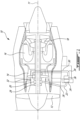
- Fig. 1 illustrates a gas turbine engine 10 of a type preferably provided for use in subsonic flight, generally comprising in serial flow communication a fan 12 through which ambient air is propelled, a compressor section 14 for pressurizing the air, a combustor 16 in which the compressed air is mixed with fuel and ignited for generating an annular stream of hot combustion gases around the engine axis 11, and a turbine section 18 for extracting energy from the combustion gases.
- a gas turbine engine 10 of a type preferably provided for use in subsonic flight, generally comprising in serial flow communication a fan 12 through which ambient air is propelled, a compressor section 14 for pressurizing the air, a combustor 16 in which the compressed air is mixed with fuel and ignited for generating an annular stream of hot combustion gases around the engine axis 11, and a turbine section 18 for extracting energy from the combustion gases.
- the compressor 14, fan 12 and turbine 18 have rotating components which can be mounted on one or more shafts.
- Bearings 20 are used to provide smooth relative rotation between a shaft and casing (non-rotating component), and/or between two shafts which rotate at different speeds.
- An oil lubrication system 22 including an oil pump 24, sometimes referred to as a main pump, and a network of conduits and nozzles 26, is provided to feed the bearings 20 with oil.
- Seals 28 are used to contain the oil.
- a scavenge system 30 having cavities 32, conduits 34, and one or more scavenge pumps 36, is used to recover the oil, which can be in the form of an oil foam at that stage, from the bearings 20.
- the oil pump 24 typically draws the oil from an oil reservoir 38, and it is relatively common to use some form of air/oil separating device in the return line. Seals may also be used for various uses and in other types of gas turbine engines, such as on a propeller shaft or a power shaft of a propeller airplane or helicopter to name some potential examples.
- Fig. 2 presents an example of a seal assembly 28.
- the seal assembly 28 is a brush seal.
- the seal assembly 28 generally has an annular geometry defined around an axis which will be referred to as the seal axis 40.
- the seal axis 40 can coincide with a main axis 11 of a gas turbine engine 10 for instance.
- the seal 28 has a support ring 42 which extends annularly around the seal axis 40.
- the seal 28 has a plurality of bristles of a metal material. The bristles each have two opposite ends which will be referred to as the first ends and the second ends. The first ends are secured to the support ring 42, whereas the second ends are free.
- a circular opening 44 concentric to the seal axis 40 is delimited by the second ends of the bristles.
- the bristles extend radially inwardly from the first ends, and support ring 42, to the second ends.
- the bristles extend obliquely, i.e. not only radially but also tangentially, and the second ends can thus be circumferentially offset from corresponding ones of the first ends.
- the bristles may extend purely radially, in which case the second ends will not be offset from the first ends.
- the first ends can be held by the support ring 42 in any suitable way.
- a typical way of holding the first ends at the support ring is by welding the first ends between two annular rails, which can leave a radially-external welding seam 50, with bristles trapped between a front wall 46 axially opposite a rear wall 48, as best seen in Fig. 3 .
- Fig. 3 shows a portion of a cross-sectional view, enlarged, showing a relationship between the seal assembly 28 and a rotor 52 during use.
- the rotor 52 can be engaged in the circular opening 44.
- the seal assembly 28 can be assembled to a stator or another rotor via the support ring 42, and the bristles can extend towards, and engage an external surface of, the rotor 52.
- the second ends of the bristles may remain in contact with the external surface of the rotor 52 during use, when there is relative rotary movement, around the seal axis 40, between the rotor 52 and the support ring 42.
- the tangential portion of the oblique orientation of the bristles can be selected in a manner to be in the same direction as the direction of rotation of the rotor, in a manner that the second ends of the bristles may trail along the external surface of the rotor 52, with the rotor gently pulling the bristles along their length, rather than engage the rotor 52 in a way which would tend to compress or bend the bristles.
- the relative direction of rotation of the rotor 52 may be as shown with the arrow in Fig. 2 , when the seal assembly does not rotate.
- the first example process can include, in sequence, the following steps.
- an elongated strand of wire is produced.
- This elongated strand is cut into a plurality of shorter strands all having a characteristic length.
- the characteristic length can depend on the diameter of the seal for instance (which can depend on a diameter of the rotor 52), or on other parameters associated to the seal's design.
- the shorter strands are assembled into groups of parallel strands referred to herein as tufts.
- the tufts can then be stabilized by gluing or welding at one end, corresponding to a first end of the strands composing it, and the other end can remain free.
- the tufts may then be laid into a fixture and arranged in a desired configuration. At this point, the first ends of the tufts may be cut in order to more closely match the desired configuration.
- the tufts may then be secured to a support ring, which may be performed by gluing or welding for instance. At this point, the tufts may occupy their definite position in the assembly.
- the free ends, opposite the frame, may then be cut into the final shape.
- the bristles may be made of a metal material which can be relative expensive.
- the bristles may be made of an alloy containing nickel, such as cobalt/nickel alloys such as Haynes 25, or nickel chromium alloys such as Hastelloy X, Hastelloy C-276 or Inconel 600, or perhaps stainless steel, which may be relatively expensive materials.
- the cutting of material at one or both ends may represent a source of waste associated to the cost that went into manufacturing the raw materials which are lost/ not ultimately used in the seal assembly.
- assembling the tufts, or arranging the tufts into the desired configuration may be time consuming and a source of manufacturing variations which may represent another source of costs and be associated to a loss of or variability in quality.
- there can be low raw material utilization such as less than 30% of the wire length being present in the final part.
- the manual operations may require highly qualified work force and extended manual operations with a relatively low yield rate due to the manual operations inconsistencies.
- FIG. 4 presents a cross-sectional view taken in a radial plane relative the seal axis 140, where the seal assembly 128 may otherwise have an annular geometry similar to the embodiment shown in Fig. 2 .
- the seal assembly 128 has a support ring 142 extending annularly around the seal axis 140, and a seal 154 extending annularly around the seal axis 140, the seal 154 assembled to the support ring 142.
- the seal 154 has a succession of lobes 159 circumferentially distributed around the seal axis.
- the succession of lobes are made of one or more strips 161 of a flat metal material.
- the succession of lobes can have a plurality of segments 156 extending between a number of alternating folds 158, 160, and is overall arranged in an annular configuration.
- the one or more strips 161 of the flat metal material can be elongated and flat.
- the one or more strips 161 can have two opposite faces, each facing a corresponding side of the strip.
- the one or more strips 161 can be folded regularly but alternatingly onto the first face, forming the first folds, or external folds 158, then onto the second face, forming the second folds, or internal folds 160, back onto the first face, then onto the second face, and so forth.
- a length of the one or more strips 161 can extend from one segment 156 to an adjacent segment 156 across a fold 160, 158.
- the external folds 158 can have an external fold bending radius defined around an external fold bending axis 163 which extends parallel to the seal axis 140.
- the internal folds 160 can have an internal fold bending radius defined around an internal fold bending axis 165 which also extends parallel to the seal axis 140.
- a single strip 161 may be folded on alternating sides and extend around the entire circumference of the seal 154 and have a single discontinuity where two opposite ends of the single strip 161 meet.
- a plurality of strips 161 may be joined in an end to end configuration (lengthwisely) and the succession of lobes 159 may have a corresponding plurality of discontinuities where longitudinal ends of adjacent ones of the plurality of strips 161 meet.
- rotation of a rotor engaging the internal folds during use may break the internal folds and form a plurality of discontinuities at the radially inner ends of the segments 156 where the internal folds formerly were.
- the latter process may separate a formerly single strip into a plurality of strips where each one of the strips is associated to a corresponding lobe.
- the succession of lobes 159 can be arranged generally in an annular shape as shown, with a width of the one or more strips 161 extending parallel to the seal axis 140.
- the external folds 158 may be circumferentially adjacent one another in the annular shape, and the internal folds 160 may also be circumferentially adjacent one another in the annular shape.
- the first folds may be at a radially-external region of the annular shape and the second folds may be at a radially-internal region of the annular shape.
- Straight segments 156 of the seal 154 can connect respective ones of the first folds to respective ones of the second folds.
- the segments 156 can be straight and extend obliquely, both radially and tangentially, relative the axis of the annular shape (e.g. at an angle ⁇ relative to the radial orientation).
- a support ring 142 may receive the external folds 158 and extend concentrically around the seal 154.
- the seal 154 is continuous around the entirety of the circumference of the annular shape, and two free ends of the strip 161 may meet adjacent one another at the support ring 142. In another embodiment, it may alternately be preferred to include more than one strip 161 to form the entire circumference.
- the segments 156 of each pair of segments extending from a same external fold 158 are non-parallel, and slightly inclined towards one another, with a spacing distance between the segments 156 of each pair of segments reducing along a length of the segments 156, in a direction radially inward from the external fold 158.
- the bending radius of the internal folds 160 is significantly smaller than the bending radius of the external folds 158.
- the internal folds 160 connect adjacent ones of the straight segments 156.
- An embodiment of a seal assembly 128 such as shown in Fig. 4 may be produced with a process which will be explained in relation with the examples shown in Figs. 5 , 6A and 6B .
- the process may involve the following steps. First, a strip of flat metal material is formed in a width spanning the expected seal thickness. Then, the strip is folded and packed into an annular configuration, such as in a pack ready to weld. The pack may then be installed between a back plate and a front plate, centered, and assembled by welding. After welding, the seal assembly may go through a series of mechanical and thermal treatment operations, while being closer to a functional inner diameter than in the first example presented above. Accordingly, in one embodiment, trimming of the bristles may be avoided.
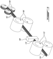
- the strip 161 is formed by arranging a plurality of wires 162 side by side in a single layer, over a given strip width.
- a holding media such as wax may be injected onto the wires to maintain the wires in the strip configuration.
- the wires 162 are individually unwound from corresponding spools 164, and the spools 164 are arranged in alternating orientations, above and below the strip mid line, such that the remanent wire deformation of each wire cancels.
- the wires 162 can be arranged side-by-side to cover the specified width of the strip 161.
- the number of wires 162 in the width can be of between 8 and 20, such as between 12 and 14 for example.
- the wires 162 are pressed by opposed straightening rollers 166 (or more if desired) upstream of the wax injection nozzle 168.
- a composite strip of wires 170 distributed in the wax can be extruded from the hot wax injection nozzle 168.
- the resulting strip 161 may be referred to as being of a flat metal material independently of the presence of the wax or other holding media.
- the strip 161 can then be pressed by opposed laminating rollers 172 to set the dimension.
- the strip 161 may consist of a single flat, continuous strip of metal, e.g. a metal band, rather than of an assembly of wires 162.
- the strip 161 can be engaged into an automated folder or packaging machine.
- two rollers 172, 174 drive the strip 161.
- the strip 161 can be bias-bent to one side of the folder and follow one of the rollers 172.
- the strip 161 goes first to the left, until it meets the corresponding "hammer" 176 (or mould) which can be triggered by the mechanical action of the strip 161 and apply a rapid impact on the strip 161 thus both forming a precise bending radius and pushing the fold on the stack, thus liberating the hammer for the next cycle.
- the impact on the strip 161 may generate a wave in the strip 161 which may propagate and be fed by the incoming strip 161 to form the next fold on the right hand side.
- the right side hammer 178 may operate in a similar manner to left one.
- the right side hammer 178 has a larger bending radius, and two "catching" grooves which are staggered by a depth ⁇ which plays a role in arranging the strip into an annular configuration such as an annular configuration where the straight segments 156 extend obliquely as exemplified above.
- the process may continue to alternate between the left side hammer 176 and the right side hammer 178 which may move laterally to accommodate the functionality.
- the folded strip is received by a curved magazine 180 provided with a receiver plate 182 which can be spring loaded or motioned by an actuator for instance.
- the folded strip package can be transferred from the magazine 180 to a holding device, where it can be welded to a holding element forming the support ring 142.
- the holding element can include two annular rails to which the folded strip package, and more specifically the folds, can be welded, which can leave a radially-external welding seam 50, as best seen in Fig. 3 , and the folds trapped between a front wall 46 and a rear wall 48.
- the strip 161 is formed of a plurality of wires held by a holding media such as wax
- the holding media may be selected in a manner to melt away during welding, or a holding media removal operation may be used (e.g.
- 3300 double folds may be integrated to the manufacturing process, and a packaging machine may form 10 to 20 folds per seconds, producing one pack every 5 minutes or so.
- the resulting bristle pack can have a particular geometry.
- the folding radius of the inner folds 160 may be close to zero, with the strip being bent far into the plastic domain.
- the folding radius of the outer folds 158 may be sufficiently large to account for the increased circumference, such as of the order of 1/3 of the wire diameter.
- the staggering between two consecutive large radius folding can be in the order of the wire diameter, and can be used to accommodate a desired angle ⁇ .
- the finished seal assembly 128 may expose internal folds 160 on the inner functional diameter.
- the internal folds, forming internal tips may wear fast at a first contact with the rotor, and free two loose ends to operate as a typical brush seal or, if the strip is made of a single band of metal rather than a plurality of wires, as a leaf seal.
- the pattern can be made very regular, which may combine better sealing performance with reduced wear.
- the repeatability of the bristle pack geometry may improve performance of a double brush seal by allowing uniform pressure load distribution between the two bristle packs.
- the proposed method may offer repeatability, elimination of manual operation requiring qualified work, more raw material utilization, and uniform micro and macro geometry around the seal circumference.
- a process 200 of making a seal assembly can include folding 210 a strip of metal material into an alternating sequence of internal folds and external folds, and securing 220 the strip of metal material to a support ring having an annular shape defined around a seal axis, including securing the external folds to the support ring in a manner for the strip to be arranged circumferentially relative the axis with the internal folds located radially inwardly relative corresponding ones of the external folds.
Landscapes
- Engineering & Computer Science (AREA)
- General Engineering & Computer Science (AREA)
- Mechanical Engineering (AREA)
- Chemical & Material Sciences (AREA)
- Combustion & Propulsion (AREA)
- Manufacturing & Machinery (AREA)
- Sealing Devices (AREA)
- Turbine Rotor Nozzle Sealing (AREA)
- Gasket Seals (AREA)
Abstract
Description
- The application relates generally to seals and, more particularly, to seals suitable for use in gas turbine engines.
- Seals are used in many turbine applications to impede axial fluid leakage between a stator and a rotor, or between concentric rotors for instance. Several types of seals exist such as carbon seals, labyrinth seals, and brush seals. Brush seals may provide significant benefits to modern gas turbine engines, such as high temperature working environment, low leakage rate, limited axial length and good durability. However, brush seals can be more expensive than some other types of seals. There thus remained room for improvement such as in terms of reducing the costs of brush seals.
- In one aspect, there is provided a seal assembly comprising: a support ring extending annularly around a seal axis; and a seal extending annularly around the seal axis, the seal having a succession of lobes of a flat metal material circumferentially distributed around the seal axis, each lobe of the succession of lobes having a pair of segments extending radially inwardly from a fold, relative the seal axis, the fold secured at the support ring, the fold having a bending radius defined around a bending axis, the bending axis oriented parallel to the seal axis.
- In another aspect, there is provided a process of making a seal assembly, the process comprising: folding a strip of metal material into an alternating sequence of internal folds and external folds; and securing the strip of metal material to a support ring having an annular shape defined around a seal axis, including securing the external folds to the support ring in a manner for the strip to be arranged circumferentially relative the axis with the internal folds located radially inwardly relative corresponding ones of the external folds.
- In a further aspect, there is provided a seal comprising: a strip of metal material, the strip being elongated and flat, the strip having a first face opposite a second face, the strip being regularly folded, alternatingly onto the first face and onto the second face, forming a plurality of first folds and a plurality of second folds, respectively, the strip being arranged in an annular shape around an axis, with the first folds adjacent one another at a radially-external region of the annular shape, the second folds adjacent one another at a radially-internal region of the annular shape and a plurality of straight segments connecting corresponding ones of the first folds to corresponding ones of the second folds; and a support ring having an annular shape defined around the axis, the support ring receiving the first folds.
- Reference is now made to the accompanying figures in which:
-
Fig. 1 is a schematic cross-sectional view of a gas turbine engine; -
Fig. 2 is an oblique view showing an example of a brush seal; -
Fig. 3 is a cross-sectional view taken in an axial plane, showing an example of a brush seal engaged with a rotor; -
Fig. 4 is a cross-sectional view taken in a radial plane, showing a seal made of a flat metal material folded and arranged into a succession of lobes circumferentially distributed around a seal axis; -
Fig. 5 is an oblique view of a process of forming a strip of metal material from a plurality of wires; -
Fig. 6A and 6B are cross sectional views taken at two steps of a sequence of folding a strip of metal material and arranging it circumferentially; -
Fig. 7 is a flowchart of a process of making a seal assembly in accordance with one embodiment. -
Fig. 1 illustrates agas turbine engine 10 of a type preferably provided for use in subsonic flight, generally comprising in serial flow communication afan 12 through which ambient air is propelled, acompressor section 14 for pressurizing the air, acombustor 16 in which the compressed air is mixed with fuel and ignited for generating an annular stream of hot combustion gases around theengine axis 11, and aturbine section 18 for extracting energy from the combustion gases. - The
compressor 14,fan 12 andturbine 18 have rotating components which can be mounted on one or more shafts.Bearings 20 are used to provide smooth relative rotation between a shaft and casing (non-rotating component), and/or between two shafts which rotate at different speeds. Anoil lubrication system 22 including anoil pump 24, sometimes referred to as a main pump, and a network of conduits andnozzles 26, is provided to feed thebearings 20 with oil.Seals 28 are used to contain the oil. Ascavenge system 30 havingcavities 32,conduits 34, and one ormore scavenge pumps 36, is used to recover the oil, which can be in the form of an oil foam at that stage, from thebearings 20. Theoil pump 24 typically draws the oil from an oil reservoir 38, and it is relatively common to use some form of air/oil separating device in the return line. Seals may also be used for various uses and in other types of gas turbine engines, such as on a propeller shaft or a power shaft of a propeller airplane or helicopter to name some potential examples. -
Fig. 2 presents an example of aseal assembly 28. In this example, theseal assembly 28 is a brush seal. Theseal assembly 28 generally has an annular geometry defined around an axis which will be referred to as theseal axis 40. Theseal axis 40 can coincide with amain axis 11 of agas turbine engine 10 for instance. Theseal 28 has asupport ring 42 which extends annularly around theseal axis 40. Theseal 28 has a plurality of bristles of a metal material. The bristles each have two opposite ends which will be referred to as the first ends and the second ends. The first ends are secured to thesupport ring 42, whereas the second ends are free. Acircular opening 44 concentric to theseal axis 40 is delimited by the second ends of the bristles. The bristles extend radially inwardly from the first ends, and supportring 42, to the second ends. In this embodiment, the bristles extend obliquely, i.e. not only radially but also tangentially, and the second ends can thus be circumferentially offset from corresponding ones of the first ends. Alternately, the bristles may extend purely radially, in which case the second ends will not be offset from the first ends. The first ends can be held by thesupport ring 42 in any suitable way. A typical way of holding the first ends at the support ring is by welding the first ends between two annular rails, which can leave a radially-external welding seam 50, with bristles trapped between a front wall 46 axially opposite arear wall 48, as best seen inFig. 3 . -
Fig. 3 shows a portion of a cross-sectional view, enlarged, showing a relationship between theseal assembly 28 and arotor 52 during use. Therotor 52 can be engaged in thecircular opening 44. Theseal assembly 28 can be assembled to a stator or another rotor via thesupport ring 42, and the bristles can extend towards, and engage an external surface of, therotor 52. The second ends of the bristles may remain in contact with the external surface of therotor 52 during use, when there is relative rotary movement, around theseal axis 40, between therotor 52 and thesupport ring 42. The tangential portion of the oblique orientation of the bristles can be selected in a manner to be in the same direction as the direction of rotation of the rotor, in a manner that the second ends of the bristles may trail along the external surface of therotor 52, with the rotor gently pulling the bristles along their length, rather than engage therotor 52 in a way which would tend to compress or bend the bristles. In other words, the relative direction of rotation of therotor 52 may be as shown with the arrow inFig. 2 , when the seal assembly does not rotate. - A first example process of manufacturing such a
seal assembly 28 will now be described. The first example process can include, in sequence, the following steps. To begin, an elongated strand of wire is produced. This elongated strand is cut into a plurality of shorter strands all having a characteristic length. The characteristic length can depend on the diameter of the seal for instance (which can depend on a diameter of the rotor 52), or on other parameters associated to the seal's design. The shorter strands are assembled into groups of parallel strands referred to herein as tufts. The tufts can then be stabilized by gluing or welding at one end, corresponding to a first end of the strands composing it, and the other end can remain free. The tufts may then be laid into a fixture and arranged in a desired configuration. At this point, the first ends of the tufts may be cut in order to more closely match the desired configuration. The tufts may then be secured to a support ring, which may be performed by gluing or welding for instance. At this point, the tufts may occupy their definite position in the assembly. The free ends, opposite the frame, may then be cut into the final shape. - While the first example process may be satisfactory in some embodiments, it may be deemed to bear inconveniences in other embodiments. In particular, such a first example process may have several sources of costs. First, the bristles may be made of a metal material which can be relative expensive. For instance, the bristles may be made of an alloy containing nickel, such as cobalt/nickel alloys such as Haynes 25, or nickel chromium alloys such as Hastelloy X, Hastelloy C-276 or Inconel 600, or perhaps stainless steel, which may be relatively expensive materials. In this context, the cutting of material at one or both ends may represent a source of waste associated to the cost that went into manufacturing the raw materials which are lost/ not ultimately used in the seal assembly. Moreover, assembling the tufts, or arranging the tufts into the desired configuration, may be time consuming and a source of manufacturing variations which may represent another source of costs and be associated to a loss of or variability in quality. In some cases, there can be low raw material utilization, such as less than 30% of the wire length being present in the final part. The manual operations may require highly qualified work force and extended manual operations with a relatively low yield rate due to the manual operations inconsistencies.
- Another embodiment of a
seal assembly 128 will be presented in relation withFig. 4 . More specifically,Fig. 4 presents a cross-sectional view taken in a radial plane relative theseal axis 140, where theseal assembly 128 may otherwise have an annular geometry similar to the embodiment shown inFig. 2 . More specifically, theseal assembly 128 has asupport ring 142 extending annularly around theseal axis 140, and aseal 154 extending annularly around theseal axis 140, theseal 154 assembled to thesupport ring 142. In this embodiment, however, rather than having a seal consisting of a plurality of distinct bristles assembled to the support ring, theseal 154 has a succession of lobes 159 circumferentially distributed around the seal axis. - The succession of lobes are made of one or more strips 161 of a flat metal material. The succession of lobes can have a plurality of
segments 156 extending between a number of alternatingfolds external folds 158, then onto the second face, forming the second folds, orinternal folds 160, back onto the first face, then onto the second face, and so forth. A length of the one or more strips 161 can extend from onesegment 156 to anadjacent segment 156 across afold external folds 158 can have an external fold bending radius defined around an external fold bending axis 163 which extends parallel to theseal axis 140. Theinternal folds 160 can have an internal fold bending radius defined around an internal fold bending axis 165 which also extends parallel to theseal axis 140. In one embodiment, a single strip 161 may be folded on alternating sides and extend around the entire circumference of theseal 154 and have a single discontinuity where two opposite ends of the single strip 161 meet. In another embodiment, a plurality of strips 161 may be joined in an end to end configuration (lengthwisely) and the succession of lobes 159 may have a corresponding plurality of discontinuities where longitudinal ends of adjacent ones of the plurality of strips 161 meet. During operation, rotation of a rotor engaging the internal folds during use may break the internal folds and form a plurality of discontinuities at the radially inner ends of thesegments 156 where the internal folds formerly were. In one embodiment, the latter process may separate a formerly single strip into a plurality of strips where each one of the strips is associated to a corresponding lobe. - The succession of lobes 159 can be arranged generally in an annular shape as shown, with a width of the one or more strips 161 extending parallel to the
seal axis 140. Theexternal folds 158 may be circumferentially adjacent one another in the annular shape, and theinternal folds 160 may also be circumferentially adjacent one another in the annular shape. The first folds may be at a radially-external region of the annular shape and the second folds may be at a radially-internal region of the annular shape.Straight segments 156 of theseal 154 can connect respective ones of the first folds to respective ones of the second folds. In the illustrated embodiments, thesegments 156 can be straight and extend obliquely, both radially and tangentially, relative the axis of the annular shape (e.g. at an angle α relative to the radial orientation). Asupport ring 142 may receive theexternal folds 158 and extend concentrically around theseal 154. In one embodiment, theseal 154 is continuous around the entirety of the circumference of the annular shape, and two free ends of the strip 161 may meet adjacent one another at thesupport ring 142. In another embodiment, it may alternately be preferred to include more than one strip 161 to form the entire circumference. - As can be seen in the example presented in
Fig. 4 , thesegments 156 of each pair of segments extending from a sameexternal fold 158 are non-parallel, and slightly inclined towards one another, with a spacing distance between thesegments 156 of each pair of segments reducing along a length of thesegments 156, in a direction radially inward from theexternal fold 158. Indeed, the bending radius of theinternal folds 160 is significantly smaller than the bending radius of the external folds 158. Theinternal folds 160 connect adjacent ones of thestraight segments 156. - An embodiment of a
seal assembly 128 such as shown inFig. 4 may be produced with a process which will be explained in relation with the examples shown inFigs. 5 ,6A and 6B . Generally, the process may involve the following steps. First, a strip of flat metal material is formed in a width spanning the expected seal thickness. Then, the strip is folded and packed into an annular configuration, such as in a pack ready to weld. The pack may then be installed between a back plate and a front plate, centered, and assembled by welding. After welding, the seal assembly may go through a series of mechanical and thermal treatment operations, while being closer to a functional inner diameter than in the first example presented above. Accordingly, in one embodiment, trimming of the bristles may be avoided. - In the example embodiment presented in
Fig. 5 , the strip 161 is formed by arranging a plurality ofwires 162 side by side in a single layer, over a given strip width. A holding media such as wax may be injected onto the wires to maintain the wires in the strip configuration. In the illustrated embodiment, thewires 162 are individually unwound from correspondingspools 164, and thespools 164 are arranged in alternating orientations, above and below the strip mid line, such that the remanent wire deformation of each wire cancels. Thewires 162 can be arranged side-by-side to cover the specified width of the strip 161. The number ofwires 162 in the width can be of between 8 and 20, such as between 12 and 14 for example. Thewires 162 are pressed by opposed straightening rollers 166 (or more if desired) upstream of thewax injection nozzle 168. A composite strip ofwires 170 distributed in the wax can be extruded from the hotwax injection nozzle 168. The resulting strip 161 may be referred to as being of a flat metal material independently of the presence of the wax or other holding media. The strip 161 can then be pressed by opposed laminatingrollers 172 to set the dimension. In an alternate embodiment, the strip 161 may consist of a single flat, continuous strip of metal, e.g. a metal band, rather than of an assembly ofwires 162. - Referring now to
Figs. 6A and 6B , the strip 161 can be engaged into an automated folder or packaging machine. In this example, tworollers rollers 172. In this example, the strip 161 goes first to the left, until it meets the corresponding "hammer" 176 (or mould) which can be triggered by the mechanical action of the strip 161 and apply a rapid impact on the strip 161 thus both forming a precise bending radius and pushing the fold on the stack, thus liberating the hammer for the next cycle. The impact on the strip 161 may generate a wave in the strip 161 which may propagate and be fed by the incoming strip 161 to form the next fold on the right hand side. Theright side hammer 178 may operate in a similar manner to left one. In the illustrated embodiment, theright side hammer 178 has a larger bending radius, and two "catching" grooves which are staggered by a depth γ which plays a role in arranging the strip into an annular configuration such as an annular configuration where thestraight segments 156 extend obliquely as exemplified above. The process may continue to alternate between theleft side hammer 176 and theright side hammer 178 which may move laterally to accommodate the functionality. In the illustrated embodiment, the folded strip is received by acurved magazine 180 provided with areceiver plate 182 which can be spring loaded or motioned by an actuator for instance. - Once the folded strip package reaches the desired dimensions, it can be transferred from the
magazine 180 to a holding device, where it can be welded to a holding element forming thesupport ring 142. Referring back toFig. 3 , the holding element can include two annular rails to which the folded strip package, and more specifically the folds, can be welded, which can leave a radially-external welding seam 50, as best seen inFig. 3 , and the folds trapped between a front wall 46 and arear wall 48. In an embodiment where the strip 161 is formed of a plurality of wires held by a holding media such as wax, the holding media may be selected in a manner to melt away during welding, or a holding media removal operation may be used (e.g. solvent, oven heating, etc). In one example embodiment of forming a brush seal having an inner diameter of 7" (~18cm), 3300 double folds may be integrated to the manufacturing process, and a packaging machine may form 10 to 20 folds per seconds, producing one pack every 5 minutes or so. - Referring back to
Fig. 4 , the resulting bristle pack can have a particular geometry. The folding radius of theinner folds 160 may be close to zero, with the strip being bent far into the plastic domain. The folding radius of theouter folds 158 may be sufficiently large to account for the increased circumference, such as of the order of 1/3 of the wire diameter. The staggering between two consecutive large radius folding can be in the order of the wire diameter, and can be used to accommodate a desired angle α. Thefinished seal assembly 128 may exposeinternal folds 160 on the inner functional diameter. In a context where the stiffness may be pronounced due to the presence of the two adjacentstraight segments 156, the internal folds, forming internal tips, may wear fast at a first contact with the rotor, and free two loose ends to operate as a typical brush seal or, if the strip is made of a single band of metal rather than a plurality of wires, as a leaf seal. The pattern can be made very regular, which may combine better sealing performance with reduced wear. The repeatability of the bristle pack geometry may improve performance of a double brush seal by allowing uniform pressure load distribution between the two bristle packs. - Overall, depending on the details of implementation, the proposed method may offer repeatability, elimination of manual operation requiring qualified work, more raw material utilization, and uniform micro and macro geometry around the seal circumference.
- In summary, as presented in
Fig. 7 , aprocess 200 of making a seal assembly can include folding 210 a strip of metal material into an alternating sequence of internal folds and external folds, and securing 220 the strip of metal material to a support ring having an annular shape defined around a seal axis, including securing the external folds to the support ring in a manner for the strip to be arranged circumferentially relative the axis with the internal folds located radially inwardly relative corresponding ones of the external folds. - The embodiments described in this document provide non-limiting examples of possible implementations of the present technology. Upon review of the present disclosure, a person of ordinary skill in the art will recognize that changes may be made to the embodiments described herein without departing from the scope of the present technology. For example, a method similar to the one described in detail above may be used for "leaf" seals. The "leaf" seals are similar to brush seal except that instead of adjacent bristle across the thickness they use rectangular "leaves"-like thin metal sheet strips spanning the seal thickness, laid at an angle corresponding to the rotor direction of rotation and stacked around the circumference. Yet further modifications could be implemented by a person of ordinary skill in the art in view of the present disclosure, which modifications would be within the scope of the present technology.
Claims (15)
- A seal assembly (128) comprising:a support ring (142) extending annularly around a seal axis (140), the support ring (142) having a front wall axially opposed to a rear wall; anda seal (154) extending annularly around the seal axis (140), the seal (154) extending radially inwardly from the support ring (142), the seal (154) having a succession of lobes of a flat metal material circumferentially distributed around the seal axis (140), each lobe of the succession of lobes having a pair of segments (156) extending radially inwardly from a fold (158), relative the seal axis (140), the fold (158) secured at the support ring (142) and axially trapped between the front wall and the rear wall, the fold (158) having a bending radius defined around a bending axis, the bending axis oriented parallel to the seal axis (140).
- The seal assembly (128) of claim 1, wherein the segments of each pair of segments (156) are inclined towards one another, a spacing distance between the segments (156) reducing along a length of the segments (156), in a direction radially inward from the fold (158).
- The seal assembly (128) of claim 1 or 2, wherein the flat metal material has a length extending from one of the segments of the pair of segments (156) to an other one of the segments of the pair of segments (156) via the fold (158), and includes a plurality of wires (162) parallel to one another and oriented along the length, a thickness of the flat metal material corresponding to a diameter of the wires (162), the seal assembly (128) being a brush seal, wherein, optionally, the seal assembly (128) further comprises wax holding the plurality of wires (162) to one another.
- The seal assembly (128) of claim 1, 2 or 3, wherein the segments of each pair of segments (156) extend straight and obliquely, both radially and tangentially relative the seal axis (140).
- The seal assembly (128) of any preceding claim, wherein the folds of the plurality of strips are external folds (158), further comprising a plurality of internal folds (160) connecting segments of adjacent ones of the pairs of segments (156) radially inwardly relative the external folds (158).
- The seal assembly (128) of claim 5, wherein the internal folds (160) have a bending radius smaller than the bending radius of the external folds (158).
- The seal assembly (128) of claim 5 or 6, wherein the lobes of are connected to one another at the internal folds (160), the internal folds (160) alternating with the external folds (158) circumferentially around the seal axis (140).
- The seal assembly (128) of any preceding claim, wherein each segment of the pairs of segments (156) have a portion in contact with an adjacent one of the segments of the pairs of segments (156).
- The seal assembly (128) of any preceding claim, wherein the metal material is an alloy including nickel, and, optionally, the alloy further includes at least one of cobalt and chromium.
- A process (200) of making a seal assembly (128), the process (200) comprising:folding a strip of metal material into an alternating sequence of internal folds (160) and external folds (158); andsecuring the strip of metal material to a support ring (142) having an annular shape defined around a seal axis (140), including securing the external folds (158) to the support ring (142) in a manner for the strip to be arranged circumferentially relative the seal axis (140) with the internal folds (160) located radially inwardly relative the external folds (158).
- The process (200) of claim 10, further comprising:forming the strip of metal material including assembling a plurality of wires (162) adjacent one another into a strip arrangement, and applying a holding media to the strip arrangement to hold the plurality of wires (162) in the strip arrangement; andoptionally, removing the holding media during or subsequently to said securing.
- The process (200) of claim 10 or 11, wherein said securing includes welding the external folds (158) to the support ring (142).
- The process (200) of claim 10, 11 or 12, wherein said folding includes feeding the strip into a spacing defined between an external fold hammer and an internal fold hammer in a manner for the feeding of the strip to alternatingly engage the internal fold hammer and the external fold hammer, the internal fold hammer forming the internal folds (160) and the external fold hammer forming the external folds (158), and, optionally, said folding includes moving the external fold hammer and the internal fold hammer into and away from the spacing while feeding the strip.
- The process (200) of claim 13, wherein said folding includes accumulating a folded portion of the strip in a magazine (180) having a curved shape corresponding to the annular shape of the support ring (142).
- The process (200) of any of claims 10 to 14, further comprising:engaging a rotor within a circular opening concentric to the seal axis (140) and delimited by the internal folds (160); andoptionally, rotating the rotor relative the seal assembly (128), around the seal axis (140), thereby breaking the strip of metal material at the internal folds (160).
Applications Claiming Priority (1)
| Application Number | Priority Date | Filing Date | Title |
|---|---|---|---|
| US18/325,050 US12258866B2 (en) | 2023-05-29 | 2023-05-29 | Seal assembly and method of manufacturing |
Publications (1)
| Publication Number | Publication Date |
|---|---|
| EP4471302A1 true EP4471302A1 (en) | 2024-12-04 |
Family
ID=91331134
Family Applications (1)
| Application Number | Title | Priority Date | Filing Date |
|---|---|---|---|
| EP24178888.4A Pending EP4471302A1 (en) | 2023-05-29 | 2024-05-29 | Seal assembly and method of manufacturing |
Country Status (3)
| Country | Link |
|---|---|
| US (2) | US12258866B2 (en) |
| EP (1) | EP4471302A1 (en) |
| CA (1) | CA3238738A1 (en) |
Citations (3)
| Publication number | Priority date | Publication date | Assignee | Title |
|---|---|---|---|---|
| GB2026627A (en) * | 1978-07-08 | 1980-02-06 | Rolls Royce | Seals |
| US20110156361A1 (en) * | 2009-12-29 | 2011-06-30 | Saint-Gobain Performance Plastics Corporation | Springs and methods of forming same |
| US20110182721A1 (en) * | 2010-01-25 | 2011-07-28 | Rolls-Royce Plc | Sealing arrangement for a gas turbine engine |
Family Cites Families (15)
| Publication number | Priority date | Publication date | Assignee | Title |
|---|---|---|---|---|
| NL139671B (en) * | 1969-04-24 | 1973-09-17 | Coq Nv | METHOD AND BENDING MACHINE FOR THE MANUFACTURE OF A RING-SHAPED FIXED SWITCH CONTACT USING ZIG-ZAG SHAPED FOLDED FLAT CONTACT STRIP AND FIXED SWITCH CONTACT, MANUFACTURED BY THIS METHOD. |
| DE2246392C3 (en) * | 1972-09-21 | 1975-06-19 | Klaus Dipl.-Ing. 8192 Geretsried Keller | Device for bending strut snakes |
| GB8504331D0 (en) * | 1985-02-20 | 1985-03-20 | Rolls Royce | Brush seals |
| US5556172A (en) * | 1994-05-11 | 1996-09-17 | Technetics Corporation | Brush seal bristle cutting method |
| DE19613510C1 (en) * | 1996-04-04 | 1997-04-24 | Mtu Muenchen Gmbh | Brush seal for sealing ring-shaped gap between rotor-stator arrangement |
| DE10006298A1 (en) * | 2000-02-12 | 2001-08-16 | Abb Patent Gmbh | Seal for rotating parts |
| GB2365082B (en) * | 2000-07-18 | 2003-10-08 | Rolls Royce Plc | A method of manufacturing seals |
| US7744093B2 (en) * | 2002-08-23 | 2010-06-29 | Rolls-Royce Plc | Seals and a method of making seals |
| GB0613989D0 (en) | 2006-07-14 | 2006-08-23 | Rolls Royce Plc | leaf Seals |
| US20080224415A1 (en) * | 2007-03-15 | 2008-09-18 | Flaherty Andrew L | Brush Seal Assembly And Method Of Making |
| US20130033008A1 (en) * | 2011-08-03 | 2013-02-07 | General Electric Company | Outward bristle brush seal design for gas turbine application |
| GB201113590D0 (en) * | 2011-08-08 | 2011-09-21 | Rolls Royce Plc | Leaf seal |
| GB201113691D0 (en) | 2011-08-09 | 2011-09-21 | Rolls Royce Plc | Leaf seal |
| WO2013153866A1 (en) * | 2012-04-08 | 2013-10-17 | イーグル工業株式会社 | Brush seal |
| KR102039978B1 (en) * | 2019-06-03 | 2019-11-04 | 백승진 | Iron panel bending device |
-
2023
- 2023-05-29 US US18/325,050 patent/US12258866B2/en active Active
-
2024
- 2024-05-16 CA CA3238738A patent/CA3238738A1/en active Pending
- 2024-05-29 EP EP24178888.4A patent/EP4471302A1/en active Pending
-
2025
- 2025-02-18 US US19/055,858 patent/US20250215804A1/en active Pending
Patent Citations (3)
| Publication number | Priority date | Publication date | Assignee | Title |
|---|---|---|---|---|
| GB2026627A (en) * | 1978-07-08 | 1980-02-06 | Rolls Royce | Seals |
| US20110156361A1 (en) * | 2009-12-29 | 2011-06-30 | Saint-Gobain Performance Plastics Corporation | Springs and methods of forming same |
| US20110182721A1 (en) * | 2010-01-25 | 2011-07-28 | Rolls-Royce Plc | Sealing arrangement for a gas turbine engine |
Also Published As
| Publication number | Publication date |
|---|---|
| CA3238738A1 (en) | 2025-06-11 |
| US12258866B2 (en) | 2025-03-25 |
| US20250215804A1 (en) | 2025-07-03 |
| US20240401492A1 (en) | 2024-12-05 |
Similar Documents
| Publication | Publication Date | Title |
|---|---|---|
| EP3214275B1 (en) | Method of manufacturing two brush seals | |
| EP3196518B1 (en) | Seal shoe for a hydrostatic non-contact seal device | |
| EP3611349B1 (en) | Blade outer air seal made of ceramic matrix composite | |
| EP3039250B1 (en) | Blade outer air seal made of ceramic matrix composite | |
| EP3734021A1 (en) | Blade outer air seal | |
| US10794208B2 (en) | Non-contact seal assembly for rotational equipment with linkage between adjacent rotors | |
| EP3112601B1 (en) | Segmented non-contact seal assembly for rotational equipment | |
| EP3133240A1 (en) | Non-contact seal assembly for rotational equipment | |
| US10208674B2 (en) | Multi-axial brush seal | |
| EP3415798B1 (en) | Hydrostatic non-contact seal with varied thickness beams | |
| CN101144542A (en) | Shaft seal using shingle-type compliant-plate members | |
| EP3447344A1 (en) | Hydrostatic non-contact seal with dual material | |
| US11028712B2 (en) | Seal support feature for brush seals | |
| EP3447343B1 (en) | Brush seal with sliding backing plate | |
| US6553639B2 (en) | Method of manufacturing seals | |
| EP1892381A2 (en) | Sealing arrangement | |
| EP2669554B1 (en) | Seal and method of forming a seal | |
| US12258866B2 (en) | Seal assembly and method of manufacturing | |
| EP2886804A1 (en) | Sealing device for a compressor of a turbomachine | |
| EP2818769A2 (en) | A leaf seal | |
| US11732598B2 (en) | Ceramic matrix composite turbine shroud shaped for minimizing abradable coating layer | |
| EP3767077A1 (en) | Cmc boas arrangement | |
| EP3450698A1 (en) | Brush seal with extended backing plate | |
| GB2502309A (en) | A honeycomb seal a method of manufacturing a honeycomb seal | |
| JP6125773B2 (en) | Leaf seal |
Legal Events
| Date | Code | Title | Description |
|---|---|---|---|
| PUAI | Public reference made under article 153(3) epc to a published international application that has entered the european phase |
Free format text: ORIGINAL CODE: 0009012 |
|
| STAA | Information on the status of an ep patent application or granted ep patent |
Free format text: STATUS: THE APPLICATION HAS BEEN PUBLISHED |
|
| AK | Designated contracting states |
Kind code of ref document: A1 Designated state(s): AL AT BE BG CH CY CZ DE DK EE ES FI FR GB GR HR HU IE IS IT LI LT LU LV MC ME MK MT NL NO PL PT RO RS SE SI SK SM TR |
|
| STAA | Information on the status of an ep patent application or granted ep patent |
Free format text: STATUS: REQUEST FOR EXAMINATION WAS MADE |
|
| 17P | Request for examination filed |
Effective date: 20250604 |
|
| STAA | Information on the status of an ep patent application or granted ep patent |
Free format text: STATUS: EXAMINATION IS IN PROGRESS |
|
| 17Q | First examination report despatched |
Effective date: 20260203 |