EP4471290A1 - Ball screw device and electric actuator provided with same - Google Patents
Ball screw device and electric actuator provided with same Download PDFInfo
- Publication number
- EP4471290A1 EP4471290A1 EP22922226.0A EP22922226A EP4471290A1 EP 4471290 A1 EP4471290 A1 EP 4471290A1 EP 22922226 A EP22922226 A EP 22922226A EP 4471290 A1 EP4471290 A1 EP 4471290A1
- Authority
- EP
- European Patent Office
- Prior art keywords
- nut
- screw shaft
- screw
- ball screw
- balls
- Prior art date
- Legal status (The legal status is an assumption and is not a legal conclusion. Google has not performed a legal analysis and makes no representation as to the accuracy of the status listed.)
- Pending
Links
Images


Classifications
-
- F—MECHANICAL ENGINEERING; LIGHTING; HEATING; WEAPONS; BLASTING
- F16—ENGINEERING ELEMENTS AND UNITS; GENERAL MEASURES FOR PRODUCING AND MAINTAINING EFFECTIVE FUNCTIONING OF MACHINES OR INSTALLATIONS; THERMAL INSULATION IN GENERAL
- F16H—GEARING
- F16H25/00—Gearings comprising primarily only cams, cam-followers and screw-and-nut mechanisms
- F16H25/18—Gearings comprising primarily only cams, cam-followers and screw-and-nut mechanisms for conveying or interconverting oscillating or reciprocating motions
- F16H25/20—Screw mechanisms
- F16H25/24—Elements essential to such mechanisms, e.g. screws, nuts
-
- F—MECHANICAL ENGINEERING; LIGHTING; HEATING; WEAPONS; BLASTING
- F16—ENGINEERING ELEMENTS AND UNITS; GENERAL MEASURES FOR PRODUCING AND MAINTAINING EFFECTIVE FUNCTIONING OF MACHINES OR INSTALLATIONS; THERMAL INSULATION IN GENERAL
- F16H—GEARING
- F16H25/00—Gearings comprising primarily only cams, cam-followers and screw-and-nut mechanisms
- F16H25/18—Gearings comprising primarily only cams, cam-followers and screw-and-nut mechanisms for conveying or interconverting oscillating or reciprocating motions
- F16H25/20—Screw mechanisms
- F16H25/22—Screw mechanisms with balls, rollers, or similar members between the co-operating parts; Elements essential to the use of such members
- F16H25/2204—Screw mechanisms with balls, rollers, or similar members between the co-operating parts; Elements essential to the use of such members with balls
-
- F—MECHANICAL ENGINEERING; LIGHTING; HEATING; WEAPONS; BLASTING
- F16—ENGINEERING ELEMENTS AND UNITS; GENERAL MEASURES FOR PRODUCING AND MAINTAINING EFFECTIVE FUNCTIONING OF MACHINES OR INSTALLATIONS; THERMAL INSULATION IN GENERAL
- F16H—GEARING
- F16H25/00—Gearings comprising primarily only cams, cam-followers and screw-and-nut mechanisms
- F16H25/18—Gearings comprising primarily only cams, cam-followers and screw-and-nut mechanisms for conveying or interconverting oscillating or reciprocating motions
- F16H25/20—Screw mechanisms
- F16H2025/2062—Arrangements for driving the actuator
- F16H2025/2081—Parallel arrangement of drive motor to screw axis
-
- F—MECHANICAL ENGINEERING; LIGHTING; HEATING; WEAPONS; BLASTING
- F16—ENGINEERING ELEMENTS AND UNITS; GENERAL MEASURES FOR PRODUCING AND MAINTAINING EFFECTIVE FUNCTIONING OF MACHINES OR INSTALLATIONS; THERMAL INSULATION IN GENERAL
- F16H—GEARING
- F16H25/00—Gearings comprising primarily only cams, cam-followers and screw-and-nut mechanisms
- F16H25/18—Gearings comprising primarily only cams, cam-followers and screw-and-nut mechanisms for conveying or interconverting oscillating or reciprocating motions
- F16H25/20—Screw mechanisms
- F16H25/24—Elements essential to such mechanisms, e.g. screws, nuts
- F16H2025/2445—Supports or other means for compensating misalignment or offset between screw and nut
Definitions
- the present invention relates to a ball screw device and an electric actuator provided with the ball screw device.
- Patent Literature 1 discloses an electric actuator provided with a ball screw device.
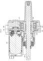
- the electric actuator includes an electric motor 102 and a ball screw device 106.
- the ball screw device 106 includes a nut 121 having a screw groove formed in an inner peripheral surface, a screw shaft 122 having a screw groove formed in an outer peripheral surface, and a large number of balls 123 arranged between the screw groove of the screw shaft 122 and the screw groove of the nut 121.
- the rotational driving force of the motor 102 is decelerated via gears 116 and 117 and transmitted to the nut 121. Then, the rotational motion of the nut 121 is converted into the axial movement of the screw shaft 122 via the balls 123.
- the screw shaft 122 In the ball screw device 106 of the electric actuator illustrated in FIG. 6 , the screw shaft 122, an axially moving body, is supported from the outer periphery by the nut 121 via the balls 123. No other members (bearings or the like) are provided to support the screw shaft 122 from the outer periphery.
- the screw shaft 122 is supported from the outer periphery substantially only at contact portions with the balls 123. In this case, there is no problem when a load in the pure thrust direction is applied to an attachment portion 130 at the end portion of the screw shaft 122 to which another member is to be attached. But, when a load having a radial component is applied, the screw shaft 122 may tilt.
- the screw shaft 122 can be prevented from tilting even when the above-described load is applied.
- a sliding bearing In order to provide such a sliding bearing, however, it is necessary to significantly change the design of the ball screw device.
- the present invention can be applied to, for example, a ball screw device of a nut rotation type in which a nut is caused to function as the rotating body and a screw shaft is caused to function as the axially moving body.
- the transmission gear mechanism 3 includes a small-diameter gear 6 fixed to a rotating shaft 2a of the electric motor 2, and a large-diameter gear 7 meshing with the small-diameter gear 6 and fixed to a nut 8 (details will be described later) of the ball screw device 4.
- the rotational driving force of the electric motor 2 is decelerated by the transmission gear mechanism 3 and transmitted to the nut 8 of the ball screw device 4.
- the transmission gear mechanism 3 is not limited to the above, and may be one that includes, for example, a gear having the same diameter and transmits the rotational driving force of the electric motor 2 to the nut 8 without decelerating the rotational driving force.
- the ball screw device 4 includes the nut 8, a screw shaft 9, and a large number of balls 10.
- Spiral screw grooves 8a and 9a are formed in the inner peripheral surface of the nut 8 and the inner peripheral surface of the screw shaft 9, respectively, and the balls 10 are arranged between the screw grooves 8a and 9a.
- a plurality of (three rows in the illustrated example) circulation paths for circulating the balls 10 are provided as illustrated in FIG. 2 .
- Each circulation path includes a rolling path formed by the screw groove 8a of the nut 8 and the screw groove 9a of the screw shaft 9, and a return path (not illustrated) for returning the ball 10 from the end point to the start point of the rolling path.
- each circulation path has the rolling path for one turn (360°).
- the screw grooves 8a and 9a are provided between the axial directions of the circulation paths adjacent to each other.
- the return path is formed of a known circulating member such as a tube or a circulating piece.
- the contact angle ⁇ is an angle with respect to the radial direction of a line connecting the contact points between the ball 10 and the screw grooves 8a and 9a, and is set to 30° to 45° in an initial state in which the nut 8 and the screw shaft 9 are coaxially arranged.
- the large-diameter gear 7 is fixed to the nut 8, and these are designed to be integrally rotatable.
- the large-diameter gear 7 is arranged between the axial directions of the bearings 11 and 12.
- an annular protrusion 8b is provided on the outer peripheral surface of the nut 8, and the first case 5a and the second case 5b apply a preload in the axial direction to the outer rings of the bearings 11 and 12.
- the large-diameter gear 7 and the annular protrusion 8b are sandwiched between the inner rings of the bearings 11 and 12 from both sides in the axial direction.
- the nut 8 and the large-diameter gear 7 may be integrally formed.
- a plurality of ball screw devices having different tilt errors ⁇ r/L1 of a screw shaft were prepared.
- the life period until peeling occurs on the surface of a screw groove or a ball
- the results are shown in FIG. 5 .
- the life ratio on the vertical axis is the ratio of the life when the life, with the tilt error ⁇ r/L1 assumed to be 1/1000, is one.
Landscapes
- Engineering & Computer Science (AREA)
- General Engineering & Computer Science (AREA)
- Mechanical Engineering (AREA)
- Transmission Devices (AREA)
Abstract
Description
- The present invention relates to a ball screw device and an electric actuator provided with the ball screw device.
-
Patent Literature 1 below discloses an electric actuator provided with a ball screw device. As illustrated inFIG. 6 , the electric actuator includes anelectric motor 102 and aball screw device 106. Theball screw device 106 includes anut 121 having a screw groove formed in an inner peripheral surface, ascrew shaft 122 having a screw groove formed in an outer peripheral surface, and a large number ofballs 123 arranged between the screw groove of thescrew shaft 122 and the screw groove of thenut 121. The rotational driving force of themotor 102 is decelerated viagears nut 121. Then, the rotational motion of thenut 121 is converted into the axial movement of thescrew shaft 122 via theballs 123. - In the ball screw device as described above, it is common to make the gaps between the screw grooves of the screw shaft and the ball and between the screw grooves of the nut and the ball as small as possible. For example, the paragraph 0007 of the following
Patent Literature 2 describes that the ratio of the radial internal gap (radial gap) of the ball screw device to the ball diameter is set to 1/300 or less to prevent the ball from getting on the shoulder portion of the screw groove. In addition, the paragraph 0004 of the followingPatent Literature 3 describes that it is common to apply an axial preload to the ball screw device in order to reduce the elastic displacement amount with respect to the axial load to increase rigidity. When an axial preload is applied to the ball screw device in this way, the radial gap becomes zero. -
- Patent Literature 1:
JP 2018-74791 A - Patent Literature 2:
JP 2013-113423 A - Patent Literature 3:
JP 2004-197806 A - In the
ball screw device 106 of the electric actuator illustrated inFIG. 6 , thescrew shaft 122, an axially moving body, is supported from the outer periphery by thenut 121 via theballs 123. No other members (bearings or the like) are provided to support thescrew shaft 122 from the outer periphery. Thescrew shaft 122 is supported from the outer periphery substantially only at contact portions with theballs 123. In this case, there is no problem when a load in the pure thrust direction is applied to anattachment portion 130 at the end portion of thescrew shaft 122 to which another member is to be attached. But, when a load having a radial component is applied, thescrew shaft 122 may tilt. For example, if a portion of thescrew shaft 122, axially separated from thenut 121, is supported by a sliding bearing or the like, thescrew shaft 122 can be prevented from tilting even when the above-described load is applied. In order to provide such a sliding bearing, however, it is necessary to significantly change the design of the ball screw device. - According to the verification by the present inventors, it has become clear that, when the radial gap is made small as in the
above Patent Document 2 or the radial gap is made 0 as in theabove Patent Document 3 in a ball screw device in which a load having a radial component is applied to thescrew shaft 122, peeling easily occurs on the surfaces of the screw grooves and the balls, which leads to a shortened life. Such a problem is not limited to a ball screw device of a nut rotation type that converts the rotational motion of the nut into the axial movement of the screw shaft, and may similarly occur in a ball screw device of a screw shaft rotation type that converts the rotational motion of the screw shaft into the axial movement of the nut. - Therefore, an object of the present invention is to prevent the life of a ball screw device from being shortened.
- As a result of intensive studies by the present inventors to achieve the above object, it has become clear that, in a ball screw device in which a load having a radial component is applied to an axially moving body, the life of the ball screw device can be prevented from being shortened by intentionally increasing a radial gap, which has been conventionally considered to be preferably as small as possible, and actively providing a tilt error of the axially moving body.
- The present invention made based on the above knowledge relates to a ball screw device including a screw shaft having a screw groove formed in an outer peripheral surface, a nut having a screw groove formed in an inner peripheral surface, and a large number of balls arranged between the screw groove of the screw shaft and the screw groove of the nut, one of the screw shaft and the nut being caused to function as a rotating body and the other being caused to function as an axially moving body, in which
a tilt error represented by a ratio Δr/L1 of a radial gap Δr, which is a maximum amount of radial movement of the nut with respect to the screw shaft, to an axial span L1 between the large number of balls is larger than 1/2000. - By actively providing the tilt error of the axially moving body in this way, a tilt of the axially moving body is allowed when a load having a radial component is applied to the axially moving body, so that early peeling of the surfaces of the balls and the screw grooves can be prevented by avoiding interference between the balls and the screw grooves.
- When a tilt of the axially moving body is allowed as described above and if a deflection amount e (see
FIG. 4 ) of a point of action of load provided on the axially moving body becomes excessively large, there may be a problem depending on the application. Therefore, when it is assumed that the axial distance between the point of action of load provided on the axially moving body and the axial central portion of the large number of balls is L2, it is preferable to make the tilt error Δr/L1 smaller than 0.5/L2. As a result, the deflection amount e of the point of action of load of the axially moving body can be suppressed to 0.5 mm or less (the tolerance class K of JIS B 0419: 1991). - The present invention can be applied to, for example, a ball screw device of a nut rotation type in which a nut is caused to function as the rotating body and a screw shaft is caused to function as the axially moving body.
- In a case where the axially moving body is not supported from the outer periphery at a portion other than the contact portions with a large number of balls, a load is likely to be applied to the screw grooves and the balls when the axially moving body tilts. Therefore, it is particularly effective to apply the present invention.
- When a load including a radial component is applied to the point of action of load of the axially moving body, the axially moving body tilts and a load is likely to be applied to the screw grooves and the balls. Therefore, it is particularly effective to apply the present invention.
- An electric actuator, including the ball screw device and a motor that drives the rotating body, can be prevented from being shortened in life even when a load including a radial component is applied to the axially moving body.
- According to the present invention, the life of the ball screw device can be prevented from being shortened, even when a load having a radial component is applied to the axially moving body, by actively providing the tilt error of the axially moving body, as described above.
-
-
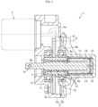
FIG. 1 is a cross-sectional view of an electric actuator. -
FIG. 2 is an enlarged view ofFIG. 1 . -
FIG. 3 is a cross-sectional view illustrating a contact state between a ball and a screw groove. -
FIG. 4 is a cross-sectional view illustrating a state in which a screw shaft tilts with respect to a nut. -
FIG. 5 is a graph illustrating a relationship between a tilt error of a screw shaft and a life ratio of a ball screw device. -
FIG. 6 is a cross-sectional view of a conventional electric actuator. - Hereinafter, an embodiment of the present invention will be described with reference to the drawings.
- An
electric actuator 1 illustrated inFIG. 1 includes anelectric motor 2, atransmission gear mechanism 3, aball screw device 4 according to an embodiment of the present invention, and acase 5. Theelectric actuator 1 is a so-called parallel shaft type electric actuator in which the shaft center of theelectric motor 2 and the shaft center of theball screw device 4 are arranged away from and parallel to each other. In the illustrated example, thecase 5 includes afirst case 5a and asecond case 5b, which are fixed by abolt 5c in a state of being in axial contact with each other. - The
transmission gear mechanism 3 includes a small-diameter gear 6 fixed to a rotatingshaft 2a of theelectric motor 2, and a large-diameter gear 7 meshing with the small-diameter gear 6 and fixed to a nut 8 (details will be described later) of theball screw device 4. As a result, the rotational driving force of theelectric motor 2 is decelerated by thetransmission gear mechanism 3 and transmitted to thenut 8 of theball screw device 4. Note that thetransmission gear mechanism 3 is not limited to the above, and may be one that includes, for example, a gear having the same diameter and transmits the rotational driving force of theelectric motor 2 to thenut 8 without decelerating the rotational driving force. - The
ball screw device 4 includes thenut 8, ascrew shaft 9, and a large number ofballs 10.Spiral screw grooves nut 8 and the inner peripheral surface of thescrew shaft 9, respectively, and theballs 10 are arranged between thescrew grooves balls 10 are provided as illustrated inFIG. 2 . Each circulation path includes a rolling path formed by thescrew groove 8a of thenut 8 and thescrew groove 9a of thescrew shaft 9, and a return path (not illustrated) for returning theball 10 from the end point to the start point of the rolling path. In the illustrated example, each circulation path has the rolling path for one turn (360°). Thescrew grooves ball 10 is arranged, are provided between the axial directions of the circulation paths adjacent to each other. The return path is formed of a known circulating member such as a tube or a circulating piece. When theball screw device 4 is driven, theball 10 and thescrew grooves FIG. 3 . The contact angle α is an angle with respect to the radial direction of a line connecting the contact points between theball 10 and thescrew grooves nut 8 and thescrew shaft 9 are coaxially arranged. - The
nut 8 is attached to thecase 5 viabearings bearing 11 is attached to the inner peripheral surface of thefirst case 5a, and the inner ring is fixed to the outer peripheral surface of thenut 8. The outer ring of theother bearing 12 is attached to the inner peripheral surface of thesecond case 5b, and the inner ring is fixed to the outer peripheral surface of thenut 8. The outer peripheral surfaces of the outer rings of thebearings case 5 are fitted to each other via, for example, a minute radial gap. The inner peripheral surfaces of the inner rings of thebearings nut 8 are fixed by, for example, press fitting. Thenut 8 is rotatably supported with respect to thecase 5 by thesebearings - The large-
diameter gear 7 is fixed to thenut 8, and these are designed to be integrally rotatable. In the illustrated example, the large-diameter gear 7 is arranged between the axial directions of thebearings annular protrusion 8b is provided on the outer peripheral surface of thenut 8, and thefirst case 5a and thesecond case 5b apply a preload in the axial direction to the outer rings of thebearings diameter gear 7 and theannular protrusion 8b are sandwiched between the inner rings of thebearings nut 8 and the large-diameter gear 7 may be integrally formed. - The
screw shaft 9 and thenut 8 are formed of metal, for example, carbon steel, and subjected to heat treatment if necessary. Specifically, thescrew shaft 9 is formed of, for example, a material obtained by subjecting an SUJ material (SUJ2 or the like) or an SC material (S45 C, S53C, or the like) to immersion quenching, or a material obtained by subjecting an SCr material or an SCM material to carburizing and quenching. Thenut 8 is formed of, for example, a material obtained by subjecting an SCr material or an SCM material to carburizing and quenching. - An
attachment hole 9b, as an attachment portion to which another member is to be attached, is provided at one end portion (end portion on the left side in the view) of thescrew shaft 9. Theattachment hole 9b serves as the point of action of a load applied to thescrew shaft 9 from another member. - The
ball screw device 4 is provided with a detent mechanism that restricts the rotation of thescrew shaft 9. In the present embodiment, pins 13 provided on thescrew shaft 9 andaxial grooves 14 provided in thecase 5 constitute the detent mechanism, as illustrated inFIG. 1 . Thepins 13 are provided near the other end portion (end portion on the right side in the view) of thescrew shaft 9, and protrude radially outward from the cylindrical outer peripheral surface of thescrew shaft 9. Theaxial grooves 14 are formed in atubular engagement member 15 fixed to the inner peripheral surface of thesecond case 5b. In the illustrated example, thepins 13 and theaxial grooves 14 are provided at two locations with 180° phase difference, and eachpin 13 is inserted into the inner periphery of eachaxial groove 14. When thescrew shaft 9 tries to turn together with the rotation of thenut 8, thepin 13 and theaxial groove 14 engage in the rotational direction, thereby restricting the rotation of thescrew shaft 9. - The
screw shaft 9 is supported from the outer periphery by thenut 8 via theballs 10. Thescrew shaft 9 is not supported from the outer periphery at a portion other than the contact portions with theballs 10, and is supported from the outer periphery substantially only at contact portions with theballs 10. Note that thepins 13 provided on thescrew shaft 9 are in contact with theaxial grooves 14 of thecase 5 in the rotational direction, but do not support thescrew shaft 9 from the outer periphery. That is, "thescrew shaft 9 is supported from the outer periphery substantially only at contact portions with theballs 10" means a state in which a member that restricts movement in all radial directions like a sliding bearing is not provided in a region of thescrew shaft 9 other than the contact portions with theballs 10. - The distance between the
screw groove 8a of thenut 8 and thescrew groove 9a of thescrew shaft 9 facing each other in the radial direction is slightly larger than the diameter of theball 10. By this amount, thenut 8 is made radially movable with respect to thescrew shaft 9. When it is assumed that the maximum amount of radial movement of thenut 8 with respect to thescrew shaft 9 in a state in which thenut 8 and thescrew shaft 9 are arranged in parallel is a radial gap Δr, it is normal design in the conventional ball screw devices to make the radial gap Δr as small as possible and make the tilt error of the screw shaft as small as possible. On the other hand, in the present invention, the tilt error of the screw shaft is actively provided by setting the radial gap Δr to be large. Specifically, the distance between thescrew grooves ball 10 are set such that a tilt error, represented by a ratio Δr/L1 of the radial gap Δr to an axial span L1 between the large number of balls 10 (the distance between the centers of theballs 10 at the axial both ends. SeeFigure 2 .) is larger than 1/2000, preferably larger than 1/1000, and more preferably larger than 1.5/1000. - By actively providing the tilt error of the
screw shaft 9 as described above, the tilt of thescrew shaft 9 is allowed (the tilt angle is represented by 0) as exaggeratedly illustrated inFIG. 4 . As a result, when a load having a radial component is applied to theattachment hole 9b of thescrew shaft 9, the tilt of thescrew shaft 9 is allowed, so that interference between theball 10 and thescrew grooves ball 10 and thescrew grooves ball screw device 4 can be prevented from being shortened, and eventually the life of theelectric actuator 1 can be prevented from being shortened. - When a tilt error is provided in the
screw shaft 9 as described above, a deflection amount e (seeFIG. 4 ), in the direction orthogonal to the axis, of theattachment hole 9b of thescrew shaft 9 increases. Therefore, when it is assumed that the axial distance between the point of action of load (i.e., the center of theattachment hole 9b) of thescrew shaft 9 and the axial central portion of the large number ofballs 10 is L2 (seeFIG. 2 ), the tilt error Δr/L1 is preferably made smaller than 0.5/L2. As a result, the deflection amount e of theattachment hole 9b of thescrew shaft 9 can be suppressed to 0.5 mm or less. - The
electric actuator 1 is used in an application in which, for example, a wire is attached to theattachment hole 9b of thescrew shaft 9 and the wire is pulled (e.g., an electric parking brake). Alternatively, it is used in an application in which thescrew shaft 9 is in direct or indirect contact with a piston and hydraulic pressure is generated by axial movement of the screw shaft 9 (e.g., an electric hydraulic brake). In particular, when a load having a radial component is applied to theattachment hole 9b of thescrew shaft 9, the electric actuator 1 (ball screw device 4) is suitably applied. - In the above embodiment, the
ball screw device 4 of a nut rotation type that converts the rotation of thenut 8 into the axial movement of thescrew shaft 9 has been described. But, without being limited thereto, the present invention may be applied to a ball screw device of a screw shaft rotation type that converts the rotation of thescrew shaft 9 into the axial movement of thenut 8. Also in this case, it is effective similarly to the above embodiment to apply the present invention when thenut 8, which is an axially moving body, is supported from the outer periphery substantially only at the contact portions with theballs 10. - A plurality of ball screw devices having different tilt errors Δr/L1 of a screw shaft were prepared. The life (period until peeling occurs on the surface of a screw groove or a ball) when the screw shaft was reciprocated in the axial direction with a radial load applied to the tip of the screw shaft was measured. The results are shown in
FIG. 5 . The life ratio on the vertical axis is the ratio of the life when the life, with the tilt error Δr/L1 assumed to be 1/1000, is one. - As illustrated in
FIG. 5 , the life increases as the tilt error Δr/L1 increases from 0, and when the tilt error Δr/L1 is 1/1000 or more, the life ratio is maintained at a high value (near 1). From this result, it was confirmed that by actively providing the tilt error Δr/L1, the life can be made longer than when the tilt error is made small. Specifically, by setting the tilt error Δr/L1 to 0.5/1000 (= 1/2000), a life of about 70% (life ratio of about 0.7) of the maximum life can be obtained. In addition, by setting the tilt error Δr/L1 to 1/1000 or more, and preferably to 1.5/1000 or more, the maximum life (life ratio of about 1) can be obtained. -
- 1
- Electric actuator
- 2
- Electric motor
- 3
- Transmission gear mechanism
- 4
- Ball screw device
- 5
- Case
- 6
- Small-diameter gear
- 7
- Large-diameter gear
- 8
- Nut
- 8a
- Screw groove
- 9
- Screw shaft
- 9a
- Screw groove
- 9b
- Attachment hole (point of action of load)
- 10
- Ball
Claims (6)
- A ball screw device comprising:a screw shaft having a screw groove formed in an outer peripheral surface;a nut having a screw groove formed in an inner peripheral surface; anda large number of balls arranged between the screw groove of the screw shaft and the screw groove of the nut,one of the screw shaft and the nut being caused to function as a rotating body and the other being caused to function as an axially moving body, whereina ratio Δr/L1 of a radial gap Δr, which is a maximum amount of radial movement of the nut with respect to the screw shaft, to an axial span L1 between the large number of balls is larger than 1/2000.
- The ball screw device according to claim 1, whereinwhen it is assumed that an axial distance between a point of action of load provided on the axially moving body and an axial central portion of the large number of balls is L2,the ratio Δr/L1 is smaller than 0.5/L2.
- The ball screw device according to claim 1 or 2, wherein the nut is caused to function as the rotating body, and the screw shaft is caused to function as the axially moving body.
- The ball screw device according to any one of claims 1 to 3, wherein the axially moving body is not supported from an outer periphery at a portion other than contact portions with the large number of balls.
- The ball screw device according to any one of claims 1 to 4, wherein the ball screw device is used in an application in which a load including a radial component is applied to the point of action of load of the axially moving body.
- An electric actuator comprising: the ball screw device according to any one of claims 1 to 5; and a motor that drives the rotating body.
Applications Claiming Priority (2)
| Application Number | Priority Date | Filing Date | Title |
|---|---|---|---|
| JP2022008503A JP2023107346A (en) | 2022-01-24 | 2022-01-24 | Ball screw device and electric actuator provided with the same |
| PCT/JP2022/048355 WO2023140076A1 (en) | 2022-01-24 | 2022-12-27 | Ball screw device and electric actuator provided with same |
Publications (2)
| Publication Number | Publication Date |
|---|---|
| EP4471290A1 true EP4471290A1 (en) | 2024-12-04 |
| EP4471290A4 EP4471290A4 (en) | 2025-05-28 |
Family
ID=87348651
Family Applications (1)
| Application Number | Title | Priority Date | Filing Date |
|---|---|---|---|
| EP22922226.0A Pending EP4471290A4 (en) | 2022-01-24 | 2022-12-27 | Ball screw device and electric actuator equipped therewith |
Country Status (5)
| Country | Link |
|---|---|
| US (1) | US20250092939A1 (en) |
| EP (1) | EP4471290A4 (en) |
| JP (2) | JP2023107346A (en) |
| CN (1) | CN118541554A (en) |
| WO (1) | WO2023140076A1 (en) |
Family Cites Families (5)
| Publication number | Priority date | Publication date | Assignee | Title |
|---|---|---|---|---|
| JP4786835B2 (en) * | 2001-09-05 | 2011-10-05 | 株式会社ジェイテクト | Ball screw device |
| JP2004197806A (en) | 2002-12-17 | 2004-07-15 | Nsk Ltd | Ball screw device |
| JP4610234B2 (en) * | 2004-06-03 | 2011-01-12 | Ntn株式会社 | Ball screw actuator |
| JP2013113423A (en) | 2011-11-30 | 2013-06-10 | Nsk Ltd | Ball screw and injection molding machine |
| JP6333918B2 (en) * | 2016-10-31 | 2018-05-30 | Ntn株式会社 | Electric actuator |
-
2022
- 2022-01-24 JP JP2022008503A patent/JP2023107346A/en active Pending
- 2022-12-27 US US18/728,595 patent/US20250092939A1/en active Pending
- 2022-12-27 EP EP22922226.0A patent/EP4471290A4/en active Pending
- 2022-12-27 CN CN202280088381.6A patent/CN118541554A/en active Pending
- 2022-12-27 WO PCT/JP2022/048355 patent/WO2023140076A1/en not_active Ceased
-
2025
- 2025-09-24 JP JP2025157636A patent/JP2025172237A/en active Pending
Also Published As
| Publication number | Publication date |
|---|---|
| US20250092939A1 (en) | 2025-03-20 |
| JP2023107346A (en) | 2023-08-03 |
| CN118541554A (en) | 2024-08-23 |
| EP4471290A4 (en) | 2025-05-28 |
| JP2025172237A (en) | 2025-11-20 |
| WO2023140076A1 (en) | 2023-07-27 |
Similar Documents
| Publication | Publication Date | Title |
|---|---|---|
| EP1734285B1 (en) | Ball screw | |
| US8141445B2 (en) | Supporting structure of ball screw shaft | |
| EP2667052B1 (en) | Electric linear motion actuator and electric disk brake system | |
| EP2891823B1 (en) | Electric linear motion actuator and electric disk brake system | |
| EP1080318A1 (en) | Screw actuator, and brake calliper comprising such actuator | |
| JPH079260B2 (en) | Combined movement guide device | |
| EP3222881B1 (en) | Electric linear actuator and electric brake device | |
| CN110637178B (en) | Anti-backlash device and method | |
| EP2833022A1 (en) | Ball screw device | |
| US6318516B1 (en) | Bearing arrangement for actuating a brake in a brake system | |
| JP2009036348A (en) | Tandem type double-row angular contact ball bearing and bearing device for pinion shaft | |
| US20250092939A1 (en) | Ball screw device and electric actuator provided with same | |
| JP5138616B2 (en) | Ball screw shaft support structure | |
| JP5082589B2 (en) | Toroidal continuously variable transmission | |
| JP7859283B2 (en) | Ball screw device | |
| JP7768265B2 (en) | Ball screw device | |
| JP2021060104A (en) | Ball screw | |
| JP2017020616A (en) | Four-point ball bearing | |
| US20250257761A1 (en) | Brake assembly with split type race | |
| JP7768264B2 (en) | Ball screw device | |
| JP2025159773A (en) | Actuator | |
| EP1999004B1 (en) | Gear drive system and method | |
| JP5360559B2 (en) | Electric linear actuator and electric brake device | |
| WO2025164593A1 (en) | Ball screw device | |
| JP2024034794A (en) | ball screw device |
Legal Events
| Date | Code | Title | Description |
|---|---|---|---|
| STAA | Information on the status of an ep patent application or granted ep patent |
Free format text: STATUS: THE INTERNATIONAL PUBLICATION HAS BEEN MADE |
|
| PUAI | Public reference made under article 153(3) epc to a published international application that has entered the european phase |
Free format text: ORIGINAL CODE: 0009012 |
|
| STAA | Information on the status of an ep patent application or granted ep patent |
Free format text: STATUS: REQUEST FOR EXAMINATION WAS MADE |
|
| 17P | Request for examination filed |
Effective date: 20240819 |
|
| AK | Designated contracting states |
Kind code of ref document: A1 Designated state(s): AL AT BE BG CH CY CZ DE DK EE ES FI FR GB GR HR HU IE IS IT LI LT LU LV MC ME MK MT NL NO PL PT RO RS SE SI SK SM TR |
|
| DAV | Request for validation of the european patent (deleted) | ||
| DAX | Request for extension of the european patent (deleted) | ||
| A4 | Supplementary search report drawn up and despatched |
Effective date: 20250430 |
|
| RIC1 | Information provided on ipc code assigned before grant |
Ipc: F16H 25/22 20060101ALI20250424BHEP Ipc: F16H 25/24 20060101AFI20250424BHEP |
|
| STAA | Information on the status of an ep patent application or granted ep patent |
Free format text: STATUS: EXAMINATION IS IN PROGRESS |
|
| 17Q | First examination report despatched |
Effective date: 20260122 |