EP4471289A1 - Ball screw device and steering device - Google Patents
Ball screw device and steering device Download PDFInfo
- Publication number
- EP4471289A1 EP4471289A1 EP22921944.9A EP22921944A EP4471289A1 EP 4471289 A1 EP4471289 A1 EP 4471289A1 EP 22921944 A EP22921944 A EP 22921944A EP 4471289 A1 EP4471289 A1 EP 4471289A1
- Authority
- EP
- European Patent Office
- Prior art keywords
- return tube
- ball screw
- return
- leg portion
- length
- Prior art date
- Legal status (The legal status is an assumption and is not a legal conclusion. Google has not performed a legal analysis and makes no representation as to the accuracy of the status listed.)
- Granted
Links
Images



Classifications
-
- F—MECHANICAL ENGINEERING; LIGHTING; HEATING; WEAPONS; BLASTING
- F16—ENGINEERING ELEMENTS AND UNITS; GENERAL MEASURES FOR PRODUCING AND MAINTAINING EFFECTIVE FUNCTIONING OF MACHINES OR INSTALLATIONS; THERMAL INSULATION IN GENERAL
- F16H—GEARING
- F16H25/00—Gearings comprising primarily only cams, cam-followers and screw-and-nut mechanisms
- F16H25/18—Gearings comprising primarily only cams, cam-followers and screw-and-nut mechanisms for conveying or interconverting oscillating or reciprocating motions
- F16H25/20—Screw mechanisms
- F16H25/22—Screw mechanisms with balls, rollers, or similar members between the co-operating parts; Elements essential to the use of such members
- F16H25/2204—Screw mechanisms with balls, rollers, or similar members between the co-operating parts; Elements essential to the use of such members with balls
- F16H25/2214—Screw mechanisms with balls, rollers, or similar members between the co-operating parts; Elements essential to the use of such members with balls with elements for guiding the circulating balls
-
- B—PERFORMING OPERATIONS; TRANSPORTING
- B62—LAND VEHICLES FOR TRAVELLING OTHERWISE THAN ON RAILS
- B62D—MOTOR VEHICLES; TRAILERS
- B62D5/00—Power-assisted or power-driven steering
- B62D5/04—Power-assisted or power-driven steering electrical, e.g. using an electric servo-motor connected to, or forming part of, the steering gear
- B62D5/0442—Conversion of rotational into longitudinal movement
- B62D5/0445—Screw drives
- B62D5/0448—Ball nuts
Definitions
- the present disclosure relates to a ball screw device and a steering system.
- a steering system equipped with an RBS (recirculating ball screw) type gearbox that has a ball screw device, such as described in Patent Document 1, for example.
- a ball screw device includes a screw shaft having a groove on an outer periphery thereof, a ball screw nut having a groove on an inner periphery thereof, a return tube, and a plurality of balls.
- the groove of the screw shaft faces the groove of the ball screw nut to form a rolling path that is helical.
- the return tube has a return path that creates a connection between two points on the rolling path.
- the rolling path and the return path form a circulation path in which the balls are disposed.
- the balls circulate through the circulation path in accordance with operation of the ball screw device.
- Patent Document 1 Japanese Unexamined Patent Application Publication No. 2019-156082 ( JP 2019-156082 A )
- the ball screw device includes a screw shaft having a groove on an outer periphery of the screw shaft, a ball screw nut having a groove on an inner periphery of the ball screw nut, a plurality of return tubes, and a plurality of balls.
- the groove of the screw shaft faces the groove of the ball screw nut to form a helical rolling path.
- Each of the plurality of return tubes includes a return path configured to create a connection between two points of the rolling path, the return path and the rolling path forming a circulation path in which the balls are disposed, a first end portion that serves as an entrance for the balls to enter the return path when the screw shaft or the ball screw nut rotates clockwise, and that serves as an exit for the balls to be discharged from the return path when the screw shaft or the ball screw nut rotates counterclockwise, and a second end portion that serves as an exit for the balls to be discharged from the return path when the screw shaft or the ball screw nut rotates clockwise, and that serves as an entrance for the balls to enter the return path when the screw shaft or the ball screw nut rotates counterclockwise.
- the ball screw nut has a plurality of attaching portions configured such that the plurality of return tubes is attached from a same attaching direction.
- the plurality of return tubes includes at least a first return tube and a second return tube.
- a position of the first end portion of the second return tube relative to a position of the first end portion of the first return tube in a circumferential direction of the ball screw nut is a first relative position
- a position of the second end portion of the second return tube relative to a position of the second end portion of the first return tube in the circumferential direction is a second relative position.
- At least one of the first relative position and the second relative position includes offset in the circumferential direction.
- a steering system in another aspect of the present disclosure, includes the above-described ball screw device, and a steering shaft linked to the screw shaft.
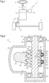
- the steering system 1 illustrated in FIG. 1 steers steered wheels 3 based on operation of a steering wheel 2 by a driver.
- the steering system 1 includes a steering shaft 11, a gearbox 12, a pitman arm 13, and a link mechanism 14.
- One end of the steering shaft 11 is linked to the steering wheel 2, and the other end of the steering shaft 11 is linked to a gearbox 12.
- the gearbox 12 converts rotation of the steering shaft 11 into swinging motion of the pitman arm 13.
- the swinging motion of the pitman arm 13 is transmitted to the steered wheels 3 via the link mechanism 14, thereby steering the steered wheels 3.
- the steering system 1 also includes an electric actuator 15 that generates an assist force to assist steering operations by the driver.
- the electric actuator 15 includes a motor 16 and a speed reducer 17.
- the speed reducer 17 is, for example, a worm and wheel.
- the motor 16 is linked to the steering shaft 11 via the speed reducer 17.
- the electric actuator 15 applies an assist force to the steering shaft 11 by transmitting rotation of the motor 16 to the steering shaft 11 with the speed thereof reduced by the speed reducer 17. That is to say, the steering system 1 according to the present embodiment is an electric power steering system.
- the gearbox 12 is an RBS type gearbox having a ball screw device 21.
- the gearbox 12 includes a housing 22 and a sector shaft 23 having a sector portion 24.
- the housing 22 has, for example, a main unit portion 25 and a bulging portion 26.
- the main unit portion 25 has, for example, a tubular shape with one end thereof closed.
- the bulging portion 26 is provided on a peripheral wall of the main unit portion 25, and an inside of the bulging portion 26 communicates with an inside of the main unit portion 25.
- the bulging portion 26 has, for example, a tubular shape extending in a direction perpendicular to an axial direction of the main unit portion 25.
- the closed side of the housing 22 will be referred to as a lower side
- the open side of the housing 22 will be referred to as an upper side.
- a housing that is omitted from illustration, of the speed reducer 17, is fixed to the upper side of the housing 22.
- tubular as used in the present specification to be an arrangement that can be deemed to be a tubular shape overall, and tubular shapes formed by combining a plurality of components, and shapes formed by partially notching out into a letter-C shaped part or the like, are included therein.
- tubular shape encompasses, circles, ellipses, and polygons with sharp corners or rounded corners, but is not limited thereto.
- the sector shaft 23 is housed in the bulging portion 26.
- the sector shaft 23 is rotatably supported via a bearing that is omitted from illustration.
- the sector shaft 23 has an outer end portion exposed to an outside of the housing 22.
- a basal end portion of the pitman arm 13 is fixed to the outer end portion of the sector shaft 23, so as to be integrally rotatable therewith.
- the sector portion 24 is disposed within the bulging portion 26.
- the sector portion 24 has, for example, a fan-like shape as viewed in the axial direction of the sector shaft 23.
- the sector portion 24 has a plurality of outer teeth 27 provided on an outer peripheral face thereof.
- the ball screw device 21 includes a screw shaft 31 that is linked to the steering shaft 11, a ball screw nut 32 that meshes with the outer teeth 27 of the sector portion 24, and a plurality of balls 33.
- the ball screw device 21 converts rotation of the screw shaft 31 in accordance with rotation of the steering shaft 11 into linear movement of the ball screw nut 32.
- the sector shaft 23 rotates, causing the pitman arm 13 to swing.
- the ball screw device 21 includes a plurality of return tubes, and thus has a plurality of independent circulation paths through which the balls 33 circulate.
- the ball screw device 21 includes a first return tube 34, a second return tube 35, and a holder 36, in addition to the screw shaft 31, the ball screw nut 32, and the plurality of balls 33.
- the ball screw device 21 has two circulation paths, a first circulation path and a second circulation path. Note that the return tubes are sometimes referred to as circulators. Each component of the ball screw device 21 will be described in detail below.
- the screw shaft 31 is rotatably housed within the main unit portion 25.
- the screw shaft 31 is rotatably supported via bearings 41 and 42 provided at an upper side end portion and a lower side end portion of the main unit portion 25, for example.
- the upper side end portion of the screw shaft 31 is linked to the steering shaft 11 so as to be integrally rotatable therewith.
- a groove 43 that is helical is provided on an outer peripheral face of the screw shaft 31.
- the terms “upper side” and “lower side” refer to, for example, the upper side and the lower side respectively, in an up-down direction of the vehicle.
- the ball screw nut 32 has a tubular shape.
- the ball screw nut 32 according to the present embodiment has a square outer peripheral shape and also a circular inner peripheral shape as viewed in the axial direction.
- the ball screw nut 32 has rack teeth 44 on one outer side face thereof.
- the rack teeth 44 mesh with the outer teeth 27 of the sector portion 24.
- the ball screw nut 32 has an inner peripheral face provided with a groove 45 that is helical.
- the groove 43 of the screw shaft 31 faces the groove 45 of the ball screw nut 32 to form a rolling path Rc that is helical.
- the plurality of balls 33 are disposed in the rolling path Rc in a state of being interposed between the grooves 43 and 45. That is to say, the ball screw nut 32 is fitted onto the outer periphery of the screw shaft 31 via the balls 33.
- the ball screw nut 32 has an attaching face 46 to which the first return tube 34 and the second return tube 35 are attached.
- the attaching face 46 is, for example, the outer side face of the ball screw nut 32 that is on the opposite side from the face on which the rack teeth 44 are provided.
- the attaching face 46 has a planar form, for example.
- the first return tube 34 and the second return tube 35 are arranged side by side on the attaching face 46 such that the first return tube 34 is situated above the second return tube 35.
- the attaching face 46 is configured such that the first return tube 34 and the second return tube 35 are attached from the same attaching direction.
- the attaching direction is, for example, a direction perpendicular to the axial direction of the ball screw nut 32, i.e., the direction perpendicular to the attaching face 46.
- the attaching face 46 is provided with a first attaching portion 47 for attaching the first return tube 34 and a second attaching portion 48 for attaching the second return tube 35. Configurations of the first attaching portion 47 and the second attaching portion 48 will be described later.
- the first return tube 34 has a return path R1 that creates a connection between two points of the rolling path Rc.
- the second return tube 35 has a return path R2 that creates a connection between two other points that are different from the above two points on the rolling path Rc.
- a section of the rolling path Rc for which a connection is created by the first return tube 34 does not overlap with a section of the rolling path Rc for which a connection is created by the second return tube 35.
- the return path R1 of the first return tube 34 and the rolling path Rc form a first circulation path
- the return path R2 of the second return tube 35 and the rolling path Rc form a second circulation path.
- the first return tube 34 has a first leg portion 51, a second leg portion 52, and a linking portion 53 that links the first leg portion 51 and the second leg portion 52 to each other. Inner circumferential faces of the first leg portion 51, the second leg portion 52 and the linking portion 53 form the return path R1.
- the first return tube 34 has of shape of a tubular pipe bent into a substantially letter-C shape, for example.
- the first leg portion 51 has a tubular shape that extends linearly along the attaching direction.
- the second leg portion 52 has a tubular shape that extends linearly along the attaching direction. That is to say, the second leg portion 52 extends parallel to the first leg portion 51.
- the linking portion 53 has a tubular shape.
- the linking portion 53 extends, for example, in a direction that is perpendicular to the attaching direction and that also intersects the axial direction of the ball screw nut 32. Also, both end portions of the linking portion 53 are bent so as to be linked to the first leg portion 51 and the second leg portion 52.
- a distal end of the first leg portion 51 is provided with a tongue portion 54 and a fitting portion 55.
- the tongue portion 54 protrudes from an inner side portion of the distal end of the first leg portion 51 in the attaching direction.
- the tongue portion 54 has, for example, a semicircular shape as viewed in a longitudinal direction of the linking portion 53.
- the fitting portion 55 protrudes in the attaching direction from an outer side portion of the distal end of the first leg portion 51.
- the fitting portion 55 has, for example, a semicylindrical shape. The fitting portion 55 protrudes beyond the tongue portion 54.
- the second leg portion 52 has a shape that is symmetrical to the first leg portion 51 with respect to a straight line extending in the attaching direction. That is to say, a distal end of the second leg portion 52 is provided with a tongue portion 56 and a fitting portion 57. Also, a length L11 of the first leg portion 51 along the attaching direction, i.e., a distance from the linking portion 53 to the distal end of the fitting portion 55, is equal to L12 of the second leg portion 52 along the attaching direction, i.e., a distance from the linking portion 53 to a distal end of the fitting portion 57.
- the second return tube 35 has a similar configuration to the first return tube 34, except for dimensions thereof, which will be described below. That is to say, the second return tube 35 has a first leg portion 61, a second leg portion 62, and a linking portion 63 that links the first leg portion 61 and the second leg portion 62 to each other.
- the first leg portion 61 has a tongue portion 64 and a fitting portion 65.
- the second leg portion 62 has a tongue portion 66 and a fitting portion 67.
- the first attaching portion 47 has a first through hole 71 into which the first leg portion 51 of the first return tube 34 is inserted, and a second through hole 72 into which the second leg portion 52 of the first return tube 34 is inserted.
- the second attaching portion 48 has a first through hole 73 into which the first leg portion 61 of the second return tube 35 is inserted, and a second through hole 74 into which the second leg portion 62 of the second return tube 35 is inserted.
- the first through holes 71 and 73, and the second through holes 72 and 74, are all open in a direction opposite to the attaching direction.
- first through holes 71 and 73, and the second through holes 72 and 74 open in the same direction.
- first return tube 34 and the second return tube 35 are attached to the ball screw nut 32 from the same attaching direction, as described above.
- the first through hole 71 and the second through hole 72 of the first attaching portion 47 are provided at positions corresponding to the above two points of the rolling path Rc between which a connection is created by the first return tube 34 as viewed in the attaching direction.
- the first through hole 71 and the second through hole 72 are, for example, circular holes as viewed in the attaching direction.
- a bore diameter of the first through hole 71 is set to be larger than the width of the groove 45 in the axial direction.
- an arc-shaped step is provided between an inner circumferential face of the first through hole 71 and an inner face of the groove 45 as viewed in the attaching direction.
- the first through hole 71 has a bottom face that is arc-shaped as viewed in the attaching direction.
- a depth of the first through hole 71 i.e., a distance between the attaching face 46 and the bottom face (step) of the first through hole 71, is equal to the length L 11 of the first leg portion 51 of the first return tube 34.
- the second through hole 72 has a shape symmetrical to the first through hole 71 with respect to a straight line extending in the attaching direction.
- a depth of the second through hole 72 i.e., a distance between the attaching face 46 and the bottom face (step) of the second through hole 72, is equal to the length L 12 of the second leg portion 52 of the first return tube 34.
- the return path R1 of the first return tube 34 creates a connection between two points on the rolling path Rc, thereby forming the first circulation path.
- the first through hole 73 and the second through hole 74 of the second attaching portion 48 are provided at positions corresponding to the above two other points of the rolling path Rc between which a connection is created by the second return tube 35 as viewed in the attaching direction.
- the first through hole 73 and the second through hole 74 are, for example, circular holes as viewed in the attaching direction.
- a bore diameter of the first through hole 73 is set to be greater than the width of the groove 45 in the axial direction.
- an arc-shaped step is provided between an inner circumferential face of the first through hole 73 and the inner face of the groove 45 as viewed in the attaching direction.
- the first through hole 73 has a bottom face that is arc-shaped as viewed in the attaching direction.
- a depth of the first through hole 73 i.e., a distance between the attaching face 46 and the bottom face (step) of the first through hole 73, is equal to a length L21 of the first leg portion 61 of the second return tube 35.
- the second through hole 74 has a shape symmetrical to the first through hole 73 with respect to a straight line extending in the attaching direction.
- a depth of the second through hole 74 i.e., a distance between the attaching face 46 and a bottom face (step) of the second through hole 74, is equal to a length L22 of the second leg portion 62 of the second return tube 35.
- a straight line linking the center of the first through hole 71 and the center of the second through hole 72 in the first attaching portion 47 is parallel to a straight line linking the center of the first through hole 73 and the center of the second through hole 74 in the second attaching portion 48.
- the linking portion 53 of the first return tube 34 attached to the ball screw nut 32 becomes parallel to the linking portion 63 of the second return tube 35.
- the holder 36 fixes the first return tube 34 and the second return tube 35 to the ball screw nut 32.
- the holder 36 has, for example, an elongated plate shape.
- the holder 36 has a first recessed portion 81 and a second recessed portion 82.
- the linking portion 53 of the first return tube 34 is fit into the first recessed portion 81.
- the linking portion 63 of the second return tube 35 is fit into the second recessed portion 82.
- the holder 36 is fixed to the attaching face 46 of the ball screw nut 32 by bolts 83.
- the holder 36 presses and fixes the first return tube 34 and the second return tube 35 against the attaching face 46 of the ball screw nut 32.
- the balls 33 roll within the rolling path Rc while receiving frictional force from the screw shaft 31 and the ball screw nut 32 in accordance with rotation of the screw shaft 31.
- the balls 33 rolling in the first circulation path roll in the rolling path Rc and reach one of the two points between which a connection is created by the first return tube 34, the balls 33 are discharged to the other by passing through the return path R1.
- the balls 33 move from a downstream side to an upstream side along the rolling path Rc and circulate through the first circulation path.
- the ball 33 is pushed by an adjacent ball 33 located behind in a circulation direction and moves through the return path R1.
- the end portion that serves as an entrance for the balls 33 to enter the return path R1 when the screw shaft 31 rotates clockwise in FIG. 4A and that serves as an exit for the balls 33 to be discharged from the return path R1 when the screw shaft 31 rotates counterclockwise is defined as a first end portion 91.
- the end portion that serves as the exit for the balls 33 to be discharged from the return path R1 when the screw shaft 31 rotates clockwise and that serves as the entrance for the balls 33 to enter the return path R1 when the screw shaft 31 rotates counterclockwise is defined as a second end portion 92.
- the first leg portion 51 When the first leg portion 51 is inserted into the first through hole 71 and also the second leg portion 52 is inserted into the second through hole 72, as in the present embodiment, the first leg portion 51 includes the first end portion 91 and the second leg portion 52 includes the second end portion 92.
- the balls 33 rolling in the second circulation path roll in the rolling path Rc and reach one of the two points between which a connection is created by the second return tube 35, the balls 33 are discharged to the other by passing through the return path R2.
- the balls 33 move from the downstream side to the upstream side along the rolling path Rc and circulate through the second circulation path.
- the section of the rolling path Rc for which a connection is created by the first return tube 34 does not overlap with the section for which a connection is created by the second return tube 35. Accordingly, the balls 33 circulating in the first circulation path do not pass through the second circulation path, but circulate only within the first circulation path. In the same way, the balls 33 circulating in the second circulation path do not pass through the first circulation path, but circulate only within the second circulation path.
- the end portion that serves as the entrance for the balls 33 to enter the return path R2 when the screw shaft 31 rotates clockwise in FIG. 4B and that serves as the exit for the balls 33 to be discharged from the return path R2 when the screw shaft 31 rotates counterclockwise is defined as a first end portion 93.
- the end portion that serves as the exit for the balls 33 to be discharged from the return path R2 when the screw shaft 31 rotates clockwise and that serves as the entrance for the balls 33 to enter the return path R2 when the screw shaft 31 rotates counterclockwise is defined as a second end portion 94.
- the first leg portion 61 When the first leg portion 61 is inserted into the first through hole 73 and also the second leg portion 62 is inserted into the second through hole 74, as in the present embodiment, the first leg portion 61 includes the first end portion 93 and the second leg portion 62 includes the second end portion 94.
- the ball screw device 21 has a plurality of the circulation paths. Accordingly, the length of the rolling path Rc in one circulation path can be prevented from becoming too long, while the length of the rolling path Rc in the entire ball screw device 21 can be increased.
- increasing the number of balls 33 rolling within the rolling path Rc enables a load (i.e., frictional force) applied to each of the plurality of balls 33 from the screw shaft 31 and the ball screw nut 32 to be reduced. Accordingly, the life of the balls 33, and hence the life of the ball screw device 21, can be extended. Furthermore, the length of the rolling path Rc in one circulation path does not become too long, and accordingly contact between balls 33 that are adjacent within the rolling path Rc can be suppressed, for example, allowing the ball screw device 21 to operate smoothly.
- torque required to rotate the screw shaft 31, i.e., steering torque varies depending on the timing at which the balls 33 enter the return tube and the timing at which the balls 33 are discharged from the return tube.
- the timing at which at least a part of a ball 33 is in a state of coming into contact with the return tube is the timing at which the ball 33 enters the return tube
- the timing at which the ball 33 is no longer in a state of being in contact with the return tube is the timing at which the ball 33 is discharged from the return tube.
- a timing at which a ball 33 enters the first return tube 34 and a timing at which a ball 33 enters the second return tube 35 coincide with each other the fluctuation in steering torque will be great. Also, when the timing at which a ball 33 is discharged from the first return tube 34 and the timing at which a ball 33 is discharged from the second return tube 35 coincide with each other, the fluctuation in the steering torque also becomes great.
- the timings of the balls 33 entering and exiting the first return tube 34 and the second return tube 35 are actively offset.
- the position of the first end portion 93 of the second return tube 35 relative to the position of the first end portion 91 of the first return tube 34 in a circumferential direction of the ball screw nut 32 is defined as a first relative position.
- the position of the second end portion 94 of the second return tube 35 relative to the position of the second end portion 92 of the first return tube 34 in the circumferential direction of the ball screw nut 32 is defined as a second relative position.
- both the first relative position and the second relative position include offset in the circumferential direction. This can be understood by overlaying FIG. 4A and FIG.
- the length L11 of the first leg portion 51 and the length L12 of the second leg portion 52 of the first return tube 34 are equal to each other.
- the length L21 of the first leg portion 61 and the length L22 of the second leg portion 62 of the second return tube 35 are equal to each other.
- the length L11 of the first leg portion 51 and the length L12 of the second leg portion 52 of the first return tube 34 are longer than the length L21 of the first leg portion 61 and the length L22 of the second leg portion 62 of the second return tube 35.
- a length L13 of the linking portion 53 of the first return tube 34 and a length L23 of the linking portion 63 of the second return tube 35 are equal with each other.
- both the first relative position and the second relative position include an offset in the circumferential direction of the ball screw nut 32.
- the sum of the amount of circumferential-direction offset of the first relative position and the amount of circumferential-direction offset of the second relative position is different from an integer multiple of the diameter of the ball 33.
- the sum of offset in the present embodiment is, for example, smaller than the diameter of the balls 33, but may be larger than the diameter of the balls 33.
- the ball screw device 21 has the plurality of circulation paths, and accordingly the length of the rolling path Rc in the entire ball screw device 21 can be increased while suppressing the length of the rolling path Rc in one circulation path from becoming too long. Accordingly, reducing the load applied to each of the plurality of balls 33 enables the life of the balls 33, and hence the life of the ball screw device 21, to be extended.
- a ball screw device will be assumed that is configured similarly to the ball screw device 21 except that neither the first relative position nor the second relative position includes offset in the circumferential direction. That is to say, in the comparative example, the position of the first end portion of the first return tube in the circumferential direction of the ball screw nut coincides with the position of the first end portion of the second return tube, and also the position of the second end portion of the first return tube in the circumferential direction of the ball screw nut coincides with the position of the second end portion of the second return tube.
- the timing at which the ball enters the first return tube and the timing at which the ball enters the second return tube, and the timing at which the ball is discharged from the first return tube and the timing at which the ball is discharged from the second return tube readily coincide with each other.
- a rotation angle of the screw shaft 31, i.e., the steering torque varies greatly with respect to the steering angle.
- both the first relative position and the second relative position include offset in the circumferential direction. Accordingly, in at least one of the timing at which the ball 33 enters the first return tube 34 and the timing at which the ball 33 enters the second return tube 35, and the timing at which the ball 33 is discharged from the first return tube 34 and the timing at which the ball 33 is discharged from the second return tube 35, the timings are likely to be offset with each other.
- the timings are likely to be offset with each other.
- the layout of the balls in the return path in the first return tube and the layout of the balls in the return path in the first return tube do not necessarily match each other.
- the balls may be laid out in a zigzag (staggered) pattern in the first return tube and also the balls may be laid out in a straight line in the second return tube.
- the timing at which the balls are discharged from the first return tube may be offset from the timing at which the balls are discharged from the second return tube.
- offset in timing occurs by chance.
- the timing at which the ball enters the first return tube and the timing at which the ball enters the second return tube, and the timing at which the ball is discharged from the first return tube and the timing at which the ball is discharged from the second return tube, readily coincide with each other.
- the steering system 1 includes the ball screw device 21 and the steering shaft 11 linked to the screw shaft 31. According to the above configuration, fluctuations in steering torque are suppressed, and accordingly deterioration of steering feeling can be suppressed.
- the sum of the amount of offset of the first relative position in the circumferential direction and the amount of offset of the second relative position in the circumferential direction is different from an integer multiple of the diameter of the ball 33. Accordingly, in at least one of the timing at which the ball 33 enters the first return tube 34 and the timing at which the ball 33 enters the second return tube 35, and the timing at which the ball 33 is discharged from the first return tube 34 and the timing at which the ball 33 is discharged from the second return tube 35, the timings are suitably readily offset from each other.
- the return tubes 34 and 35 respectively have the first leg portion 51 and 61 having a length along the attaching direction, and the second leg portion 52 and 62 having a length along the attaching direction.
- the length L11 of the first leg portion 51 and the length L12 of the second leg portion 52 of the first return tube 34 are equal to each other.
- the length L21 of the first leg portion 61 and the length L22 of the second leg portion 62 of the second return tube 35 are equal to each other.
- the first leg portion 51 of the first return tube 34 can be inserted into either the first through hole 71 or the second through hole 72, and also the second leg portion 52 can be inserted into either the first through hole 71 or the second through hole 72. Accordingly, when attaching the first return tube 34, it is not necessary to take into consideration the combination of the first leg portion 51 and the first through hole 71, and the combination of the second leg portion 52 and the second through hole 72. This facilitates work of attaching the first return tube 34.
- the first leg portion 61 of the second return tube 35 can be inserted into either the first through hole 73 or the second through hole 74, and also the second leg portion 62 can be inserted into either the first through hole 73 or the second through hole 74. This facilitates work of attaching the second return tube 35.
- the length L11 of the first leg portion 51 of the first return tube 34 is longer than the length L12 of the second leg portion 52 in the present embodiment.
- the length L21 of the first leg portion 61 of the second return tube 35 is shorter than the length L22 of the second leg portion 62.
- the length L11 of the first leg portion 51 of the first return tube 34 and the length L22 of the second leg portion 62 of the second return tube 35 are equal to each other.
- the length L12 of the second leg portion 52 of the first return tube 34 and the length L21 of the first leg portion 61 of the second return tube 35 are equal to each other.
- the length L13 of the linking portion 53 of the first return tube 34 and the length L23 of the linking portion 63 of the second return tube 35 are equal to each other.
- both the first relative position and the second relative position include an offset in the circumferential direction of the ball screw nut 32.
- the sum of the amount of circumferential-direction offset of the first relative position and the amount of circumferential-direction offset of the second relative position is different from an integer multiple of the diameter of the ball 33.
- the sum of offset in the present embodiment is, for example, smaller than the diameter of the balls 33, but may be larger than the diameter of the balls 33.
- the present embodiment described above has the following functions and effects in addition to the functions and effects that are similar to the functions and effects described above in (1-1) to (1-3) according to the first embodiment.
- the return tubes 34, 35 respectively have the first leg portions 51 and 61 having a length along the attaching direction, the second leg portions 52 and 62 having a length along the attaching direction, and the linking portions 53 and 63 that link the first leg portions 51 and 61 and the second leg portions 52 and 62 to each other and have a length along a direction intersecting the attaching direction.
- the length L11 of the first leg portion 51 of the first return tube 34 is different from the length L12 of the second leg portion 52 of the first return tube 34.
- the length L21 of the first leg portion 61 of the second return tube 35 is different from the length L22 of the second leg portion 62 of the second return tube 35.
- the length L11 of the first leg portion 51 of the first return tube 34 and the length L22 of the second leg portion 62 of the second return tube 35 are equal to each other.
- the length L12 of the second leg portion 52 of the first return tube 34 and the length L21 of the first leg portion 61 of the second return tube 35 are equal to each other.
- the length L13 of the linking portion 53 of the first return tube 34 and the length L13 of the linking portion 63 of the second return tube 35 are equal to each other. Accordingly, the first return tube 34 can be formed in the same shape as the second return tube 35.
- the first return tube 34 can be used as the second return tube 35, and also the second return tube 35 can be used as the first return tube 34. This enables reduction in manufacturing costs, for example, as compared to a case in which the shape of the first return tube 34 is different from the shape of the second return tube 35.
- the length L11 of the first leg portion 51 and the length L12 of the second leg portion 52 of the first return tube 34 are equal to each other.
- the length L21 of the first leg portion 61 and the length L22 of the second leg portion 62 of the second return tube 35 are equal to each other.
- the length L11 of the first leg portion 51 and the length L12 of the second leg portion 52 of the first return tube 34 are longer than the length L21 of the first leg portion 61 and the length L22 of the second leg portion 62 of the second return tube 35.
- the length L13 of the linking portion 53 of the first return tube 34 is longer than the length L23 of the linking portion 63 of the second return tube 35.
- the first through hole 73 of the second attaching portion 48 is provided closer to the axial line AX of the ball screw nut 32 than the first through hole 71 of the first attaching portion 47 as viewed in the attaching direction.
- the second through hole 74 of the second attaching portion 48 is provided closer to the axial line AX of the ball screw nut 32 than the second through hole 72 of the first attaching portion 47.
- a straight line that passes through the center of the first through hole 73 and is parallel to the axial line AX and a straight line that passes through the center of the second through hole 74 and is parallel to the axial line AX, are indicated by long dashed double-short dashed lines in FIG. 8 .
- both the first relative position and the second relative position include an offset in the circumferential direction of the ball screw nut 32.
- the sum of the amount of circumferential-direction offset of the first relative position and the amount of circumferential-direction offset of the second relative position is different from an integer multiple of the diameter of the ball 33.
- the sum of offset in the present embodiment is, for example, smaller than the diameter of the balls 33, but may be larger than the diameter of the balls 33.
- the present embodiment described above has the following functions and effects in addition to the functions and effects that are similar to the functions and effects described above in (1-1) to (1-4) according to the first embodiment.
- (3-1) The return tubes 34 and 35 respectively have the first leg portions 51 and 61 having a length along the attaching direction, the second leg portions 52 and 62 having a length along the attaching direction, and the linking portions 53 and 63 that link the first leg portions 51 and 61 and the second leg portions 52 and 62 to each other and have a length along the direction intersecting the attaching direction.
- the length L13 of the linking portion 53 of the first return tube 34 is different from the length L23 of the linking portion 63 of the second return tube 35. Accordingly, the second return tube 35 cannot be attached to the first attaching portion 47, for example. This enables incorrect assembly of the first return tube 34 and the second return tube 35 to be suppressed.
- each of a plurality of the attaching portions may have a first through hole that opens in the attaching direction, into which the first end portion is inserted, and a second through hole that opens in the attaching direction, into which the second end portion is inserted.
- the ball screw nut may have a planar attaching face, and the plurality of return tubes may be disposed side by side on the attaching face.
Landscapes
- Engineering & Computer Science (AREA)
- Mechanical Engineering (AREA)
- General Engineering & Computer Science (AREA)
- Chemical & Material Sciences (AREA)
- Combustion & Propulsion (AREA)
- Transportation (AREA)
- Transmission Devices (AREA)
Abstract
Description
- The present disclosure relates to a ball screw device and a steering system.
- There is a steering system equipped with an RBS (recirculating ball screw) type gearbox that has a ball screw device, such as described in
Patent Document 1, for example. Such a ball screw device includes a screw shaft having a groove on an outer periphery thereof, a ball screw nut having a groove on an inner periphery thereof, a return tube, and a plurality of balls. In the ball screw device, the groove of the screw shaft faces the groove of the ball screw nut to form a rolling path that is helical. The return tube has a return path that creates a connection between two points on the rolling path. The rolling path and the return path form a circulation path in which the balls are disposed. The balls circulate through the circulation path in accordance with operation of the ball screw device. - Patent Document 1:
Japanese Unexamined Patent Application Publication No. 2019-156082 JP 2019-156082 A - There is a demand for ensuring smooth operation of the ball screw device such as described above, while extending the life of the ball screw device.
- One aspect of the present disclosure provides a ball screw device. The ball screw device includes a screw shaft having a groove on an outer periphery of the screw shaft, a ball screw nut having a groove on an inner periphery of the ball screw nut, a plurality of return tubes, and a plurality of balls. The groove of the screw shaft faces the groove of the ball screw nut to form a helical rolling path. Each of the plurality of return tubes includes a return path configured to create a connection between two points of the rolling path, the return path and the rolling path forming a circulation path in which the balls are disposed, a first end portion that serves as an entrance for the balls to enter the return path when the screw shaft or the ball screw nut rotates clockwise, and that serves as an exit for the balls to be discharged from the return path when the screw shaft or the ball screw nut rotates counterclockwise, and a second end portion that serves as an exit for the balls to be discharged from the return path when the screw shaft or the ball screw nut rotates clockwise, and that serves as an entrance for the balls to enter the return path when the screw shaft or the ball screw nut rotates counterclockwise. The ball screw nut has a plurality of attaching portions configured such that the plurality of return tubes is attached from a same attaching direction. The plurality of return tubes includes at least a first return tube and a second return tube. A position of the first end portion of the second return tube relative to a position of the first end portion of the first return tube in a circumferential direction of the ball screw nut is a first relative position, and a position of the second end portion of the second return tube relative to a position of the second end portion of the first return tube in the circumferential direction is a second relative position. At least one of the first relative position and the second relative position includes offset in the circumferential direction.
- In another aspect of the present disclosure, a steering system is provided. The steering system includes the above-described ball screw device, and a steering shaft linked to the screw shaft.
-
- [
FIG. 1] FIG. 1 is a schematic diagram of a steering system according to a first embodiment. - [
FIG. 2] FIG. 2 is a cross-sectional view of a gearbox that the steering system inFIG. 1 is equipped with. - [
FIG. 3] FIG. 3 is a side view of a ball screw device that the gearbox inFIG. 2 is equipped with. - [
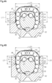
FIG. 4A] FIG. 4A is a cross-sectional view along a linking portion of a first return tube in the ball screw device inFIG. 3 , taken along line IVA-IVA inFIG. 3 . - [
FIG. 4B] FIG. 4B is a cross-sectional view along a linking portion of a second return tube in the ball screw device inFIG. 3 , taken along line IVB-IVB inFIG. 3 . - [
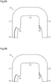
FIG. 5A] FIG. 5A is a front view of the first return tube provided in the ball screw device inFIG. 3 . - [
FIG. 5B] FIG. 5B is a front view of the second return tube provided in the ball screw device inFIG. 3 . - [
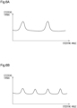
FIG. 6A] FIG. 6A is a graph showing a relation between a steering angle and steering torque in a steering system according to a comparative example. - [
FIG. 6B] FIG. 6B is a graph showing a relation between a steering angle and steering torque in the steering system inFIG. 1 . - [
FIG. 7A] FIG. 7A is a cross-sectional view taken along a linking portion of a first return tube in a ball screw device according to a second embodiment. - [
FIG. 7B] FIG. 7B is a cross-sectional view taken along a linking portion of a second return tube in the ball screw device according to the second embodiment. - [
FIG. 8] FIG. 8 is a side view of a ball screw device according to a third embodiment. - [
FIG. 9A] FIG. 9A is a cross-sectional view along a linking portion of a first return tube in the ball screw device inFIG. 8 , and is a cross-sectional view of the ball screw device along line IXA-IXA inFIG. 8 . - [
FIG. 9B] FIG. 9B is a cross-sectional view along a linking portion of a second return tube in the ball screw device inFIG. 8 , and is a cross-sectional view of the ball screw device along line IXB-IXB inFIG. 8 . - A first embodiment of a ball screw device and a steering system will be described below with reference to the drawings.
- The
steering system 1 illustrated inFIG. 1 steers steeredwheels 3 based on operation of asteering wheel 2 by a driver. Thesteering system 1 includes asteering shaft 11, agearbox 12, apitman arm 13, and alink mechanism 14. One end of thesteering shaft 11 is linked to thesteering wheel 2, and the other end of thesteering shaft 11 is linked to agearbox 12. Thegearbox 12 converts rotation of the steeringshaft 11 into swinging motion of thepitman arm 13. The swinging motion of thepitman arm 13 is transmitted to the steeredwheels 3 via thelink mechanism 14, thereby steering the steeredwheels 3. - The
steering system 1 also includes anelectric actuator 15 that generates an assist force to assist steering operations by the driver. Theelectric actuator 15 includes amotor 16 and aspeed reducer 17. Thespeed reducer 17 is, for example, a worm and wheel. Themotor 16 is linked to the steeringshaft 11 via thespeed reducer 17. Theelectric actuator 15 applies an assist force to the steeringshaft 11 by transmitting rotation of themotor 16 to the steeringshaft 11 with the speed thereof reduced by thespeed reducer 17. That is to say, thesteering system 1 according to the present embodiment is an electric power steering system. - As illustrated in
FIG. 2 , thegearbox 12 is an RBS type gearbox having aball screw device 21. In addition to theball screw device 21, thegearbox 12 includes ahousing 22 and asector shaft 23 having asector portion 24. - The
housing 22 has, for example, amain unit portion 25 and a bulgingportion 26. Themain unit portion 25 has, for example, a tubular shape with one end thereof closed. The bulgingportion 26 is provided on a peripheral wall of themain unit portion 25, and an inside of the bulgingportion 26 communicates with an inside of themain unit portion 25. The bulgingportion 26 has, for example, a tubular shape extending in a direction perpendicular to an axial direction of themain unit portion 25. Note that in the following description, for convenience of description, the closed side of thehousing 22 will be referred to as a lower side, and the open side of thehousing 22 will be referred to as an upper side. A housing that is omitted from illustration, of thespeed reducer 17, is fixed to the upper side of thehousing 22. - Note that it is sufficient for the term "tubular" as used in the present specification to be an arrangement that can be deemed to be a tubular shape overall, and tubular shapes formed by combining a plurality of components, and shapes formed by partially notching out into a letter-C shaped part or the like, are included therein. The term "tubular" shape encompasses, circles, ellipses, and polygons with sharp corners or rounded corners, but is not limited thereto.
- The
sector shaft 23 is housed in the bulgingportion 26. Thesector shaft 23 is rotatably supported via a bearing that is omitted from illustration. Thesector shaft 23 has an outer end portion exposed to an outside of thehousing 22. A basal end portion of thepitman arm 13 is fixed to the outer end portion of thesector shaft 23, so as to be integrally rotatable therewith. - The
sector portion 24 is disposed within the bulgingportion 26. Thesector portion 24 has, for example, a fan-like shape as viewed in the axial direction of thesector shaft 23. Thesector portion 24 has a plurality ofouter teeth 27 provided on an outer peripheral face thereof. - The
ball screw device 21 includes ascrew shaft 31 that is linked to the steeringshaft 11, aball screw nut 32 that meshes with theouter teeth 27 of thesector portion 24, and a plurality ofballs 33. Theball screw device 21 converts rotation of thescrew shaft 31 in accordance with rotation of the steeringshaft 11 into linear movement of theball screw nut 32. Thus, thesector shaft 23 rotates, causing thepitman arm 13 to swing. - As illustrated in
FIG. 2 andFIG. 3 , theball screw device 21 includes a plurality of return tubes, and thus has a plurality of independent circulation paths through which theballs 33 circulate. Specifically, theball screw device 21 includes afirst return tube 34, asecond return tube 35, and aholder 36, in addition to thescrew shaft 31, theball screw nut 32, and the plurality ofballs 33. Theball screw device 21 has two circulation paths, a first circulation path and a second circulation path. Note that the return tubes are sometimes referred to as circulators. Each component of theball screw device 21 will be described in detail below. - As illustrated in
FIG. 2 , thescrew shaft 31 is rotatably housed within themain unit portion 25. Thescrew shaft 31 is rotatably supported viabearings main unit portion 25, for example. The upper side end portion of thescrew shaft 31 is linked to the steeringshaft 11 so as to be integrally rotatable therewith. Agroove 43 that is helical is provided on an outer peripheral face of thescrew shaft 31. Note that the terms "upper side" and "lower side" refer to, for example, the upper side and the lower side respectively, in an up-down direction of the vehicle. - As illustrated in
FIG. 2 ,FIG. 3 ,FIG. 4A and FIG. 4B , theball screw nut 32 has a tubular shape. The ball screwnut 32 according to the present embodiment has a square outer peripheral shape and also a circular inner peripheral shape as viewed in the axial direction. The ball screwnut 32 hasrack teeth 44 on one outer side face thereof. Therack teeth 44 mesh with theouter teeth 27 of thesector portion 24. The ball screwnut 32 has an inner peripheral face provided with agroove 45 that is helical. - The
groove 43 of thescrew shaft 31 faces thegroove 45 of theball screw nut 32 to form a rolling path Rc that is helical. The plurality ofballs 33 are disposed in the rolling path Rc in a state of being interposed between thegrooves ball screw nut 32 is fitted onto the outer periphery of thescrew shaft 31 via theballs 33. - The ball screw
nut 32 has an attachingface 46 to which thefirst return tube 34 and thesecond return tube 35 are attached. The attachingface 46 is, for example, the outer side face of theball screw nut 32 that is on the opposite side from the face on which therack teeth 44 are provided. The attachingface 46 has a planar form, for example. Thefirst return tube 34 and thesecond return tube 35 are arranged side by side on the attachingface 46 such that thefirst return tube 34 is situated above thesecond return tube 35. The attachingface 46 is configured such that thefirst return tube 34 and thesecond return tube 35 are attached from the same attaching direction. The attaching direction is, for example, a direction perpendicular to the axial direction of theball screw nut 32, i.e., the direction perpendicular to the attachingface 46. The attachingface 46 is provided with a first attachingportion 47 for attaching thefirst return tube 34 and a second attachingportion 48 for attaching thesecond return tube 35. Configurations of the first attachingportion 47 and the second attachingportion 48 will be described later. - As illustrated in
FIG. 4A, FIG. 4B ,FIG. 5A and FIG. 5B , thefirst return tube 34 has a return path R1 that creates a connection between two points of the rolling path Rc. Thesecond return tube 35 has a return path R2 that creates a connection between two other points that are different from the above two points on the rolling path Rc. A section of the rolling path Rc for which a connection is created by thefirst return tube 34 does not overlap with a section of the rolling path Rc for which a connection is created by thesecond return tube 35. The return path R1 of thefirst return tube 34 and the rolling path Rc form a first circulation path, and the return path R2 of thesecond return tube 35 and the rolling path Rc form a second circulation path. - As illustrated in
FIG. 4A andFIG. 5A , thefirst return tube 34 has afirst leg portion 51, asecond leg portion 52, and a linkingportion 53 that links thefirst leg portion 51 and thesecond leg portion 52 to each other. Inner circumferential faces of thefirst leg portion 51, thesecond leg portion 52 and the linkingportion 53 form the return path R1. Thefirst return tube 34 has of shape of a tubular pipe bent into a substantially letter-C shape, for example. - Specifically, the
first leg portion 51 has a tubular shape that extends linearly along the attaching direction. Thesecond leg portion 52 has a tubular shape that extends linearly along the attaching direction. That is to say, thesecond leg portion 52 extends parallel to thefirst leg portion 51. The linkingportion 53 has a tubular shape. The linkingportion 53 extends, for example, in a direction that is perpendicular to the attaching direction and that also intersects the axial direction of theball screw nut 32. Also, both end portions of the linkingportion 53 are bent so as to be linked to thefirst leg portion 51 and thesecond leg portion 52. - A distal end of the
first leg portion 51 is provided with atongue portion 54 and afitting portion 55. Thetongue portion 54 protrudes from an inner side portion of the distal end of thefirst leg portion 51 in the attaching direction. Thetongue portion 54 has, for example, a semicircular shape as viewed in a longitudinal direction of the linkingportion 53. Thefitting portion 55 protrudes in the attaching direction from an outer side portion of the distal end of thefirst leg portion 51. Thefitting portion 55 has, for example, a semicylindrical shape. Thefitting portion 55 protrudes beyond thetongue portion 54. - The
second leg portion 52 has a shape that is symmetrical to thefirst leg portion 51 with respect to a straight line extending in the attaching direction. That is to say, a distal end of thesecond leg portion 52 is provided with atongue portion 56 and afitting portion 57. Also, a length L11 of thefirst leg portion 51 along the attaching direction, i.e., a distance from the linkingportion 53 to the distal end of thefitting portion 55, is equal to L12 of thesecond leg portion 52 along the attaching direction, i.e., a distance from the linkingportion 53 to a distal end of thefitting portion 57. - As illustrated in
FIG. 4B andFIG. 5B , thesecond return tube 35 has a similar configuration to thefirst return tube 34, except for dimensions thereof, which will be described below. That is to say, thesecond return tube 35 has afirst leg portion 61, asecond leg portion 62, and a linkingportion 63 that links thefirst leg portion 61 and thesecond leg portion 62 to each other. Thefirst leg portion 61 has atongue portion 64 and afitting portion 65. Thesecond leg portion 62 has atongue portion 66 and afitting portion 67. - As illustrated in
FIG. 3 ,FIG. 4A, and FIG. 4B , the first attachingportion 47 has a first throughhole 71 into which thefirst leg portion 51 of thefirst return tube 34 is inserted, and a second throughhole 72 into which thesecond leg portion 52 of thefirst return tube 34 is inserted. The second attachingportion 48 has a first throughhole 73 into which thefirst leg portion 61 of thesecond return tube 35 is inserted, and a second throughhole 74 into which thesecond leg portion 62 of thesecond return tube 35 is inserted. The first throughholes holes holes holes first return tube 34 and thesecond return tube 35 are attached to theball screw nut 32 from the same attaching direction, as described above. - The first through
hole 71 and the second throughhole 72 of the first attachingportion 47 are provided at positions corresponding to the above two points of the rolling path Rc between which a connection is created by thefirst return tube 34 as viewed in the attaching direction. The first throughhole 71 and the second throughhole 72 are, for example, circular holes as viewed in the attaching direction. A bore diameter of the first throughhole 71 is set to be larger than the width of thegroove 45 in the axial direction. Thus, an arc-shaped step is provided between an inner circumferential face of the first throughhole 71 and an inner face of thegroove 45 as viewed in the attaching direction. In other words, the first throughhole 71 has a bottom face that is arc-shaped as viewed in the attaching direction. A depth of the first throughhole 71, i.e., a distance between the attachingface 46 and the bottom face (step) of the first throughhole 71, is equal to thelength L 11 of thefirst leg portion 51 of thefirst return tube 34. - The second through
hole 72 has a shape symmetrical to the first throughhole 71 with respect to a straight line extending in the attaching direction. A depth of the second throughhole 72, i.e., a distance between the attachingface 46 and the bottom face (step) of the second throughhole 72, is equal to thelength L 12 of thesecond leg portion 52 of thefirst return tube 34. - When the
first return tube 34 is attached to the first attachingportion 47, a distal end of thefitting portion 55 of thefirst leg portion 51 abuts against the bottom face of the first throughhole 71, and also the distal end of thefitting portion 57 of thesecond leg portion 52 abuts against the bottom face of the second throughhole 72. Thus, the return path R1 of thefirst return tube 34 creates a connection between two points on the rolling path Rc, thereby forming the first circulation path. - The first through
hole 73 and the second throughhole 74 of the second attachingportion 48 are provided at positions corresponding to the above two other points of the rolling path Rc between which a connection is created by thesecond return tube 35 as viewed in the attaching direction. The first throughhole 73 and the second throughhole 74 are, for example, circular holes as viewed in the attaching direction. A bore diameter of the first throughhole 73 is set to be greater than the width of thegroove 45 in the axial direction. Thus, an arc-shaped step is provided between an inner circumferential face of the first throughhole 73 and the inner face of thegroove 45 as viewed in the attaching direction. In other words, the first throughhole 73 has a bottom face that is arc-shaped as viewed in the attaching direction. A depth of the first throughhole 73, i.e., a distance between the attachingface 46 and the bottom face (step) of the first throughhole 73, is equal to a length L21 of thefirst leg portion 61 of thesecond return tube 35. - The second through
hole 74 has a shape symmetrical to the first throughhole 73 with respect to a straight line extending in the attaching direction. A depth of the second throughhole 74, i.e., a distance between the attachingface 46 and a bottom face (step) of the second throughhole 74, is equal to a length L22 of thesecond leg portion 62 of thesecond return tube 35. - When the
second return tube 35 is attached to the second attachingportion 48, a distal end of thefitting portion 65 of thefirst leg portion 61 abuts against the bottom face of the first throughhole 73, and also a distal end of thefitting portion 67 of thesecond leg portion 62 abuts against the bottom face of the second throughhole 74. Thus, the return path R2 of thesecond return tube 35 creates a connection between two points on the rolling path Rc, thereby forming the second circulation path. - As illustrated in
FIG. 3 , as viewed from the attaching direction, distances from an axial line AX of theball screw nut 32 to the first throughholes ball screw nut 32 to the second throughholes holes holes FIG. 3 . A straight line linking the center of the first throughhole 71 and the center of the second throughhole 72 in the first attachingportion 47 is parallel to a straight line linking the center of the first throughhole 73 and the center of the second throughhole 74 in the second attachingportion 48. Thus, the linkingportion 53 of thefirst return tube 34 attached to theball screw nut 32 becomes parallel to the linkingportion 63 of thesecond return tube 35. - As illustrated in
FIG. 2 andFIG. 3 , theholder 36 fixes thefirst return tube 34 and thesecond return tube 35 to theball screw nut 32. Theholder 36 has, for example, an elongated plate shape. Theholder 36 has a first recessedportion 81 and a second recessedportion 82. The linkingportion 53 of thefirst return tube 34 is fit into the first recessedportion 81. The linkingportion 63 of thesecond return tube 35 is fit into the second recessedportion 82. Theholder 36 is fixed to the attachingface 46 of theball screw nut 32 bybolts 83. Thus, theholder 36 presses and fixes thefirst return tube 34 and thesecond return tube 35 against the attachingface 46 of theball screw nut 32. - In the
ball screw device 21 configured in this way, theballs 33 roll within the rolling path Rc while receiving frictional force from thescrew shaft 31 and theball screw nut 32 in accordance with rotation of thescrew shaft 31. When theballs 33 rolling in the first circulation path roll in the rolling path Rc and reach one of the two points between which a connection is created by thefirst return tube 34, theballs 33 are discharged to the other by passing through the return path R1. Thus, theballs 33 move from a downstream side to an upstream side along the rolling path Rc and circulate through the first circulation path. Note that within the return path R1, as anew ball 33 enters the return path R1 from the rolling path Rc, theball 33 is pushed by anadjacent ball 33 located behind in a circulation direction and moves through the return path R1. - Of the two end portions of the
first return tube 34, the end portion that serves as an entrance for theballs 33 to enter the return path R1 when thescrew shaft 31 rotates clockwise inFIG. 4A and that serves as an exit for theballs 33 to be discharged from the return path R1 when thescrew shaft 31 rotates counterclockwise is defined as afirst end portion 91. Also, of the two end portions of thefirst return tube 34, the end portion that serves as the exit for theballs 33 to be discharged from the return path R1 when thescrew shaft 31 rotates clockwise and that serves as the entrance for theballs 33 to enter the return path R1 when thescrew shaft 31 rotates counterclockwise is defined as asecond end portion 92. When thefirst leg portion 51 is inserted into the first throughhole 71 and also thesecond leg portion 52 is inserted into the second throughhole 72, as in the present embodiment, thefirst leg portion 51 includes thefirst end portion 91 and thesecond leg portion 52 includes thesecond end portion 92. - In the same way, when the
balls 33 rolling in the second circulation path roll in the rolling path Rc and reach one of the two points between which a connection is created by thesecond return tube 35, theballs 33 are discharged to the other by passing through the return path R2. Thus, theballs 33 move from the downstream side to the upstream side along the rolling path Rc and circulate through the second circulation path. As described above, the section of the rolling path Rc for which a connection is created by thefirst return tube 34 does not overlap with the section for which a connection is created by thesecond return tube 35. Accordingly, theballs 33 circulating in the first circulation path do not pass through the second circulation path, but circulate only within the first circulation path. In the same way, theballs 33 circulating in the second circulation path do not pass through the first circulation path, but circulate only within the second circulation path. - Of the two end portions of the
second return tube 35, the end portion that serves as the entrance for theballs 33 to enter the return path R2 when thescrew shaft 31 rotates clockwise inFIG. 4B and that serves as the exit for theballs 33 to be discharged from the return path R2 when thescrew shaft 31 rotates counterclockwise is defined as afirst end portion 93. Also, of the two end portions of thesecond return tube 35, the end portion that serves as the exit for theballs 33 to be discharged from the return path R2 when thescrew shaft 31 rotates clockwise and that serves as the entrance for theballs 33 to enter the return path R2 when thescrew shaft 31 rotates counterclockwise is defined as asecond end portion 94. When thefirst leg portion 61 is inserted into the first throughhole 73 and also thesecond leg portion 62 is inserted into the second throughhole 74, as in the present embodiment, thefirst leg portion 61 includes thefirst end portion 93 and thesecond leg portion 62 includes thesecond end portion 94. - As described above, the
ball screw device 21 has a plurality of the circulation paths. Accordingly, the length of the rolling path Rc in one circulation path can be prevented from becoming too long, while the length of the rolling path Rc in the entireball screw device 21 can be increased. Thus, increasing the number ofballs 33 rolling within the rolling path Rc enables a load (i.e., frictional force) applied to each of the plurality ofballs 33 from thescrew shaft 31 and theball screw nut 32 to be reduced. Accordingly, the life of theballs 33, and hence the life of theball screw device 21, can be extended. Furthermore, the length of the rolling path Rc in one circulation path does not become too long, and accordingly contact betweenballs 33 that are adjacent within the rolling path Rc can be suppressed, for example, allowing theball screw device 21 to operate smoothly. - Here, as a result of extensive research, the present inventors have discovered that torque required to rotate the
screw shaft 31, i.e., steering torque, varies depending on the timing at which theballs 33 enter the return tube and the timing at which theballs 33 are discharged from the return tube. Note that the timing at which at least a part of aball 33 is in a state of coming into contact with the return tube is the timing at which theball 33 enters the return tube, and the timing at which theball 33 is no longer in a state of being in contact with the return tube is the timing at which theball 33 is discharged from the return tube. - Accordingly, in a
ball screw device 21 having multiple circulation paths as in the present embodiment, when a timing at which aball 33 enters thefirst return tube 34 and a timing at which aball 33 enters thesecond return tube 35 coincide with each other, the fluctuation in steering torque will be great. Also, when the timing at which aball 33 is discharged from thefirst return tube 34 and the timing at which aball 33 is discharged from thesecond return tube 35 coincide with each other, the fluctuation in the steering torque also becomes great. - Taking this point into consideration, in the
ball screw device 21, the timings of theballs 33 entering and exiting thefirst return tube 34 and thesecond return tube 35 are actively offset. Here, the position of thefirst end portion 93 of thesecond return tube 35 relative to the position of thefirst end portion 91 of thefirst return tube 34 in a circumferential direction of theball screw nut 32 is defined as a first relative position. Also, the position of thesecond end portion 94 of thesecond return tube 35 relative to the position of thesecond end portion 92 of thefirst return tube 34 in the circumferential direction of theball screw nut 32 is defined as a second relative position. When defined in this way, both the first relative position and the second relative position include offset in the circumferential direction. This can be understood by overlayingFIG. 4A and FIG. 4B , in which the position of thefirst end portion 91 of thefirst return tube 34 and the position of thefirst end portion 93 of thesecond return tube 35 do not coincide with each other, but are offset in the circumferential direction of theball screw nut 32, and the position of thesecond end portion 92 of thefirst return tube 34 and the position of thesecond end portion 94 of thesecond return tube 35 do not coincide with each other, but are offset in the circumferential direction of theball screw nut 32. - Specifically, as illustrated in
FIG. 4A and FIG. 4B , the length L11 of thefirst leg portion 51 and the length L12 of thesecond leg portion 52 of thefirst return tube 34 according to the present embodiment are equal to each other. The length L21 of thefirst leg portion 61 and the length L22 of thesecond leg portion 62 of thesecond return tube 35 are equal to each other. The length L11 of thefirst leg portion 51 and the length L12 of thesecond leg portion 52 of thefirst return tube 34 are longer than the length L21 of thefirst leg portion 61 and the length L22 of thesecond leg portion 62 of thesecond return tube 35. Note that a length L13 of the linkingportion 53 of thefirst return tube 34 and a length L23 of the linkingportion 63 of thesecond return tube 35 are equal with each other. - Thus, the
first end portion 93 and thesecond end portion 94 of thesecond return tube 35 are located closer to the attachingface 46 than thefirst end portion 91 and thesecond end portion 92 of thefirst return tube 34. That is to say, both the first relative position and the second relative position include an offset in the circumferential direction of theball screw nut 32. Also, the sum of the amount of circumferential-direction offset of the first relative position and the amount of circumferential-direction offset of the second relative position is different from an integer multiple of the diameter of theball 33. The sum of offset in the present embodiment is, for example, smaller than the diameter of theballs 33, but may be larger than the diameter of theballs 33. - Next, the functions and effects of the present embodiment will be described.
- (1-1) As described above, the
ball screw device 21 has the plurality of circulation paths, and accordingly the length of the rolling path Rc in the entireball screw device 21 can be increased while suppressing the length of the rolling path Rc in one circulation path from becoming too long. Accordingly, reducing the load applied to each of the plurality ofballs 33 enables the life of theballs 33, and hence the life of theball screw device 21, to be extended. - Here, as a comparative example, a ball screw device will be assumed that is configured similarly to the
ball screw device 21 except that neither the first relative position nor the second relative position includes offset in the circumferential direction. That is to say, in the comparative example, the position of the first end portion of the first return tube in the circumferential direction of the ball screw nut coincides with the position of the first end portion of the second return tube, and also the position of the second end portion of the first return tube in the circumferential direction of the ball screw nut coincides with the position of the second end portion of the second return tube. - Thus, the timing at which the ball enters the first return tube and the timing at which the ball enters the second return tube, and the timing at which the ball is discharged from the first return tube and the timing at which the ball is discharged from the second return tube, readily coincide with each other. As a result, as shown in
FIG. 6A , for example, in the ball screw device according to the comparative example, when steering is performed at a constant steering speed, a rotation angle of thescrew shaft 31, i.e., the steering torque varies greatly with respect to the steering angle. - With respect to this point, in the
ball screw device 21 according to the present embodiment, both the first relative position and the second relative position include offset in the circumferential direction. Accordingly, in at least one of the timing at which theball 33 enters thefirst return tube 34 and the timing at which theball 33 enters thesecond return tube 35, and the timing at which theball 33 is discharged from thefirst return tube 34 and the timing at which theball 33 is discharged from thesecond return tube 35, the timings are likely to be offset with each other. Thus, for example, as shown inFIG. 6B , in theball screw device 21 according to the present embodiment, when steering is performed at a constant steering speed, the fluctuation in steering torque relative to the steering angle is reduced. Thus, smooth operation of theball screw device 21 can be ensured. - Note that in the comparative example, the layout of the balls in the return path in the first return tube and the layout of the balls in the return path in the first return tube do not necessarily match each other. For example, the balls may be laid out in a zigzag (staggered) pattern in the first return tube and also the balls may be laid out in a straight line in the second return tube. As a result, the timing at which the balls are discharged from the first return tube may be offset from the timing at which the balls are discharged from the second return tube. However, such offset in timing occurs by chance. Accordingly, in the ball screw device according to the comparative example, the timing at which the ball enters the first return tube and the timing at which the ball enters the second return tube, and the timing at which the ball is discharged from the first return tube and the timing at which the ball is discharged from the second return tube, readily coincide with each other.
- (1-2) The
steering system 1 includes theball screw device 21 and the steeringshaft 11 linked to thescrew shaft 31. According to the above configuration, fluctuations in steering torque are suppressed, and accordingly deterioration of steering feeling can be suppressed. - (1-3) The sum of the amount of offset of the first relative position in the circumferential direction and the amount of offset of the second relative position in the circumferential direction is different from an integer multiple of the diameter of the
ball 33. Accordingly, in at least one of the timing at which theball 33 enters thefirst return tube 34 and the timing at which theball 33 enters thesecond return tube 35, and the timing at which theball 33 is discharged from thefirst return tube 34 and the timing at which theball 33 is discharged from thesecond return tube 35, the timings are suitably readily offset from each other. - (1-4) The
return tubes first leg portion second leg portion first leg portion 51 and the length L12 of thesecond leg portion 52 of thefirst return tube 34 are equal to each other. The length L21 of thefirst leg portion 61 and the length L22 of thesecond leg portion 62 of thesecond return tube 35 are equal to each other. - According to the above configuration, the
first leg portion 51 of thefirst return tube 34 can be inserted into either the first throughhole 71 or the second throughhole 72, and also thesecond leg portion 52 can be inserted into either the first throughhole 71 or the second throughhole 72. Accordingly, when attaching thefirst return tube 34, it is not necessary to take into consideration the combination of thefirst leg portion 51 and the first throughhole 71, and the combination of thesecond leg portion 52 and the second throughhole 72. This facilitates work of attaching thefirst return tube 34. In the same way, thefirst leg portion 61 of thesecond return tube 35 can be inserted into either the first throughhole 73 or the second throughhole 74, and also thesecond leg portion 62 can be inserted into either the first throughhole 73 or the second throughhole 74. This facilitates work of attaching thesecond return tube 35. - Next, a second embodiment of a ball screw device and a steering system will be described below with reference to the drawings. Note that for convenience of description, the same configurations are denoted by the same signs as those in the first embodiment, and description thereof will be omitted.
- As illustrated in
FIG. 7A and FIG. 7B , the length L11 of thefirst leg portion 51 of thefirst return tube 34 is longer than the length L12 of thesecond leg portion 52 in the present embodiment. The length L21 of thefirst leg portion 61 of thesecond return tube 35 is shorter than the length L22 of thesecond leg portion 62. The length L11 of thefirst leg portion 51 of thefirst return tube 34 and the length L22 of thesecond leg portion 62 of thesecond return tube 35 are equal to each other. The length L12 of thesecond leg portion 52 of thefirst return tube 34 and the length L21 of thefirst leg portion 61 of thesecond return tube 35 are equal to each other. The length L13 of the linkingportion 53 of thefirst return tube 34 and the length L23 of the linkingportion 63 of thesecond return tube 35 are equal to each other. - Thus, the
first end portion 93 of thesecond return tube 35 is located closer to the attachingface 46 than thefirst end portion 91 of thefirst return tube 34 is. Also, thesecond end portion 92 of thefirst return tube 34 is located closer to the attachingface 46 than thesecond end portion 94 of thesecond return tube 35 is. That is to say, both the first relative position and the second relative position include an offset in the circumferential direction of theball screw nut 32. Also, the sum of the amount of circumferential-direction offset of the first relative position and the amount of circumferential-direction offset of the second relative position is different from an integer multiple of the diameter of theball 33. The sum of offset in the present embodiment is, for example, smaller than the diameter of theballs 33, but may be larger than the diameter of theballs 33. - The present embodiment described above has the following functions and effects in addition to the functions and effects that are similar to the functions and effects described above in (1-1) to (1-3) according to the first embodiment.
(2-1) Thereturn tubes first leg portions second leg portions portions first leg portions second leg portions first leg portion 51 of thefirst return tube 34 is different from the length L12 of thesecond leg portion 52 of thefirst return tube 34. The length L21 of thefirst leg portion 61 of thesecond return tube 35 is different from the length L22 of thesecond leg portion 62 of thesecond return tube 35. The length L11 of thefirst leg portion 51 of thefirst return tube 34 and the length L22 of thesecond leg portion 62 of thesecond return tube 35 are equal to each other. The length L12 of thesecond leg portion 52 of thefirst return tube 34 and the length L21 of thefirst leg portion 61 of thesecond return tube 35 are equal to each other. The length L13 of the linkingportion 53 of thefirst return tube 34 and the length L13 of the linkingportion 63 of thesecond return tube 35 are equal to each other. Accordingly, thefirst return tube 34 can be formed in the same shape as thesecond return tube 35. That is to say, thefirst return tube 34 can be used as thesecond return tube 35, and also thesecond return tube 35 can be used as thefirst return tube 34. This enables reduction in manufacturing costs, for example, as compared to a case in which the shape of thefirst return tube 34 is different from the shape of thesecond return tube 35. - Next, a third embodiment of a ball screw device and a steering system will be described below with reference to the drawings. Note that for convenience of description, the same configurations are denoted by the same signs as those in the first embodiment, and description thereof will be omitted.
- As illustrated in
FIG. 8 ,FIG. 9A, and FIG. 9B , the length L11 of thefirst leg portion 51 and the length L12 of thesecond leg portion 52 of thefirst return tube 34 according to the present embodiment are equal to each other. The length L21 of thefirst leg portion 61 and the length L22 of thesecond leg portion 62 of thesecond return tube 35 are equal to each other. The length L11 of thefirst leg portion 51 and the length L12 of thesecond leg portion 52 of thefirst return tube 34 are longer than the length L21 of thefirst leg portion 61 and the length L22 of thesecond leg portion 62 of thesecond return tube 35. The length L13 of the linkingportion 53 of thefirst return tube 34 is longer than the length L23 of the linkingportion 63 of thesecond return tube 35. - As illustrated in
FIG. 8 , the first throughhole 73 of the second attachingportion 48 is provided closer to the axial line AX of theball screw nut 32 than the first throughhole 71 of the first attachingportion 47 as viewed in the attaching direction. Also, the second throughhole 74 of the second attachingportion 48 is provided closer to the axial line AX of theball screw nut 32 than the second throughhole 72 of the first attachingportion 47. Note that for convenience of description, a straight line that passes through the center of the first throughhole 73 and is parallel to the axial line AX, and a straight line that passes through the center of the second throughhole 74 and is parallel to the axial line AX, are indicated by long dashed double-short dashed lines inFIG. 8 . A straight line connecting the center of the first throughhole 71 and the center of the second throughhole 72 in the first attachingportion 47 intersects a straight line connecting the center of the first throughhole 73 and the center of the second throughhole 74 in the second attachingportion 48. Accordingly, the linkingportion 53 of thefirst return tube 34 and the linkingportion 63 of thesecond return tube 35 are not parallel to each other. - Thus, the
first end portion 93 and thesecond end portion 94 of thesecond return tube 35 are located closer to the attachingface 46 than thefirst end portion 91 and thesecond end portion 92 of thefirst return tube 34. That is to say, both the first relative position and the second relative position include an offset in the circumferential direction of theball screw nut 32. Also, the sum of the amount of circumferential-direction offset of the first relative position and the amount of circumferential-direction offset of the second relative position is different from an integer multiple of the diameter of theball 33. The sum of offset in the present embodiment is, for example, smaller than the diameter of theballs 33, but may be larger than the diameter of theballs 33. - The present embodiment described above has the following functions and effects in addition to the functions and effects that are similar to the functions and effects described above in (1-1) to (1-4) according to the first embodiment.
(3-1) Thereturn tubes first leg portions second leg portions portions first leg portions second leg portions portion 53 of thefirst return tube 34 is different from the length L23 of the linkingportion 63 of thesecond return tube 35. Accordingly, thesecond return tube 35 cannot be attached to the first attachingportion 47, for example. This enables incorrect assembly of thefirst return tube 34 and thesecond return tube 35 to be suppressed. - Each of the above embodiments can be carried out modified as follows. The above embodiments and the following modifications can be combined with each other and carried out insofar as no technical contradiction arises.
- • The
first return tube 34 and thesecond return tube 35 are described as being fixed to theball screw nut 32 by asingle holder 36. However, this is not restrictive, and thefirst return tube 34 and thesecond return tube 35 may be fixed to theball screw nut 32 by separate holders, for example. Also, thefirst return tube 34 and thesecond return tube 35 may be fixed to theball screw nut 32 by an adhesive or the like without using a holder, for example, and the fixing method thereof can be changed as appropriate. - • The sum of the amount of offset in the circumferential direction of the first relative position and the amount of offset in the circumferential direction of the second relative position may be equal to an integer multiple of the diameter of the
ball 33. As long as at least one of the first relative position and the second relative position includes offset in the circumferential direction of theball screw nut 32, the shapes of thefirst return tube 34 and thesecond return tube 35 can be changed as appropriate. For example, in the first embodiment, the length L11 of thefirst leg portion 51 of thefirst return tube 34 may be equal to the length L21 of thefirst leg portion 61 of thesecond return tube 35. That is to say, the first relative position may not include offset in the circumferential direction, and just the second relative position may include offset in the circumferential direction. Also, for example, in the first embodiment, the length L12 of thesecond leg portion 52 of thefirst return tube 34 may be equal to the length L22 of thesecond leg portion 62 of thesecond return tube 35. That is to say, just the first relative position may include offset in the circumferential direction, and the second relative position may not include offset in the circumferential direction. Also, for example, in the second embodiment, the length L11 of thefirst leg portion 51 of thefirst return tube 34 may be made different from the length L22 of thesecond leg portion 62 of thesecond return tube 35. Also, for example, in the third embodiment, the length L11 of thefirst leg portion 51 of thefirst return tube 34 may be made to be different from the length L12 of thesecond leg portion 52 thereof. - •The
ball screw device 21 may include three or more return tubes. In this case, the relative positions of thefirst end portion 91 of thefirst return tube 34 and thefirst end portion 93 of thesecond return tube 35 with respect to the first end portions of the other return tubes may or may not include offset in the circumferential direction of theball screw nut 32. Also, the relative positions of thesecond end portion 92 of thefirst return tube 34 and thesecond end portion 94 of thesecond return tube 35 with respect to the second end portions of the other return tubes may or may not include offset in the circumferential direction of theball screw nut 32. - • The
steering system 1 may be provided with a hydraulic actuator that generates an assist force using hydraulic pressure, in addition to or instead of theelectric actuator 15. Also, thesteering system 1 does not have to be provided with an actuator that generates assist force. - • Although the
ball screw device 21 is described as being used to linearly move theball screw nut 32 by rotating thescrew shaft 31, theball screw device 21 may be used to linearly move thescrew shaft 31 by rotating theball screw nut 32. - • The
ball screw device 21 may be applied to devices other than thesteering system 1. - Next, technical ideas that can be comprehended from the above embodiments and modifications will additionally be described below.
- (Appendix 1) In one aspect of the present disclosure, each of a plurality of the attaching portions may have a first through hole that opens in the attaching direction, into which the first end portion is inserted, and a second through hole that opens in the attaching direction, into which the second end portion is inserted.
- (Appendix 2) In one aspect of the present disclosure, the ball screw nut may have a planar attaching face, and the plurality of return tubes may be disposed side by side on the attaching face.
Claims (6)
- A ball screw device, comprising:a screw shaft having a groove on an outer periphery of the screw shaft;a ball screw nut having a groove on an inner periphery of the ball screw nut; a plurality of return tubes; anda plurality of balls, whereinthe groove of the screw shaft faces the groove of the ball screw nut to form a helical rolling path,each of the plurality of return tubes includesa return path configured to create a connection between two points of the rolling path, the return path and the rolling path forming a circulation path in which the balls are disposed,a first end portion that serves as an entrance for the balls to enter the return path when the screw shaft or the ball screw nut rotates clockwise, and that serves as an exit for the balls to be discharged from the return path when the screw shaft or the ball screw nut rotates counterclockwise, anda second end portion that serves as an exit for the balls to be discharged from the return path when the screw shaft or the ball screw nut rotates clockwise, and that serves as an entrance for the balls to enter the return path when the screw shaft or the ball screw nut rotates counterclockwise,the ball screw nut has a plurality of attaching portions configured such that the plurality of return tubes is attached from a same attaching direction,the plurality of return tubes includes at least a first return tube and a second return tube,
a position of the first end portion of the second return tube relative to a position of the first end portion of the first return tube in a circumferential direction of the ball screw nut is a first relative position, and a position of the second end portion of the second return tube relative to a position of the second end portion of the first return tube in the circumferential direction is a second relative position, andat least one of the first relative position and the second relative position includes offset in the circumferential direction. - The ball screw device according to claim 1, wherein a sum of an offset amount in the circumferential direction of the first relative position and an offset amount in the circumferential direction of the second relative position is different from an integer multiple of a diameter of each of the balls.
- The ball screw device according to claim 1 or 2, whereineach of the plurality of return tubes includesa first leg portion having a length along the attaching direction, anda second leg portion having a length along the attaching direction,the length of the first leg portion of the first return tube and the length of the second leg portion of the first return tube are equal to each other, andthe length of the first leg portion of the second return tube and the length of the second leg portion of the second return tube are equal to each other.
- The ball screw device according to any one of claims 1 to 3, whereineach of the plurality of return tubes includesa first leg portion having a length along the attaching direction,a second leg portion having a length along the attaching direction, anda linking portion that links the first leg portion and the second leg portion to each other, the linking portion having a length along a direction intersecting the attaching direction, andthe length of the linking portion of the first return tube is different from the length of the linking portion of the second return tube.
- The ball screw device according to claim 1 or 2, whereineach of the plurality of return tubes includesa first leg portion having a length along the attaching direction,a second leg portion having a length along the attaching direction, anda linking portion that links the first leg portion and the second leg portion to each other, the linking portion having a length along a direction intersecting the attaching direction,the length of the first leg portion of the first return tube is different from the length of the second leg portion of the first return tube,the length of the first leg portion of the second return tube is different from the length of the second leg portion of the second return tube,the length of the first leg portion of the first return tube and the length of the second leg portion of the second return tube are equal to each other,the length of the second leg portion of the first return tube and the length of the first leg portion of the second return tube are equal to each other, andthe length of the linking portion of the first return tube and the length of the linking portion of the second return tube are equal to each other.
- A steering system, comprising:the ball screw device according to any one of claims 1 to 5; anda steering shaft linked to the screw shaft.
Applications Claiming Priority (1)
| Application Number | Priority Date | Filing Date | Title |
|---|---|---|---|
| PCT/JP2022/002420 WO2023139787A1 (en) | 2022-01-24 | 2022-01-24 | Ball screw device and steering device |
Publications (3)
| Publication Number | Publication Date |
|---|---|
| EP4471289A1 true EP4471289A1 (en) | 2024-12-04 |
| EP4471289A4 EP4471289A4 (en) | 2025-03-05 |
| EP4471289B1 EP4471289B1 (en) | 2026-05-06 |
Family
ID=87348449
Family Applications (1)
| Application Number | Title | Priority Date | Filing Date |
|---|---|---|---|
| EP22921944.9A Active EP4471289B1 (en) | 2022-01-24 | 2022-01-24 | Ball screw device and steering device |
Country Status (4)
| Country | Link |
|---|---|
| EP (1) | EP4471289B1 (en) |
| JP (1) | JP7639949B2 (en) |
| CN (1) | CN118575020A (en) |
| WO (1) | WO2023139787A1 (en) |
Families Citing this family (1)
| Publication number | Priority date | Publication date | Assignee | Title |
|---|---|---|---|---|
| WO2025224830A1 (en) * | 2024-04-23 | 2025-10-30 | 株式会社ジェイテクト | Ball screw device and electric power steering device |
Family Cites Families (3)
| Publication number | Priority date | Publication date | Assignee | Title |
|---|---|---|---|---|
| JP6651892B2 (en) * | 2016-02-22 | 2020-02-19 | 日本精工株式会社 | Ball screw, ball screw out-of-circuit ball detection method |
| JP2018105397A (en) * | 2016-12-26 | 2018-07-05 | 日本精工株式会社 | Ball screw |
| JP7118673B2 (en) | 2018-03-12 | 2022-08-16 | クノールブレムゼステアリングシステムジャパン株式会社 | steering device |
-
2022
- 2022-01-24 JP JP2023575028A patent/JP7639949B2/en active Active
- 2022-01-24 WO PCT/JP2022/002420 patent/WO2023139787A1/en not_active Ceased
- 2022-01-24 CN CN202280089210.5A patent/CN118575020A/en active Pending
- 2022-01-24 EP EP22921944.9A patent/EP4471289B1/en active Active
Also Published As
| Publication number | Publication date |
|---|---|
| WO2023139787A1 (en) | 2023-07-27 |
| EP4471289A4 (en) | 2025-03-05 |
| JP7639949B2 (en) | 2025-03-05 |
| CN118575020A (en) | 2024-08-30 |
| EP4471289B1 (en) | 2026-05-06 |
| JPWO2023139787A1 (en) | 2023-07-27 |
Similar Documents
| Publication | Publication Date | Title |
|---|---|---|
| US9151371B2 (en) | Ball screw device having tunnel raceway | |
| EP1524173B1 (en) | Electric power steering apparatus | |
| JP4241572B2 (en) | Electric power steering device for vehicles | |
| CN109923767B (en) | Electric Actuator | |
| EP4471289B1 (en) | Ball screw device and steering device | |
| EP3326890B1 (en) | Ball screw device and steering system including ball screw device | |
| CN108027028A (en) | Actuator | |
| WO2005000662A1 (en) | Electric power steering device | |
| EP3255308A1 (en) | Ball screw mechanism and steering system | |
| US6374693B1 (en) | Variable steering ratio steering system | |
| EP2578902A1 (en) | Cam device | |
| JPH11210858A (en) | Circulation type screw device | |
| CN110775147A (en) | Steering device | |
| US20060151235A1 (en) | Steering device | |
| EP1281894B1 (en) | Ball screw apparatus | |
| JP2019537694A (en) | Fixed bearings and steering gears | |
| JP2000355278A (en) | Ball screw for steering and power steering device using the same | |
| JP6365702B2 (en) | Electric power steering device | |
| JP7015752B2 (en) | Electric power steering device | |
| CN111824240A (en) | Ball screw device | |
| JP4516479B2 (en) | Rotational linear motion conversion mechanism | |
| EP1840414B1 (en) | Gear device and electric power steering apparatus | |
| CN112313430A (en) | Ball screw | |
| EP3922885B1 (en) | Ball screw device | |
| JP6263373B2 (en) | Differential case |
Legal Events
| Date | Code | Title | Description |
|---|---|---|---|
| STAA | Information on the status of an ep patent application or granted ep patent |
Free format text: STATUS: THE INTERNATIONAL PUBLICATION HAS BEEN MADE |
|
| PUAI | Public reference made under article 153(3) epc to a published international application that has entered the european phase |
Free format text: ORIGINAL CODE: 0009012 |
|
| STAA | Information on the status of an ep patent application or granted ep patent |
Free format text: STATUS: REQUEST FOR EXAMINATION WAS MADE |
|
| 17P | Request for examination filed |
Effective date: 20240730 |
|
| AK | Designated contracting states |
Kind code of ref document: A1 Designated state(s): AL AT BE BG CH CY CZ DE DK EE ES FI FR GB GR HR HU IE IS IT LI LT LU LV MC MK MT NL NO PL PT RO RS SE SI SK SM TR |
|
| A4 | Supplementary search report drawn up and despatched |
Effective date: 20250131 |
|
| RIC1 | Information provided on ipc code assigned before grant |
Ipc: B62D 5/04 20060101ALI20250127BHEP Ipc: F16H 25/22 20060101AFI20250127BHEP |
|
| DAV | Request for validation of the european patent (deleted) | ||
| DAX | Request for extension of the european patent (deleted) | ||
| GRAP | Despatch of communication of intention to grant a patent |
Free format text: ORIGINAL CODE: EPIDOSNIGR1 |
|
| STAA | Information on the status of an ep patent application or granted ep patent |
Free format text: STATUS: GRANT OF PATENT IS INTENDED |
|
| RIC1 | Information provided on ipc code assigned before grant |
Ipc: F16H 25/22 20060101AFI20251114BHEP Ipc: B62D 5/04 20060101ALI20251114BHEP |
|
| INTG | Intention to grant announced |
Effective date: 20251208 |
|
| GRAS | Grant fee paid |
Free format text: ORIGINAL CODE: EPIDOSNIGR3 |
|
| GRAA | (expected) grant |
Free format text: ORIGINAL CODE: 0009210 |
|
| STAA | Information on the status of an ep patent application or granted ep patent |
Free format text: STATUS: THE PATENT HAS BEEN GRANTED |
|
| AK | Designated contracting states |
Kind code of ref document: B1 Designated state(s): AL AT BE BG CH CY CZ DE DK EE ES FI FR GB GR HR HU IE IS IT LI LT LU LV MC MK MT NL NO PL PT RO RS SE SI SK SM TR |
|
| REG | Reference to a national code |
Ref country code: CH Ref legal event code: F10 Free format text: ST27 STATUS EVENT CODE: U-0-0-F10-F00 (AS PROVIDED BY THE NATIONAL OFFICE) Effective date: 20260506 Ref country code: GB Ref legal event code: FG4D |