EP4471286A1 - Pressure balancing of rotating control piston of generator transmission - Google Patents
Pressure balancing of rotating control piston of generator transmission Download PDFInfo
- Publication number
- EP4471286A1 EP4471286A1 EP24168218.6A EP24168218A EP4471286A1 EP 4471286 A1 EP4471286 A1 EP 4471286A1 EP 24168218 A EP24168218 A EP 24168218A EP 4471286 A1 EP4471286 A1 EP 4471286A1
- Authority
- EP
- European Patent Office
- Prior art keywords
- chamber
- piston
- clutch
- pressure
- control
- Prior art date
- Legal status (The legal status is an assumption and is not a legal conclusion. Google has not performed a legal analysis and makes no representation as to the accuracy of the status listed.)
- Pending
Links
Images


Classifications
-
- B—PERFORMING OPERATIONS; TRANSPORTING
- B64—AIRCRAFT; AVIATION; COSMONAUTICS
- B64D—EQUIPMENT FOR FITTING IN OR TO AIRCRAFT; FLIGHT SUITS; PARACHUTES; ARRANGEMENT OR MOUNTING OF POWER PLANTS OR PROPULSION TRANSMISSIONS IN AIRCRAFT
- B64D27/00—Arrangement or mounting of power plants in aircraft; Aircraft characterised by the type or position of power plants
- B64D27/02—Aircraft characterised by the type or position of power plants
- B64D27/10—Aircraft characterised by the type or position of power plants of gas-turbine type
-
- B—PERFORMING OPERATIONS; TRANSPORTING
- B64—AIRCRAFT; AVIATION; COSMONAUTICS
- B64D—EQUIPMENT FOR FITTING IN OR TO AIRCRAFT; FLIGHT SUITS; PARACHUTES; ARRANGEMENT OR MOUNTING OF POWER PLANTS OR PROPULSION TRANSMISSIONS IN AIRCRAFT
- B64D35/00—Transmitting power from power plants to propellers or rotors; Arrangements of transmissions
-
- F—MECHANICAL ENGINEERING; LIGHTING; HEATING; WEAPONS; BLASTING
- F01—MACHINES OR ENGINES IN GENERAL; ENGINE PLANTS IN GENERAL; STEAM ENGINES
- F01D—NON-POSITIVE DISPLACEMENT MACHINES OR ENGINES, e.g. STEAM TURBINES
- F01D15/00—Adaptations of machines or engines for special use; Combinations of engines with devices driven thereby
- F01D15/10—Adaptations for driving, or combinations with, electric generators
-
- F—MECHANICAL ENGINEERING; LIGHTING; HEATING; WEAPONS; BLASTING
- F02—COMBUSTION ENGINES; HOT-GAS OR COMBUSTION-PRODUCT ENGINE PLANTS
- F02C—GAS-TURBINE PLANTS; AIR INTAKES FOR JET-PROPULSION PLANTS; CONTROLLING FUEL SUPPLY IN AIR-BREATHING JET-PROPULSION PLANTS
- F02C7/00—Features, components parts, details or accessories, not provided for in, or of interest apart form groups F02C1/00 - F02C6/00; Air intakes for jet-propulsion plants
- F02C7/32—Arrangement, mounting, or driving, of auxiliaries
-
- F—MECHANICAL ENGINEERING; LIGHTING; HEATING; WEAPONS; BLASTING
- F16—ENGINEERING ELEMENTS AND UNITS; GENERAL MEASURES FOR PRODUCING AND MAINTAINING EFFECTIVE FUNCTIONING OF MACHINES OR INSTALLATIONS; THERMAL INSULATION IN GENERAL
- F16D—COUPLINGS FOR TRANSMITTING ROTATION; CLUTCHES; BRAKES
- F16D13/00—Friction clutches
- F16D13/22—Friction clutches with axially-movable clutching members
- F16D13/38—Friction clutches with axially-movable clutching members with flat clutching surfaces, e.g. discs
- F16D13/52—Clutches with multiple lamellae ; Clutches in which three or more axially moveable members are fixed alternately to the shafts to be coupled and are pressed from one side towards an axially-located member
-
- F—MECHANICAL ENGINEERING; LIGHTING; HEATING; WEAPONS; BLASTING
- F16—ENGINEERING ELEMENTS AND UNITS; GENERAL MEASURES FOR PRODUCING AND MAINTAINING EFFECTIVE FUNCTIONING OF MACHINES OR INSTALLATIONS; THERMAL INSULATION IN GENERAL
- F16D—COUPLINGS FOR TRANSMITTING ROTATION; CLUTCHES; BRAKES
- F16D25/00—Fluid-actuated clutches
- F16D25/06—Fluid-actuated clutches in which the fluid actuates a piston incorporated in, i.e. rotating with the clutch
- F16D25/062—Fluid-actuated clutches in which the fluid actuates a piston incorporated in, i.e. rotating with the clutch the clutch having friction surfaces
- F16D25/063—Fluid-actuated clutches in which the fluid actuates a piston incorporated in, i.e. rotating with the clutch the clutch having friction surfaces with clutch members exclusively moving axially
- F16D25/0635—Fluid-actuated clutches in which the fluid actuates a piston incorporated in, i.e. rotating with the clutch the clutch having friction surfaces with clutch members exclusively moving axially with flat friction surfaces, e.g. discs
- F16D25/0638—Fluid-actuated clutches in which the fluid actuates a piston incorporated in, i.e. rotating with the clutch the clutch having friction surfaces with clutch members exclusively moving axially with flat friction surfaces, e.g. discs with more than two discs, e.g. multiple lamellae
-
- F—MECHANICAL ENGINEERING; LIGHTING; HEATING; WEAPONS; BLASTING
- F16—ENGINEERING ELEMENTS AND UNITS; GENERAL MEASURES FOR PRODUCING AND MAINTAINING EFFECTIVE FUNCTIONING OF MACHINES OR INSTALLATIONS; THERMAL INSULATION IN GENERAL
- F16D—COUPLINGS FOR TRANSMITTING ROTATION; CLUTCHES; BRAKES
- F16D25/00—Fluid-actuated clutches
- F16D25/12—Details not specific to one of the before-mentioned types
- F16D25/14—Fluid pressure control
-
- F—MECHANICAL ENGINEERING; LIGHTING; HEATING; WEAPONS; BLASTING
- F16—ENGINEERING ELEMENTS AND UNITS; GENERAL MEASURES FOR PRODUCING AND MAINTAINING EFFECTIVE FUNCTIONING OF MACHINES OR INSTALLATIONS; THERMAL INSULATION IN GENERAL
- F16D—COUPLINGS FOR TRANSMITTING ROTATION; CLUTCHES; BRAKES
- F16D48/00—External control of clutches
- F16D48/02—Control by fluid pressure
-
- F—MECHANICAL ENGINEERING; LIGHTING; HEATING; WEAPONS; BLASTING
- F05—INDEXING SCHEMES RELATING TO ENGINES OR PUMPS IN VARIOUS SUBCLASSES OF CLASSES F01-F04
- F05D—INDEXING SCHEME FOR ASPECTS RELATING TO NON-POSITIVE-DISPLACEMENT MACHINES OR ENGINES, GAS-TURBINES OR JET-PROPULSION PLANTS
- F05D2220/00—Application
- F05D2220/70—Application in combination with
- F05D2220/76—Application in combination with an electrical generator
-
- F—MECHANICAL ENGINEERING; LIGHTING; HEATING; WEAPONS; BLASTING
- F05—INDEXING SCHEMES RELATING TO ENGINES OR PUMPS IN VARIOUS SUBCLASSES OF CLASSES F01-F04
- F05D—INDEXING SCHEME FOR ASPECTS RELATING TO NON-POSITIVE-DISPLACEMENT MACHINES OR ENGINES, GAS-TURBINES OR JET-PROPULSION PLANTS
- F05D2260/00—Function
- F05D2260/40—Transmission of power
- F05D2260/402—Transmission of power through friction drives
- F05D2260/4023—Transmission of power through friction drives through a friction clutch
-
- F—MECHANICAL ENGINEERING; LIGHTING; HEATING; WEAPONS; BLASTING
- F16—ENGINEERING ELEMENTS AND UNITS; GENERAL MEASURES FOR PRODUCING AND MAINTAINING EFFECTIVE FUNCTIONING OF MACHINES OR INSTALLATIONS; THERMAL INSULATION IN GENERAL
- F16D—COUPLINGS FOR TRANSMITTING ROTATION; CLUTCHES; BRAKES
- F16D48/00—External control of clutches
- F16D48/02—Control by fluid pressure
- F16D2048/0212—Details of pistons for primary or secondary cylinders especially adapted for fluid control
Definitions
- Exemplary embodiments pertain to the art of transmission systems, e.g. for aircraft low spool turbomachines.
- accessory components such as starter/generators to a low spool of a gas turbine engine requires a speed converting transmission to take a relatively wide speed range of rotational energy from the low spool and convert it to a relatively narrow speed range usable by the accessory components.
- One configuration for accomplishing this utilizes a shifting transmission including clutches that selectably engage different gear ratios.
- the transmission includes a rotating hydraulically actuated control piston, which is utilized to engage the gear ratios.
- the control piston is subject to inadvertently auto-actuating, in which the control piston inadvertently moves causing engagement of one or more clutches of the transmission.
- large springs are used to prevent this auto-actuation problem, which adds weight and increases overall size of the machine.
- a clutch assembly includes a clutch pack, and a rotating control piston selectably engageable with the clutch pack via movement of the clutch piston along an axis of rotation of the control piston.
- the clutch piston includes a piston member engageable with the clutch pack, a cover plate installed into the piston member to define an enclosed volume, and an axially fixed chamber divider positioned in the enclosed volume to divide the enclosed volume into a control pressure chamber and a pressure balancing chamber. Both the control pressure chamber and the pressure balancing chamber are filled with hydraulic fluid, and the control piston is moved between a disengaged position and an engaged position via modulation of hydraulic pressure in the control pressure chamber.
- the clutch assembly includes a plurality of control pressure orifices fluidly connected to the control pressure chamber through which hydraulic fluid enters and exits the control pressure chamber.
- the clutch assembly includes a plurality of pressure balance chamber orifices fluidly connected to the pressure balance chamber through which hydraulic fluid enters and exits the pressure balance chamber.
- the clutch assembly includes one or more glide rings positioned between the chamber divider and a radially outer wall of the piston member.
- the chamber divider is operably connected to an output shaft.
- the chamber divider is formed integral to the output shaft.
- the clutch assembly includes a retaining ring to retain the cover plate inside the piston member.
- a speed changing transmission assembly in another embodiment, includes an input shaft, an output shaft, and one or more clutch assemblies to selectably engageable with the output shaft.
- Each clutch assembly includes a clutch pack, and a rotating control piston selectably engageable with the clutch pack via movement of the clutch piston along an axis of rotation of the control piston.
- the clutch piston includes a piston member engageable with the clutch pack, a cover plate installed into the piston member to define an enclosed volume, and an axially fixed chamber divider located in the enclosed volume to divide the enclosed volume into a control pressure chamber and a pressure balancing chamber. Both the control pressure chamber and the pressure balancing chamber are filled with hydraulic fluid, and the control piston is moved between a disengaged position and an engaged position via modulation of hydraulic pressure in the control pressure chamber.
- the clutch assembly includes a plurality of control pressure orifices fluidly connected to the control pressure chamber through which hydraulic fluid enters and exits the control pressure chamber.
- the clutch assembly includes a plurality of pressure balance chamber orifices fluidly connected to the pressure balance chamber through which hydraulic fluid enters and exits the pressure balance chamber.
- one or more glide rings are located between the chamber divider and a radially outer wall of the piston member.
- the chamber divider is operably connected to the output shaft.
- the chamber divider is formed integral to the output shaft.
- the clutch assembly includes a retaining ring to retain the cover plate inside the piston member.
- an aircraft in yet another embodiment, includes a gas turbine engine and one or more accessory components operably connected to the gas turbine engine, and driven by rotational energy diverted from the gas turbine engine.
- a speed-changing transmission assembly is configured to convert the rotational energy diverted from the gas turbine engine to a speed range usable by the one or more accessory components.
- the transmission assembly includes an input shaft operably connected to the gas turbine engine, an output shaft operably connected to the one or more accessory components, and one or more clutch assemblies to selectably engageable with the output shaft.
- Each clutch assembly includes a clutch pack and a rotating control piston selectably engageable with the clutch pack via movement of the clutch piston along an axis of rotation of the control piston.
- the clutch piston includes a piston member engageable with the clutch pack, a cover plate installed into the piston member to define an enclosed volume, and an axially fixed chamber divider positioned in the enclosed volume to divide the enclosed volume into a control pressure chamber and a pressure balancing chamber. Both the control pressure chamber and the pressure balancing chamber are filled with hydraulic fluid, and the control piston is moved between a disengaged position and an engaged position via modulation of hydraulic pressure in the control pressure chamber.
- each clutch assembly includes a plurality of control pressure orifices fluidly connected to the control pressure chamber through which hydraulic fluid enters and exits the control pressure chamber.
- each clutch assembly includes a plurality of pressure balance chamber orifices fluidly connected to the pressure balance chamber through which hydraulic fluid enters and exits the pressure balance chamber.
- the chamber divider is operably connected to the output shaft.
- the input shaft diverts the rotational energy from a low speed spool of the gas turbine engine.
- the one or more accessory components includes a generator.
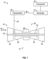
- FIG. 1 Illustrated in FIG. 1 is an embodiment of a vehicle 10, such as an aircraft.
- the aircraft includes a gas turbine engine 12 and a generator 14 operably connected to the gas turbine engine 12 to generate electrical power from rotational energy drawn from the gas turbine engine 12.
- the electrical power may be utilized, for example, to power one or more ancillary components 16 of the aircraft which are operably connected to the generator 14.
- the gas turbine engine 12 is a multi-spool gas turbine engine 12 having a low spool 18 including a low pressure compressor 20 and a low pressure turbine 22 arranged on a low spool shaft 24, and a high spool 26 including a high pressure compressor 28 and a high pressure turbine 30 arranged on a high spool shaft 32.
- airflow 34 enters the gas turbine engine 12 and flow through the low pressure compressor 20 and the high pressure compressor 28 in series to compress the airflow 34.
- the airflow 34 is mixed with fuel and combusted at a combustor 36, and the combustion products are flowed is series through the high pressure turbine 30 and the low pressure turbine 22, which drives rotation of the high pressure compressor 28 and the low pressure compressor 20, respectively.
- a transmission 40 is interposed between the gas turbine engine 12 and the generator 14 to convert rotational energy output from the gas turbine engine 12 to a speed range usable by the generator 14.
- the transmission 40 is connected to the gas turbine engine 12 via a power takeoff shaft 42, which transfers rotational energy from the gas turbine engine 12 to the transmission 40.
- the power takeoff shaft 42 is connected to the low spool shaft 24 via a takeoff gear arrangement 44.
- the transmission 40 includes an output shaft 46 that transfers rotational energy from the transmission 40 to the generator 14.
- the transmission 40 includes a control piston 48 movable along the output shaft 46 to selectably engage a clutch pack 50, which results in selection of a gear ratio to output a selected rotational speed along the output shaft 46 to the generator 14.
- the position of the control piston 48 along the output shaft 46 is controlled by fluid pressure in a control pressure chamber.
- the control piston 48 includes a piston member 54, and has a piston arm 56 engageable with the clutch pack 50.
- the control piston 48 further includes a backing plate 58 installed to the piston member 54 and also movable along the output shaft 46, which defines an enclosed volume between the piston member 54, the output shaft 46 and the backing plate 58.
- the piston member 54 includes a radially-extending piston outer wall 60, with the backing plate 58 installed to the piston member 54 radially inboard of the piston outer wall 60.
- the backing plate 58 may be retained to the piston member 54 by one or more retaining rings 62 installed into complementary ring slots 64 in the piston outer wall 60. It is to be appreciated that such a retaining mechanism is merely exemplary, and that other retaining mechanisms may be utilized to secure the backing plate 58 to the piston member 54.
- one or more seals, such as O-ring seals 66 are positioned between the backing plate 58 and the piston outer wall 60 to prevent leakage of fluid from the enclosed volume.
- the enclosed volume is separated into a control pressure chamber 68 and a pressure balancing chamber 70 by a chamber divider 72 positioned axially between a piston axial wall 74 and the backing plate 58.
- the chamber divider 72 is axially fixed relative to the output shaft 46, and in some embodiments is formed integral to the output shaft 46 as a flange extending radially outwardly from a shaft body 76 of the output shaft 46.
- the control piston 48 moves along a shaft axis 78 direction relative to the chamber divider 72 depending on the fluid pressure in each of the control pressure chamber 68 and the pressure balancing chamber 70.
- the arrangement includes glide rings 80 at the interfaces of the piston member 54 to the output shaft 46, the piston member 54 to chamber divider 72 and/or the backing plate 58 to the chamber divider 72.
- the glide rings 80 are seals which allow for relative axial movement of the components while maintaining a seal to prevent leakage.
- both the control pressure chamber 68 and the pressure balancing chamber 70 are filled with fluid, with the fluid pressure in the control pressure chamber 68 modulated via a plurality of control pressure orifices 82 through which fluid enters and exits the control pressure chamber 68.
- the fluid pressure in the pressure balancing chamber 70 is modulated via a plurality of pressure balancing orifices 84 through which fluid enters and exits the pressure balancing chamber 70.
- both the control pressure chamber 68 and the pressure balancing chamber 70 are completely filled or flooded with fluid, and the chambers spin at the same speed and are at the same temperature, they exert equal and opposite forces on the control piston 48 due to rotating oil pressure.
- the net force on the control piston 48 is only due to pressure added to or removed from the control pressure chamber 68 to effect movement of the control piston 48 between the disengaged position and the engaged position.
- This relatively small difference on pressures between the two chambers reduces the incidence of unintentional or auto engagement of the control piston 48 with the clutch pack 50 due to the rotating fluid forces.
- a return spring 86 acts on a control piston flange 88 to urge the control piston 48 toward the disengaged position.
Landscapes
- Engineering & Computer Science (AREA)
- General Engineering & Computer Science (AREA)
- Mechanical Engineering (AREA)
- Aviation & Aerospace Engineering (AREA)
- Chemical & Material Sciences (AREA)
- Combustion & Propulsion (AREA)
- Physics & Mathematics (AREA)
- Fluid Mechanics (AREA)
- Hydraulic Clutches, Magnetic Clutches, Fluid Clutches, And Fluid Joints (AREA)
Abstract
A clutch assembly includes a clutch pack (50), and a rotating control piston (48) selectably engageable with the clutch pack (50) via movement of the clutch piston along an axis of rotation of the control piston (48). The clutch piston includes a piston member (54) engageable with the clutch pack (50), a cover plate (58) installed into the piston member (54) to define an enclosed volume, and an axially fixed chamber divider (72) positioned in the enclosed volume to divide the enclosed volume into a control pressure chamber and a pressure balancing chamber. Both the control pressure chamber and the pressure balancing chamber are filled with hydraulic fluid, and the control piston (48) is moved between a disengaged position and an engaged position via modulation of hydraulic pressure in the control pressure chamber.
Description
- Exemplary embodiments pertain to the art of transmission systems, e.g. for aircraft low spool turbomachines.
- Connecting of accessory components, such as starter/generators to a low spool of a gas turbine engine requires a speed converting transmission to take a relatively wide speed range of rotational energy from the low spool and convert it to a relatively narrow speed range usable by the accessory components. One configuration for accomplishing this utilizes a shifting transmission including clutches that selectably engage different gear ratios.
- The transmission includes a rotating hydraulically actuated control piston, which is utilized to engage the gear ratios. In some conditions, the control piston is subject to inadvertently auto-actuating, in which the control piston inadvertently moves causing engagement of one or more clutches of the transmission. In typical configurations, large springs are used to prevent this auto-actuation problem, which adds weight and increases overall size of the machine.
- In one embodiment, a clutch assembly includes a clutch pack, and a rotating control piston selectably engageable with the clutch pack via movement of the clutch piston along an axis of rotation of the control piston. The clutch piston includes a piston member engageable with the clutch pack, a cover plate installed into the piston member to define an enclosed volume, and an axially fixed chamber divider positioned in the enclosed volume to divide the enclosed volume into a control pressure chamber and a pressure balancing chamber. Both the control pressure chamber and the pressure balancing chamber are filled with hydraulic fluid, and the control piston is moved between a disengaged position and an engaged position via modulation of hydraulic pressure in the control pressure chamber.
- Additionally or alternatively, in this or other embodiments the clutch assembly includes a plurality of control pressure orifices fluidly connected to the control pressure chamber through which hydraulic fluid enters and exits the control pressure chamber.
- Additionally or alternatively, in this or other embodiments the clutch assembly includes a plurality of pressure balance chamber orifices fluidly connected to the pressure balance chamber through which hydraulic fluid enters and exits the pressure balance chamber.
- Additionally or alternatively, in this or other embodiments the clutch assembly includes one or more glide rings positioned between the chamber divider and a radially outer wall of the piston member.
- Additionally or alternatively, in this or other embodiments the chamber divider is operably connected to an output shaft.
- Additionally or alternatively, in this or other embodiments the chamber divider is formed integral to the output shaft.
- Additionally or alternatively, in this or other embodiments the clutch assembly includes a retaining ring to retain the cover plate inside the piston member.
- In another embodiment, a speed changing transmission assembly includes an input shaft, an output shaft, and one or more clutch assemblies to selectably engageable with the output shaft. Each clutch assembly includes a clutch pack, and a rotating control piston selectably engageable with the clutch pack via movement of the clutch piston along an axis of rotation of the control piston. The clutch piston includes a piston member engageable with the clutch pack, a cover plate installed into the piston member to define an enclosed volume, and an axially fixed chamber divider located in the enclosed volume to divide the enclosed volume into a control pressure chamber and a pressure balancing chamber. Both the control pressure chamber and the pressure balancing chamber are filled with hydraulic fluid, and the control piston is moved between a disengaged position and an engaged position via modulation of hydraulic pressure in the control pressure chamber.
- Additionally or alternatively, in this or other embodiments the clutch assembly includes a plurality of control pressure orifices fluidly connected to the control pressure chamber through which hydraulic fluid enters and exits the control pressure chamber.
- Additionally or alternatively, in this or other embodiments the clutch assembly includes a plurality of pressure balance chamber orifices fluidly connected to the pressure balance chamber through which hydraulic fluid enters and exits the pressure balance chamber.
- Additionally or alternatively, in this or other embodiments one or more glide rings are located between the chamber divider and a radially outer wall of the piston member.
- Additionally or alternatively, in this or other embodiments the chamber divider is operably connected to the output shaft.
- Additionally or alternatively, in this or other embodiments the chamber divider is formed integral to the output shaft.
- Additionally or alternatively, in this or other embodiments the clutch assembly includes a retaining ring to retain the cover plate inside the piston member.
- In yet another embodiment, an aircraft includes a gas turbine engine and one or more accessory components operably connected to the gas turbine engine, and driven by rotational energy diverted from the gas turbine engine. A speed-changing transmission assembly is configured to convert the rotational energy diverted from the gas turbine engine to a speed range usable by the one or more accessory components. The transmission assembly includes an input shaft operably connected to the gas turbine engine, an output shaft operably connected to the one or more accessory components, and one or more clutch assemblies to selectably engageable with the output shaft. Each clutch assembly includes a clutch pack and a rotating control piston selectably engageable with the clutch pack via movement of the clutch piston along an axis of rotation of the control piston. The clutch piston includes a piston member engageable with the clutch pack, a cover plate installed into the piston member to define an enclosed volume, and an axially fixed chamber divider positioned in the enclosed volume to divide the enclosed volume into a control pressure chamber and a pressure balancing chamber. Both the control pressure chamber and the pressure balancing chamber are filled with hydraulic fluid, and the control piston is moved between a disengaged position and an engaged position via modulation of hydraulic pressure in the control pressure chamber.
- Additionally or alternatively, in this or other embodiments each clutch assembly includes a plurality of control pressure orifices fluidly connected to the control pressure chamber through which hydraulic fluid enters and exits the control pressure chamber.
- Additionally or alternatively, in this or other embodiments each clutch assembly includes a plurality of pressure balance chamber orifices fluidly connected to the pressure balance chamber through which hydraulic fluid enters and exits the pressure balance chamber.
- Additionally or alternatively, in this or other embodiments the chamber divider is operably connected to the output shaft.
- Additionally or alternatively, in this or other embodiments the input shaft diverts the rotational energy from a low speed spool of the gas turbine engine.
- Additionally or alternatively, in this or other embodiments the one or more accessory components includes a generator.
- The following descriptions should not be considered limiting in any way. With reference to the accompanying drawings, like elements are numbered alike:
-
FIG. 1 is a schematic illustration of an embodiment of a vehicle; -
FIG. 2 is a partial illustration of an embodiment of a power takeoff arrangement of a gas turbine engine; and -
FIG. 3 is a partial cross-sectional view of an embodiment of a transmission. - A detailed description of one or more embodiments of the disclosed apparatus and method are presented herein by way of exemplification and not limitation with reference to the Figures.
- Illustrated in
FIG. 1 is an embodiment of avehicle 10, such as an aircraft. The aircraft includes agas turbine engine 12 and agenerator 14 operably connected to thegas turbine engine 12 to generate electrical power from rotational energy drawn from thegas turbine engine 12. The electrical power may be utilized, for example, to power one or moreancillary components 16 of the aircraft which are operably connected to thegenerator 14. - In some embodiments the
gas turbine engine 12 is a multi-spoolgas turbine engine 12 having alow spool 18 including alow pressure compressor 20 and alow pressure turbine 22 arranged on alow spool shaft 24, and ahigh spool 26 including ahigh pressure compressor 28 and ahigh pressure turbine 30 arranged on ahigh spool shaft 32. In operation,airflow 34 enters thegas turbine engine 12 and flow through thelow pressure compressor 20 and thehigh pressure compressor 28 in series to compress theairflow 34. Theairflow 34 is mixed with fuel and combusted at acombustor 36, and the combustion products are flowed is series through thehigh pressure turbine 30 and thelow pressure turbine 22, which drives rotation of thehigh pressure compressor 28 and thelow pressure compressor 20, respectively. - A
transmission 40 is interposed between thegas turbine engine 12 and thegenerator 14 to convert rotational energy output from thegas turbine engine 12 to a speed range usable by thegenerator 14. Thetransmission 40 is connected to thegas turbine engine 12 via apower takeoff shaft 42, which transfers rotational energy from thegas turbine engine 12 to thetransmission 40. In some embodiments, referring toFIG. 2 , thepower takeoff shaft 42 is connected to thelow spool shaft 24 via atakeoff gear arrangement 44. Referring again toFIG. 1 , thetransmission 40 includes anoutput shaft 46 that transfers rotational energy from thetransmission 40 to thegenerator 14. - Illustrated in
FIG. 3 is a partial cross-sectional view of thetransmission 40. Thetransmission 40 includes acontrol piston 48 movable along theoutput shaft 46 to selectably engage aclutch pack 50, which results in selection of a gear ratio to output a selected rotational speed along theoutput shaft 46 to thegenerator 14. The position of thecontrol piston 48 along theoutput shaft 46 is controlled by fluid pressure in a control pressure chamber. Thecontrol piston 48 includes apiston member 54, and has apiston arm 56 engageable with theclutch pack 50. Thecontrol piston 48 further includes abacking plate 58 installed to thepiston member 54 and also movable along theoutput shaft 46, which defines an enclosed volume between thepiston member 54, theoutput shaft 46 and thebacking plate 58. In some embodiments, thepiston member 54 includes a radially-extending pistonouter wall 60, with thebacking plate 58 installed to thepiston member 54 radially inboard of the pistonouter wall 60. Thebacking plate 58 may be retained to thepiston member 54 by one ormore retaining rings 62 installed intocomplementary ring slots 64 in the pistonouter wall 60. It is to be appreciated that such a retaining mechanism is merely exemplary, and that other retaining mechanisms may be utilized to secure thebacking plate 58 to thepiston member 54. In some embodiments, one or more seals, such as O-ring seals 66 are positioned between thebacking plate 58 and the pistonouter wall 60 to prevent leakage of fluid from the enclosed volume. - The enclosed volume is separated into a
control pressure chamber 68 and apressure balancing chamber 70 by achamber divider 72 positioned axially between a pistonaxial wall 74 and thebacking plate 58. Thechamber divider 72 is axially fixed relative to theoutput shaft 46, and in some embodiments is formed integral to theoutput shaft 46 as a flange extending radially outwardly from ashaft body 76 of theoutput shaft 46. In such an arrangement, thecontrol piston 48 moves along ashaft axis 78 direction relative to thechamber divider 72 depending on the fluid pressure in each of thecontrol pressure chamber 68 and thepressure balancing chamber 70. In some embodiments, the arrangement includes glide rings 80 at the interfaces of thepiston member 54 to theoutput shaft 46, thepiston member 54 tochamber divider 72 and/or thebacking plate 58 to thechamber divider 72. The glide rings 80 are seals which allow for relative axial movement of the components while maintaining a seal to prevent leakage. - To modulate the position of the
control piston 48 relative to theclutch pack 50 between a disengaged position illustrated inFIG. 3 , and an engaged position, the fluid pressure in thecontrol pressure chamber 68 is varied. To move thecontrol piston 48 to the engaged position, the fluid pressure in thecontrol pressure chamber 68 is increased to urge thecontrol piston 48 into engagement with theclutch pack 50. In some conditions, such as high speed rotation, thecontrol piston 48 must be prevented from auto-actuating due to excess pressure in thecontrol pressure chamber 68 from the rotation. To counteract this tendency, both thecontrol pressure chamber 68 and thepressure balancing chamber 70 are filled with fluid, with the fluid pressure in thecontrol pressure chamber 68 modulated via a plurality ofcontrol pressure orifices 82 through which fluid enters and exits thecontrol pressure chamber 68. Similarly, the fluid pressure in thepressure balancing chamber 70 is modulated via a plurality ofpressure balancing orifices 84 through which fluid enters and exits thepressure balancing chamber 70. - Because both the
control pressure chamber 68 and thepressure balancing chamber 70 are completely filled or flooded with fluid, and the chambers spin at the same speed and are at the same temperature, they exert equal and opposite forces on thecontrol piston 48 due to rotating oil pressure. The net force on thecontrol piston 48 is only due to pressure added to or removed from thecontrol pressure chamber 68 to effect movement of thecontrol piston 48 between the disengaged position and the engaged position. This relatively small difference on pressures between the two chambers reduces the incidence of unintentional or auto engagement of thecontrol piston 48 with theclutch pack 50 due to the rotating fluid forces. In operating conditions where no control pressure is applied, areturn spring 86 acts on acontrol piston flange 88 to urge thecontrol piston 48 toward the disengaged position. - The term "about" is intended to include the degree of error associated with measurement of the particular quantity based upon the equipment available at the time of filing the application.
- The terminology used herein is for the purpose of describing particular embodiments only and is not intended to be limiting of the present disclosure. As used herein, the singular forms "a", "an" and "the" are intended to include the plural forms as well, unless the context clearly indicates otherwise. It will be further understood that the terms "comprises" and/or "comprising," when used in this specification, specify the presence of stated features, integers, steps, operations, elements, and/or components, but do not preclude the presence or addition of one or more other features, integers, steps, operations, element components, and/or groups thereof.
- While the present disclosure has been described with reference to an exemplary embodiment or embodiments, it will be understood by those skilled in the art that various changes may be made and equivalents may be substituted for elements thereof without departing from the scope of the present disclosure. In addition, many modifications may be made to adapt a particular situation or material to the teachings of the present disclosure without departing from the essential scope thereof. Therefore, it is intended that the present disclosure not be limited to the particular embodiment disclosed as the best mode contemplated for carrying out this present disclosure, but that the present disclosure will include all embodiments falling within the scope of the claims.
Claims (15)
- A clutch assembly, comprising:a clutch pack (50);a rotating control piston (48) selectably engageable with the clutch pack (50) via movement of the clutch piston along an axis of rotation of the control piston (48), the clutch piston including:a piston member (54) engageable with the clutch pack (50);a cover plate installed into the piston member (54) to define an enclosed volume;an axially fixed chamber divider disposed in the enclosed volume to divide the enclosed volume into a control pressure chamber and a pressure balancing chamber;wherein both the control pressure chamber and the pressure balancing chamber are filled with hydraulic fluid; andwherein the control piston (48) is moved between a disengaged position and an engaged position via modulation of hydraulic pressure in the control pressure chamber.
- The clutch assembly of claim 1, further comprising a plurality of control pressure orifices fluidly connected to the control pressure chamber through which hydraulic fluid enters and exits the control pressure chamber.
- The clutch assembly of any preceding claim, further comprising a plurality of pressure balance chamber orifices fluidly connected to the pressure balance chamber through which hydraulic fluid enters and exits the pressure balance chamber.
- The clutch assembly of any preceding claim, further comprising one or more glide rings between the chamber divider and a radially outer wall of the piston member (54).
- The clutch assembly of any preceding claim, wherein the chamber divider is operably connected to an output shaft, and optionally wherein the chamber divider is formed integral to the output shaft.
- The clutch assembly of any preceding claim, further comprising a retaining ring to retain the cover plate inside the piston member (54).
- A speed changing transmission assembly, comprising:
an input shaft:an output shaft; andone or more clutch assemblies to selectably engageable with the output shaft, each clutch assembly including:a clutch pack (50);a rotating control piston (48) selectably engageable with the clutch pack (50) via movement of the clutch piston along an axis of rotation of the control piston (48), the clutch piston including:a piston member (54) engageable with the clutch pack (50);a cover plate installed into the piston member (54) to define an enclosed volume;an axially fixed chamber divider disposed in the enclosed volume to divide the enclosed volume into a control pressure chamber and a pressure balancing chamber;wherein both the control pressure chamber and the pressure balancing chamber are filled with hydraulic fluid; andwherein the control piston (48) is moved between a disengaged position and an engaged position via modulation of hydraulic pressure in the control pressure chamber. - The transmission assembly of claim 7, further comprising a plurality of control pressure orifices fluidly connected to the control pressure chamber through which hydraulic fluid enters and exits the control pressure chamber, and/or further comprising a plurality of pressure balance chamber orifices fluidly connected to the pressure balance chamber through which hydraulic fluid enters and exits the pressure balance chamber, and/or further comprising one or more glide rings disposed between the chamber divider and a radially outer wall of the piston member (54).
- The transmission assembly of claim 7 or 8, wherein the chamber divider is operably connected to the output shaft, and optionally wherein the chamber divider is formed integral to the output shaft.
- The transmission assembly of any of claims 7 to 9, further comprising a retaining ring to retain the cover plate inside the piston member (54).
- An aircraft, comprising:a gas turbine engine;one or more accessory components operably connected to the gas turbine engine, and driven by rotational energy diverted from the gas turbine engine;a speed-changing transmission assembly configured to convert the rotational energy diverted from the gas turbine engine to a speed range usable by the one or more accessory components, the transmission assembly including:
an input shaft operably connected to the gas turbine engine:an output shaft operably connected to the one or more accessory components; andone or more clutch assemblies to selectably engageable with the output shaft, each clutch assembly including:a clutch pack (50);a rotating control piston (48) selectably engageable with the clutch pack (50) via movement of the clutch piston along an axis of rotation of the control piston (48), the clutch piston including:a piston member (54) engageable with the clutch pack (50);a cover plate installed into the piston member (54) to define an enclosed volume;an axially fixed chamber divider disposed in the enclosed volume to divide the enclosed volume into a control pressure chamber and a pressure balancing chamber;wherein both the control pressure chamber and the pressure balancing chamber are filled with hydraulic fluid; andwherein the control piston (48) is moved between a disengaged position and an engaged position via modulation of hydraulic pressure in the control pressure chamber. - The aircraft of claim 11, further comprising a plurality of control pressure orifices fluidly connected to the control pressure chamber through which hydraulic fluid enters and exits the control pressure chamber.
- The aircraft of claim 11 or 12, further comprising a plurality of pressure balance chamber orifices fluidly connected to the pressure balance chamber through which hydraulic fluid enters and exits the pressure balance chamber.
- The aircraft of claim 11, 12 or 13, wherein the chamber divider is operably connected to the output shaft.
- The aircraft of claim 11, 12, 13 or 14, wherein the input shaft diverts the rotational energy from a low speed spool of the gas turbine engine, and/or wherein the one or more accessory components includes a generator.
Applications Claiming Priority (1)
| Application Number | Priority Date | Filing Date | Title |
|---|---|---|---|
| US18/295,587 US12000343B1 (en) | 2023-04-04 | 2023-04-04 | Pressure balancing of rotating control piston of generator transmission |
Publications (1)
| Publication Number | Publication Date |
|---|---|
| EP4471286A1 true EP4471286A1 (en) | 2024-12-04 |
Family
ID=90717434
Family Applications (1)
| Application Number | Title | Priority Date | Filing Date |
|---|---|---|---|
| EP24168218.6A Pending EP4471286A1 (en) | 2023-04-04 | 2024-04-03 | Pressure balancing of rotating control piston of generator transmission |
Country Status (2)
| Country | Link |
|---|---|
| US (1) | US12000343B1 (en) |
| EP (1) | EP4471286A1 (en) |
Citations (2)
| Publication number | Priority date | Publication date | Assignee | Title |
|---|---|---|---|---|
| US5495927A (en) * | 1994-06-24 | 1996-03-05 | General Motors Corporation | Controlled cooling apparatus for torque transfer devices |
| EP3726083A1 (en) * | 2019-04-18 | 2020-10-21 | Hamilton Sundstrand Corporation | Wet clutch assemblies |
Family Cites Families (5)
| Publication number | Priority date | Publication date | Assignee | Title |
|---|---|---|---|---|
| US3403763A (en) * | 1967-01-16 | 1968-10-01 | Twin Disc Inc | Power transmitting device having hydraulically actuated friction plates and torque sensing means |
| US3823802A (en) * | 1972-08-18 | 1974-07-16 | Caterpillar Tractor Co | Clutch with controlled coolant flow |
| DE102004007153B3 (en) * | 2004-02-12 | 2005-11-03 | Ortlinghaus-Werke Gmbh | Fluidically actuated rotary drive clutch |
| WO2011024928A1 (en) | 2009-08-24 | 2011-03-03 | Kawanishi Eiji | Hybrid power generator coupled to gravity power generator using balance which has pressure load device |
| US11226014B2 (en) | 2019-04-18 | 2022-01-18 | Hamilton Sundstrand Corporation | Hydraulic clutch assemblies |
-
2023
- 2023-04-04 US US18/295,587 patent/US12000343B1/en active Active
-
2024
- 2024-04-03 EP EP24168218.6A patent/EP4471286A1/en active Pending
Patent Citations (2)
| Publication number | Priority date | Publication date | Assignee | Title |
|---|---|---|---|---|
| US5495927A (en) * | 1994-06-24 | 1996-03-05 | General Motors Corporation | Controlled cooling apparatus for torque transfer devices |
| EP3726083A1 (en) * | 2019-04-18 | 2020-10-21 | Hamilton Sundstrand Corporation | Wet clutch assemblies |
Also Published As
| Publication number | Publication date |
|---|---|
| US12000343B1 (en) | 2024-06-04 |
Similar Documents
| Publication | Publication Date | Title |
|---|---|---|
| US4018316A (en) | Engine and transmission power train | |
| KR100254928B1 (en) | Clutch assembly for an automatic mechanical transmission | |
| US8240441B2 (en) | Hydrodynamic coupling device for hybrid vehicles | |
| EP0282169B1 (en) | Clutch assembly with a pressure-balance chamber | |
| US4289048A (en) | Lock-up system for torque converter | |
| US7287634B2 (en) | Torque transmitting unit and drive train for it | |
| US10066741B2 (en) | Transmission and hydraulic control system | |
| US9217498B2 (en) | Multi-function torque converter with a sealed impeller clutch apply chamber and method of forming and operating a multi-function torque converter | |
| US4951788A (en) | Torque converter multiplate bypass clutch | |
| US6003647A (en) | Torque converter with lock-up clutch having a flow-restraining elastic friction member | |
| HU176676B (en) | Hydrodynamic torque converter drive | |
| EP4166806B1 (en) | A porting manifold | |
| WO2021231202A1 (en) | Hybrid module with sequential clutch | |
| EP3385557B1 (en) | Clutch device for gas turbine engine | |
| CA1095844A (en) | Clutch with coolant flow control means | |
| US4982826A (en) | Bleeder ball check valves in an automatic transmission | |
| US3833100A (en) | Control system for a power transmission clutch | |
| CN111425578B (en) | Torque converter assembly and method of operating the same | |
| EP4471286A1 (en) | Pressure balancing of rotating control piston of generator transmission | |
| US3598211A (en) | Speed-responsive clutch | |
| EP0660010B1 (en) | A vehicular drivetrain | |
| US2564466A (en) | Transmission mechanism | |
| US4958753A (en) | Clutch reaction and pressure plates in an automatic transmission | |
| EP0095258A2 (en) | Centrifugally responsive hydraulically applied friction clutch | |
| US12480596B2 (en) | Multi-function fluid control valve |
Legal Events
| Date | Code | Title | Description |
|---|---|---|---|
| PUAI | Public reference made under article 153(3) epc to a published international application that has entered the european phase |
Free format text: ORIGINAL CODE: 0009012 |
|
| STAA | Information on the status of an ep patent application or granted ep patent |
Free format text: STATUS: THE APPLICATION HAS BEEN PUBLISHED |
|
| AK | Designated contracting states |
Kind code of ref document: A1 Designated state(s): AL AT BE BG CH CY CZ DE DK EE ES FI FR GB GR HR HU IE IS IT LI LT LU LV MC ME MK MT NL NO PL PT RO RS SE SI SK SM TR |
|
| STAA | Information on the status of an ep patent application or granted ep patent |
Free format text: STATUS: REQUEST FOR EXAMINATION WAS MADE |
|
| 17P | Request for examination filed |
Effective date: 20250604 |