EP4471283A1 - Rotating mechanism and electronic device - Google Patents
Rotating mechanism and electronic device Download PDFInfo
- Publication number
- EP4471283A1 EP4471283A1 EP23867291.9A EP23867291A EP4471283A1 EP 4471283 A1 EP4471283 A1 EP 4471283A1 EP 23867291 A EP23867291 A EP 23867291A EP 4471283 A1 EP4471283 A1 EP 4471283A1
- Authority
- EP
- European Patent Office
- Prior art keywords
- swing arm
- bracket
- sliding
- rotating groove
- rotating
- Prior art date
- Legal status (The legal status is an assumption and is not a legal conclusion. Google has not performed a legal analysis and makes no representation as to the accuracy of the status listed.)
- Pending
Links
Images





Classifications
-
- G—PHYSICS
- G06—COMPUTING OR CALCULATING; COUNTING
- G06F—ELECTRIC DIGITAL DATA PROCESSING
- G06F1/00—Details not covered by groups G06F3/00 - G06F13/00 and G06F21/00
- G06F1/16—Constructional details or arrangements
- G06F1/1613—Constructional details or arrangements for portable computers
- G06F1/1633—Constructional details or arrangements of portable computers not specific to the type of enclosures covered by groups G06F1/1615 - G06F1/1626
- G06F1/1675—Miscellaneous details related to the relative movement between the different enclosures or enclosure parts
- G06F1/1681—Details related solely to hinges
-
- H—ELECTRICITY
- H05—ELECTRIC TECHNIQUES NOT OTHERWISE PROVIDED FOR
- H05K—PRINTED CIRCUITS; CASINGS OR CONSTRUCTIONAL DETAILS OF ELECTRIC APPARATUS; MANUFACTURE OF ASSEMBLAGES OF ELECTRICAL COMPONENTS
- H05K5/00—Casings, cabinets or drawers for electric apparatus
- H05K5/02—Details
- H05K5/0217—Mechanical details of casings
- H05K5/0226—Hinges
-
- G—PHYSICS
- G06—COMPUTING OR CALCULATING; COUNTING
- G06F—ELECTRIC DIGITAL DATA PROCESSING
- G06F1/00—Details not covered by groups G06F3/00 - G06F13/00 and G06F21/00
- G06F1/16—Constructional details or arrangements
- G06F1/1613—Constructional details or arrangements for portable computers
- G06F1/1615—Constructional details or arrangements for portable computers with several enclosures having relative motions, each enclosure supporting at least one I/O or computing function
- G06F1/1616—Constructional details or arrangements for portable computers with several enclosures having relative motions, each enclosure supporting at least one I/O or computing function with folding flat displays, e.g. laptop computers or notebooks having a clamshell configuration, with body parts pivoting to an open position around an axis parallel to the plane they define in closed position
-
- G—PHYSICS
- G06—COMPUTING OR CALCULATING; COUNTING
- G06F—ELECTRIC DIGITAL DATA PROCESSING
- G06F1/00—Details not covered by groups G06F3/00 - G06F13/00 and G06F21/00
- G06F1/16—Constructional details or arrangements
- G06F1/1613—Constructional details or arrangements for portable computers
- G06F1/1615—Constructional details or arrangements for portable computers with several enclosures having relative motions, each enclosure supporting at least one I/O or computing function
- G06F1/1624—Constructional details or arrangements for portable computers with several enclosures having relative motions, each enclosure supporting at least one I/O or computing function with sliding enclosures, e.g. sliding keyboard or display
-
- G—PHYSICS
- G06—COMPUTING OR CALCULATING; COUNTING
- G06F—ELECTRIC DIGITAL DATA PROCESSING
- G06F1/00—Details not covered by groups G06F3/00 - G06F13/00 and G06F21/00
- G06F1/16—Constructional details or arrangements
- G06F1/1613—Constructional details or arrangements for portable computers
- G06F1/1633—Constructional details or arrangements of portable computers not specific to the type of enclosures covered by groups G06F1/1615 - G06F1/1626
- G06F1/1637—Details related to the display arrangement, including those related to the mounting of the display in the housing
- G06F1/1652—Details related to the display arrangement, including those related to the mounting of the display in the housing the display being flexible, e.g. mimicking a sheet of paper, or rollable
-
- H—ELECTRICITY
- H04—ELECTRIC COMMUNICATION TECHNIQUE
- H04M—TELEPHONIC COMMUNICATION
- H04M1/00—Substation equipment, e.g. for use by subscribers
- H04M1/02—Constructional features of telephone sets
- H04M1/0202—Portable telephone sets, e.g. cordless phones, mobile phones or bar type handsets
- H04M1/0206—Portable telephones comprising a plurality of mechanically joined movable body parts, e.g. hinged housings
- H04M1/0208—Portable telephones comprising a plurality of mechanically joined movable body parts, e.g. hinged housings characterized by the relative motions of the body parts
- H04M1/0214—Foldable telephones, i.e. with body parts pivoting to an open position around an axis parallel to the plane they define in closed position
- H04M1/0216—Foldable in one direction, i.e. using a one degree of freedom hinge
- H04M1/022—The hinge comprising two parallel pivoting axes
-
- H—ELECTRICITY
- H04—ELECTRIC COMMUNICATION TECHNIQUE
- H04M—TELEPHONIC COMMUNICATION
- H04M1/00—Substation equipment, e.g. for use by subscribers
- H04M1/02—Constructional features of telephone sets
- H04M1/0202—Portable telephone sets, e.g. cordless phones, mobile phones or bar type handsets
- H04M1/0206—Portable telephones comprising a plurality of mechanically joined movable body parts, e.g. hinged housings
- H04M1/0208—Portable telephones comprising a plurality of mechanically joined movable body parts, e.g. hinged housings characterized by the relative motions of the body parts
- H04M1/0235—Slidable or telescopic telephones, i.e. with a relative translation movement of the body parts; Telephones using a combination of translation and other relative motions of the body parts
Definitions
- This application relates to the field of electronic product technologies, and in particular, to a rotating mechanism and an electronic device.
- the foldable terminal product (such as a foldable mobile phone, a foldable tablet, or a foldable computer) needs to satisfy a good appearance form and good experience, to be accepted by a consumer.
- the foldable terminal product often implements a rotating movement by using a swing arm mounted on a shaft cover bracket.
- existing arrangement of a structure of a sliding groove of the swing arm easily affects a thickness of the entire machine.
- Embodiments of this application provide a rotating mechanism and an electronic device. Arrangement of a structure of the rotating mechanism is conductive to reducing a thickness of an entire machine on a basis of ensuring a rotating movement of a swing arm.
- this application provides a rotating mechanism.
- the rotating mechanism includes a bracket, a first main swing arm, and a second main swing arm.
- a first rotating groove and a second rotating groove are disposed on the bracket.
- the first rotating groove and the second rotating groove are distributed on two opposite sides of the bracket.
- the first rotating groove includes a first sliding rail and two second sliding rails.
- the two second sliding rails are respectively located on two opposite sides of the first sliding rail, and are disposed side by side with the first sliding rail in a length direction of the bracket.
- the first main swing arm is mounted in the first rotating groove.
- the first main swing arm can slide on the first sliding rail and the two second sliding rails.
- the first main swing arm can rotate relative to the bracket.
- the second rotating groove includes a third sliding rail and two fourth sliding rails.
- the two fourth sliding rails are respectively located on two opposite sides of the third sliding rail, and are disposed side by side with the third sliding rail in the length direction of the bracket.
- the second main swing arm is mounted in the second rotating groove.
- the second main swing arm can slide on the third sliding rail and the two fourth sliding rails.
- the second main swing arm can rotate relative to the bracket.
- a rotation direction of the second main swing arm is opposite to that of the first main swing arm.
- the first sliding rail and the second sliding rail enable the swing arms to slide thereon.
- a rotating movement of the swing arms and the bracket can be implemented.
- the first rotating groove (a sliding groove of the swing arm) is disposed on the bracket, so that space on the bracket can be fully utilized to properly arrange a structure of the first rotating groove.
- the swing arm occupies small space in a folded state, to help implement lightening and thinning of an entire machine.
- first sliding rail and the two second sliding rails are disposed in the first rotating groove, so that a sliding trajectory of the swing arm is jointly limited by the first sliding rail and the two second sliding rails.
- the sliding trajectory of the swing arm is jointly limited by the first sliding rail and the two second sliding rails, so that a precision requirement on the first rotating groove can be reduced, thereby reducing machining difficulty and machining costs of the bracket.
- the sliding trajectory of the swing arm is jointly limited by the first sliding rail and the two second sliding rails, so that the first sliding rail and the two second sliding rails are arranged in a distributed manner.
- the plurality of sliding rails arranged in the distributed manner can increase strength of the first rotating groove, so that the swing arm is not easily deformed and stuck when the swing arm slides on the sliding rails, and reliability is good.
- the first main swing arm includes a first sliding portion and two second sliding portions.
- the two second sliding portions are connected to two opposite sides of the first sliding portion.
- the first sliding portion is mounted on the first sliding rail.
- Each second sliding portion is mounted on one second sliding rail.
- a structure of a first rotating body can match the structure of the first rotating groove of the bracket, a structure of the first sliding portion can match a structure of the first sliding rail, and a structure of the second sliding portion can match a structure of the second sliding rail, to facilitate a smooth rotating movement of the first main swing arm relative to the bracket.
- the first sliding portion and the two second sliding portions cooperate to form a first concave area.
- the first sliding rail is partially located in the first concave area.
- the first sliding portion is concave inward relative to the two second sliding portions.
- the first concave area formed by the first sliding portion being concave inward relative to the two second sliding portions can provide space to accommodate the first sliding rail, to help improve space utilization of the rotating mechanism in a limited space layout, and reliability is good.
- the first sliding rail includes two first convex portions disposed opposite to each other.
- a surface that is of each first convex portion and that is away from a bottom wall of the first rotating groove is in contact with the first sliding portion.
- Each first convex portion includes a first end and a second end, and the first end is disposed closer to an edge of the bracket in comparison with the second end.
- a height of a cross section that is of each first convex portion and that is in a direction perpendicular to the bottom wall of the first rotating groove gradually decreases from the first end to the second end.
- the rotating mechanism further includes a base.
- the bracket is fixed to the base.
- a mounting column is disposed on the base.
- the first sliding rail further includes a first connecting portion.
- the first connecting portion is connected between the first ends of the two first convex portions.
- the first connecting portion and the two first convex portions cooperate to enclose mounting space.
- a mounting hole is disposed on the bracket.
- the mounting hole is located between the two first convex portions and disposed close to the first connecting portion.
- the mounting column passes through the mounting hole.
- the mounting column is located in the mounting space.
- each first sliding rail includes a first bump and a first rail structure.
- the first bump is connected to a side wall of the first rotating groove.
- the first rail structure is connected to the bottom wall of the first rotating groove.
- the first bump and the first rail structure are disposed at intervals.
- the second sliding portion is located in a gap area between the first bump and the first rail structure.
- the first bump is disposed on the side wall of the first rotating groove, so that the swing arm mounted in the first rotating groove can be limited, to help avoid a case that the swing arm mounted in the first rotating groove leaves the first rotating groove.
- the first rail structure may be curved.
- a first hollowed-out portion is disposed on the first rail structure.
- the first hollowed-out portion is disposed opposite to the first bump.
- the first hollowed-out portion penetrates the bottom wall of the first rotating groove.
- the arrangement of the first hollowed-out portion can enable the bracket to be made through mold shaping, thereby simplifying a machining process of the bracket, to help reduce production costs and improve production efficiency.
- the first rotating groove and the second rotating groove are of an integrated structure.
- the rotating mechanism further includes the base.
- the bracket is fixed to the base. Orthographic projections that are of the first rotating groove and the second rotating groove and that are on the base entirely fall on the base.
- the bracket is enabled to match arrangement of the structures of the first rotating groove and the second rotating groove, and the bracket is also located in a space range defined by the base, so that a size of the bracket can match a size of the base, and the bracket do not protrude relative to the base.
- the first rotating groove and the second rotating groove do not protrude relative to the base.
- this application further provides an electronic device.
- the electronic device includes a first housing, a second housing, and the foregoing rotating mechanism.
- the rotating mechanism is connected between the first housing and the second housing.
- a term "and/or" describes only an association relationship for describing associated objects and represents that three relationships may exist.
- a and/or B may represent the following three cases: only A exists, both A and B exist, and only B exists.
- a term "a plurality of” refers to two or more.
- connection should be understood in a broad sense.
- a connection between A and B may be a direct connection between A and B, or an indirect connection between A and B by using an intermediary.
- Embodiments of this application provide a rotating mechanism and an electronic device using the rotating mechanism.
- Arrangement of a structure of the rotating mechanism is conductive to reducing a thickness of an entire machine on a basis of ensuring a rotating movement of a swing arm.
- the electronic device may be any device with foldable performance, and can be unfolded and folded through an operation of a user.
- the electronic device includes but is not limited to a mobile phone (cellphone), a notebook computer (notebook computer), a tablet personal computer (tablet personal computer), a laptop computer (laptop computer), a personal digital assistant (personal digital assistant), a wearable device (wearable device), a vehicle-mounted device (mobile device), or the like.
- a mobile phone cellphone
- notebook computer notebook computer
- tablet personal computer tablet personal computer
- laptop computer laptop computer
- personal digital assistant personal digital assistant
- wearable device wearable device
- vehicle-mounted device mobile device
- FIG. 1 is a simplified schematic diagram of a structure of an electronic device 400 in a folded state according to an embodiment of this application.
- FIG. 2 is a simplified schematic diagram of a structure of the electronic device 400 shown in FIG. 1 in an intermediate state.
- FIG. 3 is a simplified schematic diagram of a structure of the electronic device 400 shown in FIG. 1 in an unfolded state.
- An unfolding angle ⁇ of the electronic device 400 shown in FIG. 2 is 120 degrees
- an unfolding angle ⁇ of the electronic device 400 shown in FIG. 3 is 180 degrees.
- a length direction of the electronic device 400 is defined as a direction X
- a width direction of the electronic device 400 is defined as a direction Y
- a thickness direction of the electronic device 400 is defined as a direction Z.
- the direction X, the direction Y, and the direction Z are perpendicular to each other.
- the angle illustrated in this embodiment of this application is allowed to have a slight deviation.
- the unfolding angle ⁇ of the electronic device 400 shown in FIG. 2 is 120 degrees means that ⁇ may be 120 degrees or approximately 120 degrees, such as 110 degrees, 115 degrees, 125 degrees, or 130 degrees.
- That the unfolding angle ⁇ of the electronic device 400 shown in FIG. 3 is 180 degrees means that ⁇ may be 180 degrees or approximately 180 degrees, such as 0 degrees, 5 degrees, 185 degrees, or 190 degrees.
- An angle used as an example for description in the following specification may be understood in a same way.
- the electronic device 400 shown in this embodiment of this application is an electronic device that can be folded once.
- the electronic device 400 may alternatively be an electronic device that can be folded for a plurality of times (at least twice).
- the electronic device 400 may include a plurality of parts. Two adjacent parts may be folded relatively close to each other until the electronic device 400 is in a folded state, and the two adjacent parts may be unfolded relatively away from each other until the electronic device 400 is in an unfolded state.
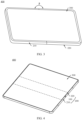
- FIG. 4 is a schematic diagram of a structure of an electronic device 400 according to an embodiment of this application.
- FIG. 5 is a schematic exploded view of the electronic device 400 shown in FIG. 4 .
- the electronic device 400 includes a foldable apparatus 200 and a flexible display screen 300.
- the flexible display screen 300 is mounted on the foldable apparatus 200.
- the flexible display screen 300 includes a first part 310, a second part 320, and a foldable part 330.
- the foldable part 330 is located between the first part 310 and the second part 320, and the foldable part 330 may be bent.
- the first part 310, the second part 320, and the foldable part 330 jointly constitute the flexible display screen 300.
- the flexible display screen 300 may be an organic light-emitting diode (organic light-emitting diode, OLED) display, an active-matrix organic light-emitting diode (active-matrix organic light-emitting diode, AMOLED) display, a mini light-emitting diode (mini organic lightemitting diode) display, a micro light-emitting diode (micro organic light-emitting diode) display, a micro organic light-emitting diode (micro organic light-emitting diode) display, or a quantum dot light-emitting diode (quantum dot light emitting diodes, QLED) display.
- OLED organic light-emitting diode
- AMOLED active-matrix organic light-emitting diode
- mini light-emitting diode mini organic lightemitting diode
- micro light-emitting diode micro organic light-emitting diode
- the foldable apparatus 200 includes a first housing 210, a second housing 220, and a rotating mechanism 100.
- a first accommodating groove 230 is disposed on the first housing 210.
- a second accommodating groove 240 is disposed on the second housing 220.
- the first accommodating groove 230 is in communication with the second accommodating groove 240 to form an accommodating groove.
- the rotating mechanism 100 is mounted in the accommodating groove and fixedly connected to the first housing 210 and the second housing 220, to achieve a rotating connection between the first housing 210 and the second housing 220.
- the first housing 210 and the second housing 220 may rotate relative to each other through the rotating mechanism 100, so that the foldable apparatus 200 switches between the folded state and the unfolded state.
- Accommodating space (not shown in the figure) is further disposed between the first housing 210 and the second housing 220.
- the accommodating space is for accommodating an electronic element, such as a processor, a circuit board, or a camera module, and a structural element of the electronic device 400.
- that the relative rotation of the first housing 210 and the second housing 220 enables the foldable apparatus 200 to be in the folded state means that the first housing 210 and the second housing 220 rotate through the rotating mechanism 100 and approach each other. Surfaces that are of the first housing 210 and the second housing 220 and that carry the flexible display screen 300 are opposite to each other.
- the first part 310 and the second part 320 are stacked and partially in contact, or certainly, may be fully in contact.
- that the relative rotation of the first housing 210 and the second housing 220 enables the foldable apparatus 200 to be in an intermediate state means that the first housing 210 and the second housing 220 rotate through the rotating mechanism 100 and move away from each other, and an included angle between the first housing 210 and the second housing 220 becomes larger.
- that the relative rotation of the first housing 210 and the second housing 220 enables the foldable apparatus 200 to be in an unfolded state means that the first housing 210 and the second housing 220 rotate through the rotating mechanism 100 and move away from each other, and the included angle between the first housing 210 and the second housing 220 continues to increase, and may be close to 180 degrees or equal to 180 degrees.
- the flexible display screen 300 is connected to the foldable apparatus 200.
- the first housing 210 carries the first part 310 of the flexible display screen 300
- the second housing 220 carries the second part 320 of the flexible display screen 300
- the foldable part 330 of the flexible display screen 300 is disposed opposite to the rotating mechanism 100.
- the first housing 210 and the second housing 220 rotate relative to each other through the rotating mechanism 100.
- the first housing 210 and the second housing 220 relatively approach each other to drive the flexible display screen 300 to be folded, so that electronic device 400 is folded.
- the foldable part 330 of the flexible display screen 300 is bent, and the first part 310 is disposed opposite to the second part 320.
- the flexible display screen 300 is located between the first housing 210 and the second housing 220, so that a probability of damaging the flexible display screen 300 can be greatly reduced, and the flexible display screen 300 is effectively protected.
- the first housing 210 and the second housing 220 rotate relative to each other through the rotating mechanism 100.
- the first housing 210 and the second housing 220 relatively move away from each other to drive the flexible display screen 300 to be unfolded, so that electronic device 400 is unfolded to the intermediate state.
- the first housing 210 and the second housing 220 are unfolded to have an included angle ⁇ .
- the first part 310 and the second part 320 are unfolded relative to each other, and drive the foldable part 330 to be unfolded.
- the included angle between the first part 310 and the second part 320 is ⁇ .
- ⁇ is 120 degrees.
- ⁇ may alternatively be approximately 120 degrees, such as 110 degrees, 115 degrees, 125 degrees, or 130 degrees.
- the first housing 210 and the second housing 220 rotate relative to each other through the rotating mechanism 100.
- the first housing 210 and the second housing 220 relatively move away from each other to drive the flexible display screen 300 to be further unfolded until the electronic device 400 is unfolded.
- an included angle between the first housing 210 and the second housing 220 is ⁇ .
- the foldable part 330 is unfolded, and the first part 310 and the second part 320 are unfolded relative to each other. In this case, included angles between the first part 310, the second part 320, and the foldable part 330 are all ⁇ .
- the flexible display screen 300 has a large display area, to implement large-screen display of the electronic device 400 and improve user experience.
- ⁇ is 180 degrees.
- ⁇ may alternatively be approximately 180 degrees, such as 0 degrees, 5 degrees, 185 degrees, or 190 degrees.
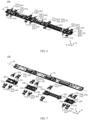
- FIG. 6 is a schematic diagram of a structure of the rotating mechanism 100 of the electronic device shown in FIG. 5 .
- FIG. 7 is a schematic exploded view of the rotating mechanism 100 shown in FIG. 6 .
- the rotating mechanism 100 may include a base 10, a bracket 20, a rotating swing arm assembly 30, and a pressing plate swing arm assembly 40.
- the bracket 20 is mounted on the base 10, and the bracket 20 is fixedly connected to the base 10.
- the rotating swing arm assembly 30 is mounted on the bracket 20 and may rotate relative to the bracket 20.
- a rotating connection between the base 10 and the rotating swing arm assembly 30 can be implemented through a rotating connection between the rotating swing arm assembly 30 and the bracket 20.
- the pressing plate swing arm assembly 40 is mounted on the bracket 20 and may rotate relative to the bracket 20.
- a rotating connection between the base 10 and the pressing plate swing arm assembly 40 can be implemented through a rotating connection between the pressing plate swing arm assembly 40 and the bracket 20.
- the pressing plate swing arm assembly 40 may be slidably and rotatably connected to the rotating swing arm assembly 30.
- the rotating swing arm assembly 30 rotates relative to the base 10
- the pressing plate swing arm assembly 40 is driven to rotate relative to the base 10, thereby implementing the rotation of the rotating mechanism 100, so that the rotating mechanism 100 switches between the folded state and the unfolded state.
- a symmetry axis O (as shown in FIG. 6 ) is disposed in this embodiment of this application.
- the symmetry axis O is perpendicular to a direction X, and the symmetry axis O passes through a center of the rotating mechanism 100.
- FIG. 6 and FIG. 7 are only intended to schematically describe a connection relationship between the base 10, the bracket 20, and the rotating swing arm assembly 30, and are not to specifically limit a connection position, a specific structure, and a quantity of each device.
- the structure illustrated in this embodiment of this application does not constitute a specific limitation on the rotating mechanism 100.
- the rotating mechanism 100 may include more or fewer components than those shown in the figure, or some components may be combined, or some components may be split, or components are arranged in different manners.
- the components shown in the figure may be implemented by hardware, software, or a combination thereof.
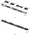
- FIG. 8 is a schematic diagram of structures of the base 10 and the bracket 20 of the rotating mechanism 100 shown in FIG. 6 .
- FIG. 9 is a schematic diagram of assembling of the bracket 20 and the base 10 shown in FIG. 8 .
- the base 10 may include a bottom plate 11, a first end plate 12, and a second end plate 13.
- the first end plate 12 and the second end plate 13 are respectively connected to two sides of the bottom plate 11.
- the first end plate 12 is disposed opposite to the second end plate 13 in the direction Y
- a plurality of mounting columns 14 are disposed on the bottom plate 11.
- the plurality of mounting columns 14 are disposed on the bottom plate 11 at intervals. In the direction X, the plurality of mounting columns 14 on one side of the bottom plate 11 and the plurality of mounting columns 14 on the other side of the bottom plate 11 are symmetrically disposed relative to the symmetry axis O.
- the bracket 20 is fixedly connected to the base 10.
- the bracket 20 is disposed opposite to the bottom plate 11 of the base 10.
- the bracket 20 and the base 10 may be fixedly connected in a manner of using a bolt, using glue, welding, or the like.
- the bracket 20 includes four sub-brackets.
- the four sub-brackets are of a separated structure in this embodiment.
- the four sub-brackets are a first sub-bracket 201, a second sub-bracket 202, a third sub-bracket 203, and a fourth sub-bracket 204.
- the first sub-bracket 201, the second sub-bracket 202, the third sub-bracket 203, and the fourth sub-bracket 204 are sequentially arranged in the direction Y
- the first sub-bracket 201 is located on one side of a negative direction toward a Y-axis of the base 10, and the fourth sub-bracket 204 is located on one side of a positive direction toward the Y-axis.
- the four sub-brackets may alternatively be of an integrally formed structure.
- FIG. 10 is a schematic diagram of a structure of the first sub-bracket 201 of the bracket 20 shown in FIG. 6 .
- the first sub-bracket 201 is fixedly connected to the base 10.
- a first rotating groove 21a and a second rotating groove 22a are disposed on the first sub-bracket 201.
- the first rotating groove 21a and the second rotating groove 22a are disposed at intervals in both the direction X and the direction Y Orthographic projections that are of the first rotating groove 21a and the second rotating groove 22a and that are on the base 10 may entirely fall on the base 10.
- the first sub-bracket 201 is enabled to match arrangement of structures of the first rotating groove 21a and the second rotating groove 22a, and the first sub-bracket 201 is also located in a space range defined by the base 10, so that a size of the first sub-bracket 201 can match a size of the base 10, and the first sub-bracket 201 do not protrude relative to the base 10. In other words, the first rotating groove 21a and the second rotating groove 22a do not protrude relative to the base 10. Under this arrangement, impact on a thickness of an entire machine due to the protruding of the first sub-bracket 201 relative to the base 10 can be minimized, to help implement lightening and thinning of the entire machine.
- both the first rotating groove 21a and the second rotating groove 22a are of an integrated structure.
- the first rotating groove 21a and the second rotating groove 22a that are of the integrated structure have advantages such as no disassembling, a small quantity of parts, simple machining and manufacturing, low costs, and high size precision.
- An adverse effect caused by a problem caused by the splicing of the plurality of parts, such as large assembly tolerance, existence of a diastema and misalignment, high welding difficulty, and high repair difficulty, can be minimized, and reliability is good.
- the first rotating groove 21a may include a first sliding rail 211a and two second sliding rails 212a.
- the first sliding rail 211a is disposed on a bottom wall of the first rotating groove 21a.
- the two second sliding rails 212a are respectively located on two side walls that are disposed opposite to each other and that are of the first rotating groove 21a.
- the two second sliding rails 212a are respectively located on two opposite sides of the first sliding rail 211a.
- the two second sliding rails 212a are disposed side by side with the first sliding rail 211a in a length direction (the direction Y) of the bracket 20.
- the bottom wall of the first rotating groove 21a is curved.
- the first sliding rail 211a and the second sliding rail 212a enable the swing arms to slide thereon.
- a rotating movement of the swing arms and the first sub-bracket 201 can be implemented.
- the first rotating groove 21a (a sliding groove of the swing arm) is disposed on the first sub-bracket 201, so that space on the first sub-bracket 201 can be fully utilized to properly arrange a structure of the first rotating groove 21a.
- the swing arm occupies small space in a folded state, to help implement lightening and thinning of an entire machine.
- first sliding rail 211a and the two second sliding rails 212a are disposed in the first rotating groove 21a, so that a sliding trajectory of the swing arm is jointly limited by the first sliding rail 211a and the two second sliding rails 212a.
- the sliding trajectory of the swing arm is jointly limited by the first sliding rail 211a and the two second sliding rails 212a, so that a precision requirement on the first rotating groove 21a can be reduced, thereby reducing machining difficulty and machining costs of the first sub-bracket 201.
- the sliding trajectory of the swing arm is jointly limited by the first sliding rail 211a and the two second sliding rails 212a, so that the first sliding rail 211a and the two second sliding rails 212a are arranged in a distributed manner.
- the plurality of sliding rails arranged in the distributed manner can increase strength of the first rotating groove 21a, so that the swing arm is not easily deformed and stuck when the swing arm slides on the sliding rails, and reliability is good.
- FIG. 11 is a schematic top view of the first sub-bracket 201 shown in FIG. 10 .
- the first sliding rail 211a may include a first connecting portion 213a and two first convex portions 214a.
- the first connecting portion 213a and the two first convex portions 214a are all connected to the bottom wall of the first rotating groove 21a.
- the two first convex portions 214a are disposed opposite to each other at intervals in the direction Y
- a surface that is of each first convex portion 214a and that is away from the bottom wall of the first rotating groove 21a is a rail surface of the first sliding rail 211a.
- Each first convex portion 214a includes a first end 215a and a second end 216a.
- the first end 215a is an end that is of the first convex portion 214a and that is close to an edge of the first sub-bracket 201.
- the second end 216a is an end that is of the first convex portion 214a and that is away from the edge of the first sub-bracket 201.
- the first end 215a is disposed closer to the edge of the first sub-bracket 201 in comparison with the second end 216a.
- a height of a cross section that is of each first convex portion 214a and that is in a direction perpendicular to the bottom wall of the first rotating groove 21a gradually decreases from the first end 215a to the second end 216a.
- the first end 215a can be a high point position in the first convex portion 214a
- the second end 216a can be a low point position in the first convex portion 214a, so that a rail path of the first sliding rail 211a is arranged to gradually approach from the edge of the first sub-bracket 201 to a center of the first sub-bracket 201 from high to low, to help fully utilize structure space of the first sub-bracket 201, so as to achieve a rail arrangement in which the first sliding rail 211a has a high-low drop and an inclined angle, and reliability is good.
- the first convex portion 214a may be curved.
- a bending direction of the first convex portion 214a is approximately the same as a bending direction of the bottom wall of the first rotating groove 21a.
- the first connecting portion 213a is connected between the first ends 215a of the two first convex portions 214a. In other words, the first connecting portion 213a is disposed close to the edge of the first sub-bracket 201.
- the first connecting portion 213a and the two first convex portions 214a cooperate to enclose mounting space C1.
- a mounting hole D1 is disposed on a groove bottom wall of the first rotating groove 21a. The mounting hole D1 penetrates the groove bottom wall of the first rotating groove 21a in the direction Z.
- the mounting hole D1 is located between the two first convex portions 214a and disposed close to the first connecting portion 213a.
- the mounting hole D1 and a mounting column 14 on the base 10 are correspondingly disposed, so that the mounting column 14 on the base 10 can pass through the mounting hole D1 to be located in the mounting space C1.
- rapid positioning can be implemented through a corresponding arrangement of the mounting hole D1 and the mounting column 14, to help easily and quickly assemble the first sub-bracket 201 to the base 10.
- a clamping connection between the first sub-bracket 201 and the base 10 can be implemented through the corresponding arrangement of the mounting hole D1 and the mounting column 14, so that a relative movement between the first sub-bracket 201 and the base 10 is limited, and it is ensured that a displacement situation such as incline, misalignment, or shaking does not occur between the first sub-bracket 201 and the base 10.
- the mounting column 14 may be accommodated in the mounting space C1 formed through the cooperation of the first connecting portion 213a and the two convex portions, so that the space of the first sub-bracket 201 can be fully utilized without additionally occupying space of the rotating mechanism 100, to effectively improve space utilization of the first sub-bracket 201.
- Each second sliding rail 212a is disposed at intervals with the first sliding rail 211a.
- the two second sliding rails 212a may be symmetrically distributed on two sides of the first sliding rail 211a.
- Bus direction of the two second sliding rails 212a may be the same as that of the first sliding rail 211a.
- Each second sliding rail 212a includes a first bump 217a and a first rail structure 218a.
- the first bump 217a is connected to a side wall of the first rotating groove 21a.
- the first rail structure 218a is connected to the bottom wall of the first rotating groove 21a.
- the first bump 217a and the first rail structure 218a are disposed at intervals.
- a gap area between the first bump 217a and the first rail structure 218a enables the swing arm to slide therein.
- the first bump 217a is disposed on the side wall of the first rotating groove 21a, so that the swing arm mounted in the first rotating groove 21a can be limited, to help avoid a case that the swing arm mounted in the first rotating groove 21a leaves the first rotating groove 21a.
- the first rail structure 218a may be curved.
- a first hollowed-out portion 219a is disposed on the first rail structure 218a.
- the first hollowed-out portion 219a is disposed opposite to the first bump 217a.
- the first hollowed-out portion 219a penetrates the bottom wall of the first rotating groove 21a in the direction Z. It may be understood that, the arrangement of the first hollowed-out portion 219a can enable the first sub-bracket 201 to be made through mold shaping, thereby simplifying a machining process of the first sub-bracket 201, to help reduce production costs and improve production efficiency.
- the second rotating groove 22a may include a third sliding rail 221a and two fourth sliding rails 222a.
- the third sliding rail 221a is disposed on a bottom wall of the second rotating groove 22a.
- the two fourth sliding rails 222a are respectively located on two side walls that are disposed opposite to each other and that are of the second rotating groove 22a.
- the two fourth sliding rails 222a are respectively located on two opposite sides of the third sliding rail 221a.
- the two fourth sliding rails 222a are disposed side by side with the third sliding rail 221a in the length direction (the direction Y) of the bracket 20.
- the bottom wall of the second rotating groove 22a is curved.
- the third sliding rail 221a and the fourth sliding rail 222a enable the swing arms to slide thereon.
- the rotating movement of the swing arms and the first sub-bracket 201 can be implemented.
- the second rotating groove 22a (a sliding groove of the swing arm) is disposed on the first sub-bracket 201, so that the space on the first sub-bracket 201 can be fully utilized to properly arrange a structure of the second rotating groove 22a.
- the swing arm occupies small space in the folded state, to help implement lightening and thinning of the entire machine.
- the third sliding rail 221a and the two fourth sliding rails 222a are disposed in the second rotating groove 22a, so that the sliding trajectory of the swing arm is jointly limited by the third sliding rail 221a and the two fourth sliding rails 222a.
- the sliding trajectory of the swing arm is jointly limited by the third sliding rail 221a and the two fourth sliding rails 222a, so that a precision requirement on the second rotating groove 22a can be reduced, thereby reducing the machining difficulty and the machining costs of the first sub-bracket 201.
- the third sliding rail 221a may include a second connecting portion 223a and two second convex portions 224a.
- the second connecting portion 223a and the two second convex portions 224a are all connected to the bottom wall of the second rotating groove 22a.
- the two second convex portions 224a are disposed opposite to each other at intervals in the direction Y
- a surface that is of each second convex portion 224a and that is away from the bottom wall of the second rotating groove 22a is a rail surface of the third sliding rail 221a.
- Each second convex portion 224a includes a third end 225a and a fourth end 226a.
- the third end 225a is an end that is of the second convex portion 224a and that is close to the edge of the first sub-bracket 201.
- the fourth end 226a is an end that is of the second convex portion 224a and that is away from the edge of the first sub-bracket 201.
- the third end 225a is disposed closer to the edge of the first sub-bracket 201 in comparison with the fourth end 226a.
- a height of a cross section that is of each second convex portion 224a and that is in a direction perpendicular to the bottom wall of the second rotating groove 22a gradually decreases from the third end 225a to the fourth end 226a.
- the third end 225a can be a high point position in the second convex portion 224a
- the fourth end 226a can be a low point position in the second convex portion 224a, so that a rail path of the third sliding rail 221a is arranged to gradually approach from the edge of the first sub-bracket 201 to the center of the first sub-bracket 201 from high to low, to help fully utilize the structure space of the first sub-bracket 201, so as to achieve a rail arrangement in which the third sliding rail 221a has a high-low drop and an inclined angle, and reliability is good.
- the second convex portion 224a may be curved.
- a bending direction of the second convex portion 224a is approximately the same as a bending direction of the bottom wall of the second rotating groove 22a.
- the second connecting portion 223a is connected between the third ends 225a of the two second convex portions 224a. In other words, the second connecting portion 223a is disposed close to the edge of the first sub-bracket 201.
- the second connecting portion 223a and the two second convex portions 224a cooperate to enclose mounting space C2.
- a mounting hole D2 is disposed on a groove bottom wall of the second rotating groove 22a. The mounting hole D2 penetrates the groove bottom wall of the second rotating groove 22a in the direction Z. The mounting hole D2 is located between the two second convex portions 224a and disposed close to the second connecting portion 223a.
- the mounting hole D2 and the mounting column 14 on the base 10 are correspondingly disposed, so that the mounting column 14 on the base 10 can pass through the mounting hole D2 to be located in the mounting space C2.
- the rapid positioning can be implemented through a corresponding arrangement of the mounting hole D2 and the mounting column 14, to help easily and quickly assemble the first sub-bracket 201 to the base 10.
- the clamping connection between the first sub-bracket 201 and the base 10 can be implemented through the corresponding arrangement of the mounting hole D2 and the mounting column 14, so that the relative movement between the first sub-bracket 201 and the base 10 is limited, and it is ensured that a displacement situation such as incline, misalignment, or shaking does not occur between the first sub-bracket 201 and the base 10.
- the mounting column 14 may be accommodated in the mounting space C2 formed through the cooperation of the second connecting portion 223a and the two convex portions, so that the space of the first sub-bracket 201 can be fully utilized without additionally occupying the space of the rotating mechanism 100, to effectively improve the space utilization of the first sub-bracket 201.
- Each fourth sliding rail 222a is disposed at intervals with the third sliding rail 221a.
- the two fourth sliding rails 222a may be symmetrically distributed on two sides of the third sliding rail 221a.
- a bend direction of the two fourth sliding rails 222a may be the same as that of the third sliding rail 221a.
- Each fourth sliding rail 222a includes a second bump 227a and a second rail structure 228a.
- the second bump 227a is connected to a side wall of the second rotating groove 22a.
- the second rail structure 228a is connected to the bottom wall of the second rotating groove 22a.
- the second bump 227a and the second rail structure 228a are disposed at intervals.
- a gap area between the second bump 227a and the second rail structure 228a enables the swing arm to slide therein.
- the second bump 227a is disposed on the side wall of the second rotating groove 22a, so that the swing arm mounted in the second rotating groove 22a can be limited, to help avoid a case that the swing arm mounted in the second rotating groove 22a leaves the second rotating groove 22a.
- the second rail structure 228a may be curved.
- a second hollowed-out portion 229a is disposed on the second rail structure 228a.
- the second hollowed-out portion 229a is disposed opposite to the second bump 227a.
- the second hollowed-out portion 229a penetrates the bottom wall of the second rotating groove 22a in the direction Z. It may be understood that, the arrangement of the second hollowed-out portion 229a can enable the first sub-bracket 201 to be made through the mold shaping, thereby simplifying the machining process of the first sub-bracket 201, to help reduce the production costs and improve the production efficiency.
- a third rotating groove 23a and a fourth rotating groove 24a are further disposed on the first sub-bracket 201.
- the third rotating groove 23a and the fourth rotating groove 24a are disposed at intervals in both the direction X and the direction Y
- the third rotating groove 23a is disposed side by side with the first rotating groove 21a in the direction Y
- a structure of the third rotating groove 23a is approximately the same as that of the first rotating groove 21a.
- the third rotating groove 23a may include a fifth sliding rail 231a and two sixth sliding rails 232a.
- the fifth sliding rail 231a is disposed on a bottom wall of the third rotating groove 23a.
- the two sixth sliding rails 232a are respectively disposed on two opposite side walls of the third rotating groove 23a.
- the foregoing related descriptions of the first sliding rail 211a and the second sliding rail 212a in the first rotating groove 21a can be applied to the fifth sliding rail 231a and the sixth sliding rail 232a without conflict.
- the fourth rotating groove 24a is disposed side by side with the second rotating groove 22a in the direction Y A structure of the fourth rotating groove 24a is approximately the same as that of the second rotating groove 22a.
- the fourth rotating groove 24a includes a seventh sliding rail 241a and two eighth sliding rails 242a.
- the seventh sliding rail 241a is disposed on a bottom wall of the fourth rotating groove 24a.
- the two eighth sliding rails 242a are respectively disposed on two opposite side walls of the fourth rotating groove 24a.
- For structure designs of the seventh sliding rail 241a and the eighth sliding rail 242a refer to the foregoing related descriptions of the third sliding rail 221a and the fourth sliding rail 222a in the second rotating groove 22a.
- the foregoing structure descriptions of the third sliding rail 221a and the fourth sliding rail 222a can be applied to the seventh sliding rail 241a and the eighth sliding rail 242a without conflict.
- the second sub-bracket 202 and the first sub-bracket 201 may be a same or similar assembly, symmetrical or partially symmetrical structures, or different structures.
- the second sub-bracket 202 may include a first rotating groove 21b, a second rotating groove 22b, a third rotating groove 23b, and a fourth rotating groove 24b.
- the first rotating groove 21b and the second rotating groove 22b are disposed side by side in the direction X.
- the first rotating groove 21b and the second rotating groove 22b are symmetric relative to the symmetry axis O-axis.
- the third rotating groove 23b and the fourth rotating groove 24b are disposed side by side in the direction X.
- the third rotating groove 23b and the fourth rotating groove 24b are symmetric relative to the symmetry axis O-axis.
- the third rotating groove 23b and the first rotating groove 21b are disposed side by side in the direction Y
- the fourth rotating groove 24b and the second rotating groove 22b are disposed side by side in the direction Y
- a connection relationship between the components, and a connection relationship between the components and a component outside an assembly refer to the related design of the first sub-bracket 201.
- the second sub-bracket 202 and the first sub-bracket 201 may be the same or different in terms of a detailed structure or a position arrangement of the components.
- the third sub-bracket 203 and the first sub-bracket 201 may be a same or similar assembly, symmetrical or partially symmetrical structures, or different structures.
- the third sub-bracket 203 includes a first rotating groove 21c and a second rotating groove 22c.
- the first rotating groove 21c and the second rotating groove 22c are disposed side by side in the direction X.
- the first rotating groove 21c and the second rotating groove 22c are symmetric relative to the symmetry axis O-axis.
- a connection relationship between the components, and a connection relationship between the components and a component outside an assembly refer to the related design of the first sub-bracket 201.
- the fourth sub-bracket 204 and the first sub-bracket 201 may be a same or similar assembly, symmetrical or partially symmetrical structures, or different structures.
- the fourth sub-bracket 204 includes a first rotating groove 21d, a second rotating groove 22d, a third rotating groove 23d, and a fourth rotating groove 24d.
- the first rotating groove 21d and the second rotating groove 22d are disposed side by side in the direction X.
- the first rotating groove 21d and the second rotating groove 22d are symmetric relative to the symmetry axis O-axis.
- the third rotating groove 23d and the fourth rotating groove 24d are disposed side by side in the direction X.
- the third rotating groove 23d and the fourth rotating groove 24d are symmetric relative to the symmetry axis O-axis.
- the third rotating groove 23d and the first rotating groove 21d are disposed side by side in the direction Y
- the fourth rotating groove 24d and the second rotating groove 22d are disposed side by side in the direction Y
- a connection relationship between the components, and a connection relationship between the components and a component outside an assembly refer to the related design of the first sub-bracket 201.
- the four rotating swing arm assemblies 30 are a first rotating swing arm assembly 301, a second rotating swing arm assembly 302, a third rotating swing arm assembly 303, and a fourth rotating swing arm assembly 304.
- the first rotating swing arm assembly 301, the second rotating swing arm assembly 302, the third rotating swing arm assembly 303, and the fourth rotating swing arm assembly 304 are sequentially arranged in the direction Y
- the first rotating swing arm assembly 301 is located on one side of the negative direction toward the Y-axis of the base 10
- the fourth rotating swing arm assembly 304 is located on one side of the positive direction toward the Y-axis of the base 10.
- a quantity of the rotating swing arm assembly 30 is not specifically limited in this application.
- FIG. 12 is a schematic diagram of a structure of the first rotating swing arm assembly 301 of the rotating swing arm assemblies 30 shown in FIG. 6 .
- the first rotating swing arm assembly 301 may include a first main swing arm 31a and a second main swing arm 32a.
- the first main swing arm 31a and the second main swing arm 32a are disposed at intervals in both the direction X and the direction Y
- the first main swing arm 31a is mounted in the first rotating groove 21a of the first sub-bracket 201.
- the first main swing arm 31a can rotate and slide relative to the first sub-bracket 201.
- the first main swing arm 31a may also be rotatably connected to a first fixing plate (not shown in the figure), so that when the first fixing plate rotates relative to the first sub-bracket 201, the first main swing arm 31a is driven to rotate and slide relative to the first sub-bracket 201.
- the first fixing plate may also be fixedly connected to the first housing 210, so that when the first housing 210 rotates relative to the first sub-bracket 201, the first fixing plate is driven to rotate relative to the first sub-bracket 201, to drive the first main swing arm 31a to rotate.
- FIG. 13 is a schematic diagram of a state in which a part of the rotating mechanism 100 shown in FIG. 6 is in an unfolded state.
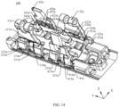
- FIG. 14 is a schematic diagram of a state in which a part of the rotating mechanism 100 shown in FIG. 6 is in a folded state.
- the first main swing arm 31a may include a first rotating body 311a, a first swing body 312a, and a first rotary shaft 313a.
- the first rotating body 311a is of a circular arc-shaped plate structure.
- the first rotating body 311a can slide and rotate along the first sliding rail 211a and the second sliding rail 212a in the first rotating groove 21a.
- the first rotating body 311a includes a first sliding portion 314a and two second sliding portions 315a.
- the two second sliding portions 315a are respectively connected to two opposite sides that are of the first sliding portion 314a and that are in the direction X.
- the first sliding portion 314a is located between the two second sliding portions 315a.
- the first sliding portion 314a is mounted on the first sliding rail 211a, and the first sliding portion 314a can slide on the first sliding rail 211a.
- Each second sliding portion 315a is mounted on one second sliding rail 212a.
- Each second sliding portion 315a can slide on one second sliding rail 212a.
- each second sliding portion 315a is located in the gap area between one first bump 217a and one first rail structure 218a.
- a structure of the first rotating body 311a can match the structure of the first rotating groove 21a of the first sub-bracket 201
- a structure of the first sliding portion 314a can match a structure of the first sliding rail 211a
- a structure of the second sliding portion 315a can match a structure of the second sliding rail 212a, to facilitate a smooth rotating movement of the first main swing arm 31a relative to the first sub-bracket 201.
- the first sliding portion 314a and the two second sliding portions 315a cooperate to form a first concave area 316a.
- the first sliding rail 211a can be partially accommodated in the first concave area 316a.
- the first sliding portion 314a is concave inward relative to the two second sliding portions 315a.
- the first concave area 316a formed by the first sliding portion 314a being concave inward relative to the two second sliding portions 315a can provide space to accommodate the first sliding rail 211a, to help improve space utilization of the rotating mechanism 100 in a limited space layout, and reliability is good.
- a first through hole 317a is further disposed on the first rotating body 311a.
- the first through hole 317a is in communication with the first concave area 316a.
- the first through hole 317a is for the first sliding rail 211a to pass through.
- the first sliding rail 211a and a rotating movement of the first main swing arm 31a can be prevented from affecting each other, to effectively avoid a problem that the rotating mechanism 100 is stuck because the first sliding rail 211a hinders the rotation of the first main swing arm 31a.
- the first swing body 312a is of a plate structure. One end of the first swing body 312a is fixedly connected to the first rotating body 311a, and the other end is fixedly connected to the first rotary shaft 313a. An extension direction of an axis center of the first rotary shaft 313a is parallel to the direction Y, and the first rotary shaft 313a may be fixedly connected to the first fixing plate.
- the second main swing arm 32a is mounted in the second rotating groove 22a of the first sub-bracket 201.
- the second main swing arm 32a can rotate and slide relative to the first sub-bracket 201.
- the second main swing arm 32a may also be rotatably connected to a second fixing plate (not shown in the figure), so that when the second fixing plate rotates relative to the first sub-bracket 201, the second main swing arm 32a is driven to rotate and slide relative to the bracket 20.
- the second fixing plate may also be fixedly connected to the second housing 220, so that when the second housing 220 rotates relative to the first sub-bracket 201, the second fixing plate is driven to rotate relative to the first sub-bracket 201, to drive the second main swing arm 32a to rotate.
- the second main swing arm 32a is mounted in the fourth rotating groove 24a of the first sub-bracket 201.
- the second main swing arm 32a can rotate and slide relative to the first sub-bracket 201.
- the second main swing arm 32a may also be rotatably connected to the second fixing plate (not shown in the figure), so that when the second fixing plate rotates relative to the first sub-bracket 201, the second main swing arm 32a is driven to rotate and slide relative to the first sub-bracket 201.
- the second fixing plate may also be fixedly connected to the second housing 220, so that when the second housing 220 rotates relative to the first sub-bracket 201, the second fixing plate is driven to rotate relative to the first sub-bracket 201, to drive the second main swing arm 32a to rotate.
- the second main swing arm 32a may include a second rotating body 321a, a second swing body 322a, and a second rotary shaft 323a.
- the second rotating body 321a is of a circular arc-shaped plate structure.
- the second rotating body 321a can slide and rotate along the third sliding rail 221a and the fourth sliding rail 222a in the second rotating groove 22a.
- the second rotating body 321a includes a third sliding portion 324a and two fourth sliding portions 325a.
- the two fourth sliding portions 325a are respectively connected to two opposite sides that are of the third sliding portion 324a and that are in the direction X.
- the third sliding portion 324a is located between the two fourth sliding portions 325a.
- the third sliding portion 324a is mounted on the third sliding rail 221a, and the third sliding portion 324a can slide on the third sliding rail 221a.
- Each fourth sliding portion 325a is mounted on one fourth sliding rail 222a.
- Each fourth sliding portion 325a can slide on one fourth sliding rail 222a.
- each fourth sliding portion 325a is located in the gap area between one second bump 227a and one second rail structure 228a.
- a structure of the second rotating body 321a can match the structure of the second rotating groove 22a of the first sub-bracket 201
- a structure of the third sliding portion 324a can match a structure of the third sliding rail 221a
- a structure of the fourth sliding portion 325a can match a structure of the fourth sliding rail 222a, to facilitate a smooth rotating movement of the second main swing arm 32a relative to the first sub-bracket 201.
- the third sliding portion 324a and the two fourth sliding portions 325a cooperate to form a second concave area 326a.
- the third sliding rail 221a can be partially accommodated in the second concave area 326a.
- the third sliding portion 324a is concave inward relative to the two fourth sliding portions 325a.
- the second concave area 326a formed by the third sliding portion 324a being concave inward relative to the two fourth sliding portions 325a can provide space to accommodate the third sliding rail 221a, to help improve the space utilization of the rotating mechanism 100 in the limited space layout, and the reliability is good.
- a second through hole 327a is further disposed on the second rotating body 321a.
- the second through hole 327a is in communication with the second concave area 326a.
- the second through hole 327a is for the second sliding rail 212a to pass through.
- the second sliding rail 212a and a rotating movement of the second main swing arm 32a can be prevented from affecting each other, to effectively avoid a problem that the rotating mechanism 100 is stuck because the second sliding rail 212a hinders the rotation of the second main swing arm 32a.
- the second swing body 322a is of a plate structure. One end of the second swing body 322a is fixedly connected to the second rotating body 321a, and the other end is fixedly connected to the second rotary shaft 323a. An extension direction of an axis center of the second rotary shaft 323a is parallel to the direction Y, and the second rotary shaft 323a may be fixedly connected to the second fixing plate.
- a rotation direction of the first main swing arm 31a is opposite to that of the second main swing arm 32a.
- the rotating mechanism 100 switches from a flattened state to the folded state, the first main swing arm 31a rotates clockwise, and the second main swing arm 32a rotates anticlockwise.
- the rotating mechanism 100 switches from the folded state to the flattened state, the first main swing arm 31a rotates anticlockwise, and the second main swing arm 32a rotates clockwise.
- the second rotating swing arm assembly 302 and the first rotating swing arm assembly 301 may be a same or similar assembly, symmetrical or partially symmetrical structures, or different structures.
- the second rotating swing arm assembly 302 includes a first main swing arm 31b and a second main swing arm 32b.
- the first main swing arm 31b may be mounted in the first rotating groove 21b of the second sub-bracket 202.
- the second main swing arm 32b may be mounted in the second rotating groove 22b of the second sub-bracket 202.
- the first main swing arm 31b and the second main swing arm 32b are disposed side by side in the direction X.
- the first main swing arm 31b and the second main swing arm 32b are symmetric relative to the symmetry axis O-axis.
- a connection relationship between the components, and a connection relationship between the components and a component outside an assembly refer to the related design of the first rotating swing arm assembly 301.
- the second rotating swing arm assembly 302 and the first rotating swing arm assembly 301 may be the same or different in terms of a detailed structure or a position arrangement of the components. This is not specifically limited in this application.
- the third rotating swing arm assembly 303 and the first rotating swing arm assembly 301 may be a same or similar assembly, symmetrical or partially symmetrical structures, or different structures.
- the third rotating swing arm assembly 303 includes a first main swing arm 31c and a second main swing arm 32c.
- the first main swing arm 31c may be mounted in the first rotating groove 21c of the third sub-bracket 203.
- the second main swing arm 32c may be mounted in the second rotating groove 22c of the third sub-bracket 203.
- the first main swing arm 31c and the second main swing arm 32c are disposed side by side in the direction X.
- the first main swing arm 31c and the second main swing arm 32c are symmetric relative to the symmetry axis O-axis.
- a connection relationship between the components, and a connection relationship between the components and a component outside an assembly refer to the related design of the first rotating swing arm assembly 301.
- the third rotating swing arm assembly 303 and the first rotating swing arm assembly 301 may be the same or different in terms of a detailed structure or a position arrangement of the components. This is not specifically limited in this application.
- the fourth rotating swing arm assembly 304 and the first rotating swing arm assembly 301 may be a same or similar assembly, symmetrical or partially symmetrical structures, or different structures.
- the fourth rotating swing arm assembly 304 includes a first main swing arm 31d and a second main swing arm 32d.
- the first main swing arm 31d may be mounted in the first rotating groove 21d of the fourth sub-bracket 204.
- the second main swing arm 32d may be mounted in the second rotating groove 22d of the fourth sub-bracket 204.
- the first main swing arm 31d and the second main swing arm 32d are disposed side by side in the direction X.
- the first main swing arm 31d and the second main swing arm 32d are symmetric relative to the symmetry axis O-axis.
- a connection relationship between the components, and a connection relationship between the components and a component outside an assembly refer to the related design of the first rotating swing arm assembly 301.
- the fourth rotating swing arm assembly 304 and the first rotating swing arm assembly 301 may be the same or different in terms of a detailed structure or a position arrangement of the components. This is not specifically limited in this application.
- the three pressing plate swing arm assemblies 40 are a first pressing plate swing arm assembly 401, a second pressing plate swing arm assembly 402, and a third pressing plate swing arm assembly 403.
- the first pressing plate swing arm assembly 401, the second pressing plate swing arm assembly 402, and the third pressing plate swing arm assembly 403 are sequentially arranged in the direction Y
- the first pressing plate swing arm assembly 401 is located on one side of the negative direction toward the Y-axis of the base 10
- the third pressing plate swing arm assembly 403 is located on one side of the positive direction toward the Y-axis of the base 10.
- a quantity of the pressing plate swing arm assembly 40 is not specifically limited in this application.
- FIG. 15 is a schematic diagram of a structure of the first pressing plate swing arm assembly 401 of the pressing plate swing arm assemblies 40 shown in FIG. 6 .
- the first pressing plate swing arm assembly 401 may include a first pressing plate swing arm 41a and a second pressing plate swing arm 42a.
- the first pressing plate swing arm 41a and the second pressing plate swing arm 42a are disposed at intervals in both the direction X and the direction Y
- the first pressing plate swing arm 41a is mounted in the third rotating groove 23a of the first sub-bracket 201.
- the first pressing plate swing arm 41a can rotate and slide relative to the first sub-bracket 201.
- the first pressing plate swing arm 41a may also be slidably connected to a first pressing plate (not shown in the figure).
- the first pressing plate may be slidably connected to the first fixing plate. In this way, when the first fixing plate rotates relative to the first sub-bracket 201, the first pressing plate swing arm 41a is driven to rotate and slide relative to the first sub-bracket 201.
- the first fixing plate is driven by the first housing 210 to rotate relative to the first sub-bracket 201
- the first pressing plate is driven by the first fixing plate to rotate relative to the first sub-bracket 201
- the first pressing plate slides relative to the first fixing plate.
- the first pressing plate swing arm 41a is driven by the first pressing plate to rotate relative to the first sub-bracket 201.
- FIG. 13 is a schematic diagram of a state in which a part of the rotating mechanism 100 shown in FIG. 6 is in an unfolded state.
- FIG. 14 is a schematic diagram of a state in which a part of the rotating mechanism 100 shown in FIG. 6 is in a folded state.
- the first pressing plate swing arm 41a may include a first pressing plate swing body 411a and a first pressing plate rotating body 412a.
- the first pressing plate rotating body 412a is of a circular arc-shaped plate structure.
- the first pressing plate rotating body 412a can slide and rotate along the fifth sliding rail 231a and the sixth sliding rail 232a in the third rotating groove 23a.
- the first pressing plate rotating body 412a includes a fifth sliding portion 413a and two sixth sliding portions 414a.
- the two sixth sliding portions 414a are respectively connected to two opposite sides that are of the fifth sliding portion 413a and that are in the direction X.
- the fifth sliding portion 413a is located between the two sixth sliding portions 414a.
- the fifth sliding portion 413a is mounted on the fifth sliding rail 231a, and the fifth sliding portion 413a can slide on the fifth sliding rail 231a.
- Each sixth sliding portion 414a is mounted on one sixth sliding rail 232a. Each sixth sliding portion 414a can slide on one sixth sliding rail 232a. Under this arrangement, a structure of the first pressing plate rotating body 412a can match the structure of the third rotating groove 23a of the first sub-bracket 201, a structure of the fifth sliding portion 413a can match a structure of the fifth sliding rail 23 1a, and a structure of the sixth sliding portion 414a can match a structure of the sixth sliding rail 232a, to facilitate a smooth rotating movement of the first pressing plate swing arm 41a relative to the first sub-bracket 201.
- the fifth sliding portion 413a and the two sixth sliding portions 414a cooperate to form a third concave area 415a.
- the fifth sliding rail 231a can be partially accommodated in the third concave area 415a.
- the fifth sliding portion 413a is concave inward relative to the two sixth sliding portions 414a.
- the third concave area 415a formed by the fifth sliding portion 413a being concave inward relative to the two sixth sliding portions 414a can provide space to accommodate the fifth sliding rail 231a, to help improve the space utilization of the rotating mechanism 100 in the limited space layout, and the reliability is good.
- a third through hole 416a is further disposed on the first pressing plate rotating body 412a.
- the third through hole 416a is in communication with the third concave area 415a.
- the third through hole 416a is for the fifth sliding rail 231a to pass through.
- the fifth sliding rail 231a and a rotating movement of the first pressing plate swing arm 41a can be prevented from affecting each other, to effectively avoid a problem that the rotating mechanism 100 is stuck because the fifth sliding rail 231a hinders the rotation of the first pressing plate swing arm 41a.
- the first pressing plate swing body 411a is of a plate structure. One end of the first pressing plate swing body 411a is fixedly connected to the first pressing plate rotating body 412a, and the other end is slidably connected to the first pressing plate.
- the second pressing plate swing arm 42a is mounted in the fourth rotating groove 24a of the first sub-bracket 201.
- the second pressing plate swing arm 42a can rotate and slide relative to the first sub-bracket 201.
- the second pressing plate swing arm 42a may also be slidably connected to a second pressing plate (not shown in the figure).
- the second pressing plate may be slidably connected to the second fixing plate. In this way, when the second fixing plate rotates relative to the first sub-bracket 201, the second pressing plate swing arm 42a is driven to rotate and slide relative to the first sub-bracket 201.
- the second fixing plate is driven by the second housing 220 to rotate relative to the first sub-bracket 201
- the second pressing plate is driven by the second fixing plate to rotate relative to the first sub-bracket 201
- the second pressing plate slides relative to the second fixing plate.
- the second pressing plate swing arm 42a is driven by the second pressing plate to rotate relative to the first sub-bracket 201.
- the second pressing plate swing arm 42a may include a second pressing plate swing body 421a and a second pressing plate rotating body 422a.
- the second pressing plate rotating body 422a is of a circular arc-shaped plate structure.
- the second pressing plate rotating body 422a can slide and rotate along the seventh sliding rail 241a and the eighth sliding rail 242a in the fourth rotating groove 24a.
- the second pressing plate rotating body 422a includes a seventh sliding portion 423a and two eighth sliding portions 424a.
- the two eighth sliding portions 424a are respectively connected to two opposite sides that are of the seventh sliding portion 423a and that are in the direction X.
- the seventh sliding portion 423a is located between the two eighth sliding portions 424a.
- the seventh sliding portion 423a is mounted on the seventh sliding rail 241a, and the seventh sliding portion 423a can slide on the seventh sliding rail 241a.
- Each eighth sliding portion 424a is mounted on one eighth sliding rail 242a.
- Each eighth sliding portion 424a can slide on one eighth sliding rail 242a.
- a structure of the second pressing plate rotating body 422a can match the structure of the fourth rotating groove 24a of the first sub-bracket 201
- a structure of the seventh sliding portion 423a can match a structure of the seventh sliding rail 241a
- a structure of the eighth sliding portion 424a can match a structure of the eighth sliding rail 242a, to facilitate a smooth rotating movement of the second pressing plate swing arm 42a relative to the first sub-bracket 201.
- the seventh sliding portion 423a and the two eighth sliding portions 424a cooperate to form a fourth concave area 425a.
- the seventh sliding rail 241a can be partially accommodated in the fourth concave area 425a.
- the seventh sliding portion 423a is concave inward relative to the two eighth sliding portions 424a.
- the fourth concave area 425a formed by the seventh sliding portion 423a being concave inward relative to the two eighth sliding portions 424a can provide space to accommodate the seventh sliding rail 241a, to help improve the space utilization of the rotating mechanism 100 in the limited space layout, and the reliability is good.
- a fourth through hole 426a is further disposed on the second pressing plate rotating body 422a.
- the fourth through hole 426a is in communication with the fourth concave area 425a.
- the fourth through hole 426a is for the seventh sliding rail 241a to pass through.
- the seventh sliding rail 241a and a rotating movement of the second pressing plate swing arm 42a can be prevented from affecting each other, to effectively avoid a problem that the rotating mechanism 100 is stuck because the seventh sliding rail 241a hinders the rotation of the second pressing plate swing arm 42a.
- the second pressing plate swing body 421a is of a plate structure. One end of the second pressing plate swing body 421a is fixedly connected to the second pressing plate rotating body 422a, and the other end is slidably connected to the second pressing plate.
- a rotation direction of the first pressing plate swing arm 41a is opposite to that of the second pressing plate swing arm 42a.
- the rotating mechanism 100 switches from a flattened state to the folded state, the first pressing plate swing arm 41a rotates clockwise, and the second pressing plate swing arm 42a rotates anticlockwise.
- the rotating mechanism 100 switches from the folded state to the flattened state, the first pressing plate swing arm 41a rotates anticlockwise, and the second pressing plate swing arm 42a rotates clockwise.
- the second pressing plate swing arm assembly 402 and the first pressing plate swing arm assembly 401 may be a same or similar assembly, symmetrical or partially symmetrical structures, or different structures.
- the second pressing plate swing arm assembly 402 includes a first pressing plate swing arm 41b and a second pressing plate swing arm 42b.
- the first pressing plate swing arm 41b may be mounted in the third rotating groove 23b of the second sub-bracket 202.
- the second pressing plate swing arm 42b may be mounted in the fourth rotating groove 24b of the second sub-bracket 202.
- the first pressing plate swing arm 41b and the second pressing plate swing arm 42b are disposed side by side in the direction X.
- the first pressing plate swing arm 41b and the second pressing plate swing arm 42b are symmetric relative to the symmetry axis O-axis.
- a connection relationship between the components, and a connection relationship between the components and a component outside an assembly refer to a related design of the first pressing plate swing arm assembly 401.
- the second pressing plate swing arm assembly 402 and the first pressing plate swing arm assembly 401 may be the same or different in terms of a detailed structure or a position arrangement of the components. This is not specifically limited in this application.
- the third pressing plate swing arm assembly 403 and the first pressing plate swing arm assembly 401 may be a same or similar assembly, symmetrical or partially symmetrical structures, or different structures.
- the third pressing plate swing arm assembly 403 includes a first pressing plate swing arm 41c and a second pressing plate swing arm 42c.
- the first pressing plate swing arm 41c may be mounted in the third rotating groove 23c of the fourth sub-bracket 204.
- the second pressing plate swing arm 42c may be mounted in the fourth rotating groove 24c of the fourth sub-bracket 204.
- the first pressing plate swing arm 41c and the second pressing plate swing arm 42c are disposed side by side in the direction X.
- the first pressing plate swing arm 41c and the second pressing plate swing arm 42c are symmetric relative to the symmetry axis O-axis.
- a connection relationship between the components, and a connection relationship between the components and a component outside an assembly refer to the related design of the first pressing plate swing arm assembly 401.
- the third pressing plate swing arm assembly 403 and the first pressing plate swing arm assembly 401 may be the same or different in terms of a detailed structure or a position arrangement of the components. This is not specifically limited in this application.
Landscapes
- Engineering & Computer Science (AREA)
- Theoretical Computer Science (AREA)
- Computer Hardware Design (AREA)
- Physics & Mathematics (AREA)
- Human Computer Interaction (AREA)
- General Engineering & Computer Science (AREA)
- General Physics & Mathematics (AREA)
- Mathematical Physics (AREA)
- Microelectronics & Electronic Packaging (AREA)
- Signal Processing (AREA)
- Telephone Set Structure (AREA)
Abstract
Description
- This application claims priority to
Chinese Patent Application No. 202211146001.8, filed with the China National Intellectual Property Administration on September 20, 2022 - This application relates to the field of electronic product technologies, and in particular, to a rotating mechanism and an electronic device.
- As technologies of a flexible foldable screen become more mature, a foldable terminal product is more widely applied. The foldable terminal product (such as a foldable mobile phone, a foldable tablet, or a foldable computer) needs to satisfy a good appearance form and good experience, to be accepted by a consumer. Currently, the foldable terminal product often implements a rotating movement by using a swing arm mounted on a shaft cover bracket. However, existing arrangement of a structure of a sliding groove of the swing arm easily affects a thickness of the entire machine.
- Embodiments of this application provide a rotating mechanism and an electronic device. Arrangement of a structure of the rotating mechanism is conductive to reducing a thickness of an entire machine on a basis of ensuring a rotating movement of a swing arm.
- According to a first aspect, this application provides a rotating mechanism. The rotating mechanism includes a bracket, a first main swing arm, and a second main swing arm.
- A first rotating groove and a second rotating groove are disposed on the bracket. The first rotating groove and the second rotating groove are distributed on two opposite sides of the bracket.
- The first rotating groove includes a first sliding rail and two second sliding rails. The two second sliding rails are respectively located on two opposite sides of the first sliding rail, and are disposed side by side with the first sliding rail in a length direction of the bracket. The first main swing arm is mounted in the first rotating groove. The first main swing arm can slide on the first sliding rail and the two second sliding rails. The first main swing arm can rotate relative to the bracket.
- The second rotating groove includes a third sliding rail and two fourth sliding rails. The two fourth sliding rails are respectively located on two opposite sides of the third sliding rail, and are disposed side by side with the third sliding rail in the length direction of the bracket. The second main swing arm is mounted in the second rotating groove. The second main swing arm can slide on the third sliding rail and the two fourth sliding rails. The second main swing arm can rotate relative to the bracket. A rotation direction of the second main swing arm is opposite to that of the first main swing arm.
- It may be understood that, the first sliding rail and the second sliding rail enable the swing arms to slide thereon. Through a sliding movement of the swing arms on the first sliding rail and the second sliding rail, a rotating movement of the swing arms and the bracket can be implemented. Under this arrangement, the first rotating groove (a sliding groove of the swing arm) is disposed on the bracket, so that space on the bracket can be fully utilized to properly arrange a structure of the first rotating groove. In comparison with a structure in which the sliding groove of the swing arm is disposed on the swing arm in a conventional technology, the swing arm occupies small space in a folded state, to help implement lightening and thinning of an entire machine.
- In addition, the first sliding rail and the two second sliding rails are disposed in the first rotating groove, so that a sliding trajectory of the swing arm is jointly limited by the first sliding rail and the two second sliding rails. On one hand, the sliding trajectory of the swing arm is jointly limited by the first sliding rail and the two second sliding rails, so that a precision requirement on the first rotating groove can be reduced, thereby reducing machining difficulty and machining costs of the bracket. On the other hand, the sliding trajectory of the swing arm is jointly limited by the first sliding rail and the two second sliding rails, so that the first sliding rail and the two second sliding rails are arranged in a distributed manner. The plurality of sliding rails arranged in the distributed manner can increase strength of the first rotating groove, so that the swing arm is not easily deformed and stuck when the swing arm slides on the sliding rails, and reliability is good.
- An effect of the second rotating groove is the same.
- In a possible implementation, the first main swing arm includes a first sliding portion and two second sliding portions. The two second sliding portions are connected to two opposite sides of the first sliding portion. The first sliding portion is mounted on the first sliding rail. Each second sliding portion is mounted on one second sliding rail.
- Under this arrangement, a structure of a first rotating body can match the structure of the first rotating groove of the bracket, a structure of the first sliding portion can match a structure of the first sliding rail, and a structure of the second sliding portion can match a structure of the second sliding rail, to facilitate a smooth rotating movement of the first main swing arm relative to the bracket.
- In a possible implementation, the first sliding portion and the two second sliding portions cooperate to form a first concave area. The first sliding rail is partially located in the first concave area.
- Under this arrangement, the first sliding portion is concave inward relative to the two second sliding portions. When the first sliding portion slides on the first sliding rail, the first concave area formed by the first sliding portion being concave inward relative to the two second sliding portions can provide space to accommodate the first sliding rail, to help improve space utilization of the rotating mechanism in a limited space layout, and reliability is good.
- In a possible implementation, a first through hole is disposed on the first main swing arm. The first through hole is in communication with the first concave area. The first through hole is for the first sliding rail to pass through.
- Under this arrangement, the first sliding rail and a rotating movement of the first main swing arm can be prevented from affecting each other, to effectively avoid a problem that the rotating mechanism is stuck because the first sliding rail hinders the rotation of the first main swing arm.
- In a possible implementation, the first sliding rail includes two first convex portions disposed opposite to each other. A surface that is of each first convex portion and that is away from a bottom wall of the first rotating groove is in contact with the first sliding portion. Each first convex portion includes a first end and a second end, and the first end is disposed closer to an edge of the bracket in comparison with the second end. A height of a cross section that is of each first convex portion and that is in a direction perpendicular to the bottom wall of the first rotating groove gradually decreases from the first end to the second end.
- Under this arrangement, the first end can be a high point position in the first convex portion, and the second end can be a low point position in the first convex portion, so that a rail path of the first sliding rail is arranged to gradually approach from the edge of the bracket to a center of the bracket from high to low, to help fully utilize structure space of the bracket, so as to achieve a rail arrangement in which the first sliding rail has a high-low drop and an inclined angle, and reliability is good.
- In a possible implementation, the rotating mechanism further includes a base. The bracket is fixed to the base. A mounting column is disposed on the base. The first sliding rail further includes a first connecting portion. The first connecting portion is connected between the first ends of the two first convex portions. The first connecting portion and the two first convex portions cooperate to enclose mounting space. A mounting hole is disposed on the bracket. The mounting hole is located between the two first convex portions and disposed close to the first connecting portion. The mounting column passes through the mounting hole. The mounting column is located in the mounting space.
- Under this arrangement, on one hand, when the bracket and the base are assembled, rapid positioning can be implemented through a corresponding arrangement of the mounting hole and the mounting column, to help easily and quickly assemble the bracket to the base. On the other hand, a clamping connection between the bracket and the base can be implemented through the corresponding arrangement of the mounting hole and the mounting column, so that a relative movement between the bracket and the base is limited, and it is ensured that a displacement situation such as incline, misalignment, or shaking does not occur between the bracket and the base. In addition, the mounting column may be accommodated in the mounting space formed through the cooperation of the first connecting portion and the two convex portions, so that the space of the bracket can be fully utilized without additionally occupying space of the rotating mechanism, to effectively improve space utilization of the bracket.
- In a possible implementation, each first sliding rail includes a first bump and a first rail structure. The first bump is connected to a side wall of the first rotating groove. The first rail structure is connected to the bottom wall of the first rotating groove. The first bump and the first rail structure are disposed at intervals. The second sliding portion is located in a gap area between the first bump and the first rail structure.
- The first bump is disposed on the side wall of the first rotating groove, so that the swing arm mounted in the first rotating groove can be limited, to help avoid a case that the swing arm mounted in the first rotating groove leaves the first rotating groove. For example, the first rail structure may be curved.
- In a possible implementation, a first hollowed-out portion is disposed on the first rail structure. The first hollowed-out portion is disposed opposite to the first bump. The first hollowed-out portion penetrates the bottom wall of the first rotating groove.
- It may be understood that, the arrangement of the first hollowed-out portion can enable the bracket to be made through mold shaping, thereby simplifying a machining process of the bracket, to help reduce production costs and improve production efficiency.
- In a possible implementation, the first rotating groove and the second rotating groove are of an integrated structure.
- It may be understood that, both the first rotating groove and the second rotating groove are of the integrated structure. In comparison with an assembled structure in which the rotating groove is formed by splicing a plurality of parts in a conventional technology, the first rotating groove and the second rotating groove that are of the integrated structure have advantages such as no disassembling, a small quantity of parts, simple machining and manufacturing, low costs, and high size precision. An adverse effect caused by a problem caused by the splicing of the plurality of parts, such as large assembly tolerance, existence of a diastema and misalignment, high welding difficulty, and high repair difficulty, can be minimized, and reliability is good.
- In a possible implementation, the rotating mechanism further includes the base. The bracket is fixed to the base. Orthographic projections that are of the first rotating groove and the second rotating groove and that are on the base entirely fall on the base.
- It may be understood that, because the orthographic projections of the first rotating groove and the second rotating groove entirely fall on the base, the bracket is enabled to match arrangement of the structures of the first rotating groove and the second rotating groove, and the bracket is also located in a space range defined by the base, so that a size of the bracket can match a size of the base, and the bracket do not protrude relative to the base. In other words, the first rotating groove and the second rotating groove do not protrude relative to the base. Under this arrangement, impact on a thickness of the entire machine due to the protruding of the bracket relative to the base can be minimized, to help implement lightening and thinning of the entire machine.
- According to a second aspect, this application further provides an electronic device. The electronic device includes a first housing, a second housing, and the foregoing rotating mechanism. The rotating mechanism is connected between the first housing and the second housing.
-
-
FIG. 1 is a simplified schematic diagram of a structure of an electronic device in a folded state according to an embodiment of this application; -
FIG. 2 is a simplified schematic diagram of a structure of the electronic device shown inFIG. 1 in an intermediate state; -
FIG. 3 is a simplified schematic diagram of a structure of the electronic device shown inFIG. 1 in an unfolded state; -
FIG. 4 is a schematic diagram of a structure of an electronic device according to an embodiment of this application; -
FIG. 5 is a schematic exploded view of the electronic device shown inFIG. 4 ; -
FIG. 6 is a schematic diagram of a structure of a rotating mechanism of the electronic device shown inFIG. 5 ; -
FIG. 7 is a schematic exploded view of the rotating mechanism shown inFIG. 6 ; -
FIG. 8 is a schematic diagram of structures of a base and a bracket of the rotating mechanism shown inFIG. 6 ; -
FIG. 9 is a schematic diagram of assembling of the bracket and the base shown inFIG. 8 ; -
FIG. 10 is a schematic diagram of a structure of a first sub-bracket of a bracket shown inFIG. 6 ; -
FIG. 11 is a schematic top view of the first sub-bracket shown inFIG. 10 ; -
FIG. 12 is a schematic diagram of a structure of a first rotating swing arm assembly of rotating swing arm assemblies shown inFIG. 6 ; -
FIG. 13 is a schematic diagram of a state in which a part of the rotating mechanism shown inFIG. 6 is in an unfolded state; -
FIG. 14 is a schematic diagram of a state in which a part of the rotating mechanism shown inFIG. 6 is in a folded state; and -
FIG. 15 is a schematic diagram of a structure of a first pressing plate swing arm assembly of pressing plate swing arm assemblies shown inFIG. 6 . - For ease of understanding, terms in embodiments of this application are first described.
- A term "and/or" describes only an association relationship for describing associated objects and represents that three relationships may exist. For example, A and/or B may represent the following three cases: only A exists, both A and B exist, and only B exists.
- A term "a plurality of" refers to two or more.
- A term "connection" should be understood in a broad sense. For example, a connection between A and B may be a direct connection between A and B, or an indirect connection between A and B by using an intermediary.
- The following describes specific implementations of this application in detail with reference to the accompanying drawings.
- Embodiments of this application provide a rotating mechanism and an electronic device using the rotating mechanism. Arrangement of a structure of the rotating mechanism is conductive to reducing a thickness of an entire machine on a basis of ensuring a rotating movement of a swing arm.
- The electronic device may be any device with foldable performance, and can be unfolded and folded through an operation of a user. The electronic device includes but is not limited to a mobile phone (cellphone), a notebook computer (notebook computer), a tablet personal computer (tablet personal computer), a laptop computer (laptop computer), a personal digital assistant (personal digital assistant), a wearable device (wearable device), a vehicle-mounted device (mobile device), or the like. In embodiments of this application, an example in which the electronic device is a mobile phone is used for description.
-
FIG. 1 is a simplified schematic diagram of a structure of anelectronic device 400 in a folded state according to an embodiment of this application.FIG. 2 is a simplified schematic diagram of a structure of theelectronic device 400 shown inFIG. 1 in an intermediate state.FIG. 3 is a simplified schematic diagram of a structure of theelectronic device 400 shown inFIG. 1 in an unfolded state. An unfolding angle α of theelectronic device 400 shown inFIG. 2 is 120 degrees, and an unfolding angle β of theelectronic device 400 shown inFIG. 3 is 180 degrees. - For ease of description, a length direction of the
electronic device 400 is defined as a direction X, a width direction of theelectronic device 400 is defined as a direction Y, and a thickness direction of theelectronic device 400 is defined as a direction Z. The direction X, the direction Y, and the direction Z are perpendicular to each other. - It should be noted that the angle illustrated in this embodiment of this application is allowed to have a slight deviation. For example, that the unfolding angle α of the
electronic device 400 shown inFIG. 2 is 120 degrees means that α may be 120 degrees or approximately 120 degrees, such as 110 degrees, 115 degrees, 125 degrees, or 130 degrees. That the unfolding angle β of theelectronic device 400 shown inFIG. 3 is 180 degrees means that β may be 180 degrees or approximately 180 degrees, such as 0 degrees, 5 degrees, 185 degrees, or 190 degrees. An angle used as an example for description in the following specification may be understood in a same way. - The
electronic device 400 shown in this embodiment of this application is an electronic device that can be folded once. In some other embodiments, theelectronic device 400 may alternatively be an electronic device that can be folded for a plurality of times (at least twice). In this case, theelectronic device 400 may include a plurality of parts. Two adjacent parts may be folded relatively close to each other until theelectronic device 400 is in a folded state, and the two adjacent parts may be unfolded relatively away from each other until theelectronic device 400 is in an unfolded state. -
FIG. 4 is a schematic diagram of a structure of anelectronic device 400 according to an embodiment of this application.FIG. 5 is a schematic exploded view of theelectronic device 400 shown inFIG. 4 . - Refer to
FIG. 4 andFIG. 5 together. Theelectronic device 400 includes afoldable apparatus 200 and aflexible display screen 300. Theflexible display screen 300 is mounted on thefoldable apparatus 200. Theflexible display screen 300 includes afirst part 310, asecond part 320, and afoldable part 330. Thefoldable part 330 is located between thefirst part 310 and thesecond part 320, and thefoldable part 330 may be bent. Thefirst part 310, thesecond part 320, and thefoldable part 330 jointly constitute theflexible display screen 300. - In this embodiment, the
flexible display screen 300 may be an organic light-emitting diode (organic light-emitting diode, OLED) display, an active-matrix organic light-emitting diode (active-matrix organic light-emitting diode, AMOLED) display, a mini light-emitting diode (mini organic lightemitting diode) display, a micro light-emitting diode (micro organic light-emitting diode) display, a micro organic light-emitting diode (micro organic light-emitting diode) display, or a quantum dot light-emitting diode (quantum dot light emitting diodes, QLED) display. - The
foldable apparatus 200 includes afirst housing 210, asecond housing 220, and arotating mechanism 100. A firstaccommodating groove 230 is disposed on thefirst housing 210. A secondaccommodating groove 240 is disposed on thesecond housing 220. The firstaccommodating groove 230 is in communication with the secondaccommodating groove 240 to form an accommodating groove. Therotating mechanism 100 is mounted in the accommodating groove and fixedly connected to thefirst housing 210 and thesecond housing 220, to achieve a rotating connection between thefirst housing 210 and thesecond housing 220. Thefirst housing 210 and thesecond housing 220 may rotate relative to each other through therotating mechanism 100, so that thefoldable apparatus 200 switches between the folded state and the unfolded state. Accommodating space (not shown in the figure) is further disposed between thefirst housing 210 and thesecond housing 220. The accommodating space is for accommodating an electronic element, such as a processor, a circuit board, or a camera module, and a structural element of theelectronic device 400. - As shown in
FIG. 1 , that the relative rotation of thefirst housing 210 and thesecond housing 220 enables thefoldable apparatus 200 to be in the folded state means that thefirst housing 210 and thesecond housing 220 rotate through therotating mechanism 100 and approach each other. Surfaces that are of thefirst housing 210 and thesecond housing 220 and that carry theflexible display screen 300 are opposite to each other. Actually, during application, when thefoldable apparatus 200 is in a fully folded state, after theflexible display screen 300 mounted on thefirst housing 210 and thesecond housing 220 is folded, thefirst part 310 and thesecond part 320 are stacked and partially in contact, or certainly, may be fully in contact. - As shown in
FIG. 2 , that the relative rotation of thefirst housing 210 and thesecond housing 220 enables thefoldable apparatus 200 to be in an intermediate state means that thefirst housing 210 and thesecond housing 220 rotate through therotating mechanism 100 and move away from each other, and an included angle between thefirst housing 210 and thesecond housing 220 becomes larger. Alternatively, it means that thefirst housing 210 and thesecond housing 220 rotate through therotating mechanism 100 and approach each other, and the included angle between thefirst housing 210 and thesecond housing 220 becomes smaller. - As shown in
FIG. 3 , that the relative rotation of thefirst housing 210 and thesecond housing 220 enables thefoldable apparatus 200 to be in an unfolded state means that thefirst housing 210 and thesecond housing 220 rotate through therotating mechanism 100 and move away from each other, and the included angle between thefirst housing 210 and thesecond housing 220 continues to increase, and may be close to 180 degrees or equal to 180 degrees. - The
flexible display screen 300 is connected to thefoldable apparatus 200. Specifically, thefirst housing 210 carries thefirst part 310 of theflexible display screen 300, thesecond housing 220 carries thesecond part 320 of theflexible display screen 300, and thefoldable part 330 of theflexible display screen 300 is disposed opposite to therotating mechanism 100. It may be understood that, thefirst housing 210 and thesecond housing 220 rotate relative to each other through therotating mechanism 100. Thefirst housing 210 and thesecond housing 220 relatively approach each other to drive theflexible display screen 300 to be folded, so thatelectronic device 400 is folded. When theelectronic device 400 is in the folded state, thefoldable part 330 of theflexible display screen 300 is bent, and thefirst part 310 is disposed opposite to thesecond part 320. In this case, theflexible display screen 300 is located between thefirst housing 210 and thesecond housing 220, so that a probability of damaging theflexible display screen 300 can be greatly reduced, and theflexible display screen 300 is effectively protected. - In this embodiment of this application, the
first housing 210 and thesecond housing 220 rotate relative to each other through therotating mechanism 100. Thefirst housing 210 and thesecond housing 220 relatively move away from each other to drive theflexible display screen 300 to be unfolded, so thatelectronic device 400 is unfolded to the intermediate state. When theelectronic device 400 is in the intermediate state, thefirst housing 210 and thesecond housing 220 are unfolded to have an included angle α. Thefirst part 310 and thesecond part 320 are unfolded relative to each other, and drive thefoldable part 330 to be unfolded. In this case, the included angle between thefirst part 310 and thesecond part 320 is α. In this embodiment, α is 120 degrees. In another embodiment, α may alternatively be approximately 120 degrees, such as 110 degrees, 115 degrees, 125 degrees, or 130 degrees. - The
first housing 210 and thesecond housing 220 rotate relative to each other through therotating mechanism 100. Thefirst housing 210 and thesecond housing 220 relatively move away from each other to drive theflexible display screen 300 to be further unfolded until theelectronic device 400 is unfolded. When thefoldable apparatus 200 is in the unfolded state, an included angle between thefirst housing 210 and thesecond housing 220 is β. Thefoldable part 330 is unfolded, and thefirst part 310 and thesecond part 320 are unfolded relative to each other. In this case, included angles between thefirst part 310, thesecond part 320, and thefoldable part 330 are all β. Theflexible display screen 300 has a large display area, to implement large-screen display of theelectronic device 400 and improve user experience. In this embodiment, β is 180 degrees. In another embodiment, β may alternatively be approximately 180 degrees, such as 0 degrees, 5 degrees, 185 degrees, or 190 degrees. - Refer to
FIG. 6 and FIG. 7 together.FIG. 6 is a schematic diagram of a structure of therotating mechanism 100 of the electronic device shown inFIG. 5 .FIG. 7 is a schematic exploded view of therotating mechanism 100 shown inFIG. 6 . - The
rotating mechanism 100 may include abase 10, a bracket 20, a rotatingswing arm assembly 30, and a pressing plateswing arm assembly 40. The bracket 20 is mounted on thebase 10, and the bracket 20 is fixedly connected to thebase 10. The rotatingswing arm assembly 30 is mounted on the bracket 20 and may rotate relative to the bracket 20. A rotating connection between the base 10 and the rotatingswing arm assembly 30 can be implemented through a rotating connection between the rotatingswing arm assembly 30 and the bracket 20. The pressing plateswing arm assembly 40 is mounted on the bracket 20 and may rotate relative to the bracket 20. A rotating connection between the base 10 and the pressing plateswing arm assembly 40 can be implemented through a rotating connection between the pressing plateswing arm assembly 40 and the bracket 20. For example, the pressing plateswing arm assembly 40 may be slidably and rotatably connected to the rotatingswing arm assembly 30. When the rotatingswing arm assembly 30 rotates relative to thebase 10, the pressing plateswing arm assembly 40 is driven to rotate relative to thebase 10, thereby implementing the rotation of therotating mechanism 100, so that therotating mechanism 100 switches between the folded state and the unfolded state. - For ease of description, a symmetry axis O (as shown in
FIG. 6 ) is disposed in this embodiment of this application. The symmetry axis O is perpendicular to a direction X, and the symmetry axis O passes through a center of therotating mechanism 100. - It should be noted that,
FIG. 6 and FIG. 7 are only intended to schematically describe a connection relationship between the base 10, the bracket 20, and the rotatingswing arm assembly 30, and are not to specifically limit a connection position, a specific structure, and a quantity of each device. The structure illustrated in this embodiment of this application does not constitute a specific limitation on therotating mechanism 100. In some other embodiments of this application, therotating mechanism 100 may include more or fewer components than those shown in the figure, or some components may be combined, or some components may be split, or components are arranged in different manners. The components shown in the figure may be implemented by hardware, software, or a combination thereof. - Refer to
FIG. 8 and FIG. 9. FIG. 8 is a schematic diagram of structures of thebase 10 and the bracket 20 of therotating mechanism 100 shown inFIG. 6 .FIG. 9 is a schematic diagram of assembling of the bracket 20 and the base 10 shown inFIG. 8 . The base 10 may include a bottom plate 11, afirst end plate 12, and asecond end plate 13. Thefirst end plate 12 and thesecond end plate 13 are respectively connected to two sides of the bottom plate 11. Thefirst end plate 12 is disposed opposite to thesecond end plate 13 in the direction Y A plurality of mountingcolumns 14 are disposed on the bottom plate 11. The plurality of mountingcolumns 14 are disposed on the bottom plate 11 at intervals. In the direction X, the plurality of mountingcolumns 14 on one side of the bottom plate 11 and the plurality of mountingcolumns 14 on the other side of the bottom plate 11 are symmetrically disposed relative to the symmetry axis O. - The bracket 20 is fixedly connected to the
base 10. The bracket 20 is disposed opposite to the bottom plate 11 of thebase 10. For example, the bracket 20 and the base 10 may be fixedly connected in a manner of using a bolt, using glue, welding, or the like. In this embodiment of this application, the bracket 20 includes four sub-brackets. The four sub-brackets are of a separated structure in this embodiment. The four sub-brackets are afirst sub-bracket 201, asecond sub-bracket 202, athird sub-bracket 203, and afourth sub-bracket 204. Thefirst sub-bracket 201, thesecond sub-bracket 202, thethird sub-bracket 203, and thefourth sub-bracket 204 are sequentially arranged in the direction Y Thefirst sub-bracket 201 is located on one side of a negative direction toward a Y-axis of thebase 10, and thefourth sub-bracket 204 is located on one side of a positive direction toward the Y-axis. Certainly, in some other embodiments, the four sub-brackets may alternatively be of an integrally formed structure. -
FIG. 10 is a schematic diagram of a structure of thefirst sub-bracket 201 of the bracket 20 shown inFIG. 6 . - The
first sub-bracket 201 is fixedly connected to thebase 10. A firstrotating groove 21a and a secondrotating groove 22a are disposed on thefirst sub-bracket 201. The firstrotating groove 21a and the secondrotating groove 22a are disposed at intervals in both the direction X and the direction Y Orthographic projections that are of the firstrotating groove 21a and the secondrotating groove 22a and that are on thebase 10 may entirely fall on thebase 10. It may be understood that, because the orthographic projections of the firstrotating groove 21a and the secondrotating groove 22a entirely fall on thebase 10, thefirst sub-bracket 201 is enabled to match arrangement of structures of the firstrotating groove 21a and the secondrotating groove 22a, and thefirst sub-bracket 201 is also located in a space range defined by thebase 10, so that a size of thefirst sub-bracket 201 can match a size of thebase 10, and thefirst sub-bracket 201 do not protrude relative to thebase 10. In other words, the firstrotating groove 21a and the secondrotating groove 22a do not protrude relative to thebase 10. Under this arrangement, impact on a thickness of an entire machine due to the protruding of thefirst sub-bracket 201 relative to the base 10 can be minimized, to help implement lightening and thinning of the entire machine. - In this embodiment of this application, both the first
rotating groove 21a and the secondrotating groove 22a are of an integrated structure. In comparison with an assembled structure in which the rotating groove is formed by splicing a plurality of parts in a conventional technology, the firstrotating groove 21a and the secondrotating groove 22a that are of the integrated structure have advantages such as no disassembling, a small quantity of parts, simple machining and manufacturing, low costs, and high size precision. An adverse effect caused by a problem caused by the splicing of the plurality of parts, such as large assembly tolerance, existence of a diastema and misalignment, high welding difficulty, and high repair difficulty, can be minimized, and reliability is good. - Still refer to
FIG. 10 . The firstrotating groove 21a may include a first slidingrail 211a and two second slidingrails 212a. The first slidingrail 211a is disposed on a bottom wall of the firstrotating groove 21a. The two second slidingrails 212a are respectively located on two side walls that are disposed opposite to each other and that are of the firstrotating groove 21a. The two second slidingrails 212a are respectively located on two opposite sides of the first slidingrail 211a. The two second slidingrails 212a are disposed side by side with the first slidingrail 211a in a length direction (the direction Y) of the bracket 20. For example, the bottom wall of the firstrotating groove 21a is curved. - It may be understood that, the first sliding
rail 211a and the second slidingrail 212a enable the swing arms to slide thereon. Through a sliding movement of the swing arms on the first slidingrail 211a and the second slidingrail 212a, a rotating movement of the swing arms and thefirst sub-bracket 201 can be implemented. Under this arrangement, the firstrotating groove 21a (a sliding groove of the swing arm) is disposed on thefirst sub-bracket 201, so that space on thefirst sub-bracket 201 can be fully utilized to properly arrange a structure of the firstrotating groove 21a. In comparison with a structure in which the sliding groove of the swing arm is disposed on the swing arm in a conventional technology, the swing arm occupies small space in a folded state, to help implement lightening and thinning of an entire machine. - In addition, the first sliding
rail 211a and the two second slidingrails 212a are disposed in the firstrotating groove 21a, so that a sliding trajectory of the swing arm is jointly limited by the first slidingrail 211a and the two second slidingrails 212a. On one hand, the sliding trajectory of the swing arm is jointly limited by the first slidingrail 211a and the two second slidingrails 212a, so that a precision requirement on the firstrotating groove 21a can be reduced, thereby reducing machining difficulty and machining costs of thefirst sub-bracket 201. On the other hand, the sliding trajectory of the swing arm is jointly limited by the first slidingrail 211a and the two second slidingrails 212a, so that the first slidingrail 211a and the two second slidingrails 212a are arranged in a distributed manner. The plurality of sliding rails arranged in the distributed manner can increase strength of the firstrotating groove 21a, so that the swing arm is not easily deformed and stuck when the swing arm slides on the sliding rails, and reliability is good. - Refer to
FIG. 10 and FIG. 11 together.FIG. 11 is a schematic top view of thefirst sub-bracket 201 shown inFIG. 10 . The first slidingrail 211a may include a first connectingportion 213a and two firstconvex portions 214a. The first connectingportion 213a and the two firstconvex portions 214a are all connected to the bottom wall of the firstrotating groove 21a. - The two first
convex portions 214a are disposed opposite to each other at intervals in the direction Y A surface that is of each firstconvex portion 214a and that is away from the bottom wall of the firstrotating groove 21a is a rail surface of the first slidingrail 211a. Each firstconvex portion 214a includes afirst end 215a and asecond end 216a. Thefirst end 215a is an end that is of the firstconvex portion 214a and that is close to an edge of thefirst sub-bracket 201. Thesecond end 216a is an end that is of the firstconvex portion 214a and that is away from the edge of thefirst sub-bracket 201. In other words, thefirst end 215a is disposed closer to the edge of thefirst sub-bracket 201 in comparison with thesecond end 216a. A height of a cross section that is of each firstconvex portion 214a and that is in a direction perpendicular to the bottom wall of the firstrotating groove 21a gradually decreases from thefirst end 215a to thesecond end 216a. Under this arrangement, thefirst end 215a can be a high point position in the firstconvex portion 214a, and thesecond end 216a can be a low point position in the firstconvex portion 214a, so that a rail path of the first slidingrail 211a is arranged to gradually approach from the edge of thefirst sub-bracket 201 to a center of the first sub-bracket 201 from high to low, to help fully utilize structure space of thefirst sub-bracket 201, so as to achieve a rail arrangement in which the first slidingrail 211a has a high-low drop and an inclined angle, and reliability is good. For example, the firstconvex portion 214a may be curved. A bending direction of the firstconvex portion 214a is approximately the same as a bending direction of the bottom wall of the firstrotating groove 21a. - The first connecting
portion 213a is connected between the first ends 215a of the two firstconvex portions 214a. In other words, the first connectingportion 213a is disposed close to the edge of thefirst sub-bracket 201. The first connectingportion 213a and the two firstconvex portions 214a cooperate to enclose mounting space C1. A mounting hole D1 is disposed on a groove bottom wall of the firstrotating groove 21a. The mounting hole D1 penetrates the groove bottom wall of the firstrotating groove 21a in the direction Z. The mounting hole D1 is located between the two firstconvex portions 214a and disposed close to the first connectingportion 213a. The mounting hole D1 and a mountingcolumn 14 on thebase 10 are correspondingly disposed, so that the mountingcolumn 14 on the base 10 can pass through the mounting hole D1 to be located in the mounting space C1. Under this arrangement, on one hand, when thefirst sub-bracket 201 and the base 10 are assembled, rapid positioning can be implemented through a corresponding arrangement of the mounting hole D1 and the mountingcolumn 14, to help easily and quickly assemble thefirst sub-bracket 201 to thebase 10. On the other hand, a clamping connection between thefirst sub-bracket 201 and the base 10 can be implemented through the corresponding arrangement of the mounting hole D1 and the mountingcolumn 14, so that a relative movement between thefirst sub-bracket 201 and thebase 10 is limited, and it is ensured that a displacement situation such as incline, misalignment, or shaking does not occur between thefirst sub-bracket 201 and thebase 10. In addition, the mountingcolumn 14 may be accommodated in the mounting space C1 formed through the cooperation of the first connectingportion 213a and the two convex portions, so that the space of thefirst sub-bracket 201 can be fully utilized without additionally occupying space of therotating mechanism 100, to effectively improve space utilization of thefirst sub-bracket 201. - Still refer to
FIG. 10 and FIG. 11 . Each second slidingrail 212a is disposed at intervals with the first slidingrail 211a. The two second slidingrails 212a may be symmetrically distributed on two sides of the first slidingrail 211a. Abend direction of the two second slidingrails 212a may be the same as that of the first slidingrail 211a. Each second slidingrail 212a includes afirst bump 217a and afirst rail structure 218a. Thefirst bump 217a is connected to a side wall of the firstrotating groove 21a. Thefirst rail structure 218a is connected to the bottom wall of the firstrotating groove 21a. Thefirst bump 217a and thefirst rail structure 218a are disposed at intervals. A gap area between thefirst bump 217a and thefirst rail structure 218a enables the swing arm to slide therein. Thefirst bump 217a is disposed on the side wall of the firstrotating groove 21a, so that the swing arm mounted in the firstrotating groove 21a can be limited, to help avoid a case that the swing arm mounted in the firstrotating groove 21a leaves the firstrotating groove 21a. For example, thefirst rail structure 218a may be curved. - In this embodiment of this application, a first hollowed-
out portion 219a is disposed on thefirst rail structure 218a. The first hollowed-out portion 219a is disposed opposite to thefirst bump 217a. The first hollowed-out portion 219a penetrates the bottom wall of the firstrotating groove 21a in the direction Z. It may be understood that, the arrangement of the first hollowed-out portion 219a can enable thefirst sub-bracket 201 to be made through mold shaping, thereby simplifying a machining process of thefirst sub-bracket 201, to help reduce production costs and improve production efficiency. - The second
rotating groove 22a may include a third slidingrail 221a and two fourth slidingrails 222a. The third slidingrail 221a is disposed on a bottom wall of the secondrotating groove 22a. The two fourth slidingrails 222a are respectively located on two side walls that are disposed opposite to each other and that are of the secondrotating groove 22a. The two fourth slidingrails 222a are respectively located on two opposite sides of the third slidingrail 221a. The two fourth slidingrails 222a are disposed side by side with the third slidingrail 221a in the length direction (the direction Y) of the bracket 20. For example, the bottom wall of the secondrotating groove 22a is curved. - It may be understood that, the third sliding
rail 221a and the fourth slidingrail 222a enable the swing arms to slide thereon. Through a sliding movement of the swing arms on the third slidingrail 221a and the fourth slidingrail 222a, the rotating movement of the swing arms and thefirst sub-bracket 201 can be implemented. Under this arrangement, the secondrotating groove 22a (a sliding groove of the swing arm) is disposed on thefirst sub-bracket 201, so that the space on thefirst sub-bracket 201 can be fully utilized to properly arrange a structure of the secondrotating groove 22a. In comparison with the structure in which the sliding groove of the swing arm is disposed on the swing arm in a conventional technology, the swing arm occupies small space in the folded state, to help implement lightening and thinning of the entire machine. - In addition, the third sliding
rail 221a and the two fourth slidingrails 222a are disposed in the secondrotating groove 22a, so that the sliding trajectory of the swing arm is jointly limited by the third slidingrail 221a and the two fourth slidingrails 222a. On one hand, the sliding trajectory of the swing arm is jointly limited by the third slidingrail 221a and the two fourth slidingrails 222a, so that a precision requirement on the secondrotating groove 22a can be reduced, thereby reducing the machining difficulty and the machining costs of thefirst sub-bracket 201. On the other hand, the sliding trajectory of the swing arm is jointly limited by the third slidingrail 221a and the two fourth slidingrails 222a, so that the third slidingrail 221a and the two fourth slidingrails 222a are arranged in a distributed manner. The plurality of sliding rails arranged in the distributed manner can increase strength of the secondrotating groove 22a, so that the swing arm is not easily deformed and stuck when the swing arm slides on second sliding rails, and reliability is good. - Refer to
FIG. 10 and FIG. 11 together. The third slidingrail 221a may include a second connectingportion 223a and two secondconvex portions 224a. The second connectingportion 223a and the two secondconvex portions 224a are all connected to the bottom wall of the secondrotating groove 22a. - The two second
convex portions 224a are disposed opposite to each other at intervals in the direction Y A surface that is of each secondconvex portion 224a and that is away from the bottom wall of the secondrotating groove 22a is a rail surface of the third slidingrail 221a. Each secondconvex portion 224a includes athird end 225a and afourth end 226a. Thethird end 225a is an end that is of the secondconvex portion 224a and that is close to the edge of thefirst sub-bracket 201. Thefourth end 226a is an end that is of the secondconvex portion 224a and that is away from the edge of thefirst sub-bracket 201. In other words, thethird end 225a is disposed closer to the edge of thefirst sub-bracket 201 in comparison with thefourth end 226a. A height of a cross section that is of each secondconvex portion 224a and that is in a direction perpendicular to the bottom wall of the secondrotating groove 22a gradually decreases from thethird end 225a to thefourth end 226a. Under this arrangement, thethird end 225a can be a high point position in the secondconvex portion 224a, and thefourth end 226a can be a low point position in the secondconvex portion 224a, so that a rail path of the third slidingrail 221a is arranged to gradually approach from the edge of thefirst sub-bracket 201 to the center of the first sub-bracket 201 from high to low, to help fully utilize the structure space of thefirst sub-bracket 201, so as to achieve a rail arrangement in which the third slidingrail 221a has a high-low drop and an inclined angle, and reliability is good. For example, the secondconvex portion 224a may be curved. A bending direction of the secondconvex portion 224a is approximately the same as a bending direction of the bottom wall of the secondrotating groove 22a. - The second connecting
portion 223a is connected between the third ends 225a of the two secondconvex portions 224a. In other words, the second connectingportion 223a is disposed close to the edge of thefirst sub-bracket 201. The second connectingportion 223a and the two secondconvex portions 224a cooperate to enclose mounting space C2. A mounting hole D2 is disposed on a groove bottom wall of the secondrotating groove 22a. The mounting hole D2 penetrates the groove bottom wall of the secondrotating groove 22a in the direction Z. The mounting hole D2 is located between the two secondconvex portions 224a and disposed close to the second connectingportion 223a. The mounting hole D2 and the mountingcolumn 14 on thebase 10 are correspondingly disposed, so that the mountingcolumn 14 on the base 10 can pass through the mounting hole D2 to be located in the mounting space C2. Under this arrangement, on one hand, when thefirst sub-bracket 201 and the base 10 are assembled, the rapid positioning can be implemented through a corresponding arrangement of the mounting hole D2 and the mountingcolumn 14, to help easily and quickly assemble thefirst sub-bracket 201 to thebase 10. On the other hand, the clamping connection between thefirst sub-bracket 201 and the base 10 can be implemented through the corresponding arrangement of the mounting hole D2 and the mountingcolumn 14, so that the relative movement between thefirst sub-bracket 201 and thebase 10 is limited, and it is ensured that a displacement situation such as incline, misalignment, or shaking does not occur between thefirst sub-bracket 201 and thebase 10. In addition, the mountingcolumn 14 may be accommodated in the mounting space C2 formed through the cooperation of the second connectingportion 223a and the two convex portions, so that the space of thefirst sub-bracket 201 can be fully utilized without additionally occupying the space of therotating mechanism 100, to effectively improve the space utilization of thefirst sub-bracket 201. - Still refer to
FIG. 10 and FIG. 11 . Each fourth slidingrail 222a is disposed at intervals with the third slidingrail 221a. The two fourth slidingrails 222a may be symmetrically distributed on two sides of the third slidingrail 221a. A bend direction of the two fourth slidingrails 222a may be the same as that of the third slidingrail 221a. Each fourth slidingrail 222a includes asecond bump 227a and asecond rail structure 228a. Thesecond bump 227a is connected to a side wall of the secondrotating groove 22a. Thesecond rail structure 228a is connected to the bottom wall of the secondrotating groove 22a. Thesecond bump 227a and thesecond rail structure 228a are disposed at intervals. A gap area between thesecond bump 227a and thesecond rail structure 228a enables the swing arm to slide therein. Thesecond bump 227a is disposed on the side wall of the secondrotating groove 22a, so that the swing arm mounted in the secondrotating groove 22a can be limited, to help avoid a case that the swing arm mounted in the secondrotating groove 22a leaves the secondrotating groove 22a. For example, thesecond rail structure 228a may be curved. - In this embodiment of this application, a second hollowed-
out portion 229a is disposed on thesecond rail structure 228a. The second hollowed-out portion 229a is disposed opposite to thesecond bump 227a. The second hollowed-out portion 229a penetrates the bottom wall of the secondrotating groove 22a in the direction Z. It may be understood that, the arrangement of the second hollowed-out portion 229a can enable thefirst sub-bracket 201 to be made through the mold shaping, thereby simplifying the machining process of thefirst sub-bracket 201, to help reduce the production costs and improve the production efficiency. - Still refer to
FIG. 10 and FIG. 11 . A thirdrotating groove 23a and a fourthrotating groove 24a are further disposed on thefirst sub-bracket 201. The thirdrotating groove 23a and the fourthrotating groove 24a are disposed at intervals in both the direction X and the direction Y The thirdrotating groove 23a is disposed side by side with the firstrotating groove 21a in the direction Y A structure of the thirdrotating groove 23a is approximately the same as that of the firstrotating groove 21a. The thirdrotating groove 23a may include a fifth slidingrail 231a and two sixth slidingrails 232a. The fifth slidingrail 231a is disposed on a bottom wall of the thirdrotating groove 23a. The two sixth slidingrails 232a are respectively disposed on two opposite side walls of the thirdrotating groove 23a. For structure designs of the fifth slidingrail 231a and the sixth slidingrail 232a, refer to the foregoing related descriptions of the first slidingrail 211a and the second slidingrail 212a in the firstrotating groove 21a. The foregoing structure descriptions of the first slidingrail 211a and the second slidingrail 212a can be applied to the fifth slidingrail 231a and the sixth slidingrail 232a without conflict. The fourthrotating groove 24a is disposed side by side with the secondrotating groove 22a in the direction Y A structure of the fourthrotating groove 24a is approximately the same as that of the secondrotating groove 22a. The fourthrotating groove 24a includes a seventh slidingrail 241a and two eighth slidingrails 242a. The seventh slidingrail 241a is disposed on a bottom wall of the fourthrotating groove 24a. The two eighth slidingrails 242a are respectively disposed on two opposite side walls of the fourthrotating groove 24a. For structure designs of the seventh slidingrail 241a and the eighth slidingrail 242a, refer to the foregoing related descriptions of the third slidingrail 221a and the fourth slidingrail 222a in the secondrotating groove 22a. The foregoing structure descriptions of the third slidingrail 221a and the fourth slidingrail 222a can be applied to the seventh slidingrail 241a and the eighth slidingrail 242a without conflict. - Refer to
FIG. 7 andFIG. 8 together. Thesecond sub-bracket 202 and thefirst sub-bracket 201 may be a same or similar assembly, symmetrical or partially symmetrical structures, or different structures. In this embodiment of this application, thesecond sub-bracket 202 may include a firstrotating groove 21b, a secondrotating groove 22b, a thirdrotating groove 23b, and a fourthrotating groove 24b. The firstrotating groove 21b and the secondrotating groove 22b are disposed side by side in the direction X. The firstrotating groove 21b and the secondrotating groove 22b are symmetric relative to the symmetry axis O-axis. The thirdrotating groove 23b and the fourthrotating groove 24b are disposed side by side in the direction X. The thirdrotating groove 23b and the fourthrotating groove 24b are symmetric relative to the symmetry axis O-axis. The thirdrotating groove 23b and the firstrotating groove 21b are disposed side by side in the direction Y The fourthrotating groove 24b and the secondrotating groove 22b are disposed side by side in the direction Y For a basic structure of components in thesecond sub-bracket 202, a connection relationship between the components, and a connection relationship between the components and a component outside an assembly, refer to the related design of thefirst sub-bracket 201. Thesecond sub-bracket 202 and thefirst sub-bracket 201 may be the same or different in terms of a detailed structure or a position arrangement of the components. - The
third sub-bracket 203 and thefirst sub-bracket 201 may be a same or similar assembly, symmetrical or partially symmetrical structures, or different structures. In this embodiment, thethird sub-bracket 203 includes a firstrotating groove 21c and a secondrotating groove 22c. The firstrotating groove 21c and the secondrotating groove 22c are disposed side by side in the direction X. The firstrotating groove 21c and the secondrotating groove 22c are symmetric relative to the symmetry axis O-axis. For a basic structure of components in thethird sub-bracket 203, a connection relationship between the components, and a connection relationship between the components and a component outside an assembly, refer to the related design of thefirst sub-bracket 201. - The
fourth sub-bracket 204 and thefirst sub-bracket 201 may be a same or similar assembly, symmetrical or partially symmetrical structures, or different structures. In this embodiment, thefourth sub-bracket 204 includes a firstrotating groove 21d, a secondrotating groove 22d, a thirdrotating groove 23d, and a fourthrotating groove 24d. The firstrotating groove 21d and the secondrotating groove 22d are disposed side by side in the direction X. The firstrotating groove 21d and the secondrotating groove 22d are symmetric relative to the symmetry axis O-axis. The thirdrotating groove 23d and the fourthrotating groove 24d are disposed side by side in the direction X. The thirdrotating groove 23d and the fourthrotating groove 24d are symmetric relative to the symmetry axis O-axis. The thirdrotating groove 23d and the firstrotating groove 21d are disposed side by side in the direction Y The fourthrotating groove 24d and the secondrotating groove 22d are disposed side by side in the direction Y For a basic structure of components in thefourth sub-bracket 204, a connection relationship between the components, and a connection relationship between the components and a component outside an assembly, refer to the related design of thefirst sub-bracket 201. - Refer to
FIG. 7 again. In this embodiment of this application, there are four rotatingswing arm assemblies 30. The four rotatingswing arm assemblies 30 are a first rotatingswing arm assembly 301, a second rotatingswing arm assembly 302, a third rotating swing arm assembly 303, and a fourth rotatingswing arm assembly 304. The first rotatingswing arm assembly 301, the second rotatingswing arm assembly 302, the third rotating swing arm assembly 303, and the fourth rotatingswing arm assembly 304 are sequentially arranged in the direction Y The first rotatingswing arm assembly 301 is located on one side of the negative direction toward the Y-axis of thebase 10, and the fourth rotatingswing arm assembly 304 is located on one side of the positive direction toward the Y-axis of thebase 10. In another embodiment, there may be one, two, three, four or more rotatingswing arm assemblies 30. A quantity of the rotatingswing arm assembly 30 is not specifically limited in this application. - Refer to
FIG. 10 andFIG. 12 together.FIG. 12 is a schematic diagram of a structure of the first rotatingswing arm assembly 301 of the rotatingswing arm assemblies 30 shown inFIG. 6 . The first rotatingswing arm assembly 301 may include a firstmain swing arm 31a and a secondmain swing arm 32a. The firstmain swing arm 31a and the secondmain swing arm 32a are disposed at intervals in both the direction X and the direction Y - The first
main swing arm 31a is mounted in the firstrotating groove 21a of thefirst sub-bracket 201. The firstmain swing arm 31a can rotate and slide relative to thefirst sub-bracket 201. The firstmain swing arm 31a may also be rotatably connected to a first fixing plate (not shown in the figure), so that when the first fixing plate rotates relative to thefirst sub-bracket 201, the firstmain swing arm 31a is driven to rotate and slide relative to thefirst sub-bracket 201. The first fixing plate may also be fixedly connected to thefirst housing 210, so that when thefirst housing 210 rotates relative to thefirst sub-bracket 201, the first fixing plate is driven to rotate relative to thefirst sub-bracket 201, to drive the firstmain swing arm 31a to rotate. - Refer to
FIG. 12, FIG. 13 , andFIG. 14 together.FIG. 13 is a schematic diagram of a state in which a part of therotating mechanism 100 shown inFIG. 6 is in an unfolded state.FIG. 14 is a schematic diagram of a state in which a part of therotating mechanism 100 shown inFIG. 6 is in a folded state. The firstmain swing arm 31a may include a firstrotating body 311a, afirst swing body 312a, and a firstrotary shaft 313a. - The first
rotating body 311a is of a circular arc-shaped plate structure. The firstrotating body 311a can slide and rotate along the first slidingrail 211a and the second slidingrail 212a in the firstrotating groove 21a. Specifically, the firstrotating body 311a includes a first slidingportion 314a and two second slidingportions 315a. The two second slidingportions 315a are respectively connected to two opposite sides that are of the first slidingportion 314a and that are in the direction X. The first slidingportion 314a is located between the two second slidingportions 315a. The first slidingportion 314a is mounted on the first slidingrail 211a, and the first slidingportion 314a can slide on the first slidingrail 211a. Each second slidingportion 315a is mounted on one second slidingrail 212a. Each second slidingportion 315a can slide on one second slidingrail 212a. To be specific, each second slidingportion 315a is located in the gap area between onefirst bump 217a and onefirst rail structure 218a. Under this arrangement, a structure of the firstrotating body 311a can match the structure of the firstrotating groove 21a of thefirst sub-bracket 201, a structure of the first slidingportion 314a can match a structure of the first slidingrail 211a, and a structure of the second slidingportion 315a can match a structure of the second slidingrail 212a, to facilitate a smooth rotating movement of the firstmain swing arm 31a relative to thefirst sub-bracket 201. - The first sliding
portion 314a and the two second slidingportions 315a cooperate to form a firstconcave area 316a. The first slidingrail 211a can be partially accommodated in the firstconcave area 316a. Under this arrangement, the first slidingportion 314a is concave inward relative to the two second slidingportions 315a. When the first slidingportion 314a slides on the first slidingrail 211a, the firstconcave area 316a formed by the first slidingportion 314a being concave inward relative to the two second slidingportions 315a can provide space to accommodate the first slidingrail 211a, to help improve space utilization of therotating mechanism 100 in a limited space layout, and reliability is good. - A first through
hole 317a is further disposed on the firstrotating body 311a. The first throughhole 317a is in communication with the firstconcave area 316a. As shown inFIG. 13 , when therotating mechanism 100 is in the unfolded state, the first throughhole 317a is for the first slidingrail 211a to pass through. Under this arrangement, the first slidingrail 211a and a rotating movement of the firstmain swing arm 31a can be prevented from affecting each other, to effectively avoid a problem that therotating mechanism 100 is stuck because the first slidingrail 211a hinders the rotation of the firstmain swing arm 31a. - The
first swing body 312a is of a plate structure. One end of thefirst swing body 312a is fixedly connected to the firstrotating body 311a, and the other end is fixedly connected to the firstrotary shaft 313a. An extension direction of an axis center of the firstrotary shaft 313a is parallel to the direction Y, and the firstrotary shaft 313a may be fixedly connected to the first fixing plate. - Refer to
FIG. 10 andFIG. 12 together. The secondmain swing arm 32a is mounted in the secondrotating groove 22a of thefirst sub-bracket 201. The secondmain swing arm 32a can rotate and slide relative to thefirst sub-bracket 201. The secondmain swing arm 32a may also be rotatably connected to a second fixing plate (not shown in the figure), so that when the second fixing plate rotates relative to thefirst sub-bracket 201, the secondmain swing arm 32a is driven to rotate and slide relative to the bracket 20. The second fixing plate may also be fixedly connected to thesecond housing 220, so that when thesecond housing 220 rotates relative to thefirst sub-bracket 201, the second fixing plate is driven to rotate relative to thefirst sub-bracket 201, to drive the secondmain swing arm 32a to rotate. - The second
main swing arm 32a is mounted in the fourthrotating groove 24a of thefirst sub-bracket 201. The secondmain swing arm 32a can rotate and slide relative to thefirst sub-bracket 201. The secondmain swing arm 32a may also be rotatably connected to the second fixing plate (not shown in the figure), so that when the second fixing plate rotates relative to thefirst sub-bracket 201, the secondmain swing arm 32a is driven to rotate and slide relative to thefirst sub-bracket 201. The second fixing plate may also be fixedly connected to thesecond housing 220, so that when thesecond housing 220 rotates relative to thefirst sub-bracket 201, the second fixing plate is driven to rotate relative to thefirst sub-bracket 201, to drive the secondmain swing arm 32a to rotate. - Refer to
FIG. 12, FIG. 13 , andFIG. 14 together. The secondmain swing arm 32a may include a secondrotating body 321a, asecond swing body 322a, and a secondrotary shaft 323a. - The second
rotating body 321a is of a circular arc-shaped plate structure. The secondrotating body 321a can slide and rotate along the third slidingrail 221a and the fourth slidingrail 222a in the secondrotating groove 22a. Specifically, the secondrotating body 321a includes a third slidingportion 324a and two fourth slidingportions 325a. The two fourth slidingportions 325a are respectively connected to two opposite sides that are of the third slidingportion 324a and that are in the direction X. The third slidingportion 324a is located between the two fourth slidingportions 325a. The third slidingportion 324a is mounted on the third slidingrail 221a, and the third slidingportion 324a can slide on the third slidingrail 221a. Each fourth slidingportion 325a is mounted on one fourth slidingrail 222a. Each fourth slidingportion 325a can slide on one fourth slidingrail 222a. To be specific, each fourth slidingportion 325a is located in the gap area between onesecond bump 227a and onesecond rail structure 228a. Under this arrangement, a structure of the secondrotating body 321a can match the structure of the secondrotating groove 22a of thefirst sub-bracket 201, a structure of the third slidingportion 324a can match a structure of the third slidingrail 221a, and a structure of the fourth slidingportion 325a can match a structure of the fourth slidingrail 222a, to facilitate a smooth rotating movement of the secondmain swing arm 32a relative to thefirst sub-bracket 201. - The third sliding
portion 324a and the two fourth slidingportions 325a cooperate to form a secondconcave area 326a. The third slidingrail 221a can be partially accommodated in the secondconcave area 326a. Under this arrangement, the third slidingportion 324a is concave inward relative to the two fourth slidingportions 325a. When the third slidingportion 324a slides on the third slidingrail 221a, the secondconcave area 326a formed by the third slidingportion 324a being concave inward relative to the two fourth slidingportions 325a can provide space to accommodate the third slidingrail 221a, to help improve the space utilization of therotating mechanism 100 in the limited space layout, and the reliability is good. - A second through
hole 327a is further disposed on the secondrotating body 321a. The second throughhole 327a is in communication with the secondconcave area 326a. As shown inFIG. 13 , when therotating mechanism 100 is in the unfolded state, the second throughhole 327a is for the second slidingrail 212a to pass through. Under this arrangement, the second slidingrail 212a and a rotating movement of the secondmain swing arm 32a can be prevented from affecting each other, to effectively avoid a problem that therotating mechanism 100 is stuck because the second slidingrail 212a hinders the rotation of the secondmain swing arm 32a. - The
second swing body 322a is of a plate structure. One end of thesecond swing body 322a is fixedly connected to the secondrotating body 321a, and the other end is fixedly connected to the secondrotary shaft 323a. An extension direction of an axis center of the secondrotary shaft 323a is parallel to the direction Y, and the secondrotary shaft 323a may be fixedly connected to the second fixing plate. - In this embodiment of this application, a rotation direction of the first
main swing arm 31a is opposite to that of the secondmain swing arm 32a. For example, when therotating mechanism 100 switches from a flattened state to the folded state, the firstmain swing arm 31a rotates clockwise, and the secondmain swing arm 32a rotates anticlockwise. When therotating mechanism 100 switches from the folded state to the flattened state, the firstmain swing arm 31a rotates anticlockwise, and the secondmain swing arm 32a rotates clockwise. - Refer to
FIG. 7 . The second rotatingswing arm assembly 302 and the first rotatingswing arm assembly 301 may be a same or similar assembly, symmetrical or partially symmetrical structures, or different structures. In this embodiment, the second rotatingswing arm assembly 302 includes a firstmain swing arm 31b and a second main swing arm 32b. The firstmain swing arm 31b may be mounted in the firstrotating groove 21b of thesecond sub-bracket 202. The second main swing arm 32b may be mounted in the secondrotating groove 22b of thesecond sub-bracket 202. The firstmain swing arm 31b and the second main swing arm 32b are disposed side by side in the direction X. The firstmain swing arm 31b and the second main swing arm 32b are symmetric relative to the symmetry axis O-axis. For a basic structure of components in the second rotatingswing arm assembly 302, a connection relationship between the components, and a connection relationship between the components and a component outside an assembly, refer to the related design of the first rotatingswing arm assembly 301. The second rotatingswing arm assembly 302 and the first rotatingswing arm assembly 301 may be the same or different in terms of a detailed structure or a position arrangement of the components. This is not specifically limited in this application. - The third rotating swing arm assembly 303 and the first rotating
swing arm assembly 301 may be a same or similar assembly, symmetrical or partially symmetrical structures, or different structures. In this embodiment, the third rotating swing arm assembly 303 includes a firstmain swing arm 31c and a secondmain swing arm 32c. The firstmain swing arm 31c may be mounted in the firstrotating groove 21c of thethird sub-bracket 203. The secondmain swing arm 32c may be mounted in the secondrotating groove 22c of thethird sub-bracket 203. The firstmain swing arm 31c and the secondmain swing arm 32c are disposed side by side in the direction X. The firstmain swing arm 31c and the secondmain swing arm 32c are symmetric relative to the symmetry axis O-axis. For a basic structure of components in the third rotating swing arm assembly 303, a connection relationship between the components, and a connection relationship between the components and a component outside an assembly, refer to the related design of the first rotatingswing arm assembly 301. The third rotating swing arm assembly 303 and the first rotatingswing arm assembly 301 may be the same or different in terms of a detailed structure or a position arrangement of the components. This is not specifically limited in this application. - The fourth rotating
swing arm assembly 304 and the first rotatingswing arm assembly 301 may be a same or similar assembly, symmetrical or partially symmetrical structures, or different structures. In this embodiment, the fourth rotatingswing arm assembly 304 includes a firstmain swing arm 31d and a secondmain swing arm 32d. The firstmain swing arm 31d may be mounted in the firstrotating groove 21d of thefourth sub-bracket 204. The secondmain swing arm 32d may be mounted in the secondrotating groove 22d of thefourth sub-bracket 204. The firstmain swing arm 31d and the secondmain swing arm 32d are disposed side by side in the direction X. The firstmain swing arm 31d and the secondmain swing arm 32d are symmetric relative to the symmetry axis O-axis. For a basic structure of components in the fourth rotatingswing arm assembly 304, a connection relationship between the components, and a connection relationship between the components and a component outside an assembly, refer to the related design of the first rotatingswing arm assembly 301. The fourth rotatingswing arm assembly 304 and the first rotatingswing arm assembly 301 may be the same or different in terms of a detailed structure or a position arrangement of the components. This is not specifically limited in this application. - Refer to
FIG. 7 again. In this embodiment of this application, there are three pressing plateswing arm assemblies 40. The three pressing plateswing arm assemblies 40 are a first pressing plateswing arm assembly 401, a second pressing plateswing arm assembly 402, and a third pressing plateswing arm assembly 403. The first pressing plateswing arm assembly 401, the second pressing plateswing arm assembly 402, and the third pressing plateswing arm assembly 403 are sequentially arranged in the direction Y The first pressing plateswing arm assembly 401 is located on one side of the negative direction toward the Y-axis of thebase 10, and the third pressing plateswing arm assembly 403 is located on one side of the positive direction toward the Y-axis of thebase 10. In another embodiment, there may be one, two, three, four or morepressing plateswing arm assemblies 40. A quantity of the pressing plateswing arm assembly 40 is not specifically limited in this application. - Refer to
FIG. 10 andFIG. 15 together.FIG. 15 is a schematic diagram of a structure of the first pressing plateswing arm assembly 401 of the pressing plateswing arm assemblies 40 shown inFIG. 6 . The first pressing plateswing arm assembly 401 may include a first pressingplate swing arm 41a and a second pressingplate swing arm 42a. The first pressingplate swing arm 41a and the second pressingplate swing arm 42a are disposed at intervals in both the direction X and the direction Y - The first pressing
plate swing arm 41a is mounted in the thirdrotating groove 23a of thefirst sub-bracket 201. The first pressingplate swing arm 41a can rotate and slide relative to thefirst sub-bracket 201. The first pressingplate swing arm 41a may also be slidably connected to a first pressing plate (not shown in the figure). The first pressing plate may be slidably connected to the first fixing plate. In this way, when the first fixing plate rotates relative to thefirst sub-bracket 201, the first pressingplate swing arm 41a is driven to rotate and slide relative to thefirst sub-bracket 201. It may be understood that, when thefirst housing 210 rotates relative to thefirst sub-bracket 201, the first fixing plate is driven by thefirst housing 210 to rotate relative to thefirst sub-bracket 201, the first pressing plate is driven by the first fixing plate to rotate relative to thefirst sub-bracket 201, and the first pressing plate slides relative to the first fixing plate. In addition, the first pressingplate swing arm 41a is driven by the first pressing plate to rotate relative to thefirst sub-bracket 201. - Refer to
FIG. 13 ,FIG. 14 , andFIG. 15 together.FIG. 13 is a schematic diagram of a state in which a part of therotating mechanism 100 shown inFIG. 6 is in an unfolded state.FIG. 14 is a schematic diagram of a state in which a part of therotating mechanism 100 shown inFIG. 6 is in a folded state. The first pressingplate swing arm 41a may include a first pressingplate swing body 411a and a first pressingplate rotating body 412a. - The first pressing
plate rotating body 412a is of a circular arc-shaped plate structure. The first pressingplate rotating body 412a can slide and rotate along the fifth slidingrail 231a and the sixth slidingrail 232a in the thirdrotating groove 23a. Specifically, the first pressingplate rotating body 412a includes a fifth slidingportion 413a and two sixth slidingportions 414a. The two sixth slidingportions 414a are respectively connected to two opposite sides that are of the fifth slidingportion 413a and that are in the direction X. The fifth slidingportion 413a is located between the two sixth slidingportions 414a. The fifth slidingportion 413a is mounted on the fifth slidingrail 231a, and the fifth slidingportion 413a can slide on the fifth slidingrail 231a. Each sixth slidingportion 414a is mounted on one sixth slidingrail 232a. Each sixth slidingportion 414a can slide on one sixth slidingrail 232a. Under this arrangement, a structure of the first pressingplate rotating body 412a can match the structure of the thirdrotating groove 23a of thefirst sub-bracket 201, a structure of the fifth slidingportion 413a can match a structure of the fifth sliding rail 23 1a, and a structure of the sixth slidingportion 414a can match a structure of the sixth slidingrail 232a, to facilitate a smooth rotating movement of the first pressingplate swing arm 41a relative to thefirst sub-bracket 201. - The fifth sliding
portion 413a and the two sixth slidingportions 414a cooperate to form a thirdconcave area 415a. The fifth slidingrail 231a can be partially accommodated in the thirdconcave area 415a. Under this arrangement, the fifth slidingportion 413a is concave inward relative to the two sixth slidingportions 414a. When the fifth slidingportion 413a slides on the fifth slidingrail 231a, the thirdconcave area 415a formed by the fifth slidingportion 413a being concave inward relative to the two sixth slidingportions 414a can provide space to accommodate the fifth slidingrail 231a, to help improve the space utilization of therotating mechanism 100 in the limited space layout, and the reliability is good. - A third through
hole 416a is further disposed on the first pressingplate rotating body 412a. The third throughhole 416a is in communication with the thirdconcave area 415a. As shown inFIG. 13 , when therotating mechanism 100 is in the unfolded state, the third throughhole 416a is for the fifth slidingrail 231a to pass through. Under this arrangement, the fifth slidingrail 231a and a rotating movement of the first pressingplate swing arm 41a can be prevented from affecting each other, to effectively avoid a problem that therotating mechanism 100 is stuck because the fifth slidingrail 231a hinders the rotation of the first pressingplate swing arm 41a. - The first pressing
plate swing body 411a is of a plate structure. One end of the first pressingplate swing body 411a is fixedly connected to the first pressingplate rotating body 412a, and the other end is slidably connected to the first pressing plate. - Refer to
FIG. 10 andFIG. 15 together. The second pressingplate swing arm 42a is mounted in the fourthrotating groove 24a of thefirst sub-bracket 201. The second pressingplate swing arm 42a can rotate and slide relative to thefirst sub-bracket 201. The second pressingplate swing arm 42a may also be slidably connected to a second pressing plate (not shown in the figure). The second pressing plate may be slidably connected to the second fixing plate. In this way, when the second fixing plate rotates relative to thefirst sub-bracket 201, the second pressingplate swing arm 42a is driven to rotate and slide relative to thefirst sub-bracket 201. It may be understood that, when thesecond housing 220 rotates relative to thefirst sub-bracket 201, the second fixing plate is driven by thesecond housing 220 to rotate relative to thefirst sub-bracket 201, the second pressing plate is driven by the second fixing plate to rotate relative to thefirst sub-bracket 201, and the second pressing plate slides relative to the second fixing plate. In addition, the second pressingplate swing arm 42a is driven by the second pressing plate to rotate relative to thefirst sub-bracket 201. - Refer to
FIG. 13 ,FIG. 14 , andFIG. 15 together. The second pressingplate swing arm 42a may include a second pressingplate swing body 421a and a second pressing plate rotating body 422a. - The second pressing plate rotating body 422a is of a circular arc-shaped plate structure. The second pressing plate rotating body 422a can slide and rotate along the seventh sliding
rail 241a and the eighth slidingrail 242a in the fourthrotating groove 24a. Specifically, the second pressing plate rotating body 422a includes a seventh slidingportion 423a and two eighth slidingportions 424a. The two eighth slidingportions 424a are respectively connected to two opposite sides that are of the seventh slidingportion 423a and that are in the direction X. The seventh slidingportion 423a is located between the two eighth slidingportions 424a. The seventh slidingportion 423a is mounted on the seventh slidingrail 241a, and the seventh slidingportion 423a can slide on the seventh slidingrail 241a. Each eighth slidingportion 424a is mounted on one eighth slidingrail 242a. Each eighth slidingportion 424a can slide on one eighth slidingrail 242a. Under this arrangement, a structure of the second pressing plate rotating body 422a can match the structure of the fourthrotating groove 24a of thefirst sub-bracket 201, a structure of the seventh slidingportion 423a can match a structure of the seventh slidingrail 241a, and a structure of the eighth slidingportion 424a can match a structure of the eighth slidingrail 242a, to facilitate a smooth rotating movement of the second pressingplate swing arm 42a relative to thefirst sub-bracket 201. - The seventh sliding
portion 423a and the two eighth slidingportions 424a cooperate to form a fourthconcave area 425a. The seventh slidingrail 241a can be partially accommodated in the fourthconcave area 425a. Under this arrangement, the seventh slidingportion 423a is concave inward relative to the two eighth slidingportions 424a. When the seventh slidingportion 423a slides on the seventh slidingrail 241a, the fourthconcave area 425a formed by the seventh slidingportion 423a being concave inward relative to the two eighth slidingportions 424a can provide space to accommodate the seventh slidingrail 241a, to help improve the space utilization of therotating mechanism 100 in the limited space layout, and the reliability is good. - A fourth through
hole 426a is further disposed on the second pressing plate rotating body 422a. The fourth throughhole 426a is in communication with the fourthconcave area 425a. As shown inFIG. 13 , when therotating mechanism 100 is in the unfolded state, the fourth throughhole 426a is for the seventh slidingrail 241a to pass through. Under this arrangement, the seventh slidingrail 241a and a rotating movement of the second pressingplate swing arm 42a can be prevented from affecting each other, to effectively avoid a problem that therotating mechanism 100 is stuck because the seventh slidingrail 241a hinders the rotation of the second pressingplate swing arm 42a. - The second pressing
plate swing body 421a is of a plate structure. One end of the second pressingplate swing body 421a is fixedly connected to the second pressing plate rotating body 422a, and the other end is slidably connected to the second pressing plate. - In this embodiment of this application, a rotation direction of the first pressing
plate swing arm 41a is opposite to that of the second pressingplate swing arm 42a. For example, when therotating mechanism 100 switches from a flattened state to the folded state, the first pressingplate swing arm 41a rotates clockwise, and the second pressingplate swing arm 42a rotates anticlockwise. When therotating mechanism 100 switches from the folded state to the flattened state, the first pressingplate swing arm 41a rotates anticlockwise, and the second pressingplate swing arm 42a rotates clockwise. - Refer to
FIG. 7 . The second pressing plateswing arm assembly 402 and the first pressing plateswing arm assembly 401 may be a same or similar assembly, symmetrical or partially symmetrical structures, or different structures. In this embodiment, the second pressing plateswing arm assembly 402 includes a first pressingplate swing arm 41b and a second pressingplate swing arm 42b. The first pressingplate swing arm 41b may be mounted in the thirdrotating groove 23b of thesecond sub-bracket 202. The second pressingplate swing arm 42b may be mounted in the fourthrotating groove 24b of thesecond sub-bracket 202. The first pressingplate swing arm 41b and the second pressingplate swing arm 42b are disposed side by side in the direction X. The first pressingplate swing arm 41b and the second pressingplate swing arm 42b are symmetric relative to the symmetry axis O-axis. For a basic structure of components in the second pressing plateswing arm assembly 402, a connection relationship between the components, and a connection relationship between the components and a component outside an assembly, refer to a related design of the first pressing plateswing arm assembly 401. The second pressing plateswing arm assembly 402 and the first pressing plateswing arm assembly 401 may be the same or different in terms of a detailed structure or a position arrangement of the components. This is not specifically limited in this application. - The third pressing plate
swing arm assembly 403 and the first pressing plateswing arm assembly 401 may be a same or similar assembly, symmetrical or partially symmetrical structures, or different structures. In this embodiment, the third pressing plateswing arm assembly 403 includes a first pressingplate swing arm 41c and a second pressingplate swing arm 42c. The first pressingplate swing arm 41c may be mounted in the third rotating groove 23c of thefourth sub-bracket 204. The second pressingplate swing arm 42c may be mounted in the fourth rotating groove 24c of thefourth sub-bracket 204. The first pressingplate swing arm 41c and the second pressingplate swing arm 42c are disposed side by side in the direction X. The first pressingplate swing arm 41c and the second pressingplate swing arm 42c are symmetric relative to the symmetry axis O-axis. For a basic structure of components in the third pressing plateswing arm assembly 403, a connection relationship between the components, and a connection relationship between the components and a component outside an assembly, refer to the related design of the first pressing plateswing arm assembly 401. The third pressing plateswing arm assembly 403 and the first pressing plateswing arm assembly 401 may be the same or different in terms of a detailed structure or a position arrangement of the components. This is not specifically limited in this application. - The embodiment of this application is described in detail above. The principles and the implementations of this application are described in this specification by using specific examples. The foregoing descriptions about the embodiment are merely provided to help understand the method and the core idea of this application. In addition, a person of ordinary skill in the art can make changes to the specific implementations and the application scope according to the idea of this application. Therefore, the content of this specification shall not be understood as a limitation on this application.
Claims (11)
- A rotating mechanism, comprising a bracket, a first main swing arm, and a second main swing arm, whereina first rotating groove and a second rotating groove are disposed on the bracket, and the first rotating groove and the second rotating groove are distributed on two opposite sides of the bracket;the first rotating groove comprises a first sliding rail and two second sliding rails, the two second sliding rails are respectively located on two opposite sides of the first sliding rail and are disposed side by side with the first sliding rail in a length direction of the bracket, the first main swing arm is mounted in the first rotating groove, the first main swing arm can slide on the first sliding rail and the two second sliding rails, and the first main swing arm can rotate relative to the bracket; andthe second rotating groove comprises a third sliding rail and two fourth sliding rails, the two fourth sliding rails are respectively located on two opposite sides of the third sliding rail and are disposed side by side with the third sliding rail in the length direction of the bracket, the second main swing arm is mounted in the second rotating groove, the second main swing arm can slide on the third sliding rail and the two fourth sliding rails, the second main swing arm can rotate relative to the bracket, and a rotation direction of the second main swing arm is opposite to that of the first main swing arm.
- The rotating mechanism according to claim 1, wherein the first main swing arm comprises a first sliding portion and two second sliding portions, the two second sliding portions are connected to two opposite sides of the first sliding portion, the first sliding portion is mounted on the first sliding rail, and each second sliding portion is mounted on one second sliding rail.
- The rotating mechanism according to claim 2, wherein the first sliding portion and the two second sliding portions cooperate to form a first concave area, and the first sliding rail is partially located in the first concave area.
- The rotating mechanism according to claim 3, wherein a first through hole is disposed on the first main swing arm, the first through hole is in communication with the first concave area, and the first through hole is for the first sliding rail to pass through.
- The rotating mechanism according to any one of claims 2 to 4, wherein the first sliding rail comprises two first convex portions disposed opposite to each other, a surface that is of each first convex portion and that is away from a bottom wall of the first rotating groove is in contact with the first sliding portion, each first convex portion comprises a first end and a second end, the first end is disposed closer to an edge of the bracket in comparison with the second end, and a height of a cross section that is of each first convex portion and that is in a direction perpendicular to the bottom wall of the first rotating groove gradually decreases from the first end to the second end.
- The rotating mechanism according to claim 5, further comprising a base, wherein the bracket is fixed to the base, a mounting column is disposed on the base, the first sliding rail further comprises a first connecting portion, the first connecting portion is connected between the first ends of the two first convex portions, the first connecting portion and the two first convex portions cooperate to enclose mounting space, a mounting hole is disposed on the bracket, the mounting hole is located between the two first convex portions and disposed close to the first connecting portion, the mounting column passes through the mounting hole, and the mounting column is located in the mounting space.
- The rotating mechanism according to any one of claims 2 to 6, wherein each first sliding rail comprises a first bump and a first rail structure, the first bump is connected to a side wall of the first rotating groove, the first rail structure is connected to the bottom wall of the first rotating groove, the first bump and the first rail structure are disposed at intervals, and the second sliding portion is located in a gap area between the first bump and the first rail structure.
- The rotating mechanism according to claim 7, wherein a first hollowed-out portion is disposed on the first rail structure, the first hollowed-out portion is disposed opposite to the first bump, and the first hollowed-out portion penetrates the bottom wall of the first rotating groove.
- The rotating mechanism according to any one of claims 1 to 8, wherein the first rotating groove and the second rotating groove are of an integrated structure.
- The rotating mechanism according to any one of claims 1 to 9, further comprising the base, wherein the bracket is fixed to the base, and orthographic projections that are of the first rotating groove and the second rotating groove and that are on the base entirely fall on the base.
- An electronic device, comprising a first housing, a second housing, and the rotating mechanism according to any one of claims 1 to 10, wherein the rotating mechanism is connected between the first housing and the second housing.
Applications Claiming Priority (2)
| Application Number | Priority Date | Filing Date | Title |
|---|---|---|---|
| CN202211146001.8A CN117780770A (en) | 2022-09-20 | 2022-09-20 | Rotating mechanism and electronic equipment |
| PCT/CN2023/117263 WO2024061000A1 (en) | 2022-09-20 | 2023-09-06 | Rotating mechanism and electronic device |
Publications (2)
| Publication Number | Publication Date |
|---|---|
| EP4471283A1 true EP4471283A1 (en) | 2024-12-04 |
| EP4471283A4 EP4471283A4 (en) | 2025-12-24 |
Family
ID=90389690
Family Applications (1)
| Application Number | Title | Priority Date | Filing Date |
|---|---|---|---|
| EP23867291.9A Pending EP4471283A4 (en) | 2022-09-20 | 2023-09-06 | Rotating mechanism and electronic device |
Country Status (4)
| Country | Link |
|---|---|
| US (1) | US20250185192A1 (en) |
| EP (1) | EP4471283A4 (en) |
| CN (2) | CN117780770A (en) |
| WO (1) | WO2024061000A1 (en) |
Family Cites Families (20)
| Publication number | Priority date | Publication date | Assignee | Title |
|---|---|---|---|---|
| TWI673598B (en) * | 2018-06-21 | 2019-10-01 | 兆利科技工業股份有限公司 | Hinge device |
| TWI693352B (en) * | 2019-06-25 | 2020-05-11 | 富世達股份有限公司 | Folding screen device and hinge mechanism |
| PL4411511T3 (en) * | 2019-12-13 | 2025-12-22 | Huawei Technologies Co., Ltd. | Rotation shaft structure and electronic device |
| CN113542457B (en) * | 2020-04-15 | 2022-10-11 | 华为技术有限公司 | Folding device and electronic equipment |
| CN113873059B (en) * | 2020-06-30 | 2022-11-18 | 华为技术有限公司 | Rotating shaft mechanism and foldable mobile terminal |
| KR20220050543A (en) * | 2020-10-16 | 2022-04-25 | 주식회사 케이에이치바텍 | Foldable hinge apparatus |
| CN115665292A (en) * | 2020-10-29 | 2023-01-31 | 华为技术有限公司 | Housing device and electronic equipment |
| KR20240112989A (en) * | 2020-12-03 | 2024-07-19 | 주식회사 파인엠텍 | Hinge device of portable terminal with foldable structure |
| CN117255147A (en) * | 2020-12-29 | 2023-12-19 | 华为技术有限公司 | Folding mechanisms and electronic devices |
| CN113923279B (en) * | 2021-01-14 | 2022-11-29 | 荣耀终端有限公司 | Folding assembly and foldable electronic equipment |
| CN114909388B (en) * | 2021-02-10 | 2023-05-26 | 维沃移动通信有限公司 | Folding mechanism and electronic equipment |
| CN113067923B (en) * | 2021-03-19 | 2023-11-14 | 维沃移动通信有限公司 | Folding mechanism and electronic equipment |
| CN115217838A (en) * | 2021-04-16 | 2022-10-21 | 华为技术有限公司 | A folding device and electronic equipment |
| CN117546118A (en) * | 2021-06-23 | 2024-02-09 | 泛泰科技株式会社 | Hinge device of portable terminal having foldable structure |
| CN216241794U (en) * | 2021-07-05 | 2022-04-08 | 武汉华星光电半导体显示技术有限公司 | Hinge, flexible display panel and electronic device |
| CN113314037B (en) * | 2021-07-30 | 2022-01-04 | 武汉华星光电半导体显示技术有限公司 | Flexible display panel, electronic device and hinge |
| KR102579762B1 (en) * | 2021-08-24 | 2023-09-19 | 주식회사 이엠비 | Hinge device of foldable mobile device using flexible display panel |
| CN116557406A (en) * | 2022-01-30 | 2023-08-08 | 华为技术有限公司 | Rotating shaft mechanism and electronic equipment |
| CN116658512B (en) * | 2022-10-27 | 2024-03-29 | 荣耀终端有限公司 | Rotating mechanism and foldable electronic device |
| CN119641783A (en) * | 2023-09-18 | 2025-03-18 | 富世达股份有限公司 | Hinge |
-
2022
- 2022-09-20 CN CN202211146001.8A patent/CN117780770A/en active Pending
-
2023
- 2023-09-06 US US18/841,115 patent/US20250185192A1/en active Pending
- 2023-09-06 WO PCT/CN2023/117263 patent/WO2024061000A1/en not_active Ceased
- 2023-09-06 EP EP23867291.9A patent/EP4471283A4/en active Pending
- 2023-09-06 CN CN202380060227.2A patent/CN119768617A/en active Pending
Also Published As
| Publication number | Publication date |
|---|---|
| US20250185192A1 (en) | 2025-06-05 |
| WO2024061000A1 (en) | 2024-03-28 |
| CN119768617A (en) | 2025-04-04 |
| EP4471283A4 (en) | 2025-12-24 |
| CN117780770A (en) | 2024-03-29 |
Similar Documents
| Publication | Publication Date | Title |
|---|---|---|
| CN115314576B (en) | Housing device and electronic equipment | |
| JP7495521B2 (en) | Folding device and electronic device | |
| CN115388085B (en) | Electronic device and folding apparatus | |
| WO2022143478A1 (en) | Folding mechanism and electronic device | |
| US12407768B2 (en) | Foldable mechanism and foldable terminal | |
| US12483643B2 (en) | Rotating mechanism and foldable electronic device | |
| CN219372800U (en) | Folding assembly and electronic equipment | |
| US12542840B2 (en) | Folding assembly and electronic device | |
| WO2024061020A1 (en) | Rotating mechanism and foldable electronic device | |
| EP4280830A1 (en) | Foldable mechanism and foldable terminal | |
| WO2023185163A9 (en) | Foldable mechanism and foldable terminal | |
| EP4561036A1 (en) | Rotating shaft structure and folding terminal | |
| WO2024159870A1 (en) | Folding assembly and electronic device | |
| US20250185192A1 (en) | Rotating mechanism and electronic device | |
| WO2024067615A1 (en) | Electronic device and foldable mechanism | |
| CN116820191B (en) | Hinge mechanism and folding screen equipment | |
| WO2025060731A1 (en) | Rotating shaft assembly and foldable electronic device | |
| CN118208480A (en) | A rotating shaft assembly and a foldable electronic device | |
| CN219655079U (en) | Rotating shaft assembly and foldable electronic equipment | |
| WO2026045817A1 (en) | Folding mechanism and electronic device | |
| WO2026045818A1 (en) | Folding mechanism, electronic device and first synchronizing member | |
| WO2025145920A1 (en) | Rotating shaft mechanism and foldable electronic device | |
| WO2025130175A1 (en) | Rotating mechanism and foldable electronic device | |
| WO2025228024A1 (en) | Folding mechanism and electronic device | |
| WO2026066848A1 (en) | Main shaft, folding mechanism, and electronic device |
Legal Events
| Date | Code | Title | Description |
|---|---|---|---|
| STAA | Information on the status of an ep patent application or granted ep patent |
Free format text: STATUS: THE INTERNATIONAL PUBLICATION HAS BEEN MADE |
|
| PUAI | Public reference made under article 153(3) epc to a published international application that has entered the european phase |
Free format text: ORIGINAL CODE: 0009012 |
|
| STAA | Information on the status of an ep patent application or granted ep patent |
Free format text: STATUS: REQUEST FOR EXAMINATION WAS MADE |
|
| 17P | Request for examination filed |
Effective date: 20240829 |
|
| AK | Designated contracting states |
Kind code of ref document: A1 Designated state(s): AL AT BE BG CH CY CZ DE DK EE ES FI FR GB GR HR HU IE IS IT LI LT LU LV MC ME MK MT NL NO PL PT RO RS SE SI SK SM TR |
|
| A4 | Supplementary search report drawn up and despatched |
Effective date: 20251120 |
|
| DAV | Request for validation of the european patent (deleted) | ||
| DAX | Request for extension of the european patent (deleted) | ||
| RIC1 | Information provided on ipc code assigned before grant |
Ipc: F16C 11/04 20060101AFI20251114BHEP Ipc: H04M 1/02 20060101ALI20251114BHEP Ipc: G06F 1/16 20060101ALI20251114BHEP |