EP4471281A1 - Coated fastener and coating method and apparatus therefor - Google Patents
Coated fastener and coating method and apparatus therefor Download PDFInfo
- Publication number
- EP4471281A1 EP4471281A1 EP24175245.0A EP24175245A EP4471281A1 EP 4471281 A1 EP4471281 A1 EP 4471281A1 EP 24175245 A EP24175245 A EP 24175245A EP 4471281 A1 EP4471281 A1 EP 4471281A1
- Authority
- EP
- European Patent Office
- Prior art keywords
- fastener
- coating
- central axis
- coated
- longitudinal central
- Prior art date
- Legal status (The legal status is an assumption and is not a legal conclusion. Google has not performed a legal analysis and makes no representation as to the accuracy of the status listed.)
- Pending
Links
Images


Classifications
-
- F—MECHANICAL ENGINEERING; LIGHTING; HEATING; WEAPONS; BLASTING
- F16—ENGINEERING ELEMENTS AND UNITS; GENERAL MEASURES FOR PRODUCING AND MAINTAINING EFFECTIVE FUNCTIONING OF MACHINES OR INSTALLATIONS; THERMAL INSULATION IN GENERAL
- F16B—DEVICES FOR FASTENING OR SECURING CONSTRUCTIONAL ELEMENTS OR MACHINE PARTS TOGETHER, e.g. NAILS, BOLTS, CIRCLIPS, CLAMPS, CLIPS OR WEDGES; JOINTS OR JOINTING
- F16B33/00—Features common to bolt and nut
- F16B33/06—Surface treatment of parts furnished with screw-thread, e.g. for preventing seizure or fretting
-
- B—PERFORMING OPERATIONS; TRANSPORTING
- B64—AIRCRAFT; AVIATION; COSMONAUTICS
- B64D—EQUIPMENT FOR FITTING IN OR TO AIRCRAFT; FLIGHT SUITS; PARACHUTES; ARRANGEMENT OR MOUNTING OF POWER PLANTS OR PROPULSION TRANSMISSIONS IN AIRCRAFT
- B64D45/00—Aircraft indicators or protectors not otherwise provided for
- B64D45/02—Lightning protectors; Static dischargers
-
- F—MECHANICAL ENGINEERING; LIGHTING; HEATING; WEAPONS; BLASTING
- F16—ENGINEERING ELEMENTS AND UNITS; GENERAL MEASURES FOR PRODUCING AND MAINTAINING EFFECTIVE FUNCTIONING OF MACHINES OR INSTALLATIONS; THERMAL INSULATION IN GENERAL
- F16B—DEVICES FOR FASTENING OR SECURING CONSTRUCTIONAL ELEMENTS OR MACHINE PARTS TOGETHER, e.g. NAILS, BOLTS, CIRCLIPS, CLAMPS, CLIPS OR WEDGES; JOINTS OR JOINTING
- F16B33/00—Features common to bolt and nut
- F16B33/008—Corrosion preventing means
-
- B—PERFORMING OPERATIONS; TRANSPORTING
- B05—SPRAYING OR ATOMISING IN GENERAL; APPLYING FLUENT MATERIALS TO SURFACES, IN GENERAL
- B05D—PROCESSES FOR APPLYING FLUENT MATERIALS TO SURFACES, IN GENERAL
- B05D1/00—Processes for applying liquids or other fluent materials
- B05D1/002—Processes for applying liquids or other fluent materials the substrate being rotated
-
- B—PERFORMING OPERATIONS; TRANSPORTING
- B05—SPRAYING OR ATOMISING IN GENERAL; APPLYING FLUENT MATERIALS TO SURFACES, IN GENERAL
- B05D—PROCESSES FOR APPLYING FLUENT MATERIALS TO SURFACES, IN GENERAL
- B05D2202/00—Metallic substrate
-
- B—PERFORMING OPERATIONS; TRANSPORTING
- B05—SPRAYING OR ATOMISING IN GENERAL; APPLYING FLUENT MATERIALS TO SURFACES, IN GENERAL
- B05D—PROCESSES FOR APPLYING FLUENT MATERIALS TO SURFACES, IN GENERAL
- B05D2258/00—Small objects (e.g. screws)
- B05D2258/02—The objects being coated one after the other
-
- F—MECHANICAL ENGINEERING; LIGHTING; HEATING; WEAPONS; BLASTING
- F16—ENGINEERING ELEMENTS AND UNITS; GENERAL MEASURES FOR PRODUCING AND MAINTAINING EFFECTIVE FUNCTIONING OF MACHINES OR INSTALLATIONS; THERMAL INSULATION IN GENERAL
- F16B—DEVICES FOR FASTENING OR SECURING CONSTRUCTIONAL ELEMENTS OR MACHINE PARTS TOGETHER, e.g. NAILS, BOLTS, CIRCLIPS, CLAMPS, CLIPS OR WEDGES; JOINTS OR JOINTING
- F16B2200/00—Constructional details of connections not covered for in other groups of this subclass
- F16B2200/93—Fastener comprising feature for establishing a good electrical connection, e.g. electrostatic discharge or insulation feature
Definitions
- the present disclosure generally relates to fasteners, more particularly, to coated fasteners, methods and apparatuses for coating a fastener with a conductive friction modifier material, such as a graphite-based material.
- An aerospace fastener is a known type of fastener.
- a typical aerospace fastener is made of conductive core material that is coated with dielectric material.
- the coating of dielectric material provides the fastener with lubrication properties.
- the coating of dielectric material also prevents galvanic corrosion between the conductive core material of the fastener and the material to which the fastener is secured.
- the disclosed coated fastener includes a core body comprising conductive material and including a first portion and a second portion.
- the coated fastener also includes a first coating comprising dielectric material and disposed on the first portion of the core body.
- the coated fastener further includes a second coating comprising a conductive friction modifier material and disposed on the second portion of the core body to provide the fastener with a desired transition hold fit, improved lubricity, and improved electromagnetic effects protection.
- the disclosed fastener coating method includes rotating a fastener about its longitudinal central axis
- the fastener coating method also includes applying a conductive friction modifier material on a non-threaded portion of the fastener as the fastener is rotating about its longitudinal central axis.
- coated fasteners that are made of a material from a select one of stainless steel, nickel-based superalloy (e.g., Inconel alloy, such as Inconel 625), and titanium or titanium alloy (e.g., Ti-6Al-4V), and coated according to the fastener coating method.
- nickel-based superalloy e.g., Inconel alloy, such as Inconel 625
- titanium or titanium alloy e.g., Ti-6Al-4V
- the disclosed coating apparatus includes a first device for securing a fastener in place to be coated.
- the coating apparatus also includes a second device for rotating the fastener about its longitudinal central axis.
- the coating apparatus further includes a third device for applying a conductive friction modifier material on a non-threaded portion of the fastener when the fastener is secured in place to be coated and is rotated about its longitudinal central axis as the conductive friction modifier material is being applied on the non-threaded portion of the fastener.
- the present application is directed to a coated fastener, a fastener coating apparatus, and a fastener coating method in a manufacturing environment, such as an aerospace part manufacturing environment.
- a manufacturing environment such as an aerospace part manufacturing environment.
- the specific construction of the fastener, apparatus, method, and the industry in which the fastener, apparatus, and method are implemented may vary. It is to be understood that the disclosure below provides a number of embodiments or examples for implementing different features of various embodiments. Specific examples of components and arrangements are described to simplify the present disclosure. These are merely examples and are not intended to be limiting.
- the disclosure below describes a coated fastener, a fastener coating apparatus, and a fastener coating method in the manufacturing of aerospace parts.
- the fastener, apparatus, and method may be implemented by an original equipment manufacturer (OEM) in compliance with military and space regulations. It is conceivable that the disclosed fastener, apparatus, and method may be implemented in many other industries.
- OEM original equipment manufacturer
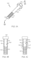
- FIG. 1A a perspective view of a coated fastener 100 constructed in accordance with an example implementation is illustrated.
- Fig. 1B is a cross-sectional view taken approximately along line 1B-1B in Fig. 1A , and shows coating layers of the coated fastener 100 in accordance with an example implementation.
- the fastener 100 has a longitudinal central axis 102.
- the fastener 100 includes a head portion 105 and a first portion 110 that is distal from the head portion 105.
- the fastener 100 may also include a second portion 120 that is disposed between the head portion 105 and the first portion 110.
- the first portion 110 of the fastener 100 may include threads (i.e., may be a threaded portion 111), while the second portion 120 of the fastener 100 may be substantially free of threads (i.e., a non-threaded portion 121), such as a shank.
- the fastener 100 includes a core body 130 ( Fig. 1B ) that comprises conductive material.
- the conductive material of the core body 130 may comprise a select one of stainless steel, nickel-based superalloy (e.g., Inconel alloy, such as Inconel 625), and titanium or titanium alloy (e.g., Ti-6A1-4V). Other types of conductive material are possible.
- the core body 130 includes the first portion 110 and the second portion 120.
- the fastener 100 also includes a first coating 140 that comprises dielectric material, such as a lubricious dielectric material.
- the dielectric material of the first coating 140 may by a coating in compliance with National Aerospace Standard NAS 4006.
- the first coating 140 may be HI-KOTE TM coating commercially available from Lisi Aerospace of Paris, France. Other types of dielectric materials are possible.
- the first coating 140 is disposed on the first portion 110 of the core body 130.
- the fastener 100 further includes a second coating 150 that comprises a conductive friction modifier material 151.
- the conductive friction modifier material 151 of the second coating 150 may comprise one of (or a combination of) graphite, a graphic alloy, and a graphic-based material.
- the graphite-based material may be graphite.
- the second coating 150 is disposed on the second portion 120 of the core body 130.
- the second coating 150 may have a coating layer thickness between about 0.1 mil to about 1 mil, wherein 1 mil equals 0.001 inch.
- the first coating 140 being disposed on the first portion 110 of the core body 130 and the second coating 150 being disposed on the second portion 120 of the core body 130
- some of the first coating 140 is also disposed on the second portion 120.
- some of the first coating 140 is also disposed on at least part 122 of the second portion 120.
- the second coating 150 is disposed on top of the some of the first coating 140 that is disposed on the at least part 122 of the second portion 120 of the core body 130.
- a number of advantages are provided by coating the fastener 100 with a combination of graphite, a graphic alloy, and a graphic-based material disclosed herein.
- One advantage is that the fastener 100 is provided with a desired transition hole fit (e.g., a light interference fit, a net fit, a slight clearance fit, a high interference fit, and clearance fit applications).
- the fastener 100 is provided with improved lubricity.
- the second coating 150 prevents bare metal of the shank (i.e., the second portion 120) of the fastener 100 from rubbing directly against hard metal (e.g., titanium) in a hole bore. The galling effects from this rubbing action is prevented or at least reduced due to the improved lubricity provided by the second coating 150.
- the fastener 100 is provided with improved electromagnetic effects protection since the second coating 150 improves conduction through the conductive material of the core body 130 of the fastener 100. The result is lower current density through the conductive material of the core body 130, and therefore less heat generated in the core body 130.
- the coating apparatus 200 includes a first device 210 for securing the fastener 100 in place to be coated.
- the first device 210 includes a spindle mechanism 212 having a spindle axis 214 that is congruent with the longitudinal central axis 102 of the fastener 100 when the fastener 100 is secured in place to be coated.
- the coating apparatus 200 also includes a second device 220 for rotating the fastener 100 about its longitudinal central axis 102.
- the second device 220 includes a drive mechanism 222 that is arranged to rotate the fastener 100 about its longitudinal central axis 102 when the conductive friction modifier material 151 is applied on the non-threaded portion 121 of the fastener 100.
- the coating apparatus 200 further includes a third device 230 for applying conductive friction modifier material 151 on the non-threaded portion 121 (i.e., the second portion 120) of the fastener 100 when the fastener 100 is secured in place to be coated and is rotated about its longitudinal central axis 102 as conductive friction modifier material 151 is being applied on the second portion 120 of the fastener 100.
- the third device 230 includes a feed mechanism 232 that is arranged to move conductive friction modifier material 151 into contact with the second portion 120 of the fastener 100 to provide the conductive friction modifier material 151 when the fastener 100 is rotated about its longitudinal central axis 102.
- a flow diagram depicts a coating method 300 for coating the fastener 100 of Fig. 1A in accordance with an example implementation.
- the fastener 100 is rotated about its longitudinal central axis 102.
- the process proceeds to block 320 in which a conductive friction modifier material 151 is applied on the second portion 120 of the fastener 100 as the fastener 100 is rotating about its longitudinal central axis 102.
- a second coating 150 that includes a graphite-based material is applied on the second portion 120 of the fastener 100 as the fastener 100 is rotating about its longitudinal central axis 102.
- a second coating 150 that includes a graphite-based material is mechanically rubbed on the second portion 120 of the fastener 100 as the fastener 100 is rotating about its longitudinal central axis 102.
- a second coating 150 that includes a graphite-based material is applied by mechanically spraying on the second portion 120 of the fastener 100 as the fastener 100 is rotating about its longitudinal central axis 102.
- the coating method further comprises securing the fastener 100 in place as the fastener 100 is rotating about its longitudinal central axis 102 and the conductive friction modifier material 151 is being applied on the second portion 120 of the fastener 100.
- a fastener made of a material from a select one of stainless steel, nickel-based superalloy (e.g., Inconel alloy, such as Inconel 625), and titanium or titanium alloy (e.g., Ti-6Al-4V) is coated according to the coating method 300.
- nickel-based superalloy e.g., Inconel alloy, such as Inconel 625
- titanium or titanium alloy e.g., Ti-6Al-4V
- the aircraft manufacturing and service method 1100 may include specification and design 1104 of the aircraft 1102 and material procurement 1106.
- component/subassembly manufacturing 1108 and system integration 1110 of the aircraft 1102 takes place.
- the aircraft 1102 may go through certification and delivery 1112 in order to be placed in service 1114.
- routine maintenance and service 1116 which may also include modification, reconfiguration, refurbishment and the like.
- a system integrator may include without limitation any number of aircraft manufacturers and major-system subcontractors; a third party may include without limitation any number of venders, subcontractors, and suppliers; and an operator may be an airline, leasing company, military entity, service organization, and so on.
- the aircraft 1102 produced by example method 1100 may include an airframe 1118 with a plurality of systems 1120 and an interior 1122.
- the plurality of systems 1120 may include one or more of a propulsion system 1124, an electrical system 1126, a hydraulic system 1128, and an environmental system 1130. Any number of other systems may be included.
- the disclosed apparatus and method may be employed during any one or more of the stages of the aircraft manufacturing and service method 1100.
- components or subassemblies corresponding to component/subassembly manufacturing 1108, system integration 1110, and/or maintenance and service 1116 may be assembled using the disclosed apparatus and method.
- the airframe 1118 may be constructed using the disclosed apparatus and method.
- one or more apparatus examples, method examples, or a combination thereof may be utilized during component/subassembly manufacturing 1108 and/or system integration 1110, for example, by substantially expediting assembly of or reducing the cost of an aircraft 1102, such as the airframe 1118 and/or the interior 1122.
- one or more apparatus examples, method examples, or a combination thereof may be utilized while the aircraft 1102 is in service, for example and without limitation, to maintenance and service 1116.
- coated fastener a fastener coating apparatus, and a fastener coating method in the aviation industry in accordance with military and space regulations
- the coated fastener, fastener coating apparatus, and fastener coating method may be implemented in any industry in accordance with the applicable industry standards.
- the specific coated fastener, fastener coating apparatus, and fastener coating method can be selected and tailored depending upon the particular application.
Landscapes
- Engineering & Computer Science (AREA)
- General Engineering & Computer Science (AREA)
- Mechanical Engineering (AREA)
- Aviation & Aerospace Engineering (AREA)
- Connection Of Plates (AREA)
Abstract
Description
- The present disclosure generally relates to fasteners, more particularly, to coated fasteners, methods and apparatuses for coating a fastener with a conductive friction modifier material, such as a graphite-based material.
- An aerospace fastener is a known type of fastener. A typical aerospace fastener is made of conductive core material that is coated with dielectric material.
- The coating of dielectric material provides the fastener with lubrication properties. The coating of dielectric material also prevents galvanic corrosion between the conductive core material of the fastener and the material to which the fastener is secured.
- In the event of an insufficient connection between the fastener and the material to which the fastener is secured, there is insufficient conduction through the conductive core material of the fastener. The result is high current density through the conductive core material, and therefore high heat generated in the fastener.
- Despite advances already made, those skilled in the art continue with research and development efforts in the field of coating fasteners including aerospace fasteners.
- Disclosed are coated fasteners.
- In one example, the disclosed coated fastener includes a core body comprising conductive material and including a first portion and a second portion. The coated fastener also includes a first coating comprising dielectric material and disposed on the first portion of the core body. The coated fastener further includes a second coating comprising a conductive friction modifier material and disposed on the second portion of the core body to provide the fastener with a desired transition hold fit, improved lubricity, and improved electromagnetic effects protection.
- Also disclosed are fastener coating methods.
- In one example, the disclosed fastener coating method includes rotating a fastener about its longitudinal central axis The fastener coating method also includes applying a conductive friction modifier material on a non-threaded portion of the fastener as the fastener is rotating about its longitudinal central axis.
- Also disclosed are coated fasteners that are made of a material from a select one of stainless steel, nickel-based superalloy (e.g., Inconel alloy, such as Inconel 625), and titanium or titanium alloy (e.g., Ti-6Al-4V), and coated according to the fastener coating method.
- Also disclosed are apparatuses for coating fasteners.
- In one example, the disclosed coating apparatus includes a first device for securing a fastener in place to be coated. The coating apparatus also includes a second device for rotating the fastener about its longitudinal central axis. The coating apparatus further includes a third device for applying a conductive friction modifier material on a non-threaded portion of the fastener when the fastener is secured in place to be coated and is rotated about its longitudinal central axis as the conductive friction modifier material is being applied on the non-threaded portion of the fastener.
- Other examples of the disclosed coated fasteners, fastener coating apparatuses, and fastener coating methods will become apparent from the following detailed description, the accompanying drawings and the appended claims.
-
-
Fig. 1A is a perspective view of a coated fastener constructed in accordance with an example implementation. -
Fig. 1B is a cross-sectional view, taken approximately alongline 1B-1B inFig. 1A , showing coating layers of the coated fastener in accordance with an example implementation. -
Fig. 1C is a cross-sectional view similar to the cross-sectional view ofFig. 1B , showing coating layers of the fastener in accordance with another example implementation. -
Fig. 2 is a schematic diagram of an apparatus for coating the fastener ofFig. 1A , and constructed in accordance with an example implementation. -
Fig. 3 is a flow diagram depicting a method for coating the fastener ofFig. 1A in accordance with an example implementation. -
Fig. 4 is a block diagram of aircraft production and service methodology. -
Fig. 5 is a schematic illustration of an aircraft. - The present application is directed to a coated fastener, a fastener coating apparatus, and a fastener coating method in a manufacturing environment, such as an aerospace part manufacturing environment. The specific construction of the fastener, apparatus, method, and the industry in which the fastener, apparatus, and method are implemented may vary. It is to be understood that the disclosure below provides a number of embodiments or examples for implementing different features of various embodiments. Specific examples of components and arrangements are described to simplify the present disclosure. These are merely examples and are not intended to be limiting.
- By way of example, the disclosure below describes a coated fastener, a fastener coating apparatus, and a fastener coating method in the manufacturing of aerospace parts. The fastener, apparatus, and method may be implemented by an original equipment manufacturer (OEM) in compliance with military and space regulations. It is conceivable that the disclosed fastener, apparatus, and method may be implemented in many other industries.
- Referring to
Fig. 1A , a perspective view of a coatedfastener 100 constructed in accordance with an example implementation is illustrated.Fig. 1B is a cross-sectional view taken approximately alongline 1B-1B inFig. 1A , and shows coating layers of the coatedfastener 100 in accordance with an example implementation. Thefastener 100 has a longitudinalcentral axis 102. - The
fastener 100 includes ahead portion 105 and afirst portion 110 that is distal from thehead portion 105. Thefastener 100 may also include asecond portion 120 that is disposed between thehead portion 105 and thefirst portion 110. Thefirst portion 110 of thefastener 100 may include threads (i.e., may be a threaded portion 111), while thesecond portion 120 of thefastener 100 may be substantially free of threads (i.e., a non-threaded portion 121), such as a shank. - The
fastener 100 includes a core body 130 (Fig. 1B ) that comprises conductive material. The conductive material of thecore body 130 may comprise a select one of stainless steel, nickel-based superalloy (e.g., Inconel alloy, such as Inconel 625), and titanium or titanium alloy (e.g., Ti-6A1-4V). Other types of conductive material are possible. Thecore body 130 includes thefirst portion 110 and thesecond portion 120. - The
fastener 100 also includes afirst coating 140 that comprises dielectric material, such as a lubricious dielectric material. The dielectric material of thefirst coating 140 may by a coating in compliance with National Aerospace Standard NAS 4006. As one specific, nonlimiting example, thefirst coating 140 may be HI-KOTE™ coating commercially available from Lisi Aerospace of Paris, France. Other types of dielectric materials are possible. Thefirst coating 140 is disposed on thefirst portion 110 of thecore body 130. - The
fastener 100 further includes asecond coating 150 that comprises a conductivefriction modifier material 151. The conductivefriction modifier material 151 of thesecond coating 150 may comprise one of (or a combination of) graphite, a graphic alloy, and a graphic-based material. As an example, the graphite-based material may be graphite. Thesecond coating 150 is disposed on thesecond portion 120 of thecore body 130. Thesecond coating 150 may have a coating layer thickness between about 0.1 mil to about 1 mil, wherein 1 mil equals 0.001 inch. - Although the above-description describes the
first coating 140 being disposed on thefirst portion 110 of thecore body 130 and thesecond coating 150 being disposed on thesecond portion 120 of thecore body 130, it is conceivable that some of thefirst coating 140 is also disposed on thesecond portion 120. For example, as shown in a region designated with circle "X" inFig. 1C , some of thefirst coating 140 is also disposed on atleast part 122 of thesecond portion 120. In the region X, thesecond coating 150 is disposed on top of the some of thefirst coating 140 that is disposed on the at leastpart 122 of thesecond portion 120 of thecore body 130. - A number of advantages are provided by coating the
fastener 100 with a combination of graphite, a graphic alloy, and a graphic-based material disclosed herein. One advantage is that thefastener 100 is provided with a desired transition hole fit (e.g., a light interference fit, a net fit, a slight clearance fit, a high interference fit, and clearance fit applications). - Another advantage is that the
fastener 100 is provided with improved lubricity. Thesecond coating 150 prevents bare metal of the shank (i.e., the second portion 120) of thefastener 100 from rubbing directly against hard metal (e.g., titanium) in a hole bore. The galling effects from this rubbing action is prevented or at least reduced due to the improved lubricity provided by thesecond coating 150. - Yet another advantage is that the
fastener 100 is provided with improved electromagnetic effects protection since thesecond coating 150 improves conduction through the conductive material of thecore body 130 of thefastener 100. The result is lower current density through the conductive material of thecore body 130, and therefore less heat generated in thecore body 130. - Referring to
Fig. 2 , a schematic diagram of acoating apparatus 200 for coating thefastener 100 ofFig. 1A , and constructed in accordance with an example implementation, is illustrated. Thecoating apparatus 200 includes afirst device 210 for securing thefastener 100 in place to be coated. Thefirst device 210 includes aspindle mechanism 212 having aspindle axis 214 that is congruent with the longitudinalcentral axis 102 of thefastener 100 when thefastener 100 is secured in place to be coated. - The
coating apparatus 200 also includes asecond device 220 for rotating thefastener 100 about its longitudinalcentral axis 102. Thesecond device 220 includes adrive mechanism 222 that is arranged to rotate thefastener 100 about its longitudinalcentral axis 102 when the conductivefriction modifier material 151 is applied on thenon-threaded portion 121 of thefastener 100. - The
coating apparatus 200 further includes athird device 230 for applying conductivefriction modifier material 151 on the non-threaded portion 121 (i.e., the second portion 120) of thefastener 100 when thefastener 100 is secured in place to be coated and is rotated about its longitudinalcentral axis 102 as conductivefriction modifier material 151 is being applied on thesecond portion 120 of thefastener 100. In particular, thethird device 230 includes afeed mechanism 232 that is arranged to move conductivefriction modifier material 151 into contact with thesecond portion 120 of thefastener 100 to provide the conductivefriction modifier material 151 when thefastener 100 is rotated about its longitudinalcentral axis 102. - Referring to
Fig. 3 , a flow diagram depicts acoating method 300 for coating thefastener 100 ofFig. 1A in accordance with an example implementation. Inblock 310, thefastener 100 is rotated about its longitudinalcentral axis 102. The process proceeds to block 320 in which a conductivefriction modifier material 151 is applied on thesecond portion 120 of thefastener 100 as thefastener 100 is rotating about its longitudinalcentral axis 102. The process then ends
In some embodiments, asecond coating 150 that includes a graphite-based material is applied on thesecond portion 120 of thefastener 100 as thefastener 100 is rotating about its longitudinalcentral axis 102. - In some embodiments, a
second coating 150 that includes a graphite-based material is mechanically rubbed on thesecond portion 120 of thefastener 100 as thefastener 100 is rotating about its longitudinalcentral axis 102. - In some embodiments, a
second coating 150 that includes a graphite-based material is applied by mechanically spraying on thesecond portion 120 of thefastener 100 as thefastener 100 is rotating about its longitudinalcentral axis 102. - In some embodiments, the coating method further comprises securing the
fastener 100 in place as thefastener 100 is rotating about its longitudinalcentral axis 102 and the conductivefriction modifier material 151 is being applied on thesecond portion 120 of thefastener 100. - In some embodiments, a fastener made of a material from a select one of stainless steel, nickel-based superalloy (e.g., Inconel alloy, such as Inconel 625), and titanium or titanium alloy (e.g., Ti-6Al-4V) is coated according to the
coating method 300. - Examples of the disclosure may be described in the context of an aircraft manufacturing and
service method 1100, as shown inFig. 4 , and anaircraft 1102, as shown inFig. 5 . During pre-production, the aircraft manufacturing andservice method 1100 may include specification anddesign 1104 of theaircraft 1102 andmaterial procurement 1106. During production, component/subassembly manufacturing 1108 andsystem integration 1110 of theaircraft 1102 takes place. Thereafter, theaircraft 1102 may go through certification anddelivery 1112 in order to be placed inservice 1114. While in service by a customer, theaircraft 1102 is scheduled for routine maintenance andservice 1116, which may also include modification, reconfiguration, refurbishment and the like. - Each of the processes of
method 1100 may be performed or carried out by a system integrator, a third party, and/or an operator (e.g., a customer). For the purposes of this description, a system integrator may include without limitation any number of aircraft manufacturers and major-system subcontractors; a third party may include without limitation any number of venders, subcontractors, and suppliers; and an operator may be an airline, leasing company, military entity, service organization, and so on. - As shown in
Fig. 5 , theaircraft 1102 produced byexample method 1100 may include anairframe 1118 with a plurality ofsystems 1120 and an interior 1122. Examples of the plurality ofsystems 1120 may include one or more of apropulsion system 1124, anelectrical system 1126, ahydraulic system 1128, and anenvironmental system 1130. Any number of other systems may be included. - The disclosed apparatus and method may be employed during any one or more of the stages of the aircraft manufacturing and
service method 1100. As one example, components or subassemblies corresponding to component/subassembly manufacturing 1108,system integration 1110, and/or maintenance andservice 1116 may be assembled using the disclosed apparatus and method. As another example, theairframe 1118 may be constructed using the disclosed apparatus and method. Also, one or more apparatus examples, method examples, or a combination thereof may be utilized during component/subassembly manufacturing 1108 and/orsystem integration 1110, for example, by substantially expediting assembly of or reducing the cost of anaircraft 1102, such as theairframe 1118 and/or the interior 1122. Similarly, one or more apparatus examples, method examples, or a combination thereof may be utilized while theaircraft 1102 is in service, for example and without limitation, to maintenance andservice 1116. - The disclosure also includes the following clauses:
- Clause 1. A coated fastener comprising:
- a core body comprising conductive material and including a first portion and a second portion;
- a first coating comprising dielectric material and disposed on the first portion of the core body; and
- a second coating comprising a conductive friction modifier material and disposed on the second portion of the core body to provide the fastener with a desired transition hold fit, improved lubricity, and improved electromagnetic effects protection.
- Clause 2. The coated fastener of clause 1 wherein (i) the first portion of the core body comprises a threaded portion, and (ii) the second portion of the core body comprises a non-threaded portion.
- Clause 3. The coated fastener of clause 2 wherein the non-threaded portion of the core body comprises a shank of the fastener.
- Clause 4. The coated fastener of any of clauses 1 to 3, wherein the conductive material of the core body comprises a select one of stainless steel, nickel-based superalloy, and titanium alloy.
- Clause 5. The coated fastener of clause 4 wherein the conductive friction modifier material of the second coating comprises at least one of graphite, a graphic alloy, and a graphic-based material.
- Clause 6. The coated fastener of clause 4 or clause 5, wherein the dielectric material of the first coating comprises graphite.
- Clause 7. The coated fastener of any of clauses 1 to 6 wherein (i) some of the first coating is also disposed on at least part of the second portion of the core body, and (ii) the second coating is disposed on top of the some of the first coating that is disposed on the at least part of the second portion of the core body.
- Clause 8. The coated fastener of any of clauses 1 to 7 wherein the second coating has a coating layer thickness between about 0.1 mil and about 1 mil.
- Clause 9. A coating method for a fastener having a longitudinal central axis and a non-threaded portion, the coating method comprising:
- rotating the fastener about its longitudinal central axis; and
- applying a conductive friction modifier material onto the non-threaded portion of the fastener as the fastener is rotating about its longitudinal central axis.
- Clause 10. The coating method of clause 9 wherein applying the conductive friction modifier material on the non-threaded portion of the fastener as the fastener is rotating about its longitudinal central axis comprises:
applying a graphite-based material onto the non-threaded portion of the fastener as the fastener is rotating about its longitudinal central axis. - Clause 11. The coating method of clause 9 or clause 10 wherein applying a conductive friction modifier material on the non-threaded portion of the fastener as the fastener is rotating about its longitudinal central axis comprises:
mechanically rubbing a graphite-based material onto the non-threaded portion of the fastener as the fastener is rotating about its longitudinal central axis. - Clause 12. The coating method of clause 9 or clause 10 wherein applying a conductive friction modifier material on the non-threaded portion of the fastener as the fastener is rotating about its longitudinal central axis comprises:
mechanically spraying a graphite-based material onto the non-threaded portion of the fastener as the fastener is rotating about its longitudinal central axis. - Clause 13. The coating method of any of clauses 9 to 12 further comprising:
securing the fastener in place as the fastener is rotating about its longitudinal central axis and the conductive friction modifier material is being applied on the non-threaded portion of the fastener. - Clause 14. A coated fastener made of a material from a select one of stainless steel, nickel-based superalloy, and titanium alloy, and coated according to the coating method of any of clauses 9 to 13.
- Clause 15. A coating apparatus for a fastener having a longitudinal central axis and a non-threaded portion, the coating apparatus comprising:
- a first device for securing the fastener in place to be coated;
- a second device for rotating the fastener about its longitudinal central axis; and
- a third device for applying a conductive friction modifier material on the non-threaded portion of the fastener when the fastener is secured in place to be coated and is rotated about its longitudinal central axis as the conductive friction modifier material is being applied on the non-threaded portion of the fastener.
- Clause 16. The coating apparatus of clause 15 wherein the first device comprises a spindle mechanism having a spindle axis that is congruent with the longitudinal central axis of the fastener when the fastener is secured in place to be coated.
- Clause 17. The coating apparatus of clause 15 or clause 16 wherein the second device comprises a drive mechanism that is arranged to rotate the fastener about its longitudinal central axis when the conductive friction modifier material is applied on the non-threaded portion of the fastener.
- Clause 18. The coating apparatus of any of clauses 15 to 17 wherein the third device comprises a feed mechanism that is arranged to move conductive friction modifier material into contact with the non-threaded portion of the fastener to provide the conductive friction modifier material when the fastener is rotated about its longitudinal central axis.
- Clause 19. The coating apparatus of any of clauses 15 to 18 wherein the conductive friction modifier material comprises a graphite-based material.
- Clause 20. The coating apparatus of clause 19 wherein the graphite-based material is graphite.
- Clause 21. The coating apparatus of any of clauses 15 to 20 configured to perform the method of any of clauses 9 to 14.
- Clause 22. A coated fastener made using the coating apparatus of any of clauses 15 to 21.
- Clause 23. The coated fastener of any of clauses 1 to 8 made using the method of any of clauses 9 to 14 or the coating apparatus of clauses 15 to 21.
- Different examples of the apparatus and method disclosed herein include a variety of components, features, and functionalities. It should be understood that the various examples of the apparatus and method disclosed herein may include any of the components, features, and functionalities of any of the other examples of the apparatus and method disclosed herein in any combination, and all of such possibilities are intended to be within the scope of the present disclosure.
- The above-described apparatus and method are described in the context of an aircraft. However, one of ordinary skill in the art will readily recognize that the disclosed apparatus and method are suitable for a variety of applications, and the present disclosure is not limited to aircraft manufacturing applications. For example, the disclosed apparatus and method may be implemented in various types of vehicles including, for example, helicopters, passenger ships, automobiles, marine products (boat, motors, etc.) and the like. Non-vehicle applications are also contemplated.
- Although the above-description describes a coated fastener, a fastener coating apparatus, and a fastener coating method in the aviation industry in accordance with military and space regulations, it is contemplated that the coated fastener, fastener coating apparatus, and fastener coating method may be implemented in any industry in accordance with the applicable industry standards. The specific coated fastener, fastener coating apparatus, and fastener coating method can be selected and tailored depending upon the particular application.
- Further, although various examples of disclosed embodiments have been shown and described, modifications may occur to those skilled in the art upon reading the specification. The present application includes such modifications and is limited only by the scope of the claims.
Claims (15)
- A coated fastener (100) comprising:a core body (130) comprising conductive material and including a first portion (110) and a second portion (120);a first coating (140) comprising dielectric material and disposed on the first portion (110) of the core body (130); anda second coating (150) comprising a conductive friction modifier material (151) and disposed on the second portion (120) of the core body (130).
- The coated fastener (100) of claim 1 wherein (i) the first portion (110) of the core body (130) comprises a threaded portion (111), and (ii) the second portion (120) of the core body (130) comprises a non-threaded portion (121).
- The coated fastener (100) of claim 2 wherein the non-threaded portion (121) of the core body (130) comprises a shank of the fastener (100).
- The coated fastener (100) of any preceding claim wherein at least one of:the conductive material of the core body (130) comprises a select one of stainless steel, nickel-based superalloy, and titanium alloy;the conductive friction modifier material (151) of the second coating (150) comprises at least one of graphite, a graphic alloy, and a graphic-based material; andthe dielectric material of the first coating (140) comprises graphite.
- The coated fastener (100) of any preceding claim, wherein (i) some of the first coating (140) is also disposed on at least part (122) of the second portion (120) of the core body (130), and (ii) the second coating (150) is disposed on top of the some of the first coating (140) that is disposed on the at least part (122) of the second portion (120) of the core body (130).
- The coated fastener (100) of any preceding claim, wherein the second coating (150) has a coating layer thickness between about 0.1 mil and about 1 mil.
- A coating method (300) for a fastener (100) having a longitudinal central axis (102) and a non-threaded portion (121), the coating method (300) comprising:rotating (310) the fastener (100) about its longitudinal central axis (102); andapplying (320) a conductive friction modifier material (151) onto the non-threaded portion (121) of the fastener (100) as the fastener (100) is rotating about its longitudinal central axis (102).
- The coating method (300) of claim 7 wherein applying the conductive friction modifier material (151) on the non-threaded portion (121) of the fastener (100) as the fastener (100) is rotating about its longitudinal central axis (102) comprises one of:applying a graphite-based material onto the non-threaded portion (121) of the fastener (100) as the fastener (100) is rotating about its longitudinal central axis (102);mechanically rubbing a graphite-based material onto the non-threaded portion (121) of the fastener (100) as the fastener (100) is rotating about its longitudinal central axis (102); andmechanically spraying a graphite-based material onto the non-threaded portion (121) of the fastener (100) as the fastener (100) is rotating about its longitudinal central axis (102).
- The coating method (300) of claim 7 or claim 8 further comprising:
securing the fastener (100) in place as the fastener (100) is rotating about its longitudinal central axis (102) and the conductive friction modifier material (151) is being applied on the non-threaded portion (121) of the fastener (100). - A coated fastener (100) made of a material from a select one of stainless steel, nickel-based superalloy, and titanium alloy, and coated according to the coating method (300) of any of claims 7 to 9.
- A coating apparatus (200) for a fastener (100) having a longitudinal central axis (102) and a non-threaded portion (121), the coating apparatus (200) comprising:a first device (210) for securing the fastener (100) in place to be coated;a second device (220) for rotating the fastener (100) about its longitudinal central axis (102); anda third device (230) for applying a conductive friction modifier material (151) on the non-threaded portion (121) of the fastener (100) when the fastener (100) is secured in place to be coated and is rotated about its longitudinal central axis (102) as the conductive friction modifier material (151) is being applied on the non-threaded portion (121) of the fastener (100).
- The coating apparatus (200) of claim 11 wherein the first device (210) comprises a spindle mechanism (212) having a spindle axis (214) that is congruent with the longitudinal central axis (102) of the fastener (100) when the fastener (100) is secured in place to be coated.
- The coating apparatus (200) of claim 11 or claim 12 wherein the second device (220) comprises a drive mechanism (222) that is arranged to rotate the fastener (100) about its longitudinal central axis (102) when the conductive friction modifier material (151) is applied on the non-threaded portion (121) of the fastener (100).
- The coating apparatus (200) of any of claims 11 to 13 wherein the third device (230) comprises a feed mechanism (232) that is arranged to move conductive friction modifier material (151) into contact with the non-threaded portion (121) of the fastener (100) to provide the conductive friction modifier material (151) when the fastener (100) is rotated about its longitudinal central axis (102).
- The coating apparatus (200) of any of claims 11 to 14 wherein the conductive friction modifier material (151) comprises a graphite-based material.
Applications Claiming Priority (1)
| Application Number | Priority Date | Filing Date | Title |
|---|---|---|---|
| US18/326,179 US20240401630A1 (en) | 2023-05-31 | 2023-05-31 | Coated fastener and coating method and apparatus therefor |
Publications (1)
| Publication Number | Publication Date |
|---|---|
| EP4471281A1 true EP4471281A1 (en) | 2024-12-04 |
Family
ID=91073224
Family Applications (1)
| Application Number | Title | Priority Date | Filing Date |
|---|---|---|---|
| EP24175245.0A Pending EP4471281A1 (en) | 2023-05-31 | 2024-05-10 | Coated fastener and coating method and apparatus therefor |
Country Status (2)
| Country | Link |
|---|---|
| US (1) | US20240401630A1 (en) |
| EP (1) | EP4471281A1 (en) |
Citations (4)
| Publication number | Priority date | Publication date | Assignee | Title |
|---|---|---|---|---|
| US4842890A (en) * | 1987-07-07 | 1989-06-27 | Nylok Fastener Corporation | Method for coating fasteners |
| WO2006110756A1 (en) * | 2005-04-11 | 2006-10-19 | Elisha Holding Llc | Corrosion resistant article and method of production thereof |
| WO2014069393A1 (en) * | 2012-10-30 | 2014-05-08 | 三菱重工業株式会社 | Seal application device and seal application method |
| US10544815B2 (en) * | 2014-09-30 | 2020-01-28 | Lisi Aerospace | Fastener using lubricated interference fit |
Family Cites Families (13)
| Publication number | Priority date | Publication date | Assignee | Title |
|---|---|---|---|---|
| DE19916860A1 (en) * | 1998-04-28 | 1999-11-04 | Mcgard Inc | Fastening element for fitting wheel to motor vehicle |
| EP1712659A1 (en) * | 2005-04-11 | 2006-10-18 | Elisha Holding LLC | Corrosion resistant article and method of production thereof |
| US8382413B2 (en) * | 2008-11-17 | 2013-02-26 | The Boeing Company | Conductive sleeved fastener assembly |
| KR101420155B1 (en) * | 2009-10-22 | 2014-07-16 | 알코아 인코포레이티드 | Enhanced conductivity sleeved fastener and method for making same |
| US9331402B2 (en) * | 2013-02-04 | 2016-05-03 | The Boeing Company | Conductive sleeved fastener assembly |
| FR3008754B1 (en) * | 2013-07-19 | 2015-09-04 | Lisi Aerospace | METAL FASTENING |
| FR3013781A1 (en) * | 2013-11-25 | 2015-05-29 | Airbus Operations Sas | FIXING ELEMENT FOR PARTS OF AN ASSEMBLY |
| US9908637B2 (en) * | 2014-05-23 | 2018-03-06 | The Boeing Company | Modified shank fasteners for electromagnetic effect (EME) technology |
| EP3194799A1 (en) * | 2014-09-17 | 2017-07-26 | Arconic Inc. | Fasteners with dual skin depth washers |
| US9939004B2 (en) * | 2014-09-17 | 2018-04-10 | Arconic Inc | Coated fasteners with conforming seals |
| US11365757B2 (en) * | 2016-08-12 | 2022-06-21 | Lisi Aerospace | Fastener with lubricating ring for interference fitting, and assembly method using such a fastener |
| US11137014B2 (en) * | 2019-01-08 | 2021-10-05 | The Boeing Company | Conductive fastening system and method for improved EME performance |
| US20200291979A1 (en) * | 2019-03-15 | 2020-09-17 | Roller Bearing Company Of America, Inc. | Bolt interface coating and thread transition geometry for sleeved fasteners used in composite applications |
-
2023
- 2023-05-31 US US18/326,179 patent/US20240401630A1/en active Pending
-
2024
- 2024-05-10 EP EP24175245.0A patent/EP4471281A1/en active Pending
Patent Citations (4)
| Publication number | Priority date | Publication date | Assignee | Title |
|---|---|---|---|---|
| US4842890A (en) * | 1987-07-07 | 1989-06-27 | Nylok Fastener Corporation | Method for coating fasteners |
| WO2006110756A1 (en) * | 2005-04-11 | 2006-10-19 | Elisha Holding Llc | Corrosion resistant article and method of production thereof |
| WO2014069393A1 (en) * | 2012-10-30 | 2014-05-08 | 三菱重工業株式会社 | Seal application device and seal application method |
| US10544815B2 (en) * | 2014-09-30 | 2020-01-28 | Lisi Aerospace | Fastener using lubricated interference fit |
Also Published As
| Publication number | Publication date |
|---|---|
| US20240401630A1 (en) | 2024-12-05 |
Similar Documents
| Publication | Publication Date | Title |
|---|---|---|
| US9003650B2 (en) | Conductive sleeved fastener assembly | |
| KR102285190B1 (en) | Modified shank fasteners for electromagnetic effect (eme) technology | |
| EP3260708A1 (en) | Fluid-tight mechanical fastening system and associated structural assembly | |
| EP2390514A1 (en) | Method for fastening aircraft components using a composite two-piece fastening system, and so obtained aircraft structure | |
| AU2016204482A1 (en) | Methods for diverting lightning current from skin fasteners in composite, non-metallic structures | |
| JP6534865B2 (en) | Method and apparatus for containing a spark in a fuel tank | |
| EP3218529A2 (en) | Masking plug for cold spray repair at counterbore hole | |
| US11293474B2 (en) | Fasteners having enhanced electrical energy dispersion properties | |
| US20240401630A1 (en) | Coated fastener and coating method and apparatus therefor | |
| EP3296365A1 (en) | Method for promoting electrical conduction between metallic components and composite materials | |
| Champagne Jr et al. | Cold spray applications | |
| US20180148194A1 (en) | Enhanced tooling for interference-fit fasteners | |
| US20210180636A1 (en) | Mechanical fastener system for electromagnetic effect (eme) protection | |
| EP3550161B1 (en) | Fasteners having enhanced electrical energy dispersion properties | |
| EP4495436B1 (en) | Fastener systems and methods for joining multiple substrates of workpiece | |
| US20250027520A1 (en) | Fastener systems and methods for joining multiple substrates of workpiece | |
| US20250010333A1 (en) | Applicator tools, methods and systems for coating a bore | |
| Evans | The influence of secondary bending on fatigue life improvement in bolted joints | |
| Lemke | Aerospace/Wline Plating & Metal Rimishing kw8adkE. 3cpo | |
| GLIDE et al. | REFRACTORY METAL COATING SYSTEMS | |
| Gentsch et al. | A Profile of Defense Manufacturing Costs and Enabling Technologies | |
| Fitzgerald et al. | Material and Process Considerations for Developing and Qualifying Repair Coatings for Nickel/Chrome Replacement |
Legal Events
| Date | Code | Title | Description |
|---|---|---|---|
| PUAI | Public reference made under article 153(3) epc to a published international application that has entered the european phase |
Free format text: ORIGINAL CODE: 0009012 |
|
| STAA | Information on the status of an ep patent application or granted ep patent |
Free format text: STATUS: THE APPLICATION HAS BEEN PUBLISHED |
|
| AK | Designated contracting states |
Kind code of ref document: A1 Designated state(s): AL AT BE BG CH CY CZ DE DK EE ES FI FR GB GR HR HU IE IS IT LI LT LU LV MC ME MK MT NL NO PL PT RO RS SE SI SK SM TR |
|
| STAA | Information on the status of an ep patent application or granted ep patent |
Free format text: STATUS: REQUEST FOR EXAMINATION WAS MADE |
|
| 17P | Request for examination filed |
Effective date: 20250327 |
|
| STAA | Information on the status of an ep patent application or granted ep patent |
Free format text: STATUS: EXAMINATION IS IN PROGRESS |
|
| 17Q | First examination report despatched |
Effective date: 20260223 |