EP4471279A1 - Reversible fastening mechanism for quick and reversible fixing - Google Patents
Reversible fastening mechanism for quick and reversible fixing Download PDFInfo
- Publication number
- EP4471279A1 EP4471279A1 EP24179548.3A EP24179548A EP4471279A1 EP 4471279 A1 EP4471279 A1 EP 4471279A1 EP 24179548 A EP24179548 A EP 24179548A EP 4471279 A1 EP4471279 A1 EP 4471279A1
- Authority
- EP
- European Patent Office
- Prior art keywords
- internal
- key
- external
- internal element
- fastening mechanism
- Prior art date
- Legal status (The legal status is an assumption and is not a legal conclusion. Google has not performed a legal analysis and makes no representation as to the accuracy of the status listed.)
- Granted
Links
Images



Classifications
-
- F—MECHANICAL ENGINEERING; LIGHTING; HEATING; WEAPONS; BLASTING
- F16—ENGINEERING ELEMENTS AND UNITS; GENERAL MEASURES FOR PRODUCING AND MAINTAINING EFFECTIVE FUNCTIONING OF MACHINES OR INSTALLATIONS; THERMAL INSULATION IN GENERAL
- F16B—DEVICES FOR FASTENING OR SECURING CONSTRUCTIONAL ELEMENTS OR MACHINE PARTS TOGETHER, e.g. NAILS, BOLTS, CIRCLIPS, CLAMPS, CLIPS OR WEDGES; JOINTS OR JOINTING
- F16B3/00—Key-type connections; Keys
-
- A—HUMAN NECESSITIES
- A61—MEDICAL OR VETERINARY SCIENCE; HYGIENE
- A61B—DIAGNOSIS; SURGERY; IDENTIFICATION
- A61B17/00—Surgical instruments, devices or methods
- A61B17/56—Surgical instruments or methods for treatment of bones or joints; Devices specially adapted therefor
- A61B17/58—Surgical instruments or methods for treatment of bones or joints; Devices specially adapted therefor for osteosynthesis, e.g. bone plates, screws or setting implements
- A61B17/68—Internal fixation devices, including fasteners and spinal fixators, even if a part thereof projects from the skin
- A61B17/84—Fasteners therefor or fasteners being internal fixation devices
- A61B17/86—Pins or screws or threaded wires; nuts therefor
Definitions
- the present invention refers to the field of the mechanisms for fastening two or more structures, in a temporary or permanent manner.
- Fastening mechanisms are used to join, temporarily or permanently, two or more structures to each other.
- a fastening mechanism must be selected based on:
- screws The most commonly used mechanical fastening devices are screws.
- the proposed invention innovatively provides a solution for such problem.
- a reversible fastening mechanism comprising an internal element (1), an external element (2) and a key (3)
- the internal element (1) comprises a central cavity having a bottom wall, at least one spring (9) connected to said bottom wall and projecting to said cavity, and at least one stationary stop (7) positioned within said cavity
- the external element (2) comprises a central hole, and at least one stationary stop (7) positioned within said central hole
- the key (3) comprises an internal portion and an external portion (6), having said internal portion at least one internal lock (4) and at least one external lock (5); in which the internal element (1) is positioned adjacently to the external element (2) so that the central hole of the external element (2) is aligned with the central cavity of the internal element (1);
- the internal portion of the key (3) is configured to be inserted through the central hole of the external element (2) and through the central cavity of the internal element (1) to engage the spring (9) of the internal element (1);
- the external portion (6) of the key (3) is configured to allow a rotation movement of the key (3) so that the internal lock (4)
- the present invention concerns a quick and reversible fastening mechanism in which the internal element (1) and external element (2) are each installed in one of the structures to be joined, and a key (3), which ensures the rapid and precise fixation and release of these structures.
- the internal element (1) and external element (2) are each one connected to a given structure that need to be fixed to one another, wherein the positional alignment of the internal element (1) with the external element (2) provide temporary contacts which are then secured using the key (3), which is inserted through the central hole and central cavity with minimal resistance and by rotating the external portion (6) of the key (3) allows the internal portion of the key (3) to rotate as well so that the internal lock (4) and external lock (5) may engage and be secured to the stationary stop (7)s of the internal element (1) and external element (2), respectively.
- the spring (9) engages with the internal portion of the key (3), as it is inserted in the cavity of the internal element (1), thus exerting a constant force in the opposite direction, thereby pushing the internal lock (4) and external lock (5) against the stationary stop (7)s of the internal element (1) and of the external element (2), respectively, thus increasing the stability of the connection while also providing great speed to the fixing operations.
- the rotation of the external portion (6) of the key (3) in the opposite direction will quickly release the internal element (1) and external element (2) from the key (3).
- the mechanism is robust and allows repeated fixing and releasing operations while minimizing the deterioration of the mechanical elements involved in the connection.
- Each reversible fastening mechanism can be manufactured according to the dimensional characteristics and materials that make up the structures to be joined, such as their dimensions (height, width and thickness), the physical, chemical and environmental stresses to which these structures will be predictably subject during their useful life, taking into account their mechanical resistance to rupture and/or their structural resistance to deformation and corrosion.
- the main advantages of the object of the present invention are the quick and reversible mechanical fixing mechanism which is indicated for use in projects where the quickest and most precise fixation and release of structures or components is relevant, repeatedly or not, whether in processes of current use, whether for packaging or transport, or in maintenance and/or repair task; a greater flexibility in terms of the design, manufacture, functionality, logistics and maintenance of structures to use; and greater efficiency (increased safety, speed and precision) of the fixing and releasing processes of these structures.
- the reversible fastening mechanism may be applicable in the automotive and other vehicle construction industries, in the aerospace industry, in the naval industry and in any other technical equipment subject to frequent maintenance, therefore may have several configurations and is not limited to any of its described embodiments.
- the internal element (1) further comprises at least one fitting component (8) connected to the spring (9) and at least one peripheral fitting component (10); and the external element (2) comprises at least one peripheral fitting slot (12), so that the fitting component (8) connected to the spring (9) of the internal element (1) is adapted to engage the internal portion of the key (3) when the key (3) is fully inserted into the cavity of the internal element (1).
- the peripheral fitting component (10) of the internal element (1) is configured to engage with the peripheral fitting slot (12) of the external element (2), thereby increasing the precision during the positioning and alignment of the internal element (1) and of the external element (2), prior to the insertion of the key (3).
- Another advantage is that the engagement between the peripheral fitting component (10) of the internal element (1) and the peripheral fitting slot (12) of the external element (2) does not interfere with the relative displacement of the internal element (1), external element (2) and key (3) to be fixed, either in the approach movement for fixing, or in the movement away to release the structures.
- the internal element (1) further comprises at least one peripheral cavity having a bottom wall to which a spring (11) is connected, being said spring (11) also connected to the peripheral fitting component (10), so that the spring (11) provides constant pressure upon the engagement between the peripheral fitting component (10) of the internal element (1) and the peripheral fitting slot (12) of the external element (2).
- the constant force exerted of the peripheral springs (11) promotes the engagement of the peripheral fitting component (10) of the internal element (1) with the peripheral fitting slot (12) of the external element (2), thereby increasing the stability of the assembly and also contributing to the stable engagement of the stationary stop (7)s of the internal element (1) and external element (2) with the internal and external locks (5) of the key (3).
- peripheral springs (11) Another advantage of the peripheral springs (11) is the increase of the speed of assembly, wherein the peripheral fitting components (10) are easily driven towards the corresponding fitting slot by the natural expansion tendency of a spring (11) being compressed when the internal element (1) and the external element (2) are positioned closer together and aligned, prior to the insertion of the key (3).
- the bottom wall of the central cavity and the bottom wall of the peripheral cavity of the internal element (1) each comprise a removable cap (16).
- the advantage to have the bottom of the central cavity is that it facilitates the access to the cavity of the internal element (1) in order to perform maintenance operations, such as repairing of the central spring (9) or of the fitting component (8), or even replacement of the central spring (9) or fitting component (8).
- the peripheral cavity of the internal element (1) may also comprise a removable cap (16) to allow maintenance operations to repair or replace the peripheral springs (11), if necessary.
- the internal element (1) of the reversible fastening mechanism may comprise at least two peripheral fitting components (10), each one configured to engage with one peripheral fitting slot (12) of the external element (2).
- the internal element (1) of the reversible fastening mechanism may comprise at least two peripheral cavities, each peripheral cavity having a bottom wall and comprising one spring (11) connected to one peripheral fitting component (10), wherein the bottom wall of each peripheral cavity of the internal element (1) may comprise a removable cap (16).
- the shape of the fitting component (8) and the shape of the peripheral fitting components (10) is semispherical, in which the peripheral fitting slot (12) of the external element (2) may have a complementary shape to the semispherical peripheral fitting component (10) of the internal element (1), thereby increasing the stability of the connection.
- the internal portion of the key (3) may comprise a fitting slot adapted to engage with the fitting component (8) connected to the spring (9) of the central cavity, having said fitting slot a complementary shape to the semispherical fitting component (8) of the internal element (1).
- the external portion (6) of the key (3) comprises at least two cavities, each cavity comprising a bottom wall and at least one spring (14) attached to said bottom wall and to a button cap (13).
- the advantage of the cavities comprised in the external portion (6) of the key (3) is to improve the grip to facilitate the rotation of the key (3), by having two button cap (13)s which collapse into the cavity, allowing the user to grip the inside walls of the cavities of the external portion (6) of the key (3) to manipulate the key (3).
- each button cap (13) covers the cavity completely and is leveled with the surface of the external portion (6) of the key (3), being each button cap (13) configured to allow being pushed inside a cavity against the force exerted by the spring (14), in which the button cap (13) returns to a leveled position with the surface of the external portion (6) of the key (3) in the absence of forces applied to the button cap (13).
- the aerodynamic performance or the reversible fastening mechanism is improved while maintaining the functionality of improving the grip of the external portion (6) of the key (3) to improve the handling of the key (3), thus allowing the application of the reversible fastening mechanism to minimalistic structures or systems in which aerodynamic performance is important.
- the internal element (1) and the external element (2) each comprise one peripheral frame structure (17), being said peripheral frame structure (17) connected to the lateral surface of the internal element (1) and/or the lateral surface of the external element (2).
- peripheral frame structure (17) to the internal element (1) and external element (2) allows a more precise and stable application of the reversible fastening mechanism into structures made of composite materials, in which two composite materials can be fixed together by first being connected to each peripheral frame structure (17) to then be secured by the engagement between the internal element (1), external element (2) and the key (3).
- the peripheral frame structure (17) is positioned along a perpendicular plane to insertion position of the key (3).
- the internal portion and the external portion (6) of the key (3) preferably comprise a cylindrical shaft.
- the reversible fastening mechanism may be manufactured using several materials, such as metals, hard plastics, wood and composite materials.
- the method to use the reversible fastening mechanism comprise the following steps:
Landscapes
- Health & Medical Sciences (AREA)
- Engineering & Computer Science (AREA)
- Orthopedic Medicine & Surgery (AREA)
- General Engineering & Computer Science (AREA)
- Surgery (AREA)
- Life Sciences & Earth Sciences (AREA)
- Heart & Thoracic Surgery (AREA)
- Biomedical Technology (AREA)
- Nuclear Medicine, Radiotherapy & Molecular Imaging (AREA)
- Medical Informatics (AREA)
- Molecular Biology (AREA)
- Animal Behavior & Ethology (AREA)
- General Health & Medical Sciences (AREA)
- Public Health (AREA)
- Veterinary Medicine (AREA)
- Neurology (AREA)
- Mechanical Engineering (AREA)
- Connection Of Plates (AREA)
- Snaps, Bayonet Connections, Set Pins, And Snap Rings (AREA)
Abstract
Description
- The present invention refers to the field of the mechanisms for fastening two or more structures, in a temporary or permanent manner.
- Fastening mechanisms are used to join, temporarily or permanently, two or more structures to each other.
- When permanent fixation of structures is desired, we can opt for a mechanical device or a chemical union, using adhesive substances such as glues, or by welding, if applicable. For temporary connections, the fastening mechanisms to be used must be mechanical to allow repeated fastening and releasing procedures.
- In any project, a fastening mechanism must be selected based on:
- the characteristics of the structures or technical device under design;
- the mechanical properties of the materials that make up the structures to be joined;
- the physical, chemical and environmental stresses to which the structures and the fixing device will be subjected, during the useful life of the structures or technical device under design.
- The most commonly used mechanical fastening devices are screws. The use of screws, or sets of screws and nuts properly selected and suitable for a given project, allows for relatively quick, effective and long-lasting fixation.
- However, in a temporary, reversible fixation that may be repetitive, this type of fixation is not suitable, due to the rapid deterioration of the support material in each repetition of the fastening and/or removal process, and the time it takes to fasten and/or remove these devices.
- The proposed invention innovatively provides a solution for such problem.
- It is an object of the present invention a reversible fastening mechanism comprising an internal element (1), an external element (2) and a key (3), wherein the internal element (1) comprises a central cavity having a bottom wall, at least one spring (9) connected to said bottom wall and projecting to said cavity, and at least one stationary stop (7) positioned within said cavity; the external element (2) comprises a central hole, and at least one stationary stop (7) positioned within said central hole; the key (3) comprises an internal portion and an external portion (6), having said internal portion at least one internal lock (4) and at least one external lock (5); in which the internal element (1) is positioned adjacently to the external element (2) so that the central hole of the external element (2) is aligned with the central cavity of the internal element (1); the internal portion of the key (3) is configured to be inserted through the central hole of the external element (2) and through the central cavity of the internal element (1) to engage the spring (9) of the internal element (1); the external portion (6) of the key (3) is configured to allow a rotation movement of the key (3) so that the internal lock (4) of the key (3) engages the stationary stop (7) of the internal element (1) and the external lock (5) of the key (3) engages the stationary stop (7) of the external element (2).
- The present invention concerns a quick and reversible fastening mechanism in which the internal element (1) and external element (2) are each installed in one of the structures to be joined, and a key (3), which ensures the rapid and precise fixation and release of these structures.
- In a preferred aspect of the present invention, the internal element (1) and external element (2) are each one connected to a given structure that need to be fixed to one another, wherein the positional alignment of the internal element (1) with the external element (2) provide temporary contacts which are then secured using the key (3), which is inserted through the central hole and central cavity with minimal resistance and by rotating the external portion (6) of the key (3) allows the internal portion of the key (3) to rotate as well so that the internal lock (4) and external lock (5) may engage and be secured to the stationary stop (7)s of the internal element (1) and external element (2), respectively.
- In addition, the spring (9) engages with the internal portion of the key (3), as it is inserted in the cavity of the internal element (1), thus exerting a constant force in the opposite direction, thereby pushing the internal lock (4) and external lock (5) against the stationary stop (7)s of the internal element (1) and of the external element (2), respectively, thus increasing the stability of the connection while also providing great speed to the fixing operations. In addition, if there is a need to quickly disrupt the connection, the rotation of the external portion (6) of the key (3) in the opposite direction will quickly release the internal element (1) and external element (2) from the key (3). At the same time, the mechanism is robust and allows repeated fixing and releasing operations while minimizing the deterioration of the mechanical elements involved in the connection.
- Each reversible fastening mechanism can be manufactured according to the dimensional characteristics and materials that make up the structures to be joined, such as their dimensions (height, width and thickness), the physical, chemical and environmental stresses to which these structures will be predictably subject during their useful life, taking into account their mechanical resistance to rupture and/or their structural resistance to deformation and corrosion.
- The main advantages of the object of the present invention are the quick and reversible mechanical fixing mechanism which is indicated for use in projects where the quickest and most precise fixation and release of structures or components is relevant, repeatedly or not, whether in processes of current use, whether for packaging or transport, or in maintenance and/or repair task; a greater flexibility in terms of the design, manufacture, functionality, logistics and maintenance of structures to use; and greater efficiency (increased safety, speed and precision) of the fixing and releasing processes of these structures.
- The reversible fastening mechanism may be applicable in the automotive and other vehicle construction industries, in the aerospace industry, in the naval industry and in any other technical equipment subject to frequent maintenance, therefore may have several configurations and is not limited to any of its described embodiments.
-
-
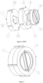
Figure 1 illustrates an exploded view from the exterior side of a preferred embodiment of the reversible fastening mechanism. -
Figure 2 illustrates a perspective view from the exterior side of a preferred embodiment of the reversible fastening mechanism in an assembled configuration. -
Figure 3 illustrates an exploded view from the interior side of a preferred embodiment of the reversible fastening mechanism. -
Figure 4 illustrates a perspective view from the interior side of a preferred embodiment of the reversible fastening mechanism in an assembled configuration. -
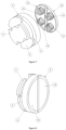
Figure 5 illustrates an exploded view from the interior side of the internal element (1) of the reversible fastening mechanism. -
Figure 6 illustrates the interior side of the removable cap (15) with a central spring (9) (9). -
Figure 7 illustrates an exploded view from the interior side of the key (3) of the reversible fastening mechanism. -
Figure 8 illustrates a perspective view from the exterior side of the key (3) of the fastening mechanism in an assembled configuration. -
Figure 9 illustrates an exploded view from the interior side of a preferred embodiment of the reversible fastening mechanism, comprising two peripheral frame structure (17)s, being one peripheral frame structure (17) connected to the outer surface of the internal element (1), and being one peripheral frame structure (17) connected to the outer surface of the external element (2), wherein each peripheral frame structure (17) is positioned along a perpendicular plane to insertion position of the key (3). -
Figure 10 illustrates a perspective view from the exterior side of another preferred embodiment of the reversible fastening mechanism comprising two peripheral frame structure (17)s, being the reversible fastening mechanism in an assembled configuration. - The more general and advantageous configurations of the present invention are described in the Summary of the Invention. Such configurations are detailed below in accordance with other advantageous and/or preferred embodiments of implementation of the present invention.
- In a preferred aspect of the present invention, the internal element (1) further comprises at least one fitting component (8) connected to the spring (9) and at least one peripheral fitting component (10); and the external element (2) comprises at least one peripheral fitting slot (12), so that the fitting component (8) connected to the spring (9) of the internal element (1) is adapted to engage the internal portion of the key (3) when the key (3) is fully inserted into the cavity of the internal element (1). Moreover, the peripheral fitting component (10) of the internal element (1) is configured to engage with the peripheral fitting slot (12) of the external element (2), thereby increasing the precision during the positioning and alignment of the internal element (1) and of the external element (2), prior to the insertion of the key (3). Another advantage is that the engagement between the peripheral fitting component (10) of the internal element (1) and the peripheral fitting slot (12) of the external element (2) does not interfere with the relative displacement of the internal element (1), external element (2) and key (3) to be fixed, either in the approach movement for fixing, or in the movement away to release the structures.
- In a preferred embodiment of the present invention, the internal element (1) further comprises at least one peripheral cavity having a bottom wall to which a spring (11) is connected, being said spring (11) also connected to the peripheral fitting component (10), so that the spring (11) provides constant pressure upon the engagement between the peripheral fitting component (10) of the internal element (1) and the peripheral fitting slot (12) of the external element (2). The constant force exerted of the peripheral springs (11) promotes the engagement of the peripheral fitting component (10) of the internal element (1) with the peripheral fitting slot (12) of the external element (2), thereby increasing the stability of the assembly and also contributing to the stable engagement of the stationary stop (7)s of the internal element (1) and external element (2) with the internal and external locks (5) of the key (3). Another advantage of the peripheral springs (11) is the increase of the speed of assembly, wherein the peripheral fitting components (10) are easily driven towards the corresponding fitting slot by the natural expansion tendency of a spring (11) being compressed when the internal element (1) and the external element (2) are positioned closer together and aligned, prior to the insertion of the key (3).
- In another preferred embodiment of the present invention, the bottom wall of the central cavity and the bottom wall of the peripheral cavity of the internal element (1) each comprise a removable cap (16). The advantage to have the bottom of the central cavity is that it facilitates the access to the cavity of the internal element (1) in order to perform maintenance operations, such as repairing of the central spring (9) or of the fitting component (8), or even replacement of the central spring (9) or fitting component (8). Similarly, the peripheral cavity of the internal element (1) may also comprise a removable cap (16) to allow maintenance operations to repair or replace the peripheral springs (11), if necessary.
- Preferably, the internal element (1) of the reversible fastening mechanism may comprise at least two peripheral fitting components (10), each one configured to engage with one peripheral fitting slot (12) of the external element (2). In addition, the internal element (1) of the reversible fastening mechanism may comprise at least two peripheral cavities, each peripheral cavity having a bottom wall and comprising one spring (11) connected to one peripheral fitting component (10), wherein the bottom wall of each peripheral cavity of the internal element (1) may comprise a removable cap (16).
- In a more preferred embodiment of the present invention, the shape of the fitting component (8) and the shape of the peripheral fitting components (10) is semispherical, in which the peripheral fitting slot (12) of the external element (2) may have a complementary shape to the semispherical peripheral fitting component (10) of the internal element (1), thereby increasing the stability of the connection. Moreover, the internal portion of the key (3) may comprise a fitting slot adapted to engage with the fitting component (8) connected to the spring (9) of the central cavity, having said fitting slot a complementary shape to the semispherical fitting component (8) of the internal element (1). By fitting complementary shapes, in which the fitting component (8) has a semispherical shape, the precision of the coupling of the two complementary parts is increased, as well as the speed of said coupling. In addition, the semispherical shape minimizes the deterioration of the coupled parts during repeated fixing and releasing operations.
- In another preferred embodiment of the present invention, the external portion (6) of the key (3) comprises at least two cavities, each cavity comprising a bottom wall and at least one spring (14) attached to said bottom wall and to a button cap (13). The advantage of the cavities comprised in the external portion (6) of the key (3) is to improve the grip to facilitate the rotation of the key (3), by having two button cap (13)s which collapse into the cavity, allowing the user to grip the inside walls of the cavities of the external portion (6) of the key (3) to manipulate the key (3).
- In a more advantageous aspect of the present invention, each button cap (13) covers the cavity completely and is leveled with the surface of the external portion (6) of the key (3), being each button cap (13) configured to allow being pushed inside a cavity against the force exerted by the spring (14), in which the button cap (13) returns to a leveled position with the surface of the external portion (6) of the key (3) in the absence of forces applied to the button cap (13). By covering the cavity and being leveled with the surface of the external portion (6) of the key (3), the aerodynamic performance or the reversible fastening mechanism is improved while maintaining the functionality of improving the grip of the external portion (6) of the key (3) to improve the handling of the key (3), thus allowing the application of the reversible fastening mechanism to minimalistic structures or systems in which aerodynamic performance is important.
- In another embodiment of the present invention, the internal element (1) and the external element (2) each comprise one peripheral frame structure (17), being said peripheral frame structure (17) connected to the lateral surface of the internal element (1) and/or the lateral surface of the external element (2). The incorporation of peripheral frame structure (17) to the internal element (1) and external element (2) allows a more precise and stable application of the reversible fastening mechanism into structures made of composite materials, in which two composite materials can be fixed together by first being connected to each peripheral frame structure (17) to then be secured by the engagement between the internal element (1), external element (2) and the key (3). Preferably, the peripheral frame structure (17) is positioned along a perpendicular plane to insertion position of the key (3).
- To facilitate the rotation of the key (3), the internal portion and the external portion (6) of the key (3) preferably comprise a cylindrical shaft.
- The reversible fastening mechanism may be manufactured using several materials, such as metals, hard plastics, wood and composite materials.
- The method to use the reversible fastening mechanism comprise the following steps:
- For fixing at least two structures together, the structures are brought close together, wherein one structure comprises an internal element (1) of the reversible fastening mechanism and the other structure comprises the external element (2) of the reversible fastening mechanism;
- The respective internal element (1) and the external element (2) are brought close together and are aligned;
- The peripheral fitting components (10) of the internal element (1) are coupled to the respective peripheral fitting slot (12)s of the external element (2), securing the internal element (1) and the external element (2) in the proper position;
- A key (3) is inserted, being the internal portion of the key (3) inserted fully through the central hole of the external element (2) until the fitting slot of the internal portion of the key (3) is coupled to the fitting element connected to the spring (9) of the cavity of the internal element (1), being the key (3) under pressure to overcome the resistance of the spring (9);
- The key (3) is rotated by a maximum of a quarter turn, in a counterclockwise direction, until the internal lock (4) and the external lock (5) of the key (3) contact with the stationary stop (7) of the internal element (1) and with the stationary stop (7) of the external element (2);
- To release the fixed at least two structures, the key (3) is pressed to overcome the resistance of the spring (9) of the central cavity of the internal element (1) and is rotated a maximum of a quarter turn, in a clockwise direction;
- The internal lock (4) and external lock (5) of the key (3) are released simultaneously from the stationary stop (7)s of the internal element (1) and of the external element (2);
- The key (3) is removed from the internal element (1) and from the external element (2);
- The internal element (1) and external element (2) are separated by a sliding movement or by axial or perpendicular separation, in which the peripheral fittings are released from the peripheral fitting slots (12).
- Of course, the preferred embodiments shown above are combinable, in different possible configurations, being the present invention not limited to the embodiments previously described.
Claims (12)
- A reversible fastening mechanism comprising an internal element (1), an external element (2) and a key (3), wherein:the internal element (1) comprises a central cavity having a bottom wall, at least one spring (9) connected to said bottom wall and projecting to said cavity, and at least one stationary stop (7) positioned within said cavity;the external element (2) comprises a central hole, and at least one stationary stop (7) positioned within said central hole;the key (3) comprises an internal portion and an external portion (6), having said internal portion at least one internal lock (4) and at least one external lock (5);in which the internal element (1) is positioned adjacently to the external element (2) so that the central hole of the external element (2) is aligned with the central cavity of the internal element (1); the internal portion of the key (3) is configured to be inserted through the central hole of the external element (2) and through the central cavity of the internal element (1) to engage the spring (9) of the internal element (1); the external portion (6) of the key (3) is configured to allow a rotation movement of the key (3) so that the internal lock (4) of the key (3) engages the stationary stop (7) of the internal element (1) and the external lock (5) of the key (3) engages the stationary stop (7) of the external element (2).
- A reversible fastening mechanism according to claim 1 wherein:the internal element (1) further comprises at least one fitting component (8) connected to the spring (9) and at least one peripheral fitting component (10);the external element (2) comprises at least one peripheral fitting slot (12);in which the fitting component (8) connected to the spring (9) of the internal element (1) is adapted to engage the internal portion of the key (3); and the peripheral fitting component (10) of the internal element (1) is configured to engage with the peripheral fitting slot (12) of the external element (2).
- A reversible fastening mechanism according to claim 2 wherein the internal element (1) comprises at least one peripheral cavity having a bottom wall and comprising a spring (11) connected to the peripheral fitting component (10) to provide constant pressure upon the engagement between the peripheral fitting component (10) of the internal element (1) and the peripheral fitting slot (12) of the external element (2).
- A reversible fastening mechanism according to any of the preceding claims wherein the bottom wall of the central cavity and the bottom wall of the peripheral cavity of the internal element (1) each comprise a removable cap (15/16).
- A reversible fastening mechanism according to any of the preceding claims wherein the external portion (6) of the key (3) comprises at least two cavities, each cavity comprising a bottom wall and at least one spring (14) attached to said bottom wall and to a button cap (13), in which the button cap (13) covers the cavity completely and is leveled with the surface of the external portion (6) of the key (3), being each button cap (13) configured to allow being pushed inside a cavity against the force exerted by the spring (14).
- A reversible fastening mechanism according to any of the preceding claims wherein the internal element (1) and the external element (2) each comprise one peripheral frame structure (17), being said peripheral frame structure (17) connected to the lateral surface of the internal element (1) and/or the lateral surface of the external element (2) and being said peripheral frame structure (17) positioned along a perpendicular plane to insertion position of the key (3).
- A reversible fastening mechanism according to claim 2 wherein the fitting component (8) and the peripheral fitting component (10) of the internal element (1) comprise a semispherical shape.
- A reversible fastening mechanism according to claim 2 wherein the internal portion of the key (3) comprises a fitting slot adapted to engage with the fitting component (8) connected to the spring (9) of the central cavity of the internal element (1).
- A reversible fastening mechanism according to claim 7-8 wherein the fitting slot of the internal portion of the key (3) comprises a complementary shape to the shape of the fitting component (8) of the internal element (1), and the peripheral fitting slot (12) of the external element (2) comprises a complementary shape to the shape of the fitting component (8) of the internal element (1).
- A reversible fastening mechanism according to any of the preceding claims wherein the internal portion and the external portion (6) of the key (3) comprise a cylindrical shaft.
- A reversible fastening mechanism according to any of the preceding claims wherein the internal element (1), the external element (2) and the key (3) are made of a one or more materials selected from the group: metal, hard plastics, wood and composite materials.
- A method to use the reversible fastening mechanism according to the claims 1 - 11 comprising the following steps:- For fixing at least two structures together, the structures are brought close together, wherein one structure comprises an internal element (1) of the reversible fastening mechanism and the other structure comprises the external element (2) of the reversible fastening mechanism;- The respective internal element (1) and the external element (2) are brought close together and are aligned;- The peripheral fitting components (10) of the internal element (1) are coupled to the respective peripheral fitting slot (12)s of the external element (2), securing the internal element (1) and the external element (2) in the proper position;- A key (3) is inserted, being the internal portion of the key (3) inserted fully through the central hole of the external element (2) until the fitting slot of the internal portion of the key (3) is coupled to the fitting element connected to the spring (9) of the cavity of the internal element (1), being the key (3) under pressure to overcome the resistance of the spring (9);- The key (3) is rotated by a maximum of a quarter turn, in a counterclockwise direction, until the internal lock (4) and the external lock (5) of the key (3) contact with the stationary stop (7) of the internal element (1) and with the stationary stop (7) of the external element (2);- To release the fixed at least two structures, the key (3) is pressed to overcome the resistance of the spring (9) of the central cavity of the internal element (1) and is rotated a maximum of a quarter turn, in a clockwise direction;- The internal lock (4) and external lock (5) of the key (3) are released simultaneously from the stationary stop (7)s of the internal element (1) and of the external element (2);- The key (3) is removed from the internal element (1) and from the external element (2);- The internal element (1) and external element (2) are separated by a sliding movement or by axial or perpendicular separation, in which the peripheral fittings are released from the peripheral fitting slots (12).
Applications Claiming Priority (1)
| Application Number | Priority Date | Filing Date | Title |
|---|---|---|---|
| PT118694A PT118694B (en) | 2023-06-01 | 2023-06-01 | QUICK AND REVERSIBLE FIXING MECHANICAL DEVICE |
Publications (3)
| Publication Number | Publication Date |
|---|---|
| EP4471279A1 true EP4471279A1 (en) | 2024-12-04 |
| EP4471279C0 EP4471279C0 (en) | 2025-11-19 |
| EP4471279B1 EP4471279B1 (en) | 2025-11-19 |
Family
ID=93377554
Family Applications (1)
| Application Number | Title | Priority Date | Filing Date |
|---|---|---|---|
| EP24179548.3A Active EP4471279B1 (en) | 2023-06-01 | 2024-06-03 | Reversible fastening mechanism for quick and reversible fixing |
Country Status (2)
| Country | Link |
|---|---|
| EP (1) | EP4471279B1 (en) |
| PT (1) | PT118694B (en) |
Citations (1)
| Publication number | Priority date | Publication date | Assignee | Title |
|---|---|---|---|---|
| EP0338082A1 (en) * | 1987-09-22 | 1989-10-25 | KATO, Hiroya | Locking device and product using same |
Family Cites Families (3)
| Publication number | Priority date | Publication date | Assignee | Title |
|---|---|---|---|---|
| US546610A (en) * | 1895-09-17 | Type-distributing rail | ||
| CN110792670A (en) * | 2018-08-03 | 2020-02-14 | 庆达科技股份有限公司 | lock firmware |
| CN110792675B (en) * | 2019-10-22 | 2021-03-26 | 大连泰凯工业有限公司 | Embrace tensile nut mechanism of card formula |
-
2023
- 2023-06-01 PT PT118694A patent/PT118694B/en active IP Right Grant
-
2024
- 2024-06-03 EP EP24179548.3A patent/EP4471279B1/en active Active
Patent Citations (1)
| Publication number | Priority date | Publication date | Assignee | Title |
|---|---|---|---|---|
| EP0338082A1 (en) * | 1987-09-22 | 1989-10-25 | KATO, Hiroya | Locking device and product using same |
Also Published As
| Publication number | Publication date |
|---|---|
| PT118694B (en) | 2025-03-26 |
| PT118694A (en) | 2024-12-02 |
| EP4471279C0 (en) | 2025-11-19 |
| EP4471279B1 (en) | 2025-11-19 |
Similar Documents
| Publication | Publication Date | Title |
|---|---|---|
| EP1452748B1 (en) | Fastener for connecting and spacing parts | |
| US6935805B2 (en) | High reliability precision latch | |
| US10221879B2 (en) | Panel mount fastener having an outer sleeve with a collapsible end portion | |
| EP1847681A2 (en) | Wedge repair of mechanically retained vanes | |
| CN1496451A (en) | Easy-to-use rubber-sleeved plate fasteners | |
| EP3759361B1 (en) | Fastener biasing system | |
| EP3180524B1 (en) | Insertion-locking pin and grommet and related methods | |
| US11732745B2 (en) | Fastener system | |
| EP4471279A1 (en) | Reversible fastening mechanism for quick and reversible fixing | |
| US11933340B2 (en) | Fastener assemblies and nut plate assemblies for fastener assemblies | |
| CN114786874B (en) | Releasable fastening device and method for operating a releasable fastening device | |
| US20070007383A1 (en) | Techniques for controlling a fin with unlimited adjustment and no backlash | |
| US3597110A (en) | Joint construction | |
| EP3401994A1 (en) | Quick coupling assemblies | |
| US20090178247A1 (en) | Clip assembly | |
| CN104583612A (en) | Latch with built-in adjustment mechanism | |
| CN218947480U (en) | Positioning mechanism and be used for preparation equipment of tubular pile | |
| CN111106717B (en) | Magnet holder, sensor magnet assembly, method for manufacturing sensor magnet assembly, and electric motor | |
| EP4524408A1 (en) | Modular construction system for quick and reversible assembly of modular vehicles | |
| CN218697841U (en) | Positioning fixture of connecting shaft | |
| CN107695669B (en) | Adjustable self-aligning quick-connect fastening method and system | |
| CN112013003B (en) | Nut | |
| CN116007447B (en) | Folding wing unlocking device and system | |
| CN100488656C (en) | Apparatus for forming projections for triggering device on flywheel, and method of forming projections for triggering device | |
| CN121520283A (en) | Buckle connection device |
Legal Events
| Date | Code | Title | Description |
|---|---|---|---|
| PUAI | Public reference made under article 153(3) epc to a published international application that has entered the european phase |
Free format text: ORIGINAL CODE: 0009012 |
|
| STAA | Information on the status of an ep patent application or granted ep patent |
Free format text: STATUS: THE APPLICATION HAS BEEN PUBLISHED |
|
| AK | Designated contracting states |
Kind code of ref document: A1 Designated state(s): AL AT BE BG CH CY CZ DE DK EE ES FI FR GB GR HR HU IE IS IT LI LT LU LV MC ME MK MT NL NO PL PT RO RS SE SI SK SM TR |
|
| STAA | Information on the status of an ep patent application or granted ep patent |
Free format text: STATUS: REQUEST FOR EXAMINATION WAS MADE |
|
| 17P | Request for examination filed |
Effective date: 20250314 |
|
| GRAP | Despatch of communication of intention to grant a patent |
Free format text: ORIGINAL CODE: EPIDOSNIGR1 |
|
| STAA | Information on the status of an ep patent application or granted ep patent |
Free format text: STATUS: GRANT OF PATENT IS INTENDED |
|
| INTG | Intention to grant announced |
Effective date: 20250701 |
|
| GRAS | Grant fee paid |
Free format text: ORIGINAL CODE: EPIDOSNIGR3 |
|
| GRAA | (expected) grant |
Free format text: ORIGINAL CODE: 0009210 |
|
| STAA | Information on the status of an ep patent application or granted ep patent |
Free format text: STATUS: THE PATENT HAS BEEN GRANTED |
|
| AK | Designated contracting states |
Kind code of ref document: B1 Designated state(s): AL AT BE BG CH CY CZ DE DK EE ES FI FR GB GR HR HU IE IS IT LI LT LU LV MC ME MK MT NL NO PL PT RO RS SE SI SK SM TR |
|
| REG | Reference to a national code |
Ref country code: CH Ref legal event code: F10 Free format text: ST27 STATUS EVENT CODE: U-0-0-F10-F00 (AS PROVIDED BY THE NATIONAL OFFICE) Effective date: 20251119 Ref country code: GB Ref legal event code: FG4D |
|
| REG | Reference to a national code |
Ref country code: IE Ref legal event code: FG4D |
|
| U01 | Request for unitary effect filed |
Effective date: 20251126 |
|
| U07 | Unitary effect registered |
Designated state(s): AT BE BG DE DK EE FI FR IT LT LU LV MT NL PT RO SE SI Effective date: 20251202 |
|
| PG25 | Lapsed in a contracting state [announced via postgrant information from national office to epo] |
Ref country code: ES Free format text: LAPSE BECAUSE OF FAILURE TO SUBMIT A TRANSLATION OF THE DESCRIPTION OR TO PAY THE FEE WITHIN THE PRESCRIBED TIME-LIMIT Effective date: 20251119 |
|
| PG25 | Lapsed in a contracting state [announced via postgrant information from national office to epo] |
Ref country code: NO Free format text: LAPSE BECAUSE OF FAILURE TO SUBMIT A TRANSLATION OF THE DESCRIPTION OR TO PAY THE FEE WITHIN THE PRESCRIBED TIME-LIMIT Effective date: 20260219 |
|
| PG25 | Lapsed in a contracting state [announced via postgrant information from national office to epo] |
Ref country code: HR Free format text: LAPSE BECAUSE OF FAILURE TO SUBMIT A TRANSLATION OF THE DESCRIPTION OR TO PAY THE FEE WITHIN THE PRESCRIBED TIME-LIMIT Effective date: 20251119 |
|
| PG25 | Lapsed in a contracting state [announced via postgrant information from national office to epo] |
Ref country code: RS Free format text: LAPSE BECAUSE OF FAILURE TO SUBMIT A TRANSLATION OF THE DESCRIPTION OR TO PAY THE FEE WITHIN THE PRESCRIBED TIME-LIMIT Effective date: 20260219 |
|
| PG25 | Lapsed in a contracting state [announced via postgrant information from national office to epo] |
Ref country code: IS Free format text: LAPSE BECAUSE OF FAILURE TO SUBMIT A TRANSLATION OF THE DESCRIPTION OR TO PAY THE FEE WITHIN THE PRESCRIBED TIME-LIMIT Effective date: 20260319 |
|
| PG25 | Lapsed in a contracting state [announced via postgrant information from national office to epo] |
Ref country code: PL Free format text: LAPSE BECAUSE OF FAILURE TO SUBMIT A TRANSLATION OF THE DESCRIPTION OR TO PAY THE FEE WITHIN THE PRESCRIBED TIME-LIMIT Effective date: 20251119 |