EP4471203A1 - Household appliance with a cover pane - Google Patents
Household appliance with a cover pane Download PDFInfo
- Publication number
- EP4471203A1 EP4471203A1 EP24178822.3A EP24178822A EP4471203A1 EP 4471203 A1 EP4471203 A1 EP 4471203A1 EP 24178822 A EP24178822 A EP 24178822A EP 4471203 A1 EP4471203 A1 EP 4471203A1
- Authority
- EP
- European Patent Office
- Prior art keywords
- cover panel
- support
- household appliance
- underside
- appliance according
- Prior art date
- Legal status (The legal status is an assumption and is not a legal conclusion. Google has not performed a legal analysis and makes no representation as to the accuracy of the status listed.)
- Granted
Links
Images
Classifications
-
- D—TEXTILES; PAPER
- D06—TREATMENT OF TEXTILES OR THE LIKE; LAUNDERING; FLEXIBLE MATERIALS NOT OTHERWISE PROVIDED FOR
- D06F—LAUNDERING, DRYING, IRONING, PRESSING OR FOLDING TEXTILE ARTICLES
- D06F39/00—Details of washing machines not specific to a single type of machines covered by groups D06F9/00 - D06F27/00
- D06F39/12—Casings; Tubs
-
- D—TEXTILES; PAPER
- D06—TREATMENT OF TEXTILES OR THE LIKE; LAUNDERING; FLEXIBLE MATERIALS NOT OTHERWISE PROVIDED FOR
- D06F—LAUNDERING, DRYING, IRONING, PRESSING OR FOLDING TEXTILE ARTICLES
- D06F58/00—Domestic laundry dryers
- D06F58/20—General details of domestic laundry dryers
Definitions
- the subject of the invention is a front-load household appliance, more particularly a washer, dryer or washer-dryer, the housing of which comprises a cover panel.
- a front-load household appliance more particularly a washer, dryer or washer-dryer, has a housing formed of side walls and a cover panel.
- the housing of such an appliance is preferably made of metal, more particularly of sheet metal, which is surface-treated for both corrosion protection and aesthetic appearance.
- the housing of a household appliance is subject to high vibration due to specific operation of the household appliance and must meet high stiffness requirements. Stiffness is achieved by selecting an appropriate material type and/or material thickness and/or an appropriate geometry of housing components. As the economic aspect is very important for general-purpose products, the tendency is to make the material as economically advantageous as possible, while at the same time minimizing the quantity/thickness of the material.
- a household appliance cover panel may be fabricated of a thin sheet metal like the rest of the housing, but may also be fabricated of non-metallic material having sufficient stiffness.
- the cover panel of a washer or washer-dryer is subject to high vibration loads during operation, especially when a centrifuge is running. If another appliance is positioned on top of a household appliance, for instance a dryer positioned on top of a washer, such a cover panel is even more exposed to high static loads. Due to the low stiffness of the cover panel in vertical direction and the unsupported large central part of the cover panel, large amplitude oscillations can occur in the cover panel, causing additional noise and potentially permanent deformation of the cover panel.
- Noise can be reduced by sound insulation arranged on the underside of the cover panel or by selecting a thicker sheet metal or by making geometric imprints. While a thicker sheet metal does increase the stiffness, the increase in weight is not sufficient to achieve the desired impact in terms of increasing its own frequency. In addition, an increased weight is undesirable due to higher material costs. Geometrical imprints in the sheet metal and thus in the cover panel increase the stiffness and also the own frequency of the cover panel, whereby the cover panel loses its property of a flat surface required by users. Even more, the geometric imprints also impact the appearance of a household appliance. The indicated solutions fail to solve the problem of freely oscillating large surfaces.
- a freely oscillating surface of a cover panel can be reduced by arranging at least one support element on the underside of the cover panel.
- the problem encountered in positioning such a support element is its placement and attachment.
- a support element must be fixed to the cover panel, otherwise it would move around in a room or with respect to the cover panel due to high vibration during the operation of a household appliance. The function of a support element would therefore be lost and the element might cause even additional noise.
- Attaching a support element to the underside of the cover panel reduces the free surface of the oscillating cover panel.
- a support element may be attached in many different ways. However, conventional ways such as screwing, riveting, welding and gluing are less suitable due to aesthetic and economic reasons.
- the technical problem is to configure a household appliance having a housing, such as a washer, dryer or washer-dryer, the cover panel of which will eliminate the above-mentioned drawbacks and will have sufficient stiffness so that the vibrations generated by the operation of a household appliance will not be transferred to the cover panel and will not be further amplified in the form of cover panel oscillations, wherein the increase in the stiffness of the cover panel will not affect the external appearance of the cover panel and hence the household appliance.
- a household appliance having a housing, such as a washer, dryer or washer-dryer, which comprises a cover panel, the main characteristics of which are defined in the first independent claim.
- a household appliance more particularly a front-load washer, dryer or washer-dryer, has a housing that comprises a front wall, a rear wall, two lateral walls and a cover panel with an underside, the cover panel being configured as a panel with at least two downward oriented edge lateral walls formed as vertical flaps, and optionally with a rear edge wall formed as a vertical flap, and/or a front edge wall formed as a vertical flap, the two opposite edge walls formed as vertical flaps, preferably lateral edge walls, each having a horizontal flap projecting into the interior of the cover panel, the cover panel comprising at least one support arranged at a clearance from the underside of the cover panel, extending between the two vertical flaps and abutting with a respective free end on a complementary horizontal flap, a respective horizontal flap comprising at least one stop that interacts with a complementary formed respective free end of the beam support to prevent sliding of the beam support, more particularly its free end along the horizontal flap; and an insulation material layer arranged at a clearance between the support and the underside of the
- the stop is configured as a protrusion or a recess.
- a stop in the form of a protrusion is configured as a positive protrusion projecting from a horizontal flap in a direction away from the floor, or as a negative protrusion projecting from a horizontal flap towards the floor.
- the number of stops on a respective horizontal flap is at least equal to the number of supports beams or greater.
- the support is configured as a support of a conventional shape, a support in a form of quadrangular profile beam, T- profile, U- beam, I- beam or of any other shape.
- the cover panel of the invention which is configured substantially as a flat panel, is supported by at least one, preferably more than one support arranged beneath the underside of the cover panel.
- Each support reduces the free surface of the cover panel, which contributes to higher stiffness of the cover panel and hence to reduced oscillations of large amplitudes. As a result, the noise and permanent deformations of the cover panel are reduced as well.
- Both the cover panel and the support are made of a metallic or plastic material, the material of the support having sufficient stiffness to provide adequate support to the cover panel.
- the support is spaced apart from the cover panel and an insulation material layer is arranged between them to prevent visual deformations of the cover panel, while simultaneously fixing the support on each horizontal flap.
- the thickness of the insulation material layer is such that the layer exerts an equal vertical force on the top face of each built-in support and on the opposite face of the cover panel.
- the vertical force is identical to, preferably higher than the vibration forces acting on the support during the operation of a household appliance.
- the insulation material layer is arranged at least in the area of a respective support, it may also be arranged over the entire underside of the cover panel.
- the insulation material layer prevents the transfer of vibrations from the support to the cover panel, herewith preventing additional noise.
- the insulation material layer can also be arranged over the entire underside of the cover panel, which still additionally contributes to noise reduction of the household appliance during its operation.
- a further advantage of the insulation material layer thus arranged is that no fastening is required since it is fixed to the underside of the cover panel by a respective support.
- a front-load household appliance 1 has a housing 2 comprising a front wall 3, a rear wall 4, lateral walls 5, 6 and a cover panel 7.
- the cover panel 7 is arranged on the upper portion of the housing 2 and closes the latter from the upper side.
- the cover panel 7 is formed as a panel with at least two downward oriented edge walls formed as vertical flaps, i. e. two lateral edge walls formed as vertical flaps and optionally a rear edge wall and/or a front edge wall formed as vertical flap, depending on the housing of a household appliance.
- the cover panel 7 is formed as a panel with downward oriented three edge walls formed as vertical flaps: two lateral vertical flaps 8, 9 and a rear vertical flap 10.
- Two opposite lateral vertical flaps 8, 9 are each provided with a horizontal flap 12, 13 projecting into the interior of the cover panel 7.
- the cover panel 7 is fastened to the housing 2 of a household appliance 1 by way of a plug/recess clip-on system (not subject of the invention) arranged on the horizontal flaps 12, 13 and the complementary walls of the housing 2, preferably the lateral walls 5, 6.
- a plug/recess clip-on system not subject of the invention
- the cover panel 7 is additionally screw-fastened to the rear edge wall 10 to the rear wall 4 of the housing.
- the cover panel 7 comprises at least one support 14 arranged at a clearance from an underside 15 of the cover panel, extending between the two lateral vertical flaps 8, 9 and abutting with a respective free end 16, 17 on the complementary horizontal flap 12, 13.
- the support 14 is configured as a support of a conventional shape, such as a quadrangular beam, T-beam, U-beam, I-beam or of any other shape. In the embodiment, the support is configured as a U-beam.
- the support 14 is made of a metallic material, such as ferrous alloys or light metals, or a non-metallic material, such as a plastic material, meeting requirements regarding material stiffness, so that it can resist loads without getting plastically deformed.
- Each horizontal flap 12, 13 comprises at least one or more stops 18.
- the stop 18 may be configured as a protrusion or a recess co-operating with a complementary shaped respective free end of the support 14 to prevent sliding of the support 14, more precisely its free end 16, 17, along the horizontal flap 12, 13.
- the number of stops 18 on each horizontal flap 12, 13 is preferably equal to the number of supports beams 14, but may also be higher.
- the stop 18 configured as a positive protrusion projects from the horizontal flap 12, 13 towards the support 14, i.e. away from the ground.
- the stop 18 configured as a negative protrusion projects from the horizontal flap 12, 13 away from the support 14, i.e. towards the ground.
- the stop 18 configured as a protrusion or recess may be produced during the process of shaping the horizontal flap 12, 13.
- the stop 18 may also be made by other technological processes, e.g. by a cutting, punching or bending process.
- the support 14 acts on the underside 15 of the cover panel through an insulation material layer 19 which is arranged at least in part between a top face 11 of the support 14 and the opposite underside 15 of the cover panel.
- this is achieved in a way that the thickness of each insulation material layer 19, before being built-in, is larger than the clearance between the top face 11 of each support and the opposing underside 15 of the cover panel in the assembled state.
- the insulation material layer 19 gets compressed in the area between the two faces 11, 15 or elastically and partially plastically deformed, i.e. the insulation material layer 19 exerts an identical vertical force on each of said faces 11, 15. As a result, it acts as a limiter of the vertical movement of the support 14 and fixes it in the vertical direction.
- the support 14 fixes the insulation material layer 19 to the underside 15 of the cover panel.
- the insulation material layer 19 also dampens vibrations transferred from the support 14 to the cover 7.
- the ratio between the thickness of the insulation material layer 19 and said clearance can be roughly defined by the elastic modulus value of the insulation material. At lower elastic modulus values, the ratio should be higher.
- the values of said ratio, the shape of the support and the shape of the insulation panels can be defined using known engineering approaches, such as use of modern computer tools, experimental work, etc., depending on specific requirements, such as household appliance type, vibration generation, etc.
- the insulation material layer 19 is arranged at least in the area of a respective support 14.
- the insulation material layer 19 may be arranged over the entire underside 15 of the cover panel, which reduces the noise due to vibrations of the household appliance during operation.
- the housing 2 is preferably made of sheet metal.
- the cover panel 7 closing the housing 2 is made of a metallic material, such as steel sheet metal or light sheet metal, or a non-metallic material, such as a plastic material, meeting requirements regarding material stiffness, so that it can resist loads without getting plastically deformed.
Landscapes
- Engineering & Computer Science (AREA)
- Textile Engineering (AREA)
- Main Body Construction Of Washing Machines And Laundry Dryers (AREA)
- Casings For Electric Apparatus (AREA)
Abstract
Description
- The subject of the invention is a front-load household appliance, more particularly a washer, dryer or washer-dryer, the housing of which comprises a cover panel.
- A front-load household appliance, more particularly a washer, dryer or washer-dryer, has a housing formed of side walls and a cover panel. The housing of such an appliance is preferably made of metal, more particularly of sheet metal, which is surface-treated for both corrosion protection and aesthetic appearance. The housing of a household appliance is subject to high vibration due to specific operation of the household appliance and must meet high stiffness requirements. Stiffness is achieved by selecting an appropriate material type and/or material thickness and/or an appropriate geometry of housing components. As the economic aspect is very important for general-purpose products, the tendency is to make the material as economically advantageous as possible, while at the same time minimizing the quantity/thickness of the material. If side walls of a household appliance are made using thin sheet metal, higher stiffness is achieved by forming the material in such a way that certain geometric shapes are imprinted. The material's stiffness is increased due to plastic forming. An increased stiffness of the housing material results in an increased own frequency of the housing, which considerably reduces a possibility of resonance occurring during the operation of the household appliance.
- A household appliance cover panel may be fabricated of a thin sheet metal like the rest of the housing, but may also be fabricated of non-metallic material having sufficient stiffness. In particular, the cover panel of a washer or washer-dryer is subject to high vibration loads during operation, especially when a centrifuge is running. If another appliance is positioned on top of a household appliance, for instance a dryer positioned on top of a washer, such a cover panel is even more exposed to high static loads. Due to the low stiffness of the cover panel in vertical direction and the unsupported large central part of the cover panel, large amplitude oscillations can occur in the cover panel, causing additional noise and potentially permanent deformation of the cover panel. Noise can be reduced by sound insulation arranged on the underside of the cover panel or by selecting a thicker sheet metal or by making geometric imprints. While a thicker sheet metal does increase the stiffness, the increase in weight is not sufficient to achieve the desired impact in terms of increasing its own frequency. In addition, an increased weight is undesirable due to higher material costs. Geometrical imprints in the sheet metal and thus in the cover panel increase the stiffness and also the own frequency of the cover panel, whereby the cover panel loses its property of a flat surface required by users. Even more, the geometric imprints also impact the appearance of a household appliance. The indicated solutions fail to solve the problem of freely oscillating large surfaces.
- A freely oscillating surface of a cover panel can be reduced by arranging at least one support element on the underside of the cover panel. The problem encountered in positioning such a support element is its placement and attachment. A support element must be fixed to the cover panel, otherwise it would move around in a room or with respect to the cover panel due to high vibration during the operation of a household appliance. The function of a support element would therefore be lost and the element might cause even additional noise. Attaching a support element to the underside of the cover panel reduces the free surface of the oscillating cover panel. A support element may be attached in many different ways. However, conventional ways such as screwing, riveting, welding and gluing are less suitable due to aesthetic and economic reasons.
- The technical problem is to configure a household appliance having a housing, such as a washer, dryer or washer-dryer, the cover panel of which will eliminate the above-mentioned drawbacks and will have sufficient stiffness so that the vibrations generated by the operation of a household appliance will not be transferred to the cover panel and will not be further amplified in the form of cover panel oscillations, wherein the increase in the stiffness of the cover panel will not affect the external appearance of the cover panel and hence the household appliance.
- The relative expressions such as front, rear, upper, lower, etc. are herein defined from the perspective of the household appliance user, when the appliance is in its functional state.
- The technical problem is solved by a household appliance having a housing, such as a washer, dryer or washer-dryer, which comprises a cover panel, the main characteristics of which are defined in the first independent claim.
- A household appliance, more particularly a front-load washer, dryer or washer-dryer, has a housing that comprises a front wall, a rear wall, two lateral walls and a cover panel with an underside, the cover panel being configured as a panel with at least two downward oriented edge lateral walls formed as vertical flaps, and optionally with a rear edge wall formed as a vertical flap, and/or a front edge wall formed as a vertical flap, the two opposite edge walls formed as vertical flaps, preferably lateral edge walls, each having a horizontal flap projecting into the interior of the cover panel, the cover panel comprising at least one support arranged at a clearance from the underside of the cover panel, extending between the two vertical flaps and abutting with a respective free end on a complementary horizontal flap, a respective horizontal flap comprising at least one stop that interacts with a complementary formed respective free end of the beam support to prevent sliding of the beam support, more particularly its free end along the horizontal flap; and an insulation material layer arranged at a clearance between the support and the underside of the cover panel. The stop is configured as a protrusion or a recess. A stop in the form of a protrusion is configured as a positive protrusion projecting from a horizontal flap in a direction away from the floor, or as a negative protrusion projecting from a horizontal flap towards the floor. The number of stops on a respective horizontal flap is at least equal to the number of supports beams or greater. The support is configured as a support of a conventional shape, a support in a form of quadrangular profile beam, T- profile, U- beam, I- beam or of any other shape. The cover panel of the invention, which is configured substantially as a flat panel, is supported by at least one, preferably more than one support arranged beneath the underside of the cover panel.
- Each support reduces the free surface of the cover panel, which contributes to higher stiffness of the cover panel and hence to reduced oscillations of large amplitudes. As a result, the noise and permanent deformations of the cover panel are reduced as well.
- Both the cover panel and the support are made of a metallic or plastic material, the material of the support having sufficient stiffness to provide adequate support to the cover panel. To prevent the support from creating unwanted visual deformations on the cover panel, the support is spaced apart from the cover panel and an insulation material layer is arranged between them to prevent visual deformations of the cover panel, while simultaneously fixing the support on each horizontal flap. The thickness of the insulation material layer is such that the layer exerts an equal vertical force on the top face of each built-in support and on the opposite face of the cover panel. The vertical force is identical to, preferably higher than the vibration forces acting on the support during the operation of a household appliance. The insulation material layer is arranged at least in the area of a respective support, it may also be arranged over the entire underside of the cover panel. At the same time, the insulation material layer prevents the transfer of vibrations from the support to the cover panel, herewith preventing additional noise. The insulation material layer can also be arranged over the entire underside of the cover panel, which still additionally contributes to noise reduction of the household appliance during its operation. A further advantage of the insulation material layer thus arranged is that no fastening is required since it is fixed to the underside of the cover panel by a respective support.
- A household appliance having a housing that comprises a cover panel of the invention will be described hereinbelow in more detail by way of a non-limiting embodiment and drawings representing in
-
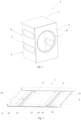
Fig. 1 housing of a household appliance, front view -
Fig. 2 washer cover panel with two beam supports, view from below - A front-
load household appliance 1 has ahousing 2 comprising afront wall 3, arear wall 4,lateral walls cover panel 7. Thecover panel 7 is arranged on the upper portion of thehousing 2 and closes the latter from the upper side. Thecover panel 7 is formed as a panel with at least two downward oriented edge walls formed as vertical flaps, i. e. two lateral edge walls formed as vertical flaps and optionally a rear edge wall and/or a front edge wall formed as vertical flap, depending on the housing of a household appliance. In the embodiment, thecover panel 7 is formed as a panel with downward oriented three edge walls formed as vertical flaps: two lateralvertical flaps vertical flap 10. Two opposite lateralvertical flaps horizontal flap cover panel 7. Thecover panel 7 is fastened to thehousing 2 of ahousehold appliance 1 by way of a plug/recess clip-on system (not subject of the invention) arranged on thehorizontal flaps housing 2, preferably thelateral walls cover panel 7 becoming disengaged from the clip-on system due to vibration, thecover panel 7 is additionally screw-fastened to therear edge wall 10 to therear wall 4 of the housing. - The
cover panel 7 comprises at least onesupport 14 arranged at a clearance from anunderside 15 of the cover panel, extending between the two lateralvertical flaps free end horizontal flap support 14 is configured as a support of a conventional shape, such as a quadrangular beam, T-beam, U-beam, I-beam or of any other shape. In the embodiment, the support is configured as a U-beam. Thesupport 14 is made of a metallic material, such as ferrous alloys or light metals, or a non-metallic material, such as a plastic material, meeting requirements regarding material stiffness, so that it can resist loads without getting plastically deformed. - Each
horizontal flap more stops 18. Thestop 18 may be configured as a protrusion or a recess co-operating with a complementary shaped respective free end of thesupport 14 to prevent sliding of thesupport 14, more precisely itsfree end horizontal flap stops 18 on eachhorizontal flap stop 18 configured as a positive protrusion projects from thehorizontal flap support 14, i.e. away from the ground. Thestop 18 configured as a negative protrusion projects from thehorizontal flap support 14, i.e. towards the ground. Thestop 18 configured as a protrusion or recess may be produced during the process of shaping thehorizontal flap cover panel 7 and thehorizontal flap stop 18 may also be made by other technological processes, e.g. by a cutting, punching or bending process. - The
support 14 acts on theunderside 15 of the cover panel through aninsulation material layer 19 which is arranged at least in part between atop face 11 of thesupport 14 and theopposite underside 15 of the cover panel. In the embodiment, this is achieved in a way that the thickness of eachinsulation material layer 19, before being built-in, is larger than the clearance between thetop face 11 of each support and the opposingunderside 15 of the cover panel in the assembled state. Thus, in the assembled state, theinsulation material layer 19 gets compressed in the area between the two faces 11, 15 or elastically and partially plastically deformed, i.e. theinsulation material layer 19 exerts an identical vertical force on each of said faces 11, 15. As a result, it acts as a limiter of the vertical movement of thesupport 14 and fixes it in the vertical direction. At the same time, thesupport 14 fixes theinsulation material layer 19 to theunderside 15 of the cover panel. Theinsulation material layer 19 also dampens vibrations transferred from thesupport 14 to thecover 7. The ratio between the thickness of theinsulation material layer 19 and said clearance can be roughly defined by the elastic modulus value of the insulation material. At lower elastic modulus values, the ratio should be higher. The values of said ratio, the shape of the support and the shape of the insulation panels can be defined using known engineering approaches, such as use of modern computer tools, experimental work, etc., depending on specific requirements, such as household appliance type, vibration generation, etc. - The
insulation material layer 19 is arranged at least in the area of arespective support 14. Theinsulation material layer 19 may be arranged over theentire underside 15 of the cover panel, which reduces the noise due to vibrations of the household appliance during operation. - The
housing 2 is preferably made of sheet metal. Thecover panel 7 closing thehousing 2 is made of a metallic material, such as steel sheet metal or light sheet metal, or a non-metallic material, such as a plastic material, meeting requirements regarding material stiffness, so that it can resist loads without getting plastically deformed.
Claims (11)
- A front-load household appliance (1), more particularly a washer, dryer or washer-dryer, has a housing (2) that comprises a front wall (3), a rear wall (4), lateral walls (5, 6) and a cover panel (7) with an underside (15), the cover panel (7) being configured as a panel with at least two downward oriented edge lateral walls (8, 9) formed as vertical flaps, and optionally with a rear edge wall (10) formed as a vertical flap and/or a front edge wall formed as a vertical flap, the two opposite edge walls formed as vertical flaps, preferably lateral edge walls formed as vertical flaps (8, 9), each having a horizontal flap (12, 13) projecting into the interior of the cover panel (7),
characterized in that the cover panel (7) comprisesat least one support (14) arranged at a clearance from an underside (15) of the cover panel, extending between the two vertical flaps (8, 9) and abutting with a respective free end (16, 17) on the complementary horizontal flap (12, 13), each horizontal flap (12, 13) comprising at least one stop (18) co-operating with a complementary shaped respective free end (16, 17) of the support (14) to prevent sliding of the support (14), more precisely its free end (16, 17), along the horizontal flap (12, 13),an insulation material layer (19) arranged at a clearance between the support (14) and the underside (15) of the cover panel. - The household appliance according to claim 1, characterized in that the stop (18) is configured as a protrusion or/and a recess.
- The household appliance according to any preceding claim, characterized in that the stop (18) in the form of a protrusion is configured as a positive protrusion projecting from the horizontal flap (12, 13) in a direction away from the floor, or as a negative protrusion projecting from the horizontal flap (12, 13) towards the floor.
- The household appliance according to any preceding claim, characterized in that the number of stops (18) on each horizontal flap (12, 13) is at least equal to the number of supports beams (14), but may also be higher.
- The household appliance according to any preceding claim, characterized in that the thickness of the insulation material layer (19), before being built-in, is larger than the clearance between a top face (11) of each built-in support (14) and the opposing underside (15) of the cover panel (7).
- The household appliance according to any preceding claim, characterized in that the thickness of the insulation material layer (19) is such that in the built-in state it acts with an identical vertical force on the top face (11) of each built-in support (14) and the opposing underside (15) of the cover panel (7).
- The household appliance according to any preceding claim, characterized in that the insulation material layer (19) is arranged at least in the area of a respective support (14).
- The household appliance according to any preceding claim, characterized in that the insulation material layer (19) is arranged over the entire underside (15) of the cover panel (7).
- The household appliance according to any preceding claim, characterized in that the support (14) is configured as a support of a conventional shape, in a shape of a quadrangular beam, T-beam, U-beam, I-beam or of any other shape.
- The household appliance according to any preceding claim, characterized in that the support (14) is made of a metallic material, such as ferrous alloys or light metals, or a non-metallic material, such as a plastic material, meeting requirements regarding material stiffness, so that it can resist loads without getting plastically deformed.
- The household appliance according to any preceding claim, characterized in that the cover panel (7) is made of a metallic material or a plastic material.
Applications Claiming Priority (1)
| Application Number | Priority Date | Filing Date | Title |
|---|---|---|---|
| SI202300078A SI26524A (en) | 2023-05-30 | 2023-05-30 | Household appliance with lid |
Publications (2)
| Publication Number | Publication Date |
|---|---|
| EP4471203A1 true EP4471203A1 (en) | 2024-12-04 |
| EP4471203B1 EP4471203B1 (en) | 2026-04-29 |
Family
ID=91331171
Family Applications (1)
| Application Number | Title | Priority Date | Filing Date |
|---|---|---|---|
| EP24178822.3A Active EP4471203B1 (en) | 2023-05-30 | 2024-05-29 | Household appliance with a cover panel |
Country Status (2)
| Country | Link |
|---|---|
| EP (1) | EP4471203B1 (en) |
| SI (1) | SI26524A (en) |
Citations (3)
| Publication number | Priority date | Publication date | Assignee | Title |
|---|---|---|---|---|
| EP2778276A1 (en) * | 2013-03-13 | 2014-09-17 | Miele & Cie. KG | Housing for household appliances and method for preparing a housing for household appliances |
| CN110093754A (en) * | 2019-04-19 | 2019-08-06 | 无锡小天鹅电器有限公司 | Top cover, casing assembly and the washing machine of washing machine |
| EP3798351A1 (en) * | 2019-09-30 | 2021-03-31 | Whirlpool Corporation | Appliance lid that incorporates interior structural foam reinforcement |
-
2023
- 2023-05-30 SI SI202300078A patent/SI26524A/en active IP Right Grant
-
2024
- 2024-05-29 EP EP24178822.3A patent/EP4471203B1/en active Active
Patent Citations (3)
| Publication number | Priority date | Publication date | Assignee | Title |
|---|---|---|---|---|
| EP2778276A1 (en) * | 2013-03-13 | 2014-09-17 | Miele & Cie. KG | Housing for household appliances and method for preparing a housing for household appliances |
| CN110093754A (en) * | 2019-04-19 | 2019-08-06 | 无锡小天鹅电器有限公司 | Top cover, casing assembly and the washing machine of washing machine |
| EP3798351A1 (en) * | 2019-09-30 | 2021-03-31 | Whirlpool Corporation | Appliance lid that incorporates interior structural foam reinforcement |
Also Published As
| Publication number | Publication date |
|---|---|
| EP4471203B1 (en) | 2026-04-29 |
| SI26524A (en) | 2024-12-31 |
Similar Documents
| Publication | Publication Date | Title |
|---|---|---|
| EP1928705B1 (en) | A crash box and a method of fastening a bumper beam | |
| US7014283B2 (en) | Localized reinforcement system for refrigerator cabinet | |
| JP4405327B2 (en) | Front fender structure | |
| US6381917B1 (en) | Lift door panel | |
| EP4471203A1 (en) | Household appliance with a cover pane | |
| EP2062500B1 (en) | Top board structure | |
| JP2017077389A (en) | Connecting reinforcement | |
| KR200449811Y1 (en) | Fixing bracket | |
| EP4549186A1 (en) | Panel set | |
| KR102336056B1 (en) | Fixture for Fastening Ceiling Finishing Bar | |
| US11377879B2 (en) | Motor vehicle latch | |
| CN110905342B (en) | Doors with in-frame reinforcements and doors | |
| EP3571357B1 (en) | Drift clip | |
| KR102699462B1 (en) | Construction panel structure with earthquake-resistant function | |
| KR102911751B1 (en) | A prefabricated iron desk and method of manufacturing iron desk | |
| EP4400642A1 (en) | Washing machine with improved shock absorber fixation and process for its manufacture | |
| JP3481584B2 (en) | Joist mounting hardware | |
| JP2020165245A (en) | Building construction method and low outer wall material | |
| WO2020164033A1 (en) | Bracket element attaching wheel housing to the rear parcel shelf | |
| JP3419737B2 (en) | Roof mounting bracket | |
| KR200318034Y1 (en) | a panel for partition | |
| JP5898654B2 (en) | Lumbar panel frame fixing structure | |
| CN210652612U (en) | Glass guide rail bracket with pre-hanging function and glass guide rail assembly | |
| JP2019173396A (en) | Inner wall structure | |
| JP4053675B2 (en) | Beam receiving hardware |
Legal Events
| Date | Code | Title | Description |
|---|---|---|---|
| PUAI | Public reference made under article 153(3) epc to a published international application that has entered the european phase |
Free format text: ORIGINAL CODE: 0009012 |
|
| STAA | Information on the status of an ep patent application or granted ep patent |
Free format text: STATUS: THE APPLICATION HAS BEEN PUBLISHED |
|
| AK | Designated contracting states |
Kind code of ref document: A1 Designated state(s): AL AT BE BG CH CY CZ DE DK EE ES FI FR GB GR HR HU IE IS IT LI LT LU LV MC ME MK MT NL NO PL PT RO RS SE SI SK SM TR |
|
| STAA | Information on the status of an ep patent application or granted ep patent |
Free format text: STATUS: REQUEST FOR EXAMINATION WAS MADE |
|
| 17P | Request for examination filed |
Effective date: 20250603 |
|
| GRAP | Despatch of communication of intention to grant a patent |
Free format text: ORIGINAL CODE: EPIDOSNIGR1 |
|
| STAA | Information on the status of an ep patent application or granted ep patent |
Free format text: STATUS: GRANT OF PATENT IS INTENDED |
|
| INTG | Intention to grant announced |
Effective date: 20251126 |
|
| GRAS | Grant fee paid |
Free format text: ORIGINAL CODE: EPIDOSNIGR3 |
|
| GRAA | (expected) grant |
Free format text: ORIGINAL CODE: 0009210 |
|
| STAA | Information on the status of an ep patent application or granted ep patent |
Free format text: STATUS: THE PATENT HAS BEEN GRANTED |
|
| RAP3 | Party data changed (applicant data changed or rights of an application transferred) |
Owner name: GORENJE GOSPODINJSKI APARATI, D.O.O. |
|
| AK | Designated contracting states |
Kind code of ref document: B1 Designated state(s): AL AT BE BG CH CY CZ DE DK EE ES FI FR GB GR HR HU IE IS IT LI LT LU LV MC ME MK MT NL NO PL PT RO RS SE SI SK SM TR |
|
| REG | Reference to a national code |
Ref country code: CH Ref legal event code: F10 Free format text: ST27 STATUS EVENT CODE: U-0-0-F10-F00 (AS PROVIDED BY THE NATIONAL OFFICE) Effective date: 20260429 |