Technical Field
-
The disclosure relates to a technique of a flat knitting machine including a needle bed and a bed-like member provided movably relative to the needle bed.
Background Art
-
Conventionally, a technique of a flat knitting machine including a needle bed is known. For example, Patent Literature 1 discloses such a configuration.
-
Patent Literature 1 discloses a flat knitting machine including at least two needle beds facing each other in the front-back direction across a needle bed gap, in which a large number of knitting needles are arranged on the needle bed so as to be movable forward and backward. In such a flat knitting machine, at least two needle beds facing each other in the front-back direction are configured to be relatively movable (racking). In addition, an auxiliary floor (bed-like member) such as a loop pressor or a transfer jack may be provided separately from the needle bed. It is conceivable to individually drive each bed, but an error (a difference in responsiveness or an error in a stop position) in driving of each bed may cause collision between members or hindrance to knitting of a knitted fabric.
Citation List
Patent Literature
-
Patent Literature 1:
Japanese Patent No. 3044373 Summary of Invention
Technical Problem
-
The disclosure has been made in view of the above circumstances, and an object to be solved by the disclosure is to provide a flat knitting machine capable of avoiding occurrence of collision between members and hindrance to knitting of a knitted fabric due to an error in driving of a needle bed and a bed-like member.
Solution to Problem
-
The problem to be solved by the disclosure is as described above, and means for solving the problem will be described below.
-
That is, a flat knitting machine according to the disclosure includes: at least two needle beds facing each other in a front-back direction; a first drive source that is coupled to each of the needle beds and generates a drive force for relatively moving the front and back needle beds in a longitudinal direction; a bed-like member provided to be relatively movable with respect to each of the needle beds; a second drive source that is coupled to the bed-like member and generates a drive force for moving the bed-like member; and a control unit that is capable of controlling operations of the first drive source and the second drive source, in which the second drive source is coupled to each of the needle beds, and in which the control unit is capable of moving each of the needle beds by driving the first drive source, is capable of moving the bed-like member integrally with each of the needle beds along with movement of the second drive source along with movement of each of the needle beds, and is capable of moving the bed-like member relative to each of the needle beds by driving the second drive source.
-
With this configuration, it is possible to avoid collision between members due to an error in driving of the needle bed and the bed-like member.
-
Further, a relatively movable range of the bed-like member with respect to each of the needle beds may be smaller than a relatively movable range of each of the needle beds.
-
With such a configuration, when relatively moving the bed-like member with respect to the needle bed, the bed-like member can be avoided from colliding with other members and causing hindrance to knitting of a knitted fabric.
-
Further, the flat knitting machine may further include a coupling member that is formed so as to extend along each of the needle beds and couples each of the needle beds and the first drive source, and the second drive source may be coupled to the coupling member.
-
With such a configuration, the second drive source can be coupled to the needle bed via the coupling member, whereby the degree of freedom of the disposing position of the second drive source can be improved.
-
Further, the second drive source may be disposed above each of the needle beds and on a side of the bed-like member.
-
With such a configuration, maintainability of the second drive source can be improved.
Advantageous Effects of Invention
-
As an effect of the disclosure, it is possible to avoid occurrence of collision between members and hindrance to knitting of a knitted fabric due to an error in driving of the needle bed and the bed-like member.
Brief Description of Drawings
-
- FIG. 1 is a schematic side view showing a configuration of a flat knitting machine according to a first embodiment;
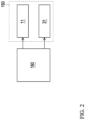
- FIG. 2 is a block diagram showing a control unit and a drive mechanism of the flat knitting machine;
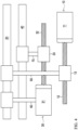
- FIG. 3 is a schematic front view showing a disposing position of a drive mechanism of the first embodiment;
- FIG. 4 is a schematic view showing a relationship of coupling of members of the drive mechanism of the first embodiment; and
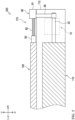
- FIG. 5 is a schematic front view showing a disposing position of a drive mechanism of a second embodiment. Description of Embodiments
-
In the following description, directions indicated by arrows U, D, F, B, L, and R in the drawings are defined as an upward direction, a downward direction, a forward direction, a backward direction, a left direction, and a right direction, respectively.
-
As illustrated in FIGS. 1 and 2, a flat knitting machine 100 according to an embodiment of the disclosure mainly includes needle beds 110, carriages 120, yarn path rails 130, loop pressor beds 140, drive mechanisms 150, and a control unit 160.
-
The needle beds 110 are disposed so as to face each other in the front-back direction across a needle bed gap S. The front and back needle beds 110 are disposed in an inverted V shape in a side view so as to be inclined upward toward the front and back center sides (sides facing each other). Each needle bed 110 is provided with a large number of knitting needles 111 arranged along the longitudinal direction (left-right direction) of the needle bed 110. The front and back needle beds 110 can be relatively moved in the longitudinal direction of the needle bed 110 when transferring the stitches to each other.
-
A pair of front and back carriages 120 are disposed to face the front and back needle beds 110 from above. The front and back carriages 120 are coupled by a bridge 120a disposed to straddle the plurality of yarn path rails 130. The carriage 120 can reciprocate along the longitudinal direction of the needle bed 110 by a servo motor (not illustrated). The carriage 120 is provided with a needle selecting mechanism (not illustrated) and a cam mechanism (not illustrated) for selectively operating the knitting needles 111 of the needle bed 110.
-
The plurality of yarn path rails 130 are disposed above the needle bed gap S so as to extend along the longitudinal direction of the needle bed 110. A yarn carrier (not illustrated) that feeds a knitting yarn is supported on the yarn path rail 130 so as to be movable.
-
Above the needle bed 110, a loop pressor bed 140 in which a large number of loop pressors 141 are supported so as to be movable forward and backward with respect to the needle bed gap S is provided. The loop pressor bed 140 is an example of a "bed-like member" of the disclosure. The loop pressor 141 is configured to advance toward the needle bed gap S to press a yarn and an inlay yarn extending between the stitches, and to prevent the knitted fabric and the yarn from floating up.
-
The loop pressor bed 140 is provided such that the longitudinal direction of the loop pressor bed 140 faces the longitudinal direction of the needle bed 110. The loop pressor bed 140 is provided to be relatively movable in the longitudinal direction of the needle bed 110 with respect to the needle bed 110. The needle bed 110 and the loop pressor bed 140 are moved by the drive mechanism 150. The configuration of the drive mechanism 150 will be described later.
-
The control unit 160 controls the operation of the flat knitting machine 100. The control unit 160 includes a storage unit such as a RAM, a ROM, and an HDD, an arithmetic processing unit such as a CPU, and the like. The control unit 160 can reciprocate the carriage 120 along the longitudinal direction of the needle bed 110 by controlling the operation of the servo motor. When reciprocating, the carriage 120 entrains the yarn carrier to be fed. In this case, the knitting operation such as knitting, tuck, missing, and the like, and the transfer of the stitches between the front and back needle beds 110 can be carried out by advancing and retreating the knitting needles 111 with respect to the needle bed gap S by cam mechanisms (not illustrated) mounted on the carriages 120, and the like. The knitted fabric is knitted by repeating such reciprocating movement of the carriages 120.
-
As shown in FIG. 2, the control unit 160 is electrically connected to a first drive motor 11 and a second drive motor 31 to be described later of the drive mechanism 150, and can appropriately control the operations of the first drive motor 11 and the second drive motor 31 based on the knitting program. The needle bed 110 and the loop pressor bed 140 can be moved by operating the first drive motor 11 and the second drive motor 31.
-
Here, the loop pressor 141 is provided at a position overlapping a movable sinker (not illustrated) provided on the needle bed 110 in a side view, and is provided between the movable sinkers in a plan view. A movable range of the loop pressor bed 140 relative to the needle bed 110 is set within 1 pitch. Here, 1 pitch is the length in the longitudinal direction of the needle bed 110 of the interval between the adjacent knitting needles 111.
-
As described above, the movable range of the loop pressor bed 140 relative to the needle bed 110 is set to a very short distance so that the loop pressor 141 and the movable sinker do not collide with each other. However, if the movement of the needle bed 110 and the loop pressor bed 140 is individually controlled, a difference in responsiveness between the drive source of the needle bed 110 and the drive source of the loop pressor bed 140 and an error in the stop position of each of the needle bed 110 and the loop pressor bed 140 are integrated, so that the loop pressor 141 may collide with the movable sinker. Therefore, in the flat knitting machine 100 according to the present embodiment, the loop pressor bed 140 is configured to be integrally movable with the needle bed 110 by the drive mechanism 150.
-
Next, a configuration of the drive mechanism 150 will be described with reference to FIGS. 3 and 4. In FIG. 3 and FIG. 5 to be described later, hatching is applied to the needle bed 110 and the loop pressor bed 140 in order to clarify each member.
-
The drive mechanism 150 moves the needle bed 110 and the loop pressor bed 140 in the longitudinal direction. In the present embodiment, one drive mechanism 150 is provided for the needle bed 110 and the loop pressor bed 140 on the front side, and one drive mechanism 150 is provided for the needle bed 110 and the loop pressor bed 140 on the back side. The drive mechanism 150 mainly includes a first drive source 10, a first sliding plate 20, a second drive source 30, and a second sliding plate 40.
-
The first drive source 10 generates a drive force for relatively moving the needle bed 110 in the longitudinal direction. The first drive source 10 is disposed inside the body bed 112 (see FIG. 3) of the needle bed 110. The first drive source 10 includes a first drive motor 11 and a ball screw 12. When the first drive motor 11 is driven, the ball screw 12 rotates, and a nut 13 screwed into the ball screw 12 linearly moves in the longitudinal direction of the needle bed 110.
-
The first sliding plate 20 is a longitudinal platelike member, and is provided so as to extend along the body bed 112 of the needle bed 110 with the longitudinal direction of the first sliding plate 20 oriented in the longitudinal direction of the needle bed 110. One end of the first sliding plate 20 is coupled to one end (right end in FIG. 3) of the needle bed 110. The nut 13 screwed into the ball screw 12 of the first drive source 10 is coupled to a middle portion of the first sliding plate 20 in the longitudinal direction via an intermediate member 50.
-
In this way, the first sliding plate 20 couples the needle bed 110 and the ball screw 12 of the first drive source 10. Thus, when the first drive motor 11 is driven, the needle bed 110 can be moved in the longitudinal direction. The first sliding plate 20 is an example of a "coupling member" of the disclosure.
-
The second drive source 30 generates a drive force for moving the loop pressor bed 140. The second drive source 30 is disposed inside the body bed 112 of the needle bed 110. The second drive source 30 includes a second drive motor 31 and a ball screw 32. When the second drive motor 31 is driven, the ball screw 32 rotates, and the nut 33 screwed into the ball screw 32 linearly moves in the longitudinal direction of the needle bed 110. The second drive source 30 is housed in a housing (not illustrated), and the housing is coupled to the first sliding plate 20 via the intermediate member 60. The second drive source 30 is coupled to the first sliding plate 20 at a middle portion of the first sliding plate 20 in the longitudinal direction.
-
In this way, the second drive source 30 is coupled to the needle bed 110 via the first sliding plate 20 and the like.
-
The second sliding plate 40 is a longitudinal platelike member, and is provided so as to extend along the body bed 112 of the needle bed 110 with the longitudinal direction of the second sliding plate 40 oriented in the longitudinal direction of the needle bed 110. The second sliding plate 40 is provided above the first sliding plate 20. One end of the second sliding plate 40 is coupled to one end (right end in FIG. 3) of the loop pressor bed 140 via an appropriate member. The nut 33 screwed into the ball screw 32 of the second drive source 30 is coupled to a middle portion of the second sliding plate 40 in the longitudinal direction via an intermediate member 70.
-
In this way, the second sliding plate 40 couples the loop pressor bed 140 and the ball screw 32 of the second drive source 30. Thus, when the second drive motor 31 is driven, the loop pressor bed 140 can be moved in the longitudinal direction.
-
Next, a mode of movement of the needle bed 110 and the loop pressor bed 140 will be described.
-
When the control unit 160 drives the first drive motor 11 of the first drive source 10, the rotational motion of the ball screw 12 is converted into linear motion, and the first sliding plate 20 coupled to the ball screw 12 moves in the left-right direction. Along with the movement of the first sliding plate 20, the needle bed 110 moves in the left-right direction, and the housing coupled to the first sliding plate 20 and the second drive source 30 accommodated in the housing move in the left-right direction. As the second drive source 30 moves, the second sliding plate 40 coupled to the second drive source 30 moves in the left-right direction, and as the second sliding plate 40 moves, the loop pressor bed 140 moves in the left-right direction.
-
In this way, by coupling the second drive source 30 and the needle bed 110, when the first drive source 10 is driven, the needle bed 110 and the loop pressor bed 140 can be integrally moved. The second drive source 30 is not directly coupled to the needle bed 110 but is coupled via the first sliding plate 20 or the like. Therefore, the degree of freedom of the disposing position of the second drive source 30 can be improved, and for example, the second drive source 30 can be included in the space under the needle bed 110 as in the present embodiment, so that the mechanism can be made compact.
-
On the other hand, when the control unit 160 drives the second drive motor 31 of the second drive source 30, the rotational motion of the ball screw 32 is converted into linear motion, and the second sliding plate 40 coupled to the ball screw 32 moves in the left-right direction. As the second sliding plate 40 moves, the loop pressor bed 140 moves in the left-right direction.
-
Thus, when the second drive source 30 is driven, the loop pressor bed 140 can be moved relative to the needle bed 110.
-
The control unit 160 can selectively drive the first drive source 10 and the second drive source 30 based on the knitting program.
-
By driving the first drive source 10, the control unit 160 can move the loop pressor bed 140 integrally with the needle bed 110 without driving the second drive source 30. By integrally moving the loop pressor bed 140 and the needle bed 110, the influence of the difference in responsiveness and the error in the stop position can be reduced. Therefore, it is possible to avoid the loop pressor 141 from colliding with other members such as the movable sinker.
-
On the other hand, the control unit 160 can adjust the relative position of the loop pressor bed 140 with respect to the needle bed 110 by driving the second drive source 30. As a result, it is possible to avoid the loop pressor 141 that has advanced to the needle bed gap S side from interfering with a member such as the movable sinker provided on the needle bed 110 on the opposing side.
-
Specifically, depending on the positional relationship between the front and back needle beds 110 and the positional relationship of the loop pressor bed 140 with respect to the needle bed 110, there is a case where the front and back loop pressors 141 are at positions facing each other and only the loop pressor 141 on one side can advance, or there is a case where the loop pressor 141 is at a position facing the movable sinker on the opposing side and when the loop pressor 141 is advanced to the needle bed gap S side, the loop pressor 141 interferes with the movable sinker on the opposing side. In such a case, by adjusting the relative position of the loop pressor bed 140 with respect to the needle bed 110, the loop pressor 141 can be advanced to the needle bed gap S side without interfering with other members.
-
Next, a configuration of a flat knitting machine 200 according to a second embodiment of the disclosure will be described with reference to FIG. 5. Hereinafter, the same components as those of the first embodiment are denoted by the same reference numerals, and description thereof is omitted.
-
The flat knitting machine 200 according to the second embodiment includes a drive mechanism 170 in place of the drive mechanism 150, and the drive mechanism 170 includes a second drive source 80 in place of the second drive source 30. In the first embodiment, the second drive source 30 is coupled to the loop pressor bed 140 via the second sliding plate 40, whereas in the second embodiment, the second drive source 80 is directly coupled to the loop pressor bed 140. The second drive source 80 is disposed above the needle bed 110 and on the side (right side) of the loop pressor bed 140. The second drive source 80 is disposed such that the second drive motor 81, the ball screw 82, and the loop pressor bed 140 are linear. A nut 83 screwed into the ball screw 82 of the second drive source 80 is coupled to one end of the loop pressor bed 140. The second drive motor 81 of the second drive source 80 is coupled to the first sliding plate 20 via an intermediate member 90 such as a base member that supports the second drive motor 81.
-
Similarly to the flat knitting machine 100 according to the first embodiment, also in the flat knitting machine 200 according to the second embodiment, the control unit 160 drives the first drive source 10 to move the loop pressor bed 140 integrally with the needle bed 110. On the other hand, the control unit 160 can relatively move the loop pressor bed 140 with respect to the needle bed 110 by driving the second drive source 80.
-
In the second embodiment, since the second drive source 80 is disposed above the needle bed 110 and on the side of the loop pressor bed 140, maintainability of the second drive source 80 can be improved.
-
Although each embodiment of the disclosure has been described above, the disclosure is not limited to the above embodiment, and appropriate modifications can be made within the scope of the technical idea of the invention described in the claims.
-
For example, in the first embodiment, the first drive source 10 and the needle bed 110 are coupled via the first sliding plate 20 and the like, and the second drive source 30 and the loop pressor bed 140 are coupled via the second sliding plate 40 and the like, but the members may be directly coupled.
-
In each embodiment, the bed-like member of the disclosure is the loop pressor bed 140, but the disclosure is not limited thereto. For example, the bed-like member may be a transfer jack bed provided with a transfer jack for transfer between the front and back needle beds 110.
-
The bed-like member of the disclosure may be a sinker bed provided with a sinker (fixed sinker or movable sinker) for pressing the sinker loop at the time of creating the stitch. Specifically, the sinker is usually provided in the needle bed 110, but the sinker may be provided in a sinker bed different from the needle bed 110, and the sinker bed may be provided so as to be relatively movable with respect to the needle bed 110. In this case, the knitting needle 111 provided on the needle bed 110 is provided at a position overlapping the sinker provided on the sinker bed in a side view, and is provided between the sinkers in the plan view. Hereinafter, effects when the bed-like member is a sinker bed will be described.
-
In a case where the knitting needle 111 is a latch needle, the knitting needle 111 on the opposing side is inserted between the transfer clip (thin plates) provided on one side of the needle main body and the needle main body to perform transfer, but the knitting needle 111 is disposed in a state of being slightly shifted from the center between the sinkers by the transfer clip. Therefore, the formed stitches are not symmetrical.
-
Therefore, by providing the sinker bed above or below the needle bed 110 and making the sinker bed relatively movable with respect to the needle bed 110, the sinker bed can be relatively moved such that the knitting needle 111 is located at the center between the sinkers. Thus, the left and right uniform stitches can be formed.
-
The bed-like member of the disclosure may be the needle bed 110 on the opposing side. Furthermore, in a case where the flat knitting machine 100, 200 is a four-bed machine including two stages of front and back needle beds 110, the bed-like member of the disclosure may be the upper needle bed 110, may be a loop pressor bed provided relatively movably on the upper needle bed 110, or may be both the upper needle bed 110 and the loop pressor bed.
-
In each embodiment, the range in which the loop pressor bed 140 is relatively movable with respect to the needle bed 110 is set to be within 1 pitch, but any value can be set according to the type of the bed-like member of the disclosure. For example, the range in which the bed-like member is relatively movable with respect to the needle bed 110 may be set to be smaller than the range in which the needle bed 110 is relatively movable.
-
For example, in a case where the bed-like member of the disclosure is a transfer jack bed, the transfer jack provided in the transfer jack bed does not overlap the knitting needle 111 provided in the needle bed 110 in a side view, and thus does not cross the needle bed 110 even if the transfer jack bed is relatively moved in the longitudinal direction. Here, since the mechanism for moving the needle bed 110 and the mechanism for moving the transfer jack bed are in a master-slave relationship, the movement width of the transfer jack bed is realized by being added to the movement width of the needle bed 110. Therefore, even if the relatively movable range of the transfer jack bed is set to be smaller than the relatively movable range of the needle bed 110, the movement width of the transfer jack bed can be secured. The same applies to the case where the bed-like member of the disclosure is the needle bed 110 on the opposing side and the case where the bed-like member of the disclosure is the upper needle bed 110 in a case where the flat knitting machine 100, 200 is a four-bed machine.
Reference Signs List
-
- 10
- first drive source
- 20
- first sliding plate
- 30, 80
- second drive source
- 100, 200
- flat knitting machine
- 110
- needle bed
- 140
- loop pressor bed
- 150, 170
- drive mechanism
- 160
- control unit