EP4471197A1 - Fiber waste collection device and false-twisting machine - Google Patents
Fiber waste collection device and false-twisting machine Download PDFInfo
- Publication number
- EP4471197A1 EP4471197A1 EP24177248.2A EP24177248A EP4471197A1 EP 4471197 A1 EP4471197 A1 EP 4471197A1 EP 24177248 A EP24177248 A EP 24177248A EP 4471197 A1 EP4471197 A1 EP 4471197A1
- Authority
- EP
- European Patent Office
- Prior art keywords
- fiber waste
- air
- discharge unit
- fiber
- cyclone separator
- Prior art date
- Legal status (The legal status is an assumption and is not a legal conclusion. Google has not performed a legal analysis and makes no representation as to the accuracy of the status listed.)
- Pending
Links
Images







Classifications
-
- D—TEXTILES; PAPER
- D01—NATURAL OR MAN-MADE THREADS OR FIBRES; SPINNING
- D01H—SPINNING OR TWISTING
- D01H11/00—Arrangements for confining or removing dust, fly or the like
- D01H11/005—Arrangements for confining or removing dust, fly or the like with blowing and/or suction devices
-
- B—PERFORMING OPERATIONS; TRANSPORTING
- B04—CENTRIFUGAL APPARATUS OR MACHINES FOR CARRYING-OUT PHYSICAL OR CHEMICAL PROCESSES
- B04C—APPARATUS USING FREE VORTEX FLOW, e.g. CYCLONES
- B04C5/00—Apparatus in which the axial direction of the vortex is reversed
- B04C5/12—Construction of the overflow ducting, e.g. diffusing or spiral exits
- B04C5/13—Construction of the overflow ducting, e.g. diffusing or spiral exits formed as a vortex finder and extending into the vortex chamber; Discharge from vortex finder otherwise than at the top of the cyclone; Devices for controlling the overflow
-
- B—PERFORMING OPERATIONS; TRANSPORTING
- B65—CONVEYING; PACKING; STORING; HANDLING THIN OR FILAMENTARY MATERIAL
- B65H—HANDLING THIN OR FILAMENTARY MATERIAL, e.g. SHEETS, WEBS, CABLES
- B65H54/00—Winding, coiling, or depositing filamentary material
- B65H54/70—Other constructional features of yarn-winding machines
- B65H54/702—Arrangements for confining or removing dust
-
- D—TEXTILES; PAPER
- D02—YARNS; MECHANICAL FINISHING OF YARNS OR ROPES; WARPING OR BEAMING
- D02G—CRIMPING OR CURLING FIBRES, FILAMENTS, THREADS, OR YARNS; YARNS OR THREADS
- D02G1/00—Producing crimped or curled fibres, filaments, yarns, or threads, giving them latent characteristics
- D02G1/02—Producing crimped or curled fibres, filaments, yarns, or threads, giving them latent characteristics by twisting, fixing the twist and backtwisting, i.e. by imparting false twist
- D02G1/0206—Producing crimped or curled fibres, filaments, yarns, or threads, giving them latent characteristics by twisting, fixing the twist and backtwisting, i.e. by imparting false twist by false-twisting
- D02G1/0266—Producing crimped or curled fibres, filaments, yarns, or threads, giving them latent characteristics by twisting, fixing the twist and backtwisting, i.e. by imparting false twist by false-twisting false-twisting machines
-
- B—PERFORMING OPERATIONS; TRANSPORTING
- B65—CONVEYING; PACKING; STORING; HANDLING THIN OR FILAMENTARY MATERIAL
- B65H—HANDLING THIN OR FILAMENTARY MATERIAL, e.g. SHEETS, WEBS, CABLES
- B65H2701/00—Handled material; Storage means
- B65H2701/30—Handled filamentary material
- B65H2701/31—Textiles threads or artificial strands of filaments
Definitions
- the present invention relates to a fiber waste collection device that collects fiber wastes separated from air and a false-twisting machine including such a fiber waste collection device.
- Patent Document 1 discloses a suction device for continuously running multi-threads including a suctioning pipe arranged with a plurality of suction ports, a fiber waste collection container connected to an end of the suctioning pipe, and a negative pressure pump or suction blower connected to the fiber waste collection container.
- the pressure within the suctioning pipe becomes negative due to the operation of the negative pressure pump or suction blower, and the fiber waste suctioned into the suctioning pipe from the plurality of suction ports is suctioned through the suctioning pipe to be collected into the fiber waste collection container.
- Patent Document 1 Japanese Unexamined Patent Application Publication No. H06-40661
- the fiber waste is suctioned through the suctioning pipe to be collected by the action of the negative pressure pump or the suction blower that are connected to a downstream end side in a suction direction of the suctioning pipe via the fiber waste collection container.
- the suction device there is a risk that lint would be discharged to an exterior of the suction device together with air.
- the present invention has been made in view of the above-described technical problems, and an objective thereof is to provide a fiber waste collection device configured to separate fiber waste from air appropriately thereby capable of suppressing the discharge of lint to an exterior thereof, and a false-twisting machine including the fiber waste collection device.
- a first aspect of the present invention is a fiber waste collection device comprising:
- the fiber waste transferred through the fiber waste transfer pipe is collected into the fiber waste collection unit via the cyclone separator connected to the fiber waste transfer pipe.
- the cyclone separator separates the fiber (i.e ., fiber waste) from the air transferred through the fiber waste transfer pipe.
- the fiber waste separated from air is collected into the fiber waste collection unit, and the air separated from the fiber waste is discharged to an exterior through the air discharge unit, thereby appropriately separating fiber waste and air.
- some fiber wastes that were not carried by the flow travelling downward along the inner peripheral wall of the body portion may head for the air discharge unit and may be discharged through the air discharge unit to an exterior.
- the lint may become entangled with workers, which is undesirable from a safety and sanitary standpoint.
- the shielding member has a gap larger than a diameter of the lint, and is configured such that the flow rate of air in the air discharge unit is larger than the flow rate of air in the fiber waste discharge unit. Therefore, while maintaining desirable separation between the fiber waste and the air, it is possible to prevent lint from being discharged to an exterior and prevent the entanglement of lint discharged to an exterior through the air discharge unit with the workers.
- the expression "provided at a predetermined site on a path from where the air separated from the fiber waste flows into the air discharge unit to where the air is discharged to the exterior" regarding the “shielding member" in the above-described first aspect means that it is sufficient that the lint flowed into the air discharge unit is blocked and prevented from being discharged to an exterior through the air discharge unit.
- the shielding member is not limited to being provided at a specific site, for example, an opening at the boundary between the air discharge unit and the exterior ( i.e ., an opening at the end portion of the air discharge unit).
- blocking lint from being discharged to the exterior through the air discharge unit in the above-described first aspect means, for example, catching lint before it is discharged to the exterior.
- the “exterior” corresponds to a region outside the components constituting the cyclone separator, such as a region in the atmosphere.
- a second aspect of the present invention is the fiber waste collection device according to the above-described first aspect, which is
- the fiber waste collection device it is possible to transfer the fiber waste by a centrifugal force along the inner peripheral wall of the tubular body portion to the fiber waste transfer portion that is positioned below, and form the fiber waste into a ball and collect it in the fiber waste collection unit, thereby preventing fiber waste from being discharged to an exterior through the air discharge unit.
- a third aspect of the present invention is the fiber waste collection device, wherein the fiber waste transfer pipe preferably includes a plurality of fiber waste transfer pipes, and the cyclone separator preferably includes a plurality of cyclone separators each arranged for each of the plurality of fiber waste transfer pipes.
- the above-described third aspect of the fiber waste collection device includes a plurality of cyclone separators each arranged for each of the plurality of fiber waste transfer pipes. More specifically, the plurality of fiber waste transfer pipes and the plurality of cyclone separators can be connected on a one-to-one basis, thus connecting the fiber waste transfer pipes and the cyclone separators without having any restrictions imposed by another fiber waste transfer pipe. As a result, the fiber waste transfer pipes and the cyclone separators can be connected at appropriate positions where the fiber waste and air are desirably separated. Note that, the expression "appropriate position" corresponds to, for example, a position where the fiber waste transfer pipes are below the lower end portion of the air discharge unit.
- the cyclone separator includes a tubular body portion as in the above-described second aspect of the fiber waste collection device
- the inner peripheral wall of the tubular body portion can be ensured and the fiber waste can be securely sent to the lower part of the body portion (or to the fiber waste transfer portion if the fiber waste transfer portion is provided below the body portion).
- the fiber waste transfer portion is provided below the body portion.
- lint discharged from the air discharge unit of one cyclone separator may become entangled with lint discharged from the air discharge unit of another cyclone separator.
- the fiber waste collection device provided, in general, with the above-described first aspect of the shielding members, it is possible to suppress entanglement of lint discharged from the air discharge unit of one cyclone separator with lint discharged from the air discharge unit of another cyclone separator.
- a fourth aspect pf the present invention is the fiber waste collection device, wherein the fiber waste transfer pipe preferably includes a plurality of fiber waste transfer pipes, and the fiber waste collection unit is preferably provided in a number smaller than a number of the plurality of fiber waste transfer pipes.
- the number of the fiber waste collection units is smaller than the number of the fiber waste transfer pipes, thus allowing a reduction in the overall size of the fiber waste collection device.
- the fiber waste can be made into a ball to be discharged, thereby reducing the volume occupied with the fiber waste within the fiber waste collection unit.
- the volume occupied with the air can be reduced in comparison to a method incapable of isolating air used in a conventional fiber waste collection device, for example, having a blower connected to a fiber waste transfer pipe, or the like.
- the fiber waste collection device of the present invention As a result, according to the fiber waste collection device of the present invention, a larger amount of fiber waste can be accumulated in the fiber waste collection unit in comparison to a conventional fiber waste collection device, thereby reducing the number of the fiber waste collection units. Further, with such a small number of fiber waste collection units, for example, a frequency of replacement can be reduced, thereby reducing burden on a worker.
- a fifth aspect of the present invention is the fiber waste collection device, wherein the air discharge unit is preferably arranged such that the air discharge unit does not reside within an interior of the body portion and an interior of the air discharge unit communicates with the interior of the body portion.
- the air discharge unit is provided such that it does not reside within an interior of the body portion while communicating with the interior of the body portion, the fiber waste and air can be desirably separated without the fiber waste becoming tangled with the air discharge unit.
- a sixth aspect of the present invention is the fiber waste collection device, wherein the fiber waste transfer portion preferably has an inclined portion with a diameter decreasing from the body portion toward the fiber waste discharge unit.
- the fiber waste and air can be separated in the inclined portion, the discharge of the fiber waste from the air discharge unit to an exterior thereof can further be suppressed.
- a seventh aspect of the present invention is the fiber waste collection device, the fiber waste preferably includes a polyester fiber or a polyamide fiber, and the inclined portion is preferably formed in a tapered shape having an angle formed with respect to a vertical direction within a range of larger than or equal to 7° and smaller than or equal to 10°.
- fiber waste and air can be separated more accurately, and the fiber waste discharge unit can be made large enough to discharge the fiber waste, thereby preventing the fiber waste from clogging.
- An eighth aspect of the present invention is the fiber waste collection device, the air discharge unit is preferably configured such that an open area at a portion communicating with an interior of the body portion in a horizontal direction is larger than an open area of the fiber waste discharge unit in the horizontal direction.
- the open area of the air discharge unit at a portion communicating with the interior of the body portion in the horizontal direction is made larger than the open area of the fiber waste discharge unit in the horizontal direction, thereby more effectively preventing fiber waste from being discharged to an exterior through the air discharge unit.
- a ninth aspect of the present invention is a false-twisting machine preferably comprising the fiber waste collection device in any one of the above-described first to eighth aspects.
- the fiber waste collection device may be obtained by arbitrarily combining the above-described first aspect of configuration and any of the above-described second to eighth aspect of configurations to an extent such that consistency can be ensured.
- a fiber waste collection device configured to separate fiber waste from air appropriately, thereby capable of suppressing the discharge of lint to an exterior thereof, and a false-twisting machine including the fiber waste collection device.
- the present invention can be widely applied to various uses as a fiber waste collection device arranged in a textile machine such as a false-twisting machine so as to collect fiber wastes.
- FIG. 1 is a schematic view showing a false-twisting machine 101 as a textile machine arranged with a fiber waste collection device 1 (see FIG. 2).
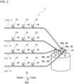
- FIG. 2 is a schematic view showing an example of the fiber waste collection device 1 according to an embodiment of the present invention.
- the fiber waste collection device 1 is arranged in a textile machine, such as the false-twisting machine 101 or a spinning machine.
- the false-twisting machine 101 will be described as an example of the textile machine in which the fiber waste collection device 1 is provided.
- the false-twisting machine 101 arranged with the fiber waste collection device 1 will be described, and subsequently, the fiber waste collection device 1 according to an embodiment of the present invention will be described.
- an up-and-down direction, a forward-and-backward direction, and a left-and-right direction in the false-twisting machine 101 and the fiber waste collection device 1 are defined as shown in FIGS. 1 and 2 .
- the false-twisting machine 101 is configured, as a textile machine, to false-twist thermoplastic synthetic fibers such as polyester and polyamide so as to impart crimps to the false-twisted fibers, thereby producing highly stretchable textured yarns.
- a main machine base 102 is arranged so as to extend in an up-and-down direction.
- the false-twisting machine 101 includes: a yarn feeding creel 104 arranged so as to face the main machine base 102 across a work space 103 and holding a plurality of yarn feeding packages 105; a false-twisting device 106 arranged above the main machine base 102 so as to false-twist a fiber Y as a yarn supplied from the yarn feeding creel 104; a winder 107 arranged on the main machine base 102 so as to wind the false-twisted fiber Y obtained in the false-twisting device 106; and the like.
- the winders 107 are arranged in four stages along the up-and-down direction.
- a plurality of winders 107 are arranged side by side along a forward-and-backward direction in each of the first to fourth stages. It is to be noted that the forward-and-backward direction in which the plurality of winders 107 are arranged in each of the four stages arranged in the up-and-down direction is a direction along a horizontal direction as well as a direction vertical to a direction (left-and-right direction) in which the yarn feeding creel 104 and the main machine base 102 are arranged.
- a first feeding roller 108, a shifter guide 109, a first heating device 110, and a cooling device 111 are arranged in this order from an upstream side in a yarn traveling direction on a yarn path from the yarn feeding creel 104 to the false-twisting device 106.
- a second feeding roller 112, an interlace nozzle 113, a second heating device 114, a third feeding roller 115, and an oiling roller 116 are arranged in this order from an upstream side in a yarn traveling direction on a yarn path from the false-twisting device 106 to the winder 107.
- the first feeding roller 108 is arranged above the work space 103.
- the first heating device 110 is arranged above the work space 103 and further above the first feeding roller 108.
- the cooling device 111 is arranged closer to the main machine base 102 than to the first heating device 110 above the work space 103.
- the first heating device 110 and the cooling device 111 are arranged above the work space 103 so as to extend obliquely upward while being separated from the main machine base 102.
- the shifter guide 109 is arranged between the first feeding roller 108 and the first heating device 110 in the up-and-down direction, and is used to pass a fiber Y through the first heating device 110 and the cooling device 111 in threading a yarn on the false-twisting machine 101.
- the second feeding roller 112 is arranged above the main machine base 102.
- the interlace nozzle 113 is arranged above the main machine base 102 and below the second feeding roller 112.
- the second heating device 114 is arranged on the main machine base 102 and is arranged on a back side of the winder 107 when viewed from the work space 103 so as to extend in the up-and-down direction from the first to fourth stages of the four-stages of the winders 107. The devices are thus laid out, and a yarn path from the yarn feeding creel 104 to the winder 107 is formed so as to surround the work space 103.
- the fiber Y as a yarn supplied from the yarn feeding creel 104 passes through the above-described devices and wound on the winder 107 to form a package 117.
- the first to third feeding rollers (108, 112, 115) are rollers for feeding the fiber Y from an upstream side to a downstream side in a yarn traveling direction.
- Each yarn feeding velocity is set so that the yarn feeding velocity of the second feeding roller 112 is faster than that of the first feeding roller 108. Therefore, the fiber Y is stretched between the first feeding roller 108 and the second feeding roller 112.
- each yarn feeding velocity is set so that the yarn feeding velocity of the third feeding roller 115 is slower than that of the second feeding roller 112. Therefore, the fiber Y is loosened between the second feeding roller 112 and the third feeding roller 115.
- the fiber Y stretched between the first feeding roller 108 and the second feeding roller 112 is twisted by the false-twisting device 106, which is, for example, a friction disk-type twister so as to be carried.
- the twist formed by the false-twisting device 106 propagates to the first feeding roller 108, and the fiber Y stretched to be twisted is heated by the first heating device 110 and thereafter cooled by the cooling device 111, and thereby, the twist is fixed.
- the twisted and heat-set fibers Y are untwisted before reaching the second feeding roller 112.
- the fibers Y stretched and false-twisted in such a manner are appropriately entangled in the interlace nozzle 113 so as to have bundling properties; thereafter, the fibers Y are subjected to a relaxation heat treatment in the second heating device 114 and wound on a paper tube by the winder 107 via the oiling roller 116 so as to form the package 117. Then, the fully-wound package 117 is removed by a worker from the winder 107. Then, a new paper tube is attached by a worker to the winder 107, and a winding operation on the paper tube is restarted. In this way, the package 117 is replaced.
- the fiber waste collection device 1 of an embodiment according to the present invention is used by being arranged in the false-twisting machine 101 described above. The fiber waste collection device 1 of an embodiment according to the present invention is described below.
- the fiber waste collection device 1 mainly includes, for example, a plurality of fiber waste transfer pipes 11 (11a to 11d), one fiber waste collection container 13 arranged for the plurality of fiber waste transfer pipes 11 (11a to 11d), and a plurality of cyclone separators 30 arranged correspondingly to the plurality of fiber waste transfer pipes 11 (11a to 11d).
- the plurality of cyclone separators 30 are arranged between the fiber waste transfer pipes 11 (11a to 11d) and the fiber waste collection container 13.
- Each of the plurality of cyclone separators 30 separates fiber wastes from air transferred through each fiber waste transfer pipe 11 so as to collect the separated fiber wastes into the fiber waste collection container 13. The details of the cyclone separator 30 will be described later.
- fiber waste includes thread-like cotton, a relatively short fiber waste, a fiber waste composed of a collection of relatively short fiber wastes, a relatively long lint, and the like. Further, the fiber waste collection container 13 described above corresponds to a “fiber waste collection unit" according to the present invention.
- the fiber waste collection device 1 is arranged in the false-twisting machine 101 described above.
- the plurality of fiber waste transfer pipes 11 of the fiber waste collection device 1 are arranged side by side in the up-and-down direction correspondingly to the respective stages of the winders 107 that are arranged, for example, in four stages, in the false-twisting machine 101.
- the fiber waste collection device 1 according to an embodiment of the present invention arranged with such four-stage winders 107 includes four fiber waste transfer pipes 11 (11a to 11d), respectively.
- Each of the four fiber waste transfer pipes 11 (11a to 11d) is arranged to extend along the forward-and-backward direction.
- the winders 107 are arranged in each of the first to fourth stages of winder 107 side by side in the forward-and-backward direction, and the fiber waste transfer pipes 11 (11a to 11d) are also arranged to extend along the forward-and-backward direction in which the winders 107 are arranged.
- Each fiber waste transfer pipe 11 (11a to 11d) suctions the fiber Y (see FIG. 1 ) from regions in proximity to their respective winders 107 arranged side by side in the forward-and-backward direction at each of the four stages arranged in the up-and-down direction, and transfers the fiber Y together with air.
- Each of the four fiber waste transfer pipes 11 (11a to 11d) is connected to the common fiber waste collection container 13.
- the air accompanied with the fiber Y transferred through each of the fiber waste transfer pipes 11 (11a to 11d) is separated at the cyclone separator 30 into fiber waste as the fiber Y and clean air obtained after having been separated from the fiber waste.
- the fiber waste separated from the air is collected in the fiber waste collection container 13.
- the clean air obtained after having been separated from the fiber waste is discharged from an air discharge unit 50 (see FIG. 4 described later) to an exterior thereof.
- the number of the fiber waste collection containers 13 can be reduced to a smaller number than the number of the fiber waste transfer pipes 11 (11a to 11d), and an overall size of the fiber waste collection device 1 can be made smaller.
- the fiber waste can be made into a ball to be discharged, thereby reducing the volume occupied with the fiber waste within the fiber waste collection container 13.
- the volume occupied with the air can be reduced in comparison to a method incapable of isolating air used in a conventional fiber waste collection device, for example, having a blower connected to a fiber waste transfer pipe 11 (11a to 11d), or the like.
- a conventional fiber waste collection device for example, having a blower connected to a fiber waste transfer pipe 11 (11a to 11d), or the like.
- one fiber waste collection container 13 is arranged for all of the plurality of fiber waste transfer pipes 11 (11a to 11d); however, the number of the fiber waste collection containers 13 is not limited as long as the number of the fiber waste collection containers 13 is smaller than the number of the fiber waste transfer pipes 11 (11a to 11d).
- the fiber waste collection device 1 keeps thread when the thread is changed at the winder 107 of the false-twisting machine 101 without cutting the thread so as to collect the thread as fiber waste.
- the fiber waste collection device 1 is used in order that: the fiber Y is continuously supplied from the yarn feeding creel 104 to a region in proximity to the winder 107 via each device (110, 111, 106, 114) so as to be collected as fiber waste from each suction unit.
- each of the plurality of fiber waste transfer pipes 11 (11a to 11d) serves as a pipe through which the fiber Y suctioned from the plurality of suction units 15 is transferred.
- each suction unit 15 configured to suction the fiber Y will be described later.
- Each fiber waste transfer pipe 11 is formed, for example, in a hollow tubular shape.
- a plurality of fiber waste transfer pipes 11 (11a to 11d) are arranged and, in an embodiment according to the present invention, four fiber waste transfer pipes 11 are arranged as described above.
- the four fiber waste transfer pipes 11 include a first fiber waste transfer pipe 11a corresponding to a first stage of the winder 107 as the lowest stage, a second fiber waste transfer pipe 11b corresponding to a second stage of the winder 107 above the first stage, a third fiber waste transfer pipe 11c corresponding to a third stage of the winder 107 above the second stage, and a fourth fiber waste transfer pipe 11d corresponding to a fourth stage of the winder 107 above the third stage.
- Each of the four fiber waste transfer pipes 11 (11a to 11d) is arranged in the false-twisting machine 101 such that the longitudinal direction of each of the fiber waste transfer pipes 11 extends along the forward-and-backward direction.
- each of the first to fourth fiber waste transfer pipes 11 extends along the forward-and-backward direction at each of the first to fourth stages of the winder 107.
- the cyclone separator 30 includes: a first cyclone separator 30a arranged between the first fiber waste transfer pipe 11a and the fiber waste collection container 13; a second cyclone separator 30b arranged between the second fiber waste transfer pipe 11b and the fiber waste collection container 13; a third cyclone separator 30c arranged between the third fiber waste transfer pipe 11c and the fiber waste collection container 13; and a fourth cyclone separator 30d arranged between the fourth fiber waste transfer pipe 11d and the fiber waste collection container 13.
- Each of the four fiber waste transfer pipes 11 (11a to 11d) has one closed end portion (backward end portion shown in FIG. 2 ) in the longitudinal direction extending along the forward-and-backward direction, and the other end portion (forward end portion shown in FIG.2 ) connected to each cyclone separator 30.
- a plurality of suction units 15 are arranged as a mechanism to suction the fibers Y (see FIG. 1 ).
- a plurality of suction units 15 are arranged in each of the fiber waste transfer pipes 11 (11a to 11d).
- Each of the plurality of suction units 15 arranged in each fiber waste transfer pipe 11 includes a suction pipe 16 and an opening/closing mechanism 17 (see FIG. 3 described later), and the plurality of suction units 15 are arranged side by side in the longitudinal direction of each fiber waste transfer pipe 11 (11a to 11d).
- the plurality of suction units 15 arranged side by side in each of the fiber waste transfer pipes 11 (11a to 11d) are arranged correspondingly to the plurality of winders 107 in each fiber waste transfer pipe 11 (11a to 11d). More specifically, each of the plurality of suction units 15 is arranged in each of the fiber waste transfer pipes 11 (11a to 11d) in a position corresponding to each stage of the winders 107 (see FIG. 1 ), for example, the four stages of the winders 107 vertically arranged side by side in the forward-and-backward direction in the false-twisting machine 101 (see FIG. 1 ).
- the suction units 15 arranged in the first to fourth fiber waste transfer pipes 11 (11a to 11d) are configured in a similar manner. Further, the plurality of the suction units 15 arranged side by side in each of the fiber waste transfer pipes 11 (11a to 11d) are configured in a similar manner.
- Each suction pipe 16 is arranged as a tubular member for suctioning the fiber Y (see FIG. 1 ) and is smaller in diameter than each of the fiber waste transfer pipes 11 (11a to 11d) so as to extend with a bend in the middle.
- Each suction pipe 16 has one end side communicably connected to each of the fiber waste transfer pipes 11 (11a to 11d) and the other end side arranged with a suction port (not shown) formed in proximity to the winder 107 (see FIG. 1 ) through which the fiber Y is suctioned. The fiber Y suctioned through the suction port flows into each fiber waste transfer pipe 11.
- FIG. 3 is a cross-sectional view illustrating an example of the suction unit 15 arranged in the fiber waste transfer pipe 11. Note that, in FIG. 3 , the opening/closing member 19 is in a state of being pushed upward so that a suction port 16a is in an opened state. As shown in FIG. 3 , each suction pipe 16 is connected to each of the fiber waste transfer pipes 11 (11a to 11d) in a tilted state. Each suction pipe 16 is connected to each fiber waste transfer pipe 11 (11a to 11d) at an acute angle with respect to a direction from upstream (backward side shown in FIG. 3 ) to downstream (forward side shown in FIG. 3 ) of air flow through each fiber waste transfer pipe 11.
- the suction pipe 16 is connected to the fiber waste transfer pipe 11 (11a to 11d) at an acute angle with respect to a direction from one end portion side (backward side shown in FIG. 3 ) to the other end portion side (forward side shown in FIG. 3 ) connected to the fiber waste collection container 13.
- the fiber Y suctioned from a suction port (not shown) flows into each fiber waste transfer pipe 11
- the fiber Y flows along a direction from upstream to downstream of air flow in the fiber waste transfer pipe 11.
- the fiber Y is transferred downstream by air flowing through the fiber waste transfer pipe 11.
- Each suction pipe 16 includes a compressed air injection nozzle hole 16d and a guide path 16e.
- the compressed air injection nozzle hole 16d is arranged as a nozzle hole for injecting compressed air into each suction pipe 16 between one end side arranged with an outlet opening 16b and the other end side arranged with suction port 16a.
- the compressed air injection nozzle hole 16d is configured to inject compressed air toward the one end side arranged with the outlet opening 16b within the suction pipe 16.
- two compressed air injection nozzle holes 16d are arranged.
- Each of the two compressed air injection nozzle holes 16d extends from a side arranged with the suction port 16a toward a side arranged with the outlet opening 16b as well as from an outer periphery of the suction pipe 16 toward an inner periphery of the suction pipe 16, thereby capable of communicating with a suction flow path 16c.
- each of the two compressed air injection nozzle holes 16d is configured to inject compressed air toward the side arranged with the outlet opening 16b within the suction pipe 16.
- the number of compressed air injection nozzle holes 16d is not limited to two.
- each suction pipe 16 is arranged within the suction pipe 16 as a flow path for compressed air extending annularly along a circumferential direction of the suction pipe 16.
- the guide path 16e communicates with the compressed air injection nozzle hole 16d and also communicates with a cylinder chamber 20, which is described later.
- the compressed air supplied to the cylinder chamber 20 flows into the guide path 16e and then into the compressed air injection nozzle hole 16d, and is injected into the suction flow path 16c.
- the cylinder chamber 20 is configured as a tubular space inside a body portion 18, and is supplied with compressed air.
- the cylinder chamber 20 communicates with the guide path 16e of each suction pipe 16 via a communication path 20a arranged within the body portion 18. Accordingly, the compressed air supplied to the cylinder chamber 20 flows into the guide path 16e to further flow into the compressed air injection nozzle hole 16d.
- the cylinder chamber 20 is connected so as to communicate with a compressed air supply pipe 23 for supplying compressed air so that the compressed air is injected from the compressed air injection nozzle hole 16d of the suction pipe 16.
- the compressed air supply pipe 23 is connected to a compressed air supply source (not shown) for supplying compressed air.
- the compressed air supply pipe 23 is arranged with a solenoid valve 24 for controlling the supply of compressed air to the cylinder chamber 20 by opening and closing thereof so as to enable switching between a communicative state and a shut-off state.
- a solenoid valve 24 When the solenoid valve 24 is opened, the compressed air supply pipe 23 turns to a communicative state, so that the compressed air is supplied from the compressed air supply pipe 23 to the cylinder chamber 20.
- the solenoid valve 24 is closed, the compressed air supply pipe 23 turns to a shut-off state, so that the supply of the compressed air from the compressed air supply pipe 23 to the cylinder chamber 20 is blocked.
- the opening/closing member 19 is caused to rotate around a rotating shaft 29 so as to close the suction port 16a with the aid of a biasing force applied by a spring member 22 arranged in a spring chamber 25. In this state, an operation of suctioning the fiber Y (see FIG. 1 ) by the suction unit 15 is not performed.
- the compressed air injected into the suction pipe 16 from the compressed air injection nozzle hole 16d generates air flow within the suction pipe 16 to transfer the fiber Y toward the fiber waste transfer pipe 11, and further generates air flow within the fiber waste transfer pipe 11 to transfer the fiber Y toward the cyclone separator 30 (forward side shown in FIG. 3 ).
- the fiber Y suctioned from the suction port 16a can be transferred into the fiber waste transfer pipe 11.
- the embodiments are not particularly limited as long as the fiber Y (see FIG. 1 ) can be suctioned from each suction port so that the suctioned fiber Y can be transferred through each of the fiber waste transfer pipes 11 (11a to 11d).
- the compressed air may be injected into each suction pipe 16 as described above, or the pressure within the fiber waste transfer pipe 11 may be reduced to a negative pressure by suctioning, for example, with a blower.
- the air flow velocity in each of the fiber waste transfer pipes 11 (11a to 11d) is preferably 1000 m/min or higher. If the air flow velocity in the fiber waste transfer pipe 11 is less than 1000 m/min, it is possible to provide a connection unit for supplying the compressed air at end portion (e.g., at a backward end portion) of the fiber waste transfer pipe 11 (11a to 11d), so that the compressed air supplied from a compressed air supply source (not shown) can be supplied to the fiber waste transfer pipe 11 (11a to 11d) from one end portion side of the fiber waste transfer pipe 11 (11a to 11d).
- a conventionally arranged blower may also be arranged in proximity to the cyclone separator 30 to suction the interior of the fiber waste transfer pipe 11 (11a to 11d), for example, to make up the shortfall to satisfy the required air flow velocity of 1000 m/min.
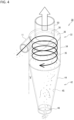
- FIG. 4 is a perspective view illustrating an example of the cyclone separator 30, which is an example of the cyclone separator 30 according to the present invention and the cyclone separator 30 arranged in the fiber waste collection device 1 according to the present invention.
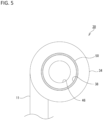
- FIG. 5 is a plan view illustrating an example of the cyclone separator 30.
- FIG. 6 is an example of the front view of the cyclone separator 30.
- FIGS. 4 to 6 also illustrate a connection unit with the fiber waste transfer pipe 11. Note that, in an embodiment according to the present invention, as described above, the cyclone separator 30 includes the first cyclone separator 30a to the fourth cyclone separator 30d, and the first cyclone separator 30a to the fourth cyclone separator 30d all have the same configuration.
- the cyclone separator 30 includes: a body portion 32 in a tubular shape; a tapered portion 42 arranged below the body portion 32; and a fiber waste discharge unit 46 for discharging fiber wastes separated from air to the fiber waste collection container 13 (see FIG. 2 ); and an air discharge unit 50 for discharging air separated from the fiber waste to an exterior.
- the body portion 32 has a tubular portion 34 forming a side wall and a top face portion 36 forming a top end face of the tubular portion 34.
- the top face portion 36 of the body portion 32 is perforated with an opening 38 concentric with the tubular portion 34 smaller in diameter than the tubular portion 34. Note that, the cyclone separator 30 does not completely separate the air and the fiber waste, and the fiber waste obtained after having been separated from the air includes some air. For this reason, not only fiber waste but also unseparated air is discharged from the fiber waste discharge unit 46.
- the tapered portion 42 has a circular top end portion the same in diameter as the tubular portion 34 and a circular bottom end portion smaller in diameter than the circular top end portion.
- the tapered portion 42 has the top end portion and bottom end portion both opened, and has an inclined portion 44 linearly narrowing from the top end portion to the bottom end portion in a front view.
- the inclined portion 44 preferably has an angle ⁇ (hereinafter, referred to as "taper angle ⁇ ”) as an acute angle between a vertical direction and a direction of the inclined portion 44 within a range from 7° to 10° (inclusive of upper and lower limits).
- the top end portion of the tapered portion 42 is connected to a bottom end portion of the tubular portion 34.
- tapered portion 42 corresponds to a "fiber waste transfer portion" according to the present invention.
- the fiber waste discharge unit 46 is in a tubular shape and has both ends opened.
- the inner diameter of the fiber waste discharge unit 46 is the same as that of the bottom end portion of the tapered portion 42.
- the fiber waste discharge unit 46 has a top end portion connected to a bottom end portion of the tapered portion 42 so that they are concentric with each other. Further, the fiber waste discharge unit 46 has a bottom end portion connected to the fiber waste collection container 13 (see FIG. 2 ). There is no partitioning member between the fiber waste discharge unit 46 and the tapered portion 42, and an interior of the fiber waste discharge unit 46 communicates with an interior of the body portion 32.
- the air discharge unit 50 is arranged above the body portion 32.
- the air discharge unit 50 has a tubular member with both ends opened.
- the inner diameter of the air discharge unit 50 is the same as the diameter of the opening 38.
- the air discharge unit 50 has a bottom end portion connected to the opening 38 so that they are concentric with each other. More specifically, the air discharge unit 50 is connected to the body portion 32 such that the tubular portion of the air discharge unit 50 is not within an interior of the body portion 32, and that a bottom end portion of the tubular portion of the air discharge unit 50 and a bottom face of the top face portion 36 of the body portion 32 are flush with each other.
- a lower end portion 50a of the tubular portion of the air discharge unit 50 is preferably above a top end portion 11U of the fiber waste transfer pipe 11. Based upon the findings of the present inventors, if the lower end portion 50a of the tubular portion of the air discharge unit 50 is below the top end portion 11U of the fiber waste transfer pipe 11, the fiber waste is entangled with the tubular portion of the air discharge unit 50, which results in failure of desirable separation of the fiber waste from air.
- the lower end portion 50a of the tubular portion of the air discharge unit 50 is positioned to be higher than at least the top end portion 11U of the fiber waste transfer pipe 11 so as to prevent the fiber waste from being entangled with the tubular portion of the air discharge unit 50, thereby desirably separating the fiber waste and air.
- a bottom end portion of the tubular portion of the air discharge unit 50 and the lower face of the top face portion 36 (see FIG. 4 ) of the body portion 32 are flush with each other. With this configuration, the lower end portion of the tubular portion of the air discharge unit 50 is higher than the top end portion of the fiber waste transfer pipe 11, thereby desirably separating the fiber waste and air.
- the connection positions between the plurality of fiber waste transfer pipes 11 (11a to 11d) and the cyclone separator 30 would be restricted.
- a connection position between the fiber waste transfer pipe 11a, which is one of the plurality of fiber waste transfer pipes 11 (11a to 11d), and the cyclone separator 30 is restricted by the other fiber waste transfer pipes 11b to 11d. Accordingly, it would be difficult to connect one fiber waste transfer pipe 11a to the cyclone separator 30 such that the one fiber waste transfer pipe 11a comes below the bottom end portion of the tubular portion of the air discharge unit 50.
- each of the plurality of fiber waste transfer pipes 11 (11a to 11d) to the cyclone separator 30 on a one-to-one basis makes it possible to connect the fiber waste transfer pipes 11 (11a to 11d) and the cyclone separator 30 at their respective appropriate positions where the fiber waste and air are desirably separated, i.e ., a position where each fiber waste transfer pipe 11 (11a to 11d) is positioned below the bottom end portion of the tubular portion of the air discharge unit 50.
- the air discharge unit 50 There is no partitioning member between the air discharge unit 50 and the body portion 32, and an interior of the air discharge unit 50 communicates with an interior of the body portion 32. Further, based upon the findings of the present inventors, if the inner diameter of the fiber waste discharge unit 46 (i.e., an inner diameter of the bottom end portion of the tapered portion 42) is larger than the inner diameter of the air discharge unit 50 (i.e., the diameter of the opening 38), there is a probability that the fiber waste and air would be insufficiently separated and therefore some fiber wastes would be discharged from the air discharge unit 50.
- the inner diameter of the fiber waste discharge unit 46 i.e., an inner diameter of the bottom end portion of the tapered portion 42
- the inner diameter of the air discharge unit 50 i.e., the diameter of the opening 38
- the inner diameter of the fiber waste discharge unit 46 (i.e., the inner diameter of the bottom end portion of the tapered portion 42) is preferably smaller than the inner diameter of the air discharge unit 50 ( i.e., the diameter of the opening 38).
- both the air discharge unit 50 and the fiber waste discharge unit 46 are in a tubular shape; however, the shape is not limited to this, and a prismatic shape may be adopted.
- an open area of a portion communicating with the interior of the body portion 32 (i.e., a portion connected with the top face portion 36) in the horizontal direction is preferably larger than an open area of the fiber waste discharge unit 46 in the horizontal direction.
- the fiber waste transfer pipe 11 is connected to the body portion 32 at an upper portion of the body portion 32 such that the longitudinal direction of the fiber waste transfer pipe 11 follows an inner peripheral wall 35 of the body portion 32 of the cyclone separator 30.
- the fiber waste transfer pipe 11 is connected to the body portion 32 so as to be tangent to the tubular portion 34 of the body portion 32 of the cyclone separator 30. More specifically, the fiber waste transfer pipe 11 is connected to the body portion 32 of the cyclone separator 30 such that the direction of travel of air containing the fiber waste transferred through the fiber waste transfer pipe 11 follows the inner peripheral wall 35 of the tubular portion 34.
- the air containing the fiber waste transferred through the fiber waste transfer pipe 11 travels in a circumferential direction along the inner peripheral wall 35 of the tubular portion 34.
- the fiber waste contained in the air is, therefore, transferred downward while rotating in the circumferential direction along the inner peripheral wall 35 of the tubular portion 34 due to a centrifugal force, i.e ., a centrifugation action.
- the fiber waste having been caused to travel downward while rotating along the inner peripheral wall 35 of the tubular portion 34 is further transferred toward the fiber waste discharge unit 46 along an inner peripheral wall 45 of the inclined portion 44.
- the fiber waste After having been transferred toward the fiber waste discharge unit 46, the fiber waste is transferred from the fiber waste discharge unit 46 to the fiber waste collection container 13 (see FIG. 2 ). In such a manner, the fiber waste having been transferred through the fiber waste transfer pipe 11 is separated from the air containing the fiber waste, and the separated fiber waste is collected into the fiber waste collection container 13. Meanwhile, the air separated from the fiber waste is discharged from the air discharge unit 50 to an exterior thereof.
- the fiber waste transfer pipes 11 (11a to 11d) and the cyclone separator 30 may be connected at their respective appropriate positions; in addition, the inner peripheral wall 35 of the tubular portion 34 can be secured to ensure that the fiber waste is transferred to the tapered portion 42.
- the fiber Y suctioned from the suction unit 15 is transferred through each fiber waste transfer pipe 11 to be collected as the fiber waste into the fiber waste collection container 13 via the cyclone separator 30 connected to the fiber waste transfer pipe 11.
- the cyclone separator 30 separates the fiber waste from the air transferred through the fiber waste transfer pipes 11.
- the separated fiber waste is collected into the fiber waste collection container 13, and the air separated from the fiber waste is discharged from the air discharge unit 50.
- the cyclone separator 30 thus arranged between each fiber waste transfer pipe 11 and the fiber waste collection container 13, the fiber waste and air are appropriately separated, thereby suppressing discharge of the fiber wastes from the air discharge unit 50 to an exterior thereof.
- the fiber waste transfer pipe 11 is connected to the body portion 32 such that the longitudinal direction thereof follows the inner peripheral wall 35 of the tubular portion 34. Therefore, the air is caused to move in the circumferential direction along the inner peripheral wall 35 of the tubular portion 34 and the fiber waste transferred through the fiber waste transfer pipe 11 is caused to travel downward along the inner peripheral wall 35 of the tubular portion 34 and the inner peripheral wall 45 of the inclined portion 44 due to a centrifugal force, i.e ., a centrifugation action and is separated from the air.
- the fiber waste separated from the air is allowed to pass through the fiber waste discharge unit 46 so as to be collected into the fiber waste collection container 13.
- the clean air obtained after having been separated from the fiber waste is discharged from the air discharge unit 50.
- the air discharge unit 50 is connected to the body portion 32 with their interiors communicating each other such that the air discharge unit 50 is not within an interior of the body portion 32 and that the bottom end portion of the air discharge unit 50 and the top face portion 36 of the body portion 32 are flush with each other. Accordingly, the fiber waste is not entangled with the air discharge unit 50 and the fiber waste and air can be desirably separated.
- the tapered portion 42 includes the inclined portion 44, which decreases in diameter from a point of connection with the body portion 32 toward the fiber waste discharge unit 46. Since the fiber waste and air can be separated in the inclined portion 44, the discharge of the fiber waste from the air discharge unit 50 to an exterior thereof can further be suppressed. Note that, with the above-described inclined portion 44 of a tapered shape having an angle with respect to the vertical direction within a range from 7° to 10° (inclusive of upper and lower limits), the fiber waste and air can be accurately separated and the fiber waste discharge unit 46 can be prevented from being clogged with the fiber waste. As a result, the fiber waste can be desirably discharged from the fiber waste discharge unit 46.
- the inner diameter of the fiber waste discharge unit 46 i.e., the inner diameter of the bottom end portion of the tapered portion 42
- the inner diameter of the air discharge unit 50 i.e., the diameter of the opening 38. Therefore, the fiber waste and air can be desirably separated and discharge of the fiber waste from the air discharge unit 50 to an exterior thereof can be more effectively suppressed.
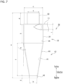
- FIG. 7 is an example of a front view illustrating the cyclone separator 30.
- FIG. 8 is a graph illustrating an example of experiment results indicative of a relationship among a taper angle ⁇ , a flow rate of air in the air discharge unit 50, and a flow rate of air in the fiber waste discharge unit 46.
- the fiber used in EXPERIMENTAL EXAMPLES 1, 2, and 3 below is 75 denier false-twisted yarn.
- the up-and-down direction is defined as a Y-direction, and in particular, an upper direction is defined as a Y-direction on a positive side and a lower direction is defined as a Y-direction on a negative side.
- the flow rate shown in FIG. 8 represents the flow rate of a vector component in the Y-direction. When the value of the flow rate is positive, the air is flowing in the Y-direction on the positive side and when the value of the flow rate is negative, the air is flowing in the Y-direction on the negative side.
- the dimensions of the parts of the cyclone separator 30 are defined as: Y-direction length a of the entire cyclone separator 30; Y-direction length b of the body portion 32; inner diameter c of the body portion 32; Y-direction length d of the air discharge unit 50; inner diameter e of the air discharge unit 50; Y-direction length f of the inclined portion 44; Y-direction length g of the fiber waste discharge unit 46; inner diameter h of the fiber waste discharge unit 46; and taper angle ⁇ .
- i represents the inner diameter of an inlet of the fiber waste transfer pipe 11, which is a connection unit to be connected with the cyclone separator 30.
- TABLE 1 is an example of experiment results showing the relationship between the taper angle ⁇ and the favorability of fiber waste discharge.
- the fiber waste having been formed into a ball and been desirably discharged from the fiber waste discharge unit 46 was judged as "Good”
- the fiber waste having not been formed into a ball and not been discharged from the fiber waste discharge unit 46 was judged as "Bad”
- the fiber waste having been formed into a ball but clogged in the fiber waste discharge unit 46 once out of five times was judged as "Middle”.
- the evaluation was performed at taper angles ⁇ of 10°, 9°, 7°, and 5°.
- the inner diameter h of the fiber waste discharge unit 46 is a dimension determined according to the taper angle ⁇ .
- the air flow velocity within an interior of the fiber waste transfer pipe 11 is assumed to be 1000 m/min, and the mass flow rate of air at the inlet of the fiber waste transfer pipe 11 is 0.014896 kg/s.
- the evaluation results obtained in EXPERIMENT 2 indicate that, assuming that the inner diameter e of the air discharge unit 50 and the inner diameter h of the fiber waste discharge unit 46 have constant sizes, as shown in FIG. 8 , the flow rate of air discharged from the air discharge unit 50 decreases when the flow rate of air discharged from the fiber waste discharge unit 46 increases. Further, the flow rate of air discharged from the air discharge unit 50 decreases as the taper angle ⁇ decreases. On the other hand, at the point of taper angle ⁇ of 7°, the flow rate of air discharged from the fiber waste discharge unit 46 stopped decreasing, and was kept constant even when the taper angle ⁇ was further decreased from 7°.
- the lower limit of the taper angle ⁇ is preferably 7° or more.
- the taper angle ⁇ is preferably in the range of 7° to 10° (inclusive of upper and lower limits).
- EXPERIMENTAL EXAMPLE 3 a relationship between the inner diameter h of the fiber waste discharge unit 46 and the ratio of the flow rate of air discharged from the fiber waste discharge unit 46 to the flow rate of air discharged from the air discharge unit 50 was evaluated. Note that, since the role of the air discharge unit 50 is to discharge the air separated from the fiber waste to an exterior, the inner diameter e of the air discharge unit 50 is fixed at 48 mm, for example. Although the results of the experiment are not shown in the figures, the flow rate (absolute value) of air in the Y-direction at the negative side in the fiber waste discharge unit 46 increases as the inner diameter h of the fiber waste discharge unit 46 increases and decreases as the inner diameter h of the fiber waste discharge unit 46 decreases.
- the air flow rate (absolute value) in the Y-direction at the positive side in the air discharge unit 50 tends to decrease as the inner diameter h of the fiber waste discharge unit 46 increases and tends to increase as the inner diameter h of the fiber waste discharge unit 46 decreases.
- the inner diameter h of the fiber waste discharge unit 46 is preferably smaller than the inner diameter e of the air discharge unit 50. However, it was found that, when the inner diameter h of the fiber waste discharge unit 46 is 27 mm or less, it is difficult to discharge the fiber waste from the fiber waste discharge unit 46.
- the ratio of the flow rate of air discharged from the air discharge unit 50 to the flow rate of air discharged from the fiber waste discharge unit 46 is approximately 7:3. This ratio decreases as the inner diameter h of the fiber waste discharge unit 46 increases. For example, when the inner diameter h of the fiber waste discharge unit 46 is in a range from 27 mm to 35 mm, as the inner diameter h of the fiber waste discharge unit 46 increases, the ratio of the flow rate of air discharged from the air discharge unit 50 to the flow rate of air discharged from the fiber waste discharge unit 46 decreases.
- the ratio of the flow rate of air discharged from the air discharge unit 50 to the flow rate of air discharged from the fiber waste discharge unit 46 is approximately 1:1.
- the inner diameter h of the fiber waste discharge unit 46 is preferably 35 mm or less.
- EXPERIMENTAL EXAMPLE 1 EXPERIMENTAL EXAMPLE 2 and EXPERIMENTAL EXAMPLE 3 are the results of experiments using a 75 denier false-twisted yarn as described above, the present inventors also conducted similar verifications on other fibers.
- the results of these experiments indicate that, for a false-twisted yarn, a polyester fiber, and a polyamide fiber, forming the inclined portion 44 in a tapered shape with the angle with respect to the vertical direction of 7° to 10° (inclusive of upper and lower limits) made it possible to accurately separate the fiber waste and air and prevented the fiber waste discharge unit 46 from being clogged with the fiber waste, which allowed the fiber waste to be desirably discharged from the fiber waste discharge unit 46. It was confirmed that significant results were obtained particularly for 75 to 450 denier false-twisted yarns, a 150 denier PET, and nylon.
- cyclone separator 30 which is an example of the cyclone separator according to the present invention and the cyclone separator arranged in the fiber waste collection device according to the present invention
- fiber waste transferred through the fiber waste transfer pipe 11 together with air is separated from the air, and the separated fiber waste is collected into the fiber waste collection container 13, thus preventing the fiber waste from being discharged to an exterior through the air discharge unit 50.
- Some fiber wastes that were not carried by the flow travelling downward along the inner peripheral wall 35 of the body portion 32 may flow into the air discharge unit 50 and may be discharged through the air discharge unit 50 to an exterior of the cyclone separator 30 ( i.e ., into the atmosphere).
- the cyclone separator according to the present invention and the cyclone separator arranged in the fiber waste collection device according to the present invention are more preferably configured as in a cyclone separator 30A, which is described below as another example of a cyclone separator.
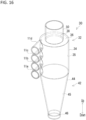
- FIG. 9 is a perspective view illustrating an example of the cyclone separator 30A, which is another example of the cyclone separator according to the present invention and the cyclone separator arranged in the fiber waste collection device 1 according to the present invention.
- the cyclone separator 30A In the following description of the cyclone separator 30A, only the configurations that differ from those of the cyclone separator 30 will be described, and the description of the common configurations to the cyclone separator 30 will be omitted.
- members that are common to the cyclone separator 30 have the same reference signs as those of the cyclone separator 30.
- an upper direction is defined as a Y-direction on a positive side and a lower direction is defined as a Y-direction on a negative side.
- the cyclone separator 30A includes a shielding member 60 with a function of preventing lint, in particular, among the fiber waste flowing into the air discharge unit 50 from the body portion 32 from being discharged to an exterior.
- the shielding member 60 mainly has an outer side member 62 and a partially closed portion 64.
- the outer side member 62 is configured to have a tubular shape so that it can be arranged at radially outer side of the air discharge unit 50, which is a tubular-shaped pipe.
- the gap between the air discharge unit 50 and the outer side member 62 is preferably as small as possible.
- the partially closed portion 64 is provided at one end portion in the axial direction of the outer side member 62 (the direction perpendicular to the diameter direction; the Y direction shown in FIG. 9 ) and is positioned in an opening region 52 of the air discharge unit 50 when the outer side member 62 is arranged at a radially outer side of the air discharge unit 50.
- the opening region 52 is the opening region at the end portion of the tubular air discharge unit 50, i.e., at the boundary between the air discharge unit 50 and an exterior thereof.
- the partially closed portion 64 is configured to partially close the opening region 52 when it is placed in the opening region 52 so that the discharge of lint to an exterior is blocked while maintaining the discharge of air from the air discharge unit 50 to an exterior.
- the partially closed portion 64 has, for example, a plurality of gaps 66 and a grid portion 68.
- the grid portion 68 is formed into a grid-like shape and is provided orthogonally to the Y-direction (positive side), which is the direction of air flow discharged from the air discharge unit 50 to an exterior.
- the air is discharged to an exterior through the plurality of gaps 66.
- the lint is caught by the grid portion 68 and therefore is difficult to be discharged to an exterior.
- the "opening region 52 of the air discharge unit 50" described above corresponds to the "air discharge outlet" of the present invention.
- the partially closed portion 64 may be provided at the end portion in the axial direction of the outer side member 62, and the partially closed portion 64 may be provided at any position in the axial direction of the outer side member 62 as long as it is capable of partially closing the opening region 52 when the outer side member 62 is arranged at a radially outer side of the air discharge unit 50.
- the grid portion 68 it is not indispensable for the grid portion 68 to be provided orthogonally to the direction of air flow, and the grid portion 68 may be provided so that it is inclined with respect to the direction of air flow.
- the partially closed portion 64 may have a portion with a shape of, for example, a mesh-like form, a combination of a grid and a mesh-like form, or any other shape, instead of the grid portion 68 having the grid-like shape.
- the shielding member 60 shown in FIG. 9 is configured to partially close the opening region 52; however, the shielding member 60 is not limited to this form.
- the site partially blocked is not limited to the opening region 52 as long as the lint can be blocked from being discharged to an exterior through the air discharge unit 50.
- the lint can be caught in the path where the lint is transferred when it flows from the body portion 32 into the air discharge unit 50 until it is discharged to an exterior, it is possible to prevent the lint from being discharged to an exterior. Therefore, for example, it may be configured such that the opening 38 (see FIG. 4 ), the lower end portion 50a (see FIG.
- the shielding member 60 is preferably provided to partially close the opening region 52, which is the end of the tubular air discharge unit 50, so that the lint caught by the shielding member 60 can be easily removed.
- the shielding member 60 shown in FIG. 9 can be easily attached to and detached from the air discharge unit 50 by simply arranging the outer side member 62 at a radially outer side of the air discharge unit 50. This allows easy maintenance of the shielding member 60.
- the cyclone separator 30A has a connection member 70 that connects the shielding member 60 to the fiber waste transfer pipe 11.
- This connection member 70 is formed of a chain, for example.
- the shielding member 60 could be lost, for example, if it is blown away by a strong wind or when a worker removes the shielding member 60 from the cyclone separator 30A. Therefore, by connecting the shielding member 60 and the fiber waste transfer pipe 11 with the connection member 70, such a loss of the shielding member 60 can be prevented.
- the connection member 70 is not limited to that for connecting the shielding member 60 to the fiber waste transfer pipes 11, as long as it is capable of preventing the loss of the shielding member 60.
- the connection member 70 may be any member as long as it is capable of connecting an arbitrary member constituting the shielding member 60 and an arbitrary member constituting the cyclone separator 30A.
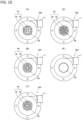
- the open ratio is the ratio of the total area of the plurality of gaps 66 to the open area in the plan view of the opening region 52 (see FIG. 9 ).
- the air discharge unit 50 shown in (E) of FIG. 10 does not have the shielding member 60.
- the plurality of gaps 66 are preferably evenly provided in the opening region 52 (see FIG. 9 ).
- the gaps are not evenly provided in the opening region 52 but are unevenly provided with a bias towards a certain site, this may adversely affect the air flow and the separation of air and fiber waste by the cyclone separator 30A.
- one of the half-circle portions of the opening region 52 which is circular in a plan view, is completely closed and the remaining other half-circle portion is opened, air will flow toward the other half-circle portion. Therefore, it is believed that such an influence on the separation of air and fiber waste can be minimized as much as possible by evenly providing the plurality of gaps 66 in the opening region 52, thereby suppressing the discharge of lint from the air discharge unit 50.
- the flow rate of air discharged from the fiber waste discharge unit 46 is larger than the flow rate of air discharged from the air discharge unit 50, the fiber waste and air will not be desirably separated.
- the shielding member 60 described above when the shielding member 60 described above is provided, the flow rate of air discharged from the air discharge unit 50 to an exterior is lower than that when the shielding member 60 is not provided. Therefore, even if the plurality of gaps 66 are evenly provided, if the flow rate of air discharged from the fiber waste discharge unit 46 exceeds the flow rate of air discharged from the air discharge unit 50, it may adversely affect the separation of air and fiber waste by the cyclone separator 30A. It is to be noted that, when the shielding member 60 is provided, the flow rate of air discharged from the air discharge unit 50 corresponds to the flow rate of air discharged from the shielding member 60.
- FIG. 11 is a graph illustrating an example of experiment results indicative of a relationship between flow rate of air in the air discharge unit 50 and flow rate of air in the fiber waste discharge unit 46.
- the flow rate shown in FIG. 11 represents the flow rate of a vector component in the Y-direction (see FIG. 9 ).
- the value of the flow rate is positive, the air is flowing in the Y-direction on the positive side and when the value of the flow rate is negative, the air is flowing in the Y-direction on the negative side.
- the flow rate of air in the air discharge unit 50 and the flow rate of air in the fiber waste discharge unit 46 were measured while varying the open ratio with respect to the open area in the plan view of the opening region 52 (see FIG. 9 ) to 0%, 20%, 40%, 60%, 80%, and 100%.
- the air flow velocity within an interior of the fiber waste transfer pipe 11 is assumed to be 1000 m/min, and the mass flow rate of air was 0.014896 kg/s, the area flow rate was 0.754768 m 3 /min (0.012579 m 3 /sec), and the density was 1.18415 kg/m 3 at the inlet of the fiber waste transfer pipe 11.
- the flow rate of air in the air discharge unit 50 increases as the open ratio increases. Further, the flow rate (absolute value) of air in the fiber waste discharge unit 46 decreases as the open ratio increases.
- the flow rate (absolute value) of air discharged from the fiber waste discharge unit 46 is larger than the flow rate of air discharged from the air discharge unit 50, the fiber waste and air will not be desirably separated.
- the flow rate of air discharged from the air discharge unit 50 and the flow rate (absolute value) of air discharged from the fiber waste discharge unit 46 are reversed, generally, after the boundary with the open ratio of 40%. Specifically, if the open ratio is 40% or more, the flow rate of air discharged from the air discharge unit 50 is larger than the flow rate (absolute value) of air discharged from the fiber waste discharge unit 46.
- the shielding member 60 preferably has an open ratio of 40% or more at the partially closed portion 64 to ensure desirable separation of fiber waste and air in the cyclotron separator 30A.
- each gap 66 by setting the size of each gap 66 to be larger than a diameter of the lint, an open ratio of 40% or more can be maintained at the partially closed portion 64 while the plurality of gaps 66 can be evenly provided in the opening region 52. Further in other words, if the size of each gap 66 is smaller than a diameter of the lint, there is a probability that desirable separation of lint and air cannot be ensured even by evenly providing the plurality of gaps 66 in the opening region 52.
- the "size of the gap 66" corresponds the maximum size of the gap 66, and therefore, if the gap 66 is in, e.g ., an arc shape as shown in FIG. 10 , the size thereof corresponds to the length along the arc.
- the "maximum size of the gap 66" corresponds to a diameter thereof, or if the gap 66 is in, e.g., an ellipse, the "maximum size of the gap 66" corresponds to the length of a major axis thereof, or if the gap 66 is in, e.g., a parallelogram, the "maximum size of the gap 66" corresponds to the length of a diagonal longer out of two diagonals thereof.
- the shielding member 60 As described above, as a result of configuring the shielding member 60 by setting the size of each gap 66 to be larger than a diameter of the lint while setting the open ratio of the shielding member 60 to 40% or more so as to providing evenly the plurality of gaps 66, the relationship in which the flow rate of air discharged from the air discharge unit 50 is larger than the flow rate of air discharged from the fiber waste discharge unit 46 can be ensured, and as a consequence, desirable separation between fiber waste and air can be maintained, while preventing at least the discharge of lint to an exterior through the air discharge unit 50. Furthermore, it is possible to prevent entanglement of threads discharged to an exterior through the air discharge unit 50 with workers.
- an object to be shielded by the shielding member 60 is in a powdered form (hereinafter, referred to as "powdered substance")
- a powdered form hereinafter, referred to as "powdered substance”
- the size of each gap 66 is set to be larger than a diameter of the powdered substance, there is a probability that the powdered substance, after having been separated from air, would pass through the gap 66, and be discharged to an exterior.
- an object to be shielded by the shielding member 60 in an embodiment according to the present invention, is the lint not only flexible and elastic but also having a length, which is different from the powdered substance.
- Such a lint does not immediately pass through the gap 66 to be discharged to an exterior even if the size of the gap 66 is larger than a diameter of the lint.
- the size of the gap 66 is set to be 20 mm or less. Even if the size of the gap 66 exceeds 20 mm, however, the function of preventing the lint from being discharged to an exterior as a shielding member is attainable by such a gap 66.
- the shielding member 60 is provided to prevent the lint from being discharged from the partially closed portion 64 in the embodiments described above, the lint may be caught outside the air discharge unit 50, for example, as shown in FIG. 12 , as long as the lint is not discharged into the atmosphere through the partially closed portion 64.
- the shielding member 60 is configured such that, when the outer side member 62 is arranged at a radially outer side of the air discharge unit 50, the partially closing portion 64 is positioned at the opening region 52 to partially close the opening region 52. Further, it was described above that such closure of the opening region 52 is not limited to the partial closure, but any configuration that can partially close an arbitrary portion between the lower end portion 50a (see FIG.
- the embodiment in which the opening region 52 is partially closed and the embodiment in which an arbitrary portion between the lower end portion 50a and the opening region 52 is partially closed are both an embodiment in which the region on the interior side ( i.e ., the side opposite to the atmosphere side) from the air discharge unit 50 is closed.
- the lint is caught outside the air discharge unit 50.
- FIG. 12 is a schematic view illustrating a cyclone separator 301 according to the first modified example. Since the cyclone separator 301 differs from the cyclone separator 30A only in the configuration of the shielding member 601, only the configuration of the shielding member 601 is described in the first modified example.
- the components constituting the cyclone separator 301, except for the shielding member 601, are the same as those of the cyclone separators 30 and 30A, and therefore explanation of these components will be omitted and the same reference signs as those of the cyclone separators 30 and 30A are given in FIG. 12 .
- an upper direction is defined as a Y-direction on a positive side and a lower direction is defined as a Y-direction on a negative side.
- the shielding member 601 provided in the cyclone separator 301 shown in FIG. 12 mainly has, as in the shielding member 60 (see FIG. 9 ), an outer side member 621 and a partially closed portion 641.
- the outer side member 621 is configured to have a tubular shape so that it can be arranged at a radially outer side of the air discharge unit 50, which is a tubular-shaped pipe.
- the length in the Y-direction of the outer side member 621 is greater than the length in the Y-direction of the air discharge unit 50. Therefore, when the outer side member 621 is arranged at a radially outer side of the air discharge unit 50, the partially closed portion 641 is not placed in the opening region 52 of the air discharge unit 50; rather, the partially closed portion 641 is placed in an exterior side from the air discharge unit 50. Note that, in FIG.
- the shielding member be provided to prevent lint from being discharged from the air discharge unit 50; instead, the lint may be caught outside the air discharge unit 50 so that the lint will not be discharged into the atmosphere. Even in such a case, the lint that was not carried by the flow toward the fiber waste discharge unit 46 and heads toward the air discharge unit 50 is caught by the partially closed portion 64, thus preventing the lint from being discharged to an exterior via the air discharge unit 50.
- the flow rate of air discharged from the air discharge unit 50 is larger than the flow rate (absolute value) of air discharged from the fiber waste discharge unit 46, and thereby, desirable separation of fiber waste and air as well as prevention of lint from being discharged from the air discharge unit 50 to an exterior can be ensured.
- the flow rate of air discharged from the air discharge unit 50 corresponds to the flow rate of air discharged from the shielding member 60.
- the cyclone separator 30 corresponding to each of the fiber waste transfer pipes 11 (11a to 11d) is provided between each of the plurality of fiber waste transfer pipes 11 (11a to 11d) and one fiber waste collection container 13, but no limitation is intended.
- any one of the embodiments according to the second to fifth modified examples described below can be adopted.
- FIG. 13 is a schematic view illustrating a fiber waste collection device 1A according to a second modified example.
- the fiber waste collection device 1A includes a plurality of fiber waste collection containers 13 (13a to 13d) and a plurality of cyclone separators 30 (30a to 30d) corresponding to each of a plurality of fiber waste transfer pipes 11 (11a to 11d).
- the fiber waste collection container 13 includes a first fiber waste collection container 13a corresponding to the first fiber waste transfer pipe 11a, a second fiber waste collection container 13b corresponding to the second fiber waste transfer pipe 11b, a third fiber waste collection container 13c corresponding to the third fiber waste transfer pipe 11c, and a fourth fiber waste collection container 13d corresponding to the fourth fiber waste transfer pipe 11d.
- the cyclone separator 30 (30a to 30d) includes a first cyclone separator 30a provided between the first fiber waste transfer pipe 11a and the first fiber waste collection container 13a, a second cyclone separator 30b provided between the second fiber waste transfer pipe 11b and the second fiber waste collection container 13b, a third cyclone separator 30c provided between the third fiber waste transfer pipe 11c and the third fiber waste collection container 13c, and a fourth cyclone separator 30d provided between the fourth fiber waste transfer pipe 11d and the fourth fiber waste collection container 13d.
- the first to fourth fiber waste transfer pipes 11a to 11d are each connected to a body portion (no reference sign) such that their longitudinal direction follows an inner peripheral wall (no reference sign) of the body portion (no reference sign) of the cyclone separator 30.
- the first fiber waste transfer pipe 11a to the fourth fiber waste transfer pipe 11d are connected to the body portion of the cyclone separator 30 (30a to 30d) so as to be tangent to a tubular portion of the body portion of the cyclone separator 30 (30a to 30d).
- the fiber waste can be desirably separated from air, the fiber waste can be desirably discharged from the fiber waste discharge unit 46 (see FIG. 4 ), and the air separated from the fiber waste can be desirably discharged from the air discharge unit 50 (see FIG. 4 ).
- FIG. 14 is a schematic view illustrating a fiber waste collection device 1B according to a third modified example.
- the fiber waste collection device 1B includes a plurality of fiber waste transfer pipes 11 (11a to 11d), one fiber waste collection container 13, and one cyclone separator 30.
- the cyclone separator 30 is provided between the plurality of fiber waste transfer pipes 11 (11a to 11d) and the fiber waste collection container 13.
- the plurality of fiber waste transfer pipes 11 (11a to 11d) merge on the upstream side of the cyclone separator 30 and are connected to a body portion (no reference sign) of the cyclone separator 30 such that the longitudinal direction of each pipe after merging follows an inner peripheral wall (no reference sign) of the body portion of the cyclone separator 30.
- the fiber waste transfer pipes 11 are preferably connected to the body portion of the cyclone separator 30 such that the pipe after merging (no reference sign) is tangent to a tubular portion of the body portion of the cyclone separator 30.
- the fiber waste can be desirably separated from air, the fiber waste can be desirably discharged from the fiber waste discharge unit 46 (see FIG. 4 ), and the air separated from the fiber waste can be desirably discharged from the air discharge unit 50 (see FIG. 4 ).
- all of the plurality of fiber waste transfer pipes 11 (11a to 11d) merge on the upstream side of the one cyclone separator 30; however, alternatively, a plurality of cyclone separators 30 may be provided, and two or more of fiber waste transfer pipes from among the plurality of fiber waste transfer pipes 11 (11a to 11d) may merge on the upstream side of the cyclone separators 30.
- two fiber waste transfer pipes may merge on the upstream side of one cyclone separator and may be connected to the one cyclone separator in the merged state, and the remaining two fiber waste transfer pipes may merge on the upstream side of another cyclone separator and may be connected to the another cyclone separator in the merged state.
- FIG. 15 is a plan view of a cyclone separator 30 according to a fourth modified example.
- FIG. 15 also illustrates the air discharge unit 50 for convenience.
- the fiber waste collection device (no reference sign) according to the fourth modified example includes a plurality of fiber waste transfer pipes 11 (11a to 11d), one fiber waste collection container (no reference sign), and one cyclone separator 30. Note that, whereas the plurality of fiber waste transfer pipes 11 (11a to 11d) merge on the upstream side of the cyclone separator 30 in the third modified example, in the fourth modified example, the plurality of fiber waste transfer pipes 11 (11a to 11d) are connected to one cyclone separator 30C instead.
- the first fiber waste transfer pipe 11a, the second fiber waste transfer pipe 11b, the third fiber waste transfer pipe 11c, and the fourth fiber waste transfer pipe 11d are connected at positions shifted in the circumferential direction of the body portion 32 of the one cyclone separator 30.
- the first fiber waste transfer pipe 11a to the fourth fiber waste transfer pipe 11d are each connected to the body portion 32 of the cyclone separator 30 such that their longitudinal direction follows the inner peripheral wall 35 of the body portion 32 of the cyclone separator 30.
- the first fiber waste transfer pipe 11a to the fourth fiber waste transfer pipe 11d are connected to the body portion 32 of the cyclone separator 30 so as to be tangent to the tubular portion 34 of the body portion 32 of the cyclone separator 30.
- the fiber waste can be desirably separated from air
- the fiber waste can be desirably discharged from the fiber waste discharge unit 46
- the air separated from the fiber waste can be desirably discharged from the air discharge unit 50.
- first fiber waste transfer pipe 11a to the fourth fiber waste transfer pipe 11d shown in FIG. 15 are all preferably connected to an upper portion of the body portion 32. However, not all of the first fiber waste transfer pipe 11a to the fourth fiber waste transfer pipe 11d need be provided at the same position in the up-and-down direction and some or all of the first fiber waste transfer pipe 11a to the fourth fiber waste transfer pipe 11d may be connected at positions shifted in the up-and-down direction.
- FIG. 16 is a perspective view of a cyclone separator 30 according to a fifth modified example. Note that, FIG. 16 also illustrates the air discharge unit 50 for convenience. Similar to the fiber waste collection device 1B of the third modified example, the fiber waste collection device (no reference sign) according to the fifth modified example includes a plurality of fiber waste transfer pipes 11 (11a to 11d), one fiber waste collection container (no reference sign), and one cyclone separator 30.
- the first fiber waste transfer pipe 11a, the second fiber waste transfer pipe 11b, the third fiber waste transfer pipe 11c, and the fourth fiber waste transfer pipe 11d are connected at positions shifted in the up-and-down direction of the body portion 32 of the one cyclone separator 30.
- the first fiber waste transfer pipe 11a to the fourth fiber waste transfer pipe 11d are each connected to the body portion 32 of the cyclone separator 30 such that their longitudinal direction follows the inner peripheral wall 35 of the body portion 32 of the cyclone separator 30.
- the first fiber waste transfer pipe 11a to the fourth fiber waste transfer pipe 11d are connected to the body portion 32 of the cyclone separator 30 so as to be tangent to the tubular portion 34 of the body portion 32 of the cyclone separator 30.
- the fiber waste can be desirably separated from air
- the fiber waste can be desirably discharged from the fiber waste discharge unit 46
- the air separated from the fiber waste can be desirably discharged from the air discharge unit 50.
- first fiber waste transfer pipe 11a to the fourth fiber waste transfer pipe 11d shown in FIG. 16 are connected to the body portion 32 at positions shifted from each other in the up-and-down direction but at the same position in the circumferential direction of the body portion 32, no limitation is intended.
- some or all of the first fiber waste transfer pipe 11a to the fourth fiber waste transfer pipe 11d may be connected to the body portion 32 at positions shifted from each other in the circumferential direction of the body portion 32.
- the fiber waste collection device 1 is arranged in the false-twisting machine 101 , but no limitation is intended.
- An embodiment in which the fiber waste collection device 1 is arranged in a textile machine other than the false-twisting machine 101 may also be adopted.
- an embodiment in which the fiber waste collection device 1 is arranged in a spinning machine may also be adopted.
- the winder 107 is arranged in the false-twisting machine 101 in four stages in the up-and-down direction, but no limitation is intended.
- An embodiment in which the winder 107 is arranged in the false-twisting machine 101 in three or less stages or five or more stages in the up-and-down direction may also be adopted.
- the same number of fiber waste transfer pipes 11 as the number of stages of the winders 107 arranged in the up-and-down direction may be provided.
- the air discharge unit 50 has a circularly tubular shape; however, it is sufficient that the air discharge unit 50 has a pipe-like shape and is not limited to a circularly tubular shape.
- the outer side member 62 preferably has a pipe-like shape that can be arranged at a radially outer side of the pipe-like air discharge unit.
- the outer side member 621 if the air discharge unit has a pipe-like shape which is not circularly tubular, the outer side member 621 preferably has a pipe-like shape that can be arranged at a radially outer side of the pipe-like air discharge unit.
Landscapes
- Engineering & Computer Science (AREA)
- Textile Engineering (AREA)
- Mechanical Engineering (AREA)
- Spinning Or Twisting Of Yarns (AREA)
- Preliminary Treatment Of Fibers (AREA)
- Coiling Of Filamentary Materials In General (AREA)
- Separating Particles In Gases By Inertia (AREA)
- Cyclones (AREA)
Abstract
Description
- The present invention relates to a fiber waste collection device that collects fiber wastes separated from air and a false-twisting machine including such a fiber waste collection device.
- In a textile machine such as a false-twisting machine or spinning machine, fiber continues to be supplied even in threading the fiber on the textile machine, or even when replacing a package having the fiber wound on a winder arranged in the textile machine. In textile machines, therefore, it has been customary to suction to collect fiber waste during the yarn-threading or package-replacing operation.
- For example,
Patent Document 1 discloses a suction device for continuously running multi-threads including a suctioning pipe arranged with a plurality of suction ports, a fiber waste collection container connected to an end of the suctioning pipe, and a negative pressure pump or suction blower connected to the fiber waste collection container. In the suction device disclosed inPatent Document 1, the pressure within the suctioning pipe becomes negative due to the operation of the negative pressure pump or suction blower, and the fiber waste suctioned into the suctioning pipe from the plurality of suction ports is suctioned through the suctioning pipe to be collected into the fiber waste collection container. - Patent Document 1:
Japanese Unexamined Patent Application Publication No. H06-40661 - In the suction device disclosed in
Patent Document 1, the fiber waste is suctioned through the suctioning pipe to be collected by the action of the negative pressure pump or the suction blower that are connected to a downstream end side in a suction direction of the suctioning pipe via the fiber waste collection container. In such a suction device, there is a risk that lint would be discharged to an exterior of the suction device together with air. - The present invention has been made in view of the above-described technical problems, and an objective thereof is to provide a fiber waste collection device configured to separate fiber waste from air appropriately thereby capable of suppressing the discharge of lint to an exterior thereof, and a false-twisting machine including the fiber waste collection device.
- A first aspect of the present invention is a fiber waste collection device comprising:
- a fiber waste transfer pipe for transferring fiber waste, including lint, together with air;
- a fiber waste collection unit for collecting the fiber waste transferred through the fiber waste transfer pipe; and
- a cyclone separator provided between the fiber waste transfer pipe and the fiber waste collection unit for separating the fiber waste transferred through the fiber waste transfer pipe from the air and collecting the separated fiber waste into the fiber waste collection unit,
- wherein the cyclone separator includes:
- a fiber waste discharge unit for discharging the fiber waste separated from the air into the fiber waste collection unit together with the air;
- an air discharge unit having a tubular shape for discharging air separated from the fiber waste to an exterior; and
- a shielding member provided at a predetermined site on a path from where the air separated from the fiber waste flows into the air discharge unit to where the air is discharged to the exterior, the shielding member blocking lint that was not discharged from the fiber waste discharge unit and is heading for the air discharge unit from being discharged to the exterior through the air discharge unit,
and - the shielding member has a gap larger than a diameter of the lint, and is configured such that
- a flow rate of air in the air discharge unit is larger than a flow rate of air in the fiber waste discharge unit.
- According to the above-described first aspect of the fiber waste collection device, the fiber waste transferred through the fiber waste transfer pipe is collected into the fiber waste collection unit via the cyclone separator connected to the fiber waste transfer pipe. The cyclone separator separates the fiber (i.e., fiber waste) from the air transferred through the fiber waste transfer pipe. The fiber waste separated from air is collected into the fiber waste collection unit, and the air separated from the fiber waste is discharged to an exterior through the air discharge unit, thereby appropriately separating fiber waste and air. However, some fiber wastes that were not carried by the flow travelling downward along the inner peripheral wall of the body portion may head for the air discharge unit and may be discharged through the air discharge unit to an exterior. In particular, if lint is discharged from the air discharge unit to an exterior, the lint may become entangled with workers, which is undesirable from a safety and sanitary standpoint. In this regard, according to the above-described first aspect of the fiber waste collection device, even if lint is not discharged from the fiber waste discharge unit and heads for the air discharge unit, the lint is blocked by the shielding member and is prevented from being discharged to an exterior through the air discharge unit. Moreover, the shielding member has a gap larger than a diameter of the lint, and is configured such that the flow rate of air in the air discharge unit is larger than the flow rate of air in the fiber waste discharge unit. Therefore, while maintaining desirable separation between the fiber waste and the air, it is possible to prevent lint from being discharged to an exterior and prevent the entanglement of lint discharged to an exterior through the air discharge unit with the workers.
- The expression "provided at a predetermined site on a path from where the air separated from the fiber waste flows into the air discharge unit to where the air is discharged to the exterior" regarding the "shielding member" in the above-described first aspect means that it is sufficient that the lint flowed into the air discharge unit is blocked and prevented from being discharged to an exterior through the air discharge unit. In other words, the shielding member is not limited to being provided at a specific site, for example, an opening at the boundary between the air discharge unit and the exterior (i.e., an opening at the end portion of the air discharge unit).
- In addition, the expression "blocking lint from being discharged to the exterior through the air discharge unit" in the above-described first aspect means, for example, catching lint before it is discharged to the exterior. The "exterior" corresponds to a region outside the components constituting the cyclone separator, such as a region in the atmosphere.
- A second aspect of the present invention is the fiber waste collection device according to the above-described first aspect, which is
- a fiber waste collection device provided in a textile machine for collecting fiber waste generated in the textile machine, wherein
- the cyclone separator preferably includes:
- a body portion having a circular tubular shape and connected with the fiber waste transfer pipe such that a longitudinal direction of the fiber waste transfer pipe follows an inner peripheral wall, the body portion causing the fiber waste transferred through the fiber waste transfer pipe to travel downward along the inner peripheral wall due to a centrifugal force; and
- a fiber waste transfer portion provided below the body portion and between the body portion and the fiber waste discharge unit.
- According to the above-described second aspect of the fiber waste collection device, it is possible to transfer the fiber waste by a centrifugal force along the inner peripheral wall of the tubular body portion to the fiber waste transfer portion that is positioned below, and form the fiber waste into a ball and collect it in the fiber waste collection unit, thereby preventing fiber waste from being discharged to an exterior through the air discharge unit.
- A third aspect of the present invention is the fiber waste collection device, wherein the fiber waste transfer pipe preferably includes a plurality of fiber waste transfer pipes, and the cyclone separator preferably includes a plurality of cyclone separators each arranged for each of the plurality of fiber waste transfer pipes.
- The above-described third aspect of the fiber waste collection device includes a plurality of cyclone separators each arranged for each of the plurality of fiber waste transfer pipes. More specifically, the plurality of fiber waste transfer pipes and the plurality of cyclone separators can be connected on a one-to-one basis, thus connecting the fiber waste transfer pipes and the cyclone separators without having any restrictions imposed by another fiber waste transfer pipe. As a result, the fiber waste transfer pipes and the cyclone separators can be connected at appropriate positions where the fiber waste and air are desirably separated. Note that, the expression "appropriate position" corresponds to, for example, a position where the fiber waste transfer pipes are below the lower end portion of the air discharge unit. Further, when the cyclone separator includes a tubular body portion as in the above-described second aspect of the fiber waste collection device, the inner peripheral wall of the tubular body portion can be ensured and the fiber waste can be securely sent to the lower part of the body portion (or to the fiber waste transfer portion if the fiber waste transfer portion is provided below the body portion). Furthermore, as in the above-described third aspect of the fiber waste collection device, if a plurality of cyclone separators are provided, lint discharged from the air discharge unit of one cyclone separator may become entangled with lint discharged from the air discharge unit of another cyclone separator. In this regard, according to the fiber waste collection device provided, in general, with the above-described first aspect of the shielding members, it is possible to suppress entanglement of lint discharged from the air discharge unit of one cyclone separator with lint discharged from the air discharge unit of another cyclone separator.
- A fourth aspect pf the present invention is the fiber waste collection device, wherein the fiber waste transfer pipe preferably includes a plurality of fiber waste transfer pipes, and the fiber waste collection unit is preferably provided in a number smaller than a number of the plurality of fiber waste transfer pipes.
- According to the above-described fourth aspect of the fiber waste collection device, the number of the fiber waste collection units is smaller than the number of the fiber waste transfer pipes, thus allowing a reduction in the overall size of the fiber waste collection device. In other words, with the cyclone separator, the fiber waste can be made into a ball to be discharged, thereby reducing the volume occupied with the fiber waste within the fiber waste collection unit. Further, by separating the fiber waste from air so as to discharge the air obtained after having been separated from the fiber waste from the air discharge unit, the volume occupied with the air can be reduced in comparison to a method incapable of isolating air used in a conventional fiber waste collection device, for example, having a blower connected to a fiber waste transfer pipe, or the like. As a result, according to the fiber waste collection device of the present invention, a larger amount of fiber waste can be accumulated in the fiber waste collection unit in comparison to a conventional fiber waste collection device, thereby reducing the number of the fiber waste collection units. Further, with such a small number of fiber waste collection units, for example, a frequency of replacement can be reduced, thereby reducing burden on a worker.
- A fifth aspect of the present invention is the fiber waste collection device, wherein the air discharge unit is preferably arranged such that the air discharge unit does not reside within an interior of the body portion and an interior of the air discharge unit communicates with the interior of the body portion.
- According to the above-described fifth aspect of the fiber waste collection device, since the air discharge unit is provided such that it does not reside within an interior of the body portion while communicating with the interior of the body portion, the fiber waste and air can be desirably separated without the fiber waste becoming tangled with the air discharge unit.
- A sixth aspect of the present invention is the fiber waste collection device, wherein the fiber waste transfer portion preferably has an inclined portion with a diameter decreasing from the body portion toward the fiber waste discharge unit.
- According to the above-described sixth aspect of the fiber waste collection device, since the fiber waste and air can be separated in the inclined portion, the discharge of the fiber waste from the air discharge unit to an exterior thereof can further be suppressed.
- A seventh aspect of the present invention is the fiber waste collection device, the fiber waste preferably includes a polyester fiber or a polyamide fiber, and the inclined portion is preferably formed in a tapered shape having an angle formed with respect to a vertical direction within a range of larger than or equal to 7° and smaller than or equal to 10°.
- According to the above-described seventh aspect of the fiber waste collection device, fiber waste and air can be separated more accurately, and the fiber waste discharge unit can be made large enough to discharge the fiber waste, thereby preventing the fiber waste from clogging.
- An eighth aspect of the present invention is the fiber waste collection device, the air discharge unit is preferably configured such that an open area at a portion communicating with an interior of the body portion in a horizontal direction is larger than an open area of the fiber waste discharge unit in the horizontal direction.
- According to the above-described eighth aspect of the fiber waste collection device, the open area of the air discharge unit at a portion communicating with the interior of the body portion in the horizontal direction is made larger than the open area of the fiber waste discharge unit in the horizontal direction, thereby more effectively preventing fiber waste from being discharged to an exterior through the air discharge unit.
- A ninth aspect of the present invention is a false-twisting machine preferably comprising the fiber waste collection device in any one of the above-described first to eighth aspects.
- According to the above-described ninth aspect of the false-twisting machine, while maintaining desirable separation between the fiber waste and the air, it is possible to prevent lint from being discharged to an exterior and prevent the entanglement of lint discharged to an exterior through the air discharge unit with the workers
- It is not indispensable for the fiber waste collection device according to the present invention to include all of the above-described first to eighth aspects of configurations. For example, it is not indispensable for the invention according to the above-described first aspect of the fiber waste collection device to include all of the above-described second to eighth aspects of configurations. Further, the fiber waste collection device according to the present invention may be obtained by arbitrarily combining the above-described first aspect of configuration and any of the above-described second to eighth aspect of configurations to an extent such that consistency can be ensured.
- According to the present invention, it is possible to provide a fiber waste collection device configured to separate fiber waste from air appropriately, thereby capable of suppressing the discharge of lint to an exterior thereof, and a false-twisting machine including the fiber waste collection device.
-
-
FIG. 1 is a schematic view illustrating an example of a false-twisting machine as a textile machine arranged with a fiber waste collection device. -
FIG. 2 is a schematic view illustrating an example of a fiber waste collection device according to an embodiment of the present invention. -
FIG. 3 is a cross-sectional view illustrating an example of a suction unit arranged in a fiber waste transfer pipe. -
FIG. 4 is a perspective view illustrating an example of a cyclone separator. -
FIG. 5 is a plan view illustrating an example of a cyclone separator. -
FIG. 6 is an example of a front view of a cyclone separator. -
FIG. 7 is an example of a front view of a cyclone separator. -
FIG. 8 is a graph illustrating an example of experiment results indicative of a relationship among a taper angle, a flow rate of air in an air discharge unit, and a flow rate of air in a fiber waste discharge unit. -
FIG. 9 is a perspective view illustrating another example of a cyclone separator. -
FIG. 10 is a plan view illustrating a cyclone separator and is also a plan view illustrating an example of variations in open ratio of gap of shielding members. -
FIG. 11 is a graph illustrating an example of experiment results indicative of a relationship between a flow rate of air in an air discharge unit and a flow rate of air in a fiber waste discharge unit. -
FIG. 12 is a schematic view illustrating a cyclone separator according to a first modified example. -
FIG. 13 is a schematic view illustrating a fiber waste collection device according to a second modified example. -
FIG. 14 is a schematic view illustrating a fiber waste collection device according to a third modified example. -
FIG. 15 is a is a plan view illustrating a cyclone separator according to a fourth modified example. -
FIG. 16 is a perspective view illustrating a cyclone separator according to a fifth modified example. - Hereinafter, embodiments of the present invention will be described with reference to the drawings. The present invention can be widely applied to various uses as a fiber waste collection device arranged in a textile machine such as a false-twisting machine so as to collect fiber wastes.
-
FIG. 1 is a schematic view showing a false-twistingmachine 101 as a textile machine arranged with a fiber waste collection device 1 (seeFIG. 2). FIG. 2 is a schematic view showing an example of the fiberwaste collection device 1 according to an embodiment of the present invention. The fiberwaste collection device 1 is arranged in a textile machine, such as the false-twistingmachine 101 or a spinning machine. In an embodiment according to the present invention, the false-twistingmachine 101 will be described as an example of the textile machine in which the fiberwaste collection device 1 is provided. In the following description, initially, the false-twistingmachine 101 arranged with the fiberwaste collection device 1 will be described, and subsequently, the fiberwaste collection device 1 according to an embodiment of the present invention will be described. For the convenience of description, an up-and-down direction, a forward-and-backward direction, and a left-and-right direction in the false-twistingmachine 101 and the fiberwaste collection device 1 are defined as shown inFIGS. 1 and2 . - The false-twisting
machine 101 is configured, as a textile machine, to false-twist thermoplastic synthetic fibers such as polyester and polyamide so as to impart crimps to the false-twisted fibers, thereby producing highly stretchable textured yarns. As shown inFIG. 1 , in the false-twistingmachine 101, amain machine base 102 is arranged so as to extend in an up-and-down direction. Further, the false-twistingmachine 101 includes: ayarn feeding creel 104 arranged so as to face themain machine base 102 across awork space 103 and holding a plurality ofyarn feeding packages 105; a false-twistingdevice 106 arranged above themain machine base 102 so as to false-twist a fiber Y as a yarn supplied from theyarn feeding creel 104; awinder 107 arranged on themain machine base 102 so as to wind the false-twisted fiber Y obtained in the false-twistingdevice 106; and the like. Thewinders 107 are arranged in four stages along the up-and-down direction. Still further, a plurality ofwinders 107 are arranged side by side along a forward-and-backward direction in each of the first to fourth stages. It is to be noted that the forward-and-backward direction in which the plurality ofwinders 107 are arranged in each of the four stages arranged in the up-and-down direction is a direction along a horizontal direction as well as a direction vertical to a direction (left-and-right direction) in which theyarn feeding creel 104 and themain machine base 102 are arranged. - A
first feeding roller 108, ashifter guide 109, afirst heating device 110, and acooling device 111 are arranged in this order from an upstream side in a yarn traveling direction on a yarn path from theyarn feeding creel 104 to the false-twistingdevice 106. Further, asecond feeding roller 112, aninterlace nozzle 113, asecond heating device 114, athird feeding roller 115, and an oilingroller 116 are arranged in this order from an upstream side in a yarn traveling direction on a yarn path from the false-twistingdevice 106 to thewinder 107. - The
first feeding roller 108 is arranged above thework space 103. Thefirst heating device 110 is arranged above thework space 103 and further above thefirst feeding roller 108. Thecooling device 111 is arranged closer to themain machine base 102 than to thefirst heating device 110 above thework space 103. Thefirst heating device 110 and thecooling device 111 are arranged above thework space 103 so as to extend obliquely upward while being separated from themain machine base 102. Theshifter guide 109 is arranged between thefirst feeding roller 108 and thefirst heating device 110 in the up-and-down direction, and is used to pass a fiber Y through thefirst heating device 110 and thecooling device 111 in threading a yarn on the false-twistingmachine 101. - The
second feeding roller 112 is arranged above themain machine base 102. Theinterlace nozzle 113 is arranged above themain machine base 102 and below thesecond feeding roller 112. Thesecond heating device 114 is arranged on themain machine base 102 and is arranged on a back side of thewinder 107 when viewed from thework space 103 so as to extend in the up-and-down direction from the first to fourth stages of the four-stages of thewinders 107. The devices are thus laid out, and a yarn path from theyarn feeding creel 104 to thewinder 107 is formed so as to surround thework space 103. - In the false-twisting
machine 101, the fiber Y as a yarn supplied from theyarn feeding creel 104 passes through the above-described devices and wound on thewinder 107 to form apackage 117. First, the first to third feeding rollers (108, 112, 115) are rollers for feeding the fiber Y from an upstream side to a downstream side in a yarn traveling direction. Each yarn feeding velocity is set so that the yarn feeding velocity of thesecond feeding roller 112 is faster than that of thefirst feeding roller 108. Therefore, the fiber Y is stretched between thefirst feeding roller 108 and thesecond feeding roller 112. Further, each yarn feeding velocity is set so that the yarn feeding velocity of thethird feeding roller 115 is slower than that of thesecond feeding roller 112. Therefore, the fiber Y is loosened between thesecond feeding roller 112 and thethird feeding roller 115. - Then, the fiber Y stretched between the
first feeding roller 108 and thesecond feeding roller 112 is twisted by the false-twistingdevice 106, which is, for example, a friction disk-type twister so as to be carried. The twist formed by the false-twistingdevice 106 propagates to thefirst feeding roller 108, and the fiber Y stretched to be twisted is heated by thefirst heating device 110 and thereafter cooled by thecooling device 111, and thereby, the twist is fixed. After passing through the false-twistingdevice 106, the twisted and heat-set fibers Y are untwisted before reaching thesecond feeding roller 112. - The fibers Y stretched and false-twisted in such a manner are appropriately entangled in the
interlace nozzle 113 so as to have bundling properties; thereafter, the fibers Y are subjected to a relaxation heat treatment in thesecond heating device 114 and wound on a paper tube by thewinder 107 via the oilingroller 116 so as to form thepackage 117. Then, the fully-wound package 117 is removed by a worker from thewinder 107. Then, a new paper tube is attached by a worker to thewinder 107, and a winding operation on the paper tube is restarted. In this way, thepackage 117 is replaced. The fiberwaste collection device 1 of an embodiment according to the present invention is used by being arranged in the false-twistingmachine 101 described above. The fiberwaste collection device 1 of an embodiment according to the present invention is described below. - As shown in
FIG. 2 , the fiberwaste collection device 1 mainly includes, for example, a plurality of fiber waste transfer pipes 11 (11a to 11d), one fiberwaste collection container 13 arranged for the plurality of fiber waste transfer pipes 11 (11a to 11d), and a plurality ofcyclone separators 30 arranged correspondingly to the plurality of fiber waste transfer pipes 11 (11a to 11d). The plurality ofcyclone separators 30 are arranged between the fiber waste transfer pipes 11 (11a to 11d) and the fiberwaste collection container 13. Each of the plurality ofcyclone separators 30 separates fiber wastes from air transferred through each fiberwaste transfer pipe 11 so as to collect the separated fiber wastes into the fiberwaste collection container 13. The details of thecyclone separator 30 will be described later. Note that, the term "fiber waste" above includes thread-like cotton, a relatively short fiber waste, a fiber waste composed of a collection of relatively short fiber wastes, a relatively long lint, and the like. Further, the fiberwaste collection container 13 described above corresponds to a "fiber waste collection unit" according to the present invention. - The fiber
waste collection device 1 is arranged in the false-twistingmachine 101 described above. The plurality of fiberwaste transfer pipes 11 of the fiberwaste collection device 1 are arranged side by side in the up-and-down direction correspondingly to the respective stages of thewinders 107 that are arranged, for example, in four stages, in the false-twistingmachine 101. For this reason, the fiberwaste collection device 1 according to an embodiment of the present invention arranged with such four-stage winders 107 includes four fiber waste transfer pipes 11 (11a to 11d), respectively. Each of the four fiber waste transfer pipes 11 (11a to 11d) is arranged to extend along the forward-and-backward direction. Thewinders 107 are arranged in each of the first to fourth stages ofwinder 107 side by side in the forward-and-backward direction, and the fiber waste transfer pipes 11 (11a to 11d) are also arranged to extend along the forward-and-backward direction in which thewinders 107 are arranged. Each fiber waste transfer pipe 11 (11a to 11d) suctions the fiber Y (seeFIG. 1 ) from regions in proximity to theirrespective winders 107 arranged side by side in the forward-and-backward direction at each of the four stages arranged in the up-and-down direction, and transfers the fiber Y together with air. Each of the four fiber waste transfer pipes 11 (11a to 11d) is connected to the common fiberwaste collection container 13. Further, the air accompanied with the fiber Y transferred through each of the fiber waste transfer pipes 11 (11a to 11d) is separated at thecyclone separator 30 into fiber waste as the fiber Y and clean air obtained after having been separated from the fiber waste. The fiber waste separated from the air is collected in the fiberwaste collection container 13. The clean air obtained after having been separated from the fiber waste is discharged from an air discharge unit 50 (seeFIG. 4 described later) to an exterior thereof. - With the
cyclone separator 30, which is arranged so that the air obtained after having been separated from the fiber waste is discharged from the air discharge unit 50 (seeFIG. 4 described later) to an exterior thereof, the number of the fiberwaste collection containers 13 can be reduced to a smaller number than the number of the fiber waste transfer pipes 11 (11a to 11d), and an overall size of the fiberwaste collection device 1 can be made smaller. In other words, with the cyclone separator, the fiber waste can be made into a ball to be discharged, thereby reducing the volume occupied with the fiber waste within the fiberwaste collection container 13. Further, by separating the fiber waste from air so as to discharge the air obtained after having been separated from the fiber waste from theair discharge unit 50, the volume occupied with the air can be reduced in comparison to a method incapable of isolating air used in a conventional fiber waste collection device, for example, having a blower connected to a fiber waste transfer pipe 11 (11a to 11d), or the like. As a result, according to the fiberwaste collection device 1 of an embodiment according to the present invention, a larger amount of fiber waste can be accumulated in the fiberwaste collection container 13 in comparison to such a conventional fiber waste collection device and thereby, the number of fiberwaste collection containers 13 can be reduced. Further, with such a small number of fiberwaste collection containers 13, for example, a frequency of replacement can be reduced, thereby reducing burden on a worker. Note that, in an embodiment according to the present invention, one fiberwaste collection container 13 is arranged for all of the plurality of fiber waste transfer pipes 11 (11a to 11d); however, the number of the fiberwaste collection containers 13 is not limited as long as the number of the fiberwaste collection containers 13 is smaller than the number of the fiber waste transfer pipes 11 (11a to 11d). - The fiber
waste collection device 1 keeps thread when the thread is changed at thewinder 107 of the false-twistingmachine 101 without cutting the thread so as to collect the thread as fiber waste. In other words, as shown inFIG. 1 , when the fiber Y is threaded on the false-twistingmachine 101 or when thepackage 117 on thewinder 107 of the false-twistingmachine 101 is replaced, the fiberwaste collection device 1 is used in order that: the fiber Y is continuously supplied from theyarn feeding creel 104 to a region in proximity to thewinder 107 via each device (110, 111, 106, 114) so as to be collected as fiber waste from each suction unit. In this manner, when thepackage 117 is replaced at thewinder 107 of the false-twistingmachine 101, the fiber Y supplied continuously in proximity to thewinder 107 can be collected, and therefore, the false-twistingmachine 101 can be continuously operated without any need of cutting the thread. In the following, the configuration of the fiberwaste collection device 1 is described further in detail. - As shown in
FIG. 2 , the plurality ofsuction units 15 configured to suction the fiber Y (seeFIG. 1 ) are arranged in proximity to eachwinder 107, and each of the plurality of fiber waste transfer pipes 11 (11a to 11d) serves as a pipe through which the fiber Y suctioned from the plurality ofsuction units 15 is transferred. Note that, eachsuction unit 15 configured to suction the fiber Y will be described later. Each fiberwaste transfer pipe 11 is formed, for example, in a hollow tubular shape. A plurality of fiber waste transfer pipes 11 (11a to 11d) are arranged and, in an embodiment according to the present invention, four fiberwaste transfer pipes 11 are arranged as described above. - The four fiber waste transfer pipes 11 (11a to 11d) include a first fiber
waste transfer pipe 11a corresponding to a first stage of thewinder 107 as the lowest stage, a second fiberwaste transfer pipe 11b corresponding to a second stage of thewinder 107 above the first stage, a third fiberwaste transfer pipe 11c corresponding to a third stage of thewinder 107 above the second stage, and a fourth fiberwaste transfer pipe 11d corresponding to a fourth stage of thewinder 107 above the third stage. Each of the four fiber waste transfer pipes 11 (11a to 11d) is arranged in the false-twistingmachine 101 such that the longitudinal direction of each of the fiberwaste transfer pipes 11 extends along the forward-and-backward direction. Further, each of the first to fourth fiber waste transfer pipes 11 (11a to 11d) extends along the forward-and-backward direction at each of the first to fourth stages of thewinder 107. Further, in an embodiment according to the present invention, thecyclone separator 30 includes: afirst cyclone separator 30a arranged between the first fiberwaste transfer pipe 11a and the fiberwaste collection container 13; asecond cyclone separator 30b arranged between the second fiberwaste transfer pipe 11b and the fiberwaste collection container 13; athird cyclone separator 30c arranged between the third fiberwaste transfer pipe 11c and the fiberwaste collection container 13; and afourth cyclone separator 30d arranged between the fourth fiberwaste transfer pipe 11d and the fiberwaste collection container 13. - Each of the four fiber waste transfer pipes 11 (11a to 11d) has one closed end portion (backward end portion shown in
FIG. 2 ) in the longitudinal direction extending along the forward-and-backward direction, and the other end portion (forward end portion shown inFIG.2 ) connected to eachcyclone separator 30. - As shown in
FIG. 2 , a plurality ofsuction units 15 are arranged as a mechanism to suction the fibers Y (seeFIG. 1 ). A plurality ofsuction units 15 are arranged in each of the fiber waste transfer pipes 11 (11a to 11d). Each of the plurality ofsuction units 15 arranged in each fiberwaste transfer pipe 11 includes asuction pipe 16 and an opening/closing mechanism 17 (seeFIG. 3 described later), and the plurality ofsuction units 15 are arranged side by side in the longitudinal direction of each fiber waste transfer pipe 11 (11a to 11d). The plurality ofsuction units 15 arranged side by side in each of the fiber waste transfer pipes 11 (11a to 11d) are arranged correspondingly to the plurality ofwinders 107 in each fiber waste transfer pipe 11 (11a to 11d). More specifically, each of the plurality ofsuction units 15 is arranged in each of the fiber waste transfer pipes 11 (11a to 11d) in a position corresponding to each stage of the winders 107 (seeFIG. 1 ), for example, the four stages of thewinders 107 vertically arranged side by side in the forward-and-backward direction in the false-twisting machine 101 (seeFIG. 1 ). - The
suction units 15 arranged in the first to fourth fiber waste transfer pipes 11 (11a to 11d) are configured in a similar manner. Further, the plurality of thesuction units 15 arranged side by side in each of the fiber waste transfer pipes 11 (11a to 11d) are configured in a similar manner. - Each
suction pipe 16 is arranged as a tubular member for suctioning the fiber Y (seeFIG. 1 ) and is smaller in diameter than each of the fiber waste transfer pipes 11 (11a to 11d) so as to extend with a bend in the middle. Eachsuction pipe 16 has one end side communicably connected to each of the fiber waste transfer pipes 11 (11a to 11d) and the other end side arranged with a suction port (not shown) formed in proximity to the winder 107 (seeFIG. 1 ) through which the fiber Y is suctioned. The fiber Y suctioned through the suction port flows into each fiberwaste transfer pipe 11. -
FIG. 3 is a cross-sectional view illustrating an example of thesuction unit 15 arranged in the fiberwaste transfer pipe 11. Note that, inFIG. 3 , the opening/closingmember 19 is in a state of being pushed upward so that asuction port 16a is in an opened state. As shown inFIG. 3 , eachsuction pipe 16 is connected to each of the fiber waste transfer pipes 11 (11a to 11d) in a tilted state. Eachsuction pipe 16 is connected to each fiber waste transfer pipe 11 (11a to 11d) at an acute angle with respect to a direction from upstream (backward side shown inFIG. 3 ) to downstream (forward side shown inFIG. 3 ) of air flow through each fiberwaste transfer pipe 11. In other words, thesuction pipe 16 is connected to the fiber waste transfer pipe 11 (11a to 11d) at an acute angle with respect to a direction from one end portion side (backward side shown inFIG. 3 ) to the other end portion side (forward side shown inFIG. 3 ) connected to the fiberwaste collection container 13. As a result, when the fiber Y (seeFIG.1 ) suctioned from a suction port (not shown) flows into each fiberwaste transfer pipe 11, the fiber Y flows along a direction from upstream to downstream of air flow in the fiberwaste transfer pipe 11. After flowing into each fiberwaste transfer pipe 11, the fiber Y is transferred downstream by air flowing through the fiberwaste transfer pipe 11. - Each
suction pipe 16 includes a compressed airinjection nozzle hole 16d and aguide path 16e. The compressed airinjection nozzle hole 16d is arranged as a nozzle hole for injecting compressed air into eachsuction pipe 16 between one end side arranged with anoutlet opening 16b and the other end side arranged withsuction port 16a. The compressed airinjection nozzle hole 16d is configured to inject compressed air toward the one end side arranged with theoutlet opening 16b within thesuction pipe 16. In an embodiment according to the present invention, two compressed airinjection nozzle holes 16d are arranged. Each of the two compressed airinjection nozzle holes 16d extends from a side arranged with thesuction port 16a toward a side arranged with theoutlet opening 16b as well as from an outer periphery of thesuction pipe 16 toward an inner periphery of thesuction pipe 16, thereby capable of communicating with asuction flow path 16c. With such a configuration, each of the two compressed airinjection nozzle holes 16d is configured to inject compressed air toward the side arranged with theoutlet opening 16b within thesuction pipe 16. Note that, the number of compressed airinjection nozzle holes 16d is not limited to two. - The
guide path 16e of eachsuction pipe 16 is arranged within thesuction pipe 16 as a flow path for compressed air extending annularly along a circumferential direction of thesuction pipe 16. Theguide path 16e communicates with the compressed airinjection nozzle hole 16d and also communicates with acylinder chamber 20, which is described later. The compressed air supplied to thecylinder chamber 20 flows into theguide path 16e and then into the compressed airinjection nozzle hole 16d, and is injected into thesuction flow path 16c. - The
cylinder chamber 20 is configured as a tubular space inside abody portion 18, and is supplied with compressed air. Thecylinder chamber 20 communicates with theguide path 16e of eachsuction pipe 16 via acommunication path 20a arranged within thebody portion 18. Accordingly, the compressed air supplied to thecylinder chamber 20 flows into theguide path 16e to further flow into the compressed airinjection nozzle hole 16d. Further, thecylinder chamber 20 is connected so as to communicate with a compressedair supply pipe 23 for supplying compressed air so that the compressed air is injected from the compressed airinjection nozzle hole 16d of thesuction pipe 16. The compressedair supply pipe 23 is connected to a compressed air supply source (not shown) for supplying compressed air. The compressedair supply pipe 23 is arranged with asolenoid valve 24 for controlling the supply of compressed air to thecylinder chamber 20 by opening and closing thereof so as to enable switching between a communicative state and a shut-off state. When thesolenoid valve 24 is opened, the compressedair supply pipe 23 turns to a communicative state, so that the compressed air is supplied from the compressedair supply pipe 23 to thecylinder chamber 20. When thesolenoid valve 24 is closed, the compressedair supply pipe 23 turns to a shut-off state, so that the supply of the compressed air from the compressedair supply pipe 23 to thecylinder chamber 20 is blocked. - In the
suction unit 15, in a state where thesolenoid valve 24 is closed and the compressedair supply pipe 23 is shut off, and thereby the compressed air is not supplied to thecylinder chamber 20, the opening/closingmember 19 is caused to rotate around a rotatingshaft 29 so as to close thesuction port 16a with the aid of a biasing force applied by aspring member 22 arranged in aspring chamber 25. In this state, an operation of suctioning the fiber Y (seeFIG. 1 ) by thesuction unit 15 is not performed. On the other hand, in a state where thesolenoid valve 24 is opened and the compressedair supply pipe 23 is in communication, and thereby the compressed air is supplied to thecylinder chamber 20, apiston 21 is caused to move upward so as to push the opening/closingmember 19 upward, resulting in opening thesuction port 16a. Further, in a state where the compressed air is supplied to thecylinder chamber 20, the compressed air flows into the compressed airinjection nozzle hole 16d and the compressed air is injected from the compressed airinjection nozzle hole 16d to thesuction flow path 16c of thesuction pipe 16. The compressed air injected to thesuction flow path 16c is injected toward theoutlet opening 16b. In this way, the compressed air injected into thesuction pipe 16 from the compressed airinjection nozzle hole 16d generates air flow within thesuction pipe 16 to transfer the fiber Y toward the fiberwaste transfer pipe 11, and further generates air flow within the fiberwaste transfer pipe 11 to transfer the fiber Y toward the cyclone separator 30 (forward side shown inFIG. 3 ). In such a manner, the fiber Y suctioned from thesuction port 16a can be transferred into the fiberwaste transfer pipe 11. - Note that, the embodiments are not particularly limited as long as the fiber Y (see
FIG. 1 ) can be suctioned from each suction port so that the suctioned fiber Y can be transferred through each of the fiber waste transfer pipes 11 (11a to 11d). For example, the compressed air may be injected into eachsuction pipe 16 as described above, or the pressure within the fiberwaste transfer pipe 11 may be reduced to a negative pressure by suctioning, for example, with a blower. - Further, the air flow velocity in each of the fiber waste transfer pipes 11 (11a to 11d) is preferably 1000 m/min or higher. If the air flow velocity in the fiber
waste transfer pipe 11 is less than 1000 m/min, it is possible to provide a connection unit for supplying the compressed air at end portion (e.g., at a backward end portion) of the fiber waste transfer pipe 11 (11a to 11d), so that the compressed air supplied from a compressed air supply source (not shown) can be supplied to the fiber waste transfer pipe 11 (11a to 11d) from one end portion side of the fiber waste transfer pipe 11 (11a to 11d). Further, a conventionally arranged blower may also be arranged in proximity to thecyclone separator 30 to suction the interior of the fiber waste transfer pipe 11 (11a to 11d), for example, to make up the shortfall to satisfy the required air flow velocity of 1000 m/min. -
FIG. 4 is a perspective view illustrating an example of thecyclone separator 30, which is an example of thecyclone separator 30 according to the present invention and thecyclone separator 30 arranged in the fiberwaste collection device 1 according to the present invention.FIG. 5 is a plan view illustrating an example of thecyclone separator 30.FIG. 6 is an example of the front view of thecyclone separator 30.FIGS. 4 to 6 also illustrate a connection unit with the fiberwaste transfer pipe 11. Note that, in an embodiment according to the present invention, as described above, thecyclone separator 30 includes thefirst cyclone separator 30a to thefourth cyclone separator 30d, and thefirst cyclone separator 30a to thefourth cyclone separator 30d all have the same configuration. - As shown in
FIG. 4 , thecyclone separator 30 includes: abody portion 32 in a tubular shape; a taperedportion 42 arranged below thebody portion 32; and a fiberwaste discharge unit 46 for discharging fiber wastes separated from air to the fiber waste collection container 13 (seeFIG. 2 ); and anair discharge unit 50 for discharging air separated from the fiber waste to an exterior. Thebody portion 32 has atubular portion 34 forming a side wall and atop face portion 36 forming a top end face of thetubular portion 34. Thetop face portion 36 of thebody portion 32 is perforated with anopening 38 concentric with thetubular portion 34 smaller in diameter than thetubular portion 34. Note that, thecyclone separator 30 does not completely separate the air and the fiber waste, and the fiber waste obtained after having been separated from the air includes some air. For this reason, not only fiber waste but also unseparated air is discharged from the fiberwaste discharge unit 46. - The tapered
portion 42 has a circular top end portion the same in diameter as thetubular portion 34 and a circular bottom end portion smaller in diameter than the circular top end portion. The taperedportion 42 has the top end portion and bottom end portion both opened, and has an inclinedportion 44 linearly narrowing from the top end portion to the bottom end portion in a front view. Although the details are described later, theinclined portion 44 preferably has an angle θ (hereinafter, referred to as "taper angle θ") as an acute angle between a vertical direction and a direction of theinclined portion 44 within a range from 7° to 10° (inclusive of upper and lower limits). The top end portion of the taperedportion 42 is connected to a bottom end portion of thetubular portion 34. Further, there is no partitioning member between the taperedportion 42 and thebody portion 32, and an interior of the taperedportion 42 communicates with an interior of thebody portion 32. The "taperedportion 42" corresponds to a "fiber waste transfer portion" according to the present invention. - The fiber
waste discharge unit 46 is in a tubular shape and has both ends opened. The inner diameter of the fiberwaste discharge unit 46 is the same as that of the bottom end portion of the taperedportion 42. The fiberwaste discharge unit 46 has a top end portion connected to a bottom end portion of the taperedportion 42 so that they are concentric with each other. Further, the fiberwaste discharge unit 46 has a bottom end portion connected to the fiber waste collection container 13 (seeFIG. 2 ). There is no partitioning member between the fiberwaste discharge unit 46 and the taperedportion 42, and an interior of the fiberwaste discharge unit 46 communicates with an interior of thebody portion 32. - The
air discharge unit 50 is arranged above thebody portion 32. Theair discharge unit 50 has a tubular member with both ends opened. The inner diameter of theair discharge unit 50 is the same as the diameter of theopening 38. Theair discharge unit 50 has a bottom end portion connected to theopening 38 so that they are concentric with each other. More specifically, theair discharge unit 50 is connected to thebody portion 32 such that the tubular portion of theair discharge unit 50 is not within an interior of thebody portion 32, and that a bottom end portion of the tubular portion of theair discharge unit 50 and a bottom face of thetop face portion 36 of thebody portion 32 are flush with each other. - Note that, as shown in
FIG. 6 , alower end portion 50a of the tubular portion of theair discharge unit 50 is preferably above atop end portion 11U of the fiberwaste transfer pipe 11. Based upon the findings of the present inventors, if thelower end portion 50a of the tubular portion of theair discharge unit 50 is below thetop end portion 11U of the fiberwaste transfer pipe 11, the fiber waste is entangled with the tubular portion of theair discharge unit 50, which results in failure of desirable separation of the fiber waste from air. To address this issue, thelower end portion 50a of the tubular portion of theair discharge unit 50 is positioned to be higher than at least thetop end portion 11U of the fiberwaste transfer pipe 11 so as to prevent the fiber waste from being entangled with the tubular portion of theair discharge unit 50, thereby desirably separating the fiber waste and air. In an embodiment according to the present invention, as shown inFIG. 4 described above, a bottom end portion of the tubular portion of theair discharge unit 50 and the lower face of the top face portion 36 (seeFIG. 4 ) of thebody portion 32 are flush with each other. With this configuration, the lower end portion of the tubular portion of theair discharge unit 50 is higher than the top end portion of the fiberwaste transfer pipe 11, thereby desirably separating the fiber waste and air. - When the plurality of fiber waste transfer pipes 11 (11a to 11d) are connected to a
single cyclone separator 30, the connection positions between the plurality of fiber waste transfer pipes 11 (11a to 11d) and thecyclone separator 30 would be restricted. For example, a connection position between the fiberwaste transfer pipe 11a, which is one of the plurality of fiber waste transfer pipes 11 (11a to 11d), and thecyclone separator 30 is restricted by the other fiberwaste transfer pipes 11b to 11d. Accordingly, it would be difficult to connect one fiberwaste transfer pipe 11a to thecyclone separator 30 such that the one fiberwaste transfer pipe 11a comes below the bottom end portion of the tubular portion of theair discharge unit 50. To address this, connecting each of the plurality of fiber waste transfer pipes 11 (11a to 11d) to thecyclone separator 30 on a one-to-one basis makes it possible to connect the fiber waste transfer pipes 11 (11a to 11d) and thecyclone separator 30 at their respective appropriate positions where the fiber waste and air are desirably separated, i.e., a position where each fiber waste transfer pipe 11 (11a to 11d) is positioned below the bottom end portion of the tubular portion of theair discharge unit 50. - There is no partitioning member between the
air discharge unit 50 and thebody portion 32, and an interior of theair discharge unit 50 communicates with an interior of thebody portion 32. Further, based upon the findings of the present inventors, if the inner diameter of the fiber waste discharge unit 46 (i.e., an inner diameter of the bottom end portion of the tapered portion 42) is larger than the inner diameter of the air discharge unit 50 (i.e., the diameter of the opening 38), there is a probability that the fiber waste and air would be insufficiently separated and therefore some fiber wastes would be discharged from theair discharge unit 50. For this reason, the inner diameter of the fiber waste discharge unit 46 (i.e., the inner diameter of the bottom end portion of the tapered portion 42) is preferably smaller than the inner diameter of the air discharge unit 50 (i.e., the diameter of the opening 38). - Note that, in an embodiment according to the present invention, both the
air discharge unit 50 and the fiberwaste discharge unit 46 are in a tubular shape; however, the shape is not limited to this, and a prismatic shape may be adopted. In this case, an open area of a portion communicating with the interior of the body portion 32 (i.e., a portion connected with the top face portion 36) in the horizontal direction is preferably larger than an open area of the fiberwaste discharge unit 46 in the horizontal direction. - As shown in
FIG. 5 , the fiberwaste transfer pipe 11 is connected to thebody portion 32 at an upper portion of thebody portion 32 such that the longitudinal direction of the fiberwaste transfer pipe 11 follows an innerperipheral wall 35 of thebody portion 32 of thecyclone separator 30. In other words, in a plan view, the fiberwaste transfer pipe 11 is connected to thebody portion 32 so as to be tangent to thetubular portion 34 of thebody portion 32 of thecyclone separator 30. More specifically, the fiberwaste transfer pipe 11 is connected to thebody portion 32 of thecyclone separator 30 such that the direction of travel of air containing the fiber waste transferred through the fiberwaste transfer pipe 11 follows the innerperipheral wall 35 of thetubular portion 34. By connecting the fiberwaste transfer pipe 11 to thecyclone separator 30 in this way, as shown inFIG. 4 , the air containing the fiber waste transferred through the fiberwaste transfer pipe 11 travels in a circumferential direction along the innerperipheral wall 35 of thetubular portion 34. The fiber waste contained in the air is, therefore, transferred downward while rotating in the circumferential direction along the innerperipheral wall 35 of thetubular portion 34 due to a centrifugal force, i.e., a centrifugation action. The fiber waste having been caused to travel downward while rotating along the innerperipheral wall 35 of thetubular portion 34 is further transferred toward the fiberwaste discharge unit 46 along an innerperipheral wall 45 of theinclined portion 44. After having been transferred toward the fiberwaste discharge unit 46, the fiber waste is transferred from the fiberwaste discharge unit 46 to the fiber waste collection container 13 (seeFIG. 2 ). In such a manner, the fiber waste having been transferred through the fiberwaste transfer pipe 11 is separated from the air containing the fiber waste, and the separated fiber waste is collected into the fiberwaste collection container 13. Meanwhile, the air separated from the fiber waste is discharged from theair discharge unit 50 to an exterior thereof. - Note that, by connecting each of the plurality of fiber waste transfer pipes 11 (11a to 11d) to the
cyclone separator 30 on a one-to-one basis, the fiber waste transfer pipes 11 (11a to 11d) and thecyclone separator 30 may be connected at their respective appropriate positions; in addition, the innerperipheral wall 35 of thetubular portion 34 can be secured to ensure that the fiber waste is transferred to the taperedportion 42. - According to the fiber
waste collection device 1 as an embodiment of the present invention, the fiber Y suctioned from thesuction unit 15 is transferred through each fiberwaste transfer pipe 11 to be collected as the fiber waste into the fiberwaste collection container 13 via thecyclone separator 30 connected to the fiberwaste transfer pipe 11. Thecyclone separator 30 separates the fiber waste from the air transferred through the fiberwaste transfer pipes 11. The separated fiber waste is collected into the fiberwaste collection container 13, and the air separated from the fiber waste is discharged from theair discharge unit 50. With thecyclone separator 30 thus arranged between each fiberwaste transfer pipe 11 and the fiberwaste collection container 13, the fiber waste and air are appropriately separated, thereby suppressing discharge of the fiber wastes from theair discharge unit 50 to an exterior thereof. - Further, with the fiber
waste collection device 1 as an embodiment according to the present invention, the fiberwaste transfer pipe 11 is connected to thebody portion 32 such that the longitudinal direction thereof follows the innerperipheral wall 35 of thetubular portion 34. Therefore, the air is caused to move in the circumferential direction along the innerperipheral wall 35 of thetubular portion 34 and the fiber waste transferred through the fiberwaste transfer pipe 11 is caused to travel downward along the innerperipheral wall 35 of thetubular portion 34 and the innerperipheral wall 45 of theinclined portion 44 due to a centrifugal force, i.e., a centrifugation action and is separated from the air. The fiber waste separated from the air is allowed to pass through the fiberwaste discharge unit 46 so as to be collected into the fiberwaste collection container 13. The clean air obtained after having been separated from the fiber waste is discharged from theair discharge unit 50. Theair discharge unit 50 is connected to thebody portion 32 with their interiors communicating each other such that theair discharge unit 50 is not within an interior of thebody portion 32 and that the bottom end portion of theair discharge unit 50 and thetop face portion 36 of thebody portion 32 are flush with each other. Accordingly, the fiber waste is not entangled with theair discharge unit 50 and the fiber waste and air can be desirably separated. - Further, according to the fiber
waste collection device 1 as an embodiment of the present invention, the taperedportion 42 includes theinclined portion 44, which decreases in diameter from a point of connection with thebody portion 32 toward the fiberwaste discharge unit 46. Since the fiber waste and air can be separated in theinclined portion 44, the discharge of the fiber waste from theair discharge unit 50 to an exterior thereof can further be suppressed. Note that, with the above-describedinclined portion 44 of a tapered shape having an angle with respect to the vertical direction within a range from 7° to 10° (inclusive of upper and lower limits), the fiber waste and air can be accurately separated and the fiberwaste discharge unit 46 can be prevented from being clogged with the fiber waste. As a result, the fiber waste can be desirably discharged from the fiberwaste discharge unit 46. - Further, according to the fiber
waste collection device 1 as an embodiment of the present invention, the inner diameter of the fiber waste discharge unit 46 (i.e., the inner diameter of the bottom end portion of the tapered portion 42) is smaller than the inner diameter of the air discharge unit 50 (i.e., the diameter of the opening 38). Therefore, the fiber waste and air can be desirably separated and discharge of the fiber waste from theair discharge unit 50 to an exterior thereof can be more effectively suppressed. - The embodiments according to the present invention were corroborated by the following experimental examples. The results of the experimental examples are described below.
FIG. 7 is an example of a front view illustrating thecyclone separator 30.FIG. 8 is a graph illustrating an example of experiment results indicative of a relationship among a taper angle θ, a flow rate of air in theair discharge unit 50, and a flow rate of air in the fiberwaste discharge unit 46. The fiber used in EXPERIMENTAL EXAMPLES 1, 2, and 3 below is 75 denier false-twisted yarn. - Note that, in
FIGS. 7 and8 , the up-and-down direction is defined as a Y-direction, and in particular, an upper direction is defined as a Y-direction on a positive side and a lower direction is defined as a Y-direction on a negative side. The flow rate shown inFIG. 8 represents the flow rate of a vector component in the Y-direction. When the value of the flow rate is positive, the air is flowing in the Y-direction on the positive side and when the value of the flow rate is negative, the air is flowing in the Y-direction on the negative side. - Further, as shown in
FIG. 7 , the dimensions of the parts of thecyclone separator 30 are defined as: Y-direction length a of theentire cyclone separator 30; Y-direction length b of thebody portion 32; inner diameter c of thebody portion 32; Y-direction length d of theair discharge unit 50; inner diameter e of theair discharge unit 50; Y-direction length f of theinclined portion 44; Y-direction length g of the fiberwaste discharge unit 46; inner diameter h of the fiberwaste discharge unit 46; and taper angle θ. In EXPERIMENTAL EXAMPLE 2 described below, i represents the inner diameter of an inlet of the fiberwaste transfer pipe 11, which is a connection unit to be connected with thecyclone separator 30. - In EXPERIMENTAL EXAMPLE 1, the dimensions of the parts of the
cyclone separator 30 were as follows: a = 280 mm, b = 80 mm, c (inner diameter) = 80 mm, d = 50 mm, e (inner diameter) = 48 mm, g = 10 mm, h (inner diameter) = 31 mm, and the taper angle θ was changed, and the favorability of the fiber waste discharged from the fiber waste discharge unit 46 (hereinafter, referred to as "favorability of fiber waste discharge") was evaluated. The evaluation was performed at taper angles θ of 10°, 15°, 30°, and 40°. Note that, the Y-direction length f of theinclined portion 44 is a dimension determined according to the taper angle θ. - The evaluation results obtained in
EXPERIMENT 1 are shown in TABLE 1. TABLE 1 is an example of experiment results showing the relationship between the taper angle θ and the favorability of fiber waste discharge. To ensure favorable discharge from the fiberwaste discharge unit 46, it is important that the fiber waste be formed into a ball. The fiber waste having been formed into a ball and been desirably discharged from the fiberwaste discharge unit 46 was judged as "Good", the fiber waste having not been formed into a ball and not been discharged from the fiberwaste discharge unit 46 was judged as "Bad", and the fiber waste having been formed into a ball but clogged in the fiberwaste discharge unit 46 once out of five times was judged as "Middle".[TABLE 1] Taper angle θ 10° 15° 30° 45° Favorability of fiber waste discharge Middle Bad Bad Bad - As shown in TABLE 1, when the taper angle θ exceeds 10°, the favorability of fiber waste discharge was judged as "Bad". When the taper angle θ was 10°, in
EXPERIMENT 1, the fiber waste clogged in the fiberwaste discharge unit 46 once of five times, thus being judged as "Middle"; however, since the fiber waste was formed into a ball and was discharged from the fiberwaste discharge unit 46 four out of five times, it is considered close to "Good". Although not shown in TABLE 1, when the taper angle θ was less than 10°, the favorability of fiber waste discharge was judged as "Good" in all cases. - The above evaluation results indicate that a taper angle θ of 10° or less is preferable from the viewpoint of favorability of the fiber waste discharged from the fiber
waste discharge unit 46. - In EXPERIMENTAL EXAMPLE 2, the dimensions of the parts of the
cyclone separator 30 were as follows: a = 300.1 mm, b = 90 mm, c = 90 mm, d = 30 mm, e = 48 mm, f = 170.1 mm, g = 10 mm, i = 21 mm, and only the taper angle θ was changed, and the changes in the flow rate of air in the Y-direction in theair discharge unit 50 and the flow rate of air in the Y-direction in the fiberwaste discharge unit 46 were evaluated. - The evaluation was performed at taper angles θ of 10°, 9°, 7°, and 5°. Note that, the inner diameter h of the fiber
waste discharge unit 46 is a dimension determined according to the taper angle θ. Further, the air flow velocity within an interior of the fiberwaste transfer pipe 11 is assumed to be 1000 m/min, and the mass flow rate of air at the inlet of the fiberwaste transfer pipe 11 is 0.014896 kg/s. - The evaluation results obtained in
EXPERIMENT 2 indicate that, assuming that the inner diameter e of theair discharge unit 50 and the inner diameter h of the fiberwaste discharge unit 46 have constant sizes, as shown inFIG. 8 , the flow rate of air discharged from theair discharge unit 50 decreases when the flow rate of air discharged from the fiberwaste discharge unit 46 increases. Further, the flow rate of air discharged from theair discharge unit 50 decreases as the taper angle θ decreases. On the other hand, at the point of taper angle θ of 7°, the flow rate of air discharged from the fiberwaste discharge unit 46 stopped decreasing, and was kept constant even when the taper angle θ was further decreased from 7°. When the inner diameter e of theair discharge unit 50 and the inner diameter h of the fiberwaste discharge unit 46 were constant with the taper angle θ decreased, the Y-direction length f of theinclined portion 44 increased accordingly. When the Y-direction length f of theinclined portion 44 increases, the Y-direction length a of theentire cyclone separator 30 increases and pressure loss is thought to increase. Accordingly, when the taper angle θ is less than 7°, the ratio of the flow rate of air discharged from the fiberwaste discharge unit 46 to the flow rate of air discharged from theair discharge unit 50 is thought to increase. According to the findings by the present inventors, if the flow rate of air discharged from the fiberwaste discharge unit 46 is larger than the flow rate of air discharged from theair discharge unit 50, the fiber waste and air will not be desirably separated. Therefore, the lower limit of the taper angle θ is preferably 7° or more. - The results of
EXPERIMENTS - In EXPERIMENTAL EXAMPLE 3, a relationship between the inner diameter h of the fiber
waste discharge unit 46 and the ratio of the flow rate of air discharged from the fiberwaste discharge unit 46 to the flow rate of air discharged from theair discharge unit 50 was evaluated. Note that, since the role of theair discharge unit 50 is to discharge the air separated from the fiber waste to an exterior, the inner diameter e of theair discharge unit 50 is fixed at 48 mm, for example. Although the results of the experiment are not shown in the figures, the flow rate (absolute value) of air in the Y-direction at the negative side in the fiberwaste discharge unit 46 increases as the inner diameter h of the fiberwaste discharge unit 46 increases and decreases as the inner diameter h of the fiberwaste discharge unit 46 decreases. On the other hand, the air flow rate (absolute value) in the Y-direction at the positive side in theair discharge unit 50 tends to decrease as the inner diameter h of the fiberwaste discharge unit 46 increases and tends to increase as the inner diameter h of the fiberwaste discharge unit 46 decreases. As described above, according to the findings by the present inventors, the inner diameter h of the fiberwaste discharge unit 46 is preferably smaller than the inner diameter e of theair discharge unit 50. However, it was found that, when the inner diameter h of the fiberwaste discharge unit 46 is 27 mm or less, it is difficult to discharge the fiber waste from the fiberwaste discharge unit 46. Note that, when the inner diameter h of the fiberwaste discharge unit 46 is 27 mm, the ratio of the flow rate of air discharged from theair discharge unit 50 to the flow rate of air discharged from the fiberwaste discharge unit 46 is approximately 7:3. This ratio decreases as the inner diameter h of the fiberwaste discharge unit 46 increases. For example, when the inner diameter h of the fiberwaste discharge unit 46 is in a range from 27 mm to 35 mm, as the inner diameter h of the fiberwaste discharge unit 46 increases, the ratio of the flow rate of air discharged from theair discharge unit 50 to the flow rate of air discharged from the fiberwaste discharge unit 46 decreases. It was also found that, when the inner diameter h of the fiberwaste discharge unit 46 is 35 mm, the ratio of the flow rate of air discharged from theair discharge unit 50 to the flow rate of air discharged from the fiberwaste discharge unit 46 is approximately 1:1. As described above, as the ratio of the flow rate of air discharged from the fiberwaste discharge unit 46 increases relative to the flow rate of air discharged from theair discharge unit 50, separation between the fiber waste and air is not desirably performed. For this reason, the inner diameter h of the fiberwaste discharge unit 46 is preferably 35 mm or less. - Although EXPERIMENTAL EXAMPLE 1, EXPERIMENTAL EXAMPLE 2 and EXPERIMENTAL EXAMPLE 3 are the results of experiments using a 75 denier false-twisted yarn as described above, the present inventors also conducted similar verifications on other fibers. The results of these experiments indicate that, for a false-twisted yarn, a polyester fiber, and a polyamide fiber, forming the
inclined portion 44 in a tapered shape with the angle with respect to the vertical direction of 7° to 10° (inclusive of upper and lower limits) made it possible to accurately separate the fiber waste and air and prevented the fiberwaste discharge unit 46 from being clogged with the fiber waste, which allowed the fiber waste to be desirably discharged from the fiberwaste discharge unit 46. It was confirmed that significant results were obtained particularly for 75 to 450 denier false-twisted yarns, a 150 denier PET, and nylon. - According to the
cyclone separator 30 described above, which is an example of the cyclone separator according to the present invention and the cyclone separator arranged in the fiber waste collection device according to the present invention, fiber waste transferred through the fiberwaste transfer pipe 11 together with air is separated from the air, and the separated fiber waste is collected into the fiberwaste collection container 13, thus preventing the fiber waste from being discharged to an exterior through theair discharge unit 50. Some fiber wastes that were not carried by the flow travelling downward along the innerperipheral wall 35 of thebody portion 32 may flow into theair discharge unit 50 and may be discharged through theair discharge unit 50 to an exterior of the cyclone separator 30 (i.e., into the atmosphere). In particular, when the fiber waste discharged from theair discharge unit 50 to an exterior is lint, the lint may become entangled with workers, which is undesirable from a safety and sanitary standpoint. Furthermore, if a plurality ofcyclone separators 30 are provided, lint discharged from theair discharge unit 50 of onecyclone separator 30 may become entangled with lint discharged from theair discharge unit 50 of anothercyclone separator 30. Therefore, the cyclone separator according to the present invention and the cyclone separator arranged in the fiber waste collection device according to the present invention are more preferably configured as in acyclone separator 30A, which is described below as another example of a cyclone separator. -
FIG. 9 is a perspective view illustrating an example of thecyclone separator 30A, which is another example of the cyclone separator according to the present invention and the cyclone separator arranged in the fiberwaste collection device 1 according to the present invention. In the following description of thecyclone separator 30A, only the configurations that differ from those of thecyclone separator 30 will be described, and the description of the common configurations to thecyclone separator 30 will be omitted. Further, inFIG. 9 , members that are common to thecyclone separator 30 have the same reference signs as those of thecyclone separator 30. Further, inFIG. 9 , as inFIG. 7 , an upper direction is defined as a Y-direction on a positive side and a lower direction is defined as a Y-direction on a negative side. - As shown in
FIG. 9 , thecyclone separator 30A includes a shieldingmember 60 with a function of preventing lint, in particular, among the fiber waste flowing into theair discharge unit 50 from thebody portion 32 from being discharged to an exterior. The shieldingmember 60 mainly has anouter side member 62 and a partially closedportion 64. - The
outer side member 62 is configured to have a tubular shape so that it can be arranged at radially outer side of theair discharge unit 50, which is a tubular-shaped pipe. When theouter side member 62 is arranged at a radially outer side of theair discharge unit 50, the gap between theair discharge unit 50 and theouter side member 62 is preferably as small as possible. - The partially closed
portion 64 is provided at one end portion in the axial direction of the outer side member 62 (the direction perpendicular to the diameter direction; the Y direction shown inFIG. 9 ) and is positioned in anopening region 52 of theair discharge unit 50 when theouter side member 62 is arranged at a radially outer side of theair discharge unit 50. Theopening region 52 is the opening region at the end portion of the tubularair discharge unit 50, i.e., at the boundary between theair discharge unit 50 and an exterior thereof. The partially closedportion 64 is configured to partially close theopening region 52 when it is placed in theopening region 52 so that the discharge of lint to an exterior is blocked while maintaining the discharge of air from theair discharge unit 50 to an exterior. Specifically, the partially closedportion 64 has, for example, a plurality ofgaps 66 and agrid portion 68. Thegrid portion 68 is formed into a grid-like shape and is provided orthogonally to the Y-direction (positive side), which is the direction of air flow discharged from theair discharge unit 50 to an exterior. The air is discharged to an exterior through the plurality ofgaps 66. The lint is caught by thegrid portion 68 and therefore is difficult to be discharged to an exterior. However, the "opening region 52 of theair discharge unit 50" described above corresponds to the "air discharge outlet" of the present invention. - It is not indispensable for the partially closed
portion 64 to be provided at the end portion in the axial direction of theouter side member 62, and the partially closedportion 64 may be provided at any position in the axial direction of theouter side member 62 as long as it is capable of partially closing theopening region 52 when theouter side member 62 is arranged at a radially outer side of theair discharge unit 50. Further, it is not indispensable for thegrid portion 68 to be provided orthogonally to the direction of air flow, and thegrid portion 68 may be provided so that it is inclined with respect to the direction of air flow. Furthermore, it is not indispensable for the partially closedportion 64 to have thegrid portion 68 having the grid-like shape, and the partially closedportion 64 may have a portion with a shape of, for example, a mesh-like form, a combination of a grid and a mesh-like form, or any other shape, instead of thegrid portion 68 having the grid-like shape. - Further, the shielding
member 60 shown inFIG. 9 is configured to partially close theopening region 52; however, the shieldingmember 60 is not limited to this form. Specifically, the site partially blocked is not limited to theopening region 52 as long as the lint can be blocked from being discharged to an exterior through theair discharge unit 50. As long as the lint can be caught in the path where the lint is transferred when it flows from thebody portion 32 into theair discharge unit 50 until it is discharged to an exterior, it is possible to prevent the lint from being discharged to an exterior. Therefore, for example, it may be configured such that the opening 38 (seeFIG. 4 ), thelower end portion 50a (seeFIG. 6 ) of the tubular portion of theair discharge unit 50, and the like, are partially closed. In other words, if it is configured such that an arbitrary portion between thelower end portion 50a of the tubular portion of theair discharge unit 50 and theopening region 52 is partially closed, it is possible to block the lint from being discharged to an exterior through theair discharge unit 50. - However, the shielding
member 60 is preferably provided to partially close theopening region 52, which is the end of the tubularair discharge unit 50, so that the lint caught by the shieldingmember 60 can be easily removed. In particular, the shieldingmember 60 shown inFIG. 9 can be easily attached to and detached from theair discharge unit 50 by simply arranging theouter side member 62 at a radially outer side of theair discharge unit 50. This allows easy maintenance of the shieldingmember 60. - Further, the
cyclone separator 30A has aconnection member 70 that connects the shieldingmember 60 to the fiberwaste transfer pipe 11. Thisconnection member 70 is formed of a chain, for example. The shieldingmember 60 could be lost, for example, if it is blown away by a strong wind or when a worker removes the shieldingmember 60 from thecyclone separator 30A. Therefore, by connecting the shieldingmember 60 and the fiberwaste transfer pipe 11 with theconnection member 70, such a loss of the shieldingmember 60 can be prevented. However, theconnection member 70 is not limited to that for connecting the shieldingmember 60 to the fiberwaste transfer pipes 11, as long as it is capable of preventing the loss of the shieldingmember 60. Theconnection member 70 may be any member as long as it is capable of connecting an arbitrary member constituting the shieldingmember 60 and an arbitrary member constituting thecyclone separator 30A. -
FIG. 10 is a plan view of thecyclone separator 30A and is also a plan view illustrating an example of variations in open ratio of thegap 66 of the partially closedportion 64; the variations are (A) open ratio = 20%, (B) open ratio = 40%, (C) open ratio = 60%, (D) open ratio = 80%, and (E) open ratio = 100%. The open ratio is the ratio of the total area of the plurality ofgaps 66 to the open area in the plan view of the opening region 52 (seeFIG. 9 ). Theair discharge unit 50 shown in (E) ofFIG. 10 does not have the shieldingmember 60. - As shown in (A) to (D) of
FIG. 10 , the plurality ofgaps 66 are preferably evenly provided in the opening region 52 (seeFIG. 9 ). For example, if the gaps are not evenly provided in theopening region 52 but are unevenly provided with a bias towards a certain site, this may adversely affect the air flow and the separation of air and fiber waste by thecyclone separator 30A. For example, if one of the half-circle portions of theopening region 52, which is circular in a plan view, is completely closed and the remaining other half-circle portion is opened, air will flow toward the other half-circle portion. Therefore, it is believed that such an influence on the separation of air and fiber waste can be minimized as much as possible by evenly providing the plurality ofgaps 66 in theopening region 52, thereby suppressing the discharge of lint from theair discharge unit 50. - As described above, if the flow rate of air discharged from the fiber
waste discharge unit 46 is larger than the flow rate of air discharged from theair discharge unit 50, the fiber waste and air will not be desirably separated. On the other hand, when the shieldingmember 60 described above is provided, the flow rate of air discharged from theair discharge unit 50 to an exterior is lower than that when the shieldingmember 60 is not provided. Therefore, even if the plurality ofgaps 66 are evenly provided, if the flow rate of air discharged from the fiberwaste discharge unit 46 exceeds the flow rate of air discharged from theair discharge unit 50, it may adversely affect the separation of air and fiber waste by thecyclone separator 30A. It is to be noted that, when the shieldingmember 60 is provided, the flow rate of air discharged from theair discharge unit 50 corresponds to the flow rate of air discharged from the shieldingmember 60. - Therefore, the following experiment with regard to preferred open ratio in the
cyclone separator 30A of an embodiment according to the present invention was performed. The results of the experimental example are described below with reference toFIG. 11. FIG. 11 is a graph illustrating an example of experiment results indicative of a relationship between flow rate of air in theair discharge unit 50 and flow rate of air in the fiberwaste discharge unit 46. Note that, the flow rate shown inFIG. 11 represents the flow rate of a vector component in the Y-direction (seeFIG. 9 ). When the value of the flow rate is positive, the air is flowing in the Y-direction on the positive side and when the value of the flow rate is negative, the air is flowing in the Y-direction on the negative side. - In this experiment, the flow rate of air in the
air discharge unit 50 and the flow rate of air in the fiberwaste discharge unit 46 were measured while varying the open ratio with respect to the open area in the plan view of the opening region 52 (seeFIG. 9 ) to 0%, 20%, 40%, 60%, 80%, and 100%. Note that, the air flow velocity within an interior of the fiber waste transfer pipe 11 (seeFIGS. 9 and10 ) is assumed to be 1000 m/min, and the mass flow rate of air was 0.014896 kg/s, the area flow rate was 0.754768 m3/min (0.012579 m3/sec), and the density was 1.18415 kg/m3 at the inlet of the fiberwaste transfer pipe 11. - As shown in
FIG. 11 , the flow rate of air in theair discharge unit 50 increases as the open ratio increases. Further, the flow rate (absolute value) of air in the fiberwaste discharge unit 46 decreases as the open ratio increases. - As mentioned in the description above, it was confirmed that if the flow rate (absolute value) of air discharged from the fiber
waste discharge unit 46 is larger than the flow rate of air discharged from theair discharge unit 50, the fiber waste and air will not be desirably separated. As shown inFIG. 11 , the flow rate of air discharged from theair discharge unit 50 and the flow rate (absolute value) of air discharged from the fiberwaste discharge unit 46 are reversed, generally, after the boundary with the open ratio of 40%. Specifically, if the open ratio is 40% or more, the flow rate of air discharged from theair discharge unit 50 is larger than the flow rate (absolute value) of air discharged from the fiberwaste discharge unit 46. In contrast, if the open ratio is less than 40%, the flow rate (absolute value) of air discharged from the fiberwaste discharge unit 46 is larger than the flow rate of air discharged from theair discharge unit 50. Therefore, the shieldingmember 60 preferably has an open ratio of 40% or more at the partially closedportion 64 to ensure desirable separation of fiber waste and air in thecyclotron separator 30A. - In other words, in order to ensure desirable separation of fiber waste and air as well as prevention of lint from being discharged from the
air discharge unit 50 to an exterior, it is necessary to maintain an open ratio of 40% or more at the partially closedportion 64 while evenly providing the plurality ofgaps 66 in theopening region 52. As a result of setting the size of eachgap 66, in particular, to be larger than a diameter of the lint (wire diameter), the flow rate of air discharged from theair discharge unit 50 is larger than the flow rate (absolute value) of air discharged from the fiberwaste discharge unit 46. In other words, by setting the size of eachgap 66 to be larger than a diameter of the lint, an open ratio of 40% or more can be maintained at the partially closedportion 64 while the plurality ofgaps 66 can be evenly provided in theopening region 52. Further in other words, if the size of eachgap 66 is smaller than a diameter of the lint, there is a probability that desirable separation of lint and air cannot be ensured even by evenly providing the plurality ofgaps 66 in theopening region 52. - The "size of the
gap 66" corresponds the maximum size of thegap 66, and therefore, if thegap 66 is in, e.g., an arc shape as shown inFIG. 10 , the size thereof corresponds to the length along the arc. If thegap 66 is in, e.g., a perfect circle, the "maximum size of thegap 66" corresponds to a diameter thereof, or if thegap 66 is in, e.g., an ellipse, the "maximum size of thegap 66" corresponds to the length of a major axis thereof, or if thegap 66 is in, e.g., a parallelogram, the "maximum size of thegap 66" corresponds to the length of a diagonal longer out of two diagonals thereof. - As described above, as a result of configuring the shielding
member 60 by setting the size of eachgap 66 to be larger than a diameter of the lint while setting the open ratio of the shieldingmember 60 to 40% or more so as to providing evenly the plurality ofgaps 66, the relationship in which the flow rate of air discharged from theair discharge unit 50 is larger than the flow rate of air discharged from the fiberwaste discharge unit 46 can be ensured, and as a consequence, desirable separation between fiber waste and air can be maintained, while preventing at least the discharge of lint to an exterior through theair discharge unit 50. Furthermore, it is possible to prevent entanglement of threads discharged to an exterior through theair discharge unit 50 with workers. - In the meantime, when an object to be shielded by the shielding
member 60 is in a powdered form (hereinafter, referred to as "powdered substance"), if the size of eachgap 66 is set to be larger than a diameter of the powdered substance, there is a probability that the powdered substance, after having been separated from air, would pass through thegap 66, and be discharged to an exterior. In contrast to this, an object to be shielded by the shieldingmember 60, in an embodiment according to the present invention, is the lint not only flexible and elastic but also having a length, which is different from the powdered substance. Such a lint does not immediately pass through thegap 66 to be discharged to an exterior even if the size of thegap 66 is larger than a diameter of the lint. In order to set thegap 66 to prevent the lint from passing therethrough or to be hard for the lint to pass therethrough, it is preferable that the size of thegap 66 is set to be 20 mm or less. Even if the size of thegap 66 exceeds 20 mm, however, the function of preventing the lint from being discharged to an exterior as a shielding member is attainable by such agap 66. - Embodiments of the present invention have been described above, but the present invention is not limited to the above-described embodiments and may be subject to various changes within the scope of the claims. For example, the present invention can be changed in the following manner.
- Although the shielding
member 60 is provided to prevent the lint from being discharged from the partially closedportion 64 in the embodiments described above, the lint may be caught outside theair discharge unit 50, for example, as shown inFIG. 12 , as long as the lint is not discharged into the atmosphere through the partially closedportion 64. Specifically, in the embodiments described above, the shieldingmember 60 is configured such that, when theouter side member 62 is arranged at a radially outer side of theair discharge unit 50, the partially closingportion 64 is positioned at theopening region 52 to partially close theopening region 52. Further, it was described above that such closure of theopening region 52 is not limited to the partial closure, but any configuration that can partially close an arbitrary portion between thelower end portion 50a (seeFIG. 6 ) of the tubular portion of theair discharge unit 50 and theopening region 52 may be used. Here, the embodiment in which theopening region 52 is partially closed and the embodiment in which an arbitrary portion between thelower end portion 50a and theopening region 52 is partially closed are both an embodiment in which the region on the interior side (i.e., the side opposite to the atmosphere side) from theair discharge unit 50 is closed. Instead of this embodiment, in the first modified example, the lint is caught outside theair discharge unit 50. -
FIG. 12 is a schematic view illustrating acyclone separator 301 according to the first modified example. Since thecyclone separator 301 differs from thecyclone separator 30A only in the configuration of the shieldingmember 601, only the configuration of the shieldingmember 601 is described in the first modified example. The components constituting thecyclone separator 301, except for the shieldingmember 601, are the same as those of thecyclone separators cyclone separators FIG. 12 . Further, inFIG. 12 , as inFIG. 9 , an upper direction is defined as a Y-direction on a positive side and a lower direction is defined as a Y-direction on a negative side. - The shielding
member 601 provided in thecyclone separator 301 shown inFIG. 12 mainly has, as in the shielding member 60 (seeFIG. 9 ), anouter side member 621 and a partiallyclosed portion 641. - As in the outer side member 62 (see
FIG. 9 ), theouter side member 621 is configured to have a tubular shape so that it can be arranged at a radially outer side of theair discharge unit 50, which is a tubular-shaped pipe. However, the length in the Y-direction of theouter side member 621 is greater than the length in the Y-direction of theair discharge unit 50. Therefore, when theouter side member 621 is arranged at a radially outer side of theair discharge unit 50, the partiallyclosed portion 641 is not placed in theopening region 52 of theair discharge unit 50; rather, the partiallyclosed portion 641 is placed in an exterior side from theair discharge unit 50. Note that, inFIG. 12 , an embodiment in which theouter side member 621 is arranged at a radially outer side of theair discharge unit 50 is represented by a double-dashed line, and an embodiment in which theouter side member 621 is not arranged at a radially outer side of theair discharge unit 50 is represented by a solid line. - As described above, it is not essential that the shielding member be provided to prevent lint from being discharged from the
air discharge unit 50; instead, the lint may be caught outside theair discharge unit 50 so that the lint will not be discharged into the atmosphere. Even in such a case, the lint that was not carried by the flow toward the fiberwaste discharge unit 46 and heads toward theair discharge unit 50 is caught by the partially closedportion 64, thus preventing the lint from being discharged to an exterior via theair discharge unit 50. As a result of setting the size of eachgap 66 to be larger than a diameter of the lint as well as providing evenly a plurality ofgaps 66 in an area through which the air is discharged toward an exterior, the flow rate of air discharged from theair discharge unit 50 is larger than the flow rate (absolute value) of air discharged from the fiberwaste discharge unit 46, and thereby, desirable separation of fiber waste and air as well as prevention of lint from being discharged from theair discharge unit 50 to an exterior can be ensured. It is to be noted that the flow rate of air discharged from theair discharge unit 50 corresponds to the flow rate of air discharged from the shieldingmember 60. - In the embodiments described above, the
cyclone separator 30 corresponding to each of the fiber waste transfer pipes 11 (11a to 11d) is provided between each of the plurality of fiber waste transfer pipes 11 (11a to 11d) and one fiberwaste collection container 13, but no limitation is intended. For example, any one of the embodiments according to the second to fifth modified examples described below can be adopted. -
FIG. 13 is a schematic view illustrating a fiber waste collection device 1A according to a second modified example. As shown inFIG. 13 , in the embodiment of the second modified example, the fiber waste collection device 1A includes a plurality of fiber waste collection containers 13 (13a to 13d) and a plurality of cyclone separators 30 (30a to 30d) corresponding to each of a plurality of fiber waste transfer pipes 11 (11a to 11d). - More specifically, the fiber
waste collection container 13 includes a first fiberwaste collection container 13a corresponding to the first fiberwaste transfer pipe 11a, a second fiberwaste collection container 13b corresponding to the second fiberwaste transfer pipe 11b, a third fiberwaste collection container 13c corresponding to the third fiberwaste transfer pipe 11c, and a fourth fiberwaste collection container 13d corresponding to the fourth fiberwaste transfer pipe 11d. Further, the cyclone separator 30 (30a to 30d) includes afirst cyclone separator 30a provided between the first fiberwaste transfer pipe 11a and the first fiberwaste collection container 13a, asecond cyclone separator 30b provided between the second fiberwaste transfer pipe 11b and the second fiberwaste collection container 13b, athird cyclone separator 30c provided between the third fiberwaste transfer pipe 11c and the third fiberwaste collection container 13c, and afourth cyclone separator 30d provided between the fourth fiberwaste transfer pipe 11d and the fourth fiberwaste collection container 13d. The first to fourth fiberwaste transfer pipes 11a to 11d are each connected to a body portion (no reference sign) such that their longitudinal direction follows an inner peripheral wall (no reference sign) of the body portion (no reference sign) of thecyclone separator 30. In other words, similar to the fiber waste transfer pipes 11 (11a to 11d) described with reference toFIG. 5 , in a plan view, the first fiberwaste transfer pipe 11a to the fourth fiberwaste transfer pipe 11d are connected to the body portion of the cyclone separator 30 (30a to 30d) so as to be tangent to a tubular portion of the body portion of the cyclone separator 30 (30a to 30d). - Even with this embodiment described in the second modified example, the fiber waste can be desirably separated from air, the fiber waste can be desirably discharged from the fiber waste discharge unit 46 (see
FIG. 4 ), and the air separated from the fiber waste can be desirably discharged from the air discharge unit 50 (seeFIG. 4 ). -
FIG. 14 is a schematic view illustrating a fiberwaste collection device 1B according to a third modified example. As shown inFIG. 14 , in the embodiment of the third modified example, the fiberwaste collection device 1B includes a plurality of fiber waste transfer pipes 11 (11a to 11d), one fiberwaste collection container 13, and onecyclone separator 30. - The
cyclone separator 30 is provided between the plurality of fiber waste transfer pipes 11 (11a to 11d) and the fiberwaste collection container 13. The plurality of fiber waste transfer pipes 11 (11a to 11d) merge on the upstream side of thecyclone separator 30 and are connected to a body portion (no reference sign) of thecyclone separator 30 such that the longitudinal direction of each pipe after merging follows an inner peripheral wall (no reference sign) of the body portion of thecyclone separator 30. In other words, similar to the fiberwaste transfer pipes 11 described with reference toFIG. 5 , in a plan view, the fiberwaste transfer pipes 11 are preferably connected to the body portion of thecyclone separator 30 such that the pipe after merging (no reference sign) is tangent to a tubular portion of the body portion of thecyclone separator 30. - Even with this embodiment described in the third modified example, the fiber waste can be desirably separated from air, the fiber waste can be desirably discharged from the fiber waste discharge unit 46 (see
FIG. 4 ), and the air separated from the fiber waste can be desirably discharged from the air discharge unit 50 (seeFIG. 4 ). - Note that, in the embodiment of the third modified example, all of the plurality of fiber waste transfer pipes 11 (11a to 11d) merge on the upstream side of the one
cyclone separator 30; however, alternatively, a plurality ofcyclone separators 30 may be provided, and two or more of fiber waste transfer pipes from among the plurality of fiber waste transfer pipes 11 (11a to 11d) may merge on the upstream side of thecyclone separators 30. For example, two fiber waste transfer pipes may merge on the upstream side of one cyclone separator and may be connected to the one cyclone separator in the merged state, and the remaining two fiber waste transfer pipes may merge on the upstream side of another cyclone separator and may be connected to the another cyclone separator in the merged state. -
FIG. 15 is a plan view of acyclone separator 30 according to a fourth modified example.FIG. 15 also illustrates theair discharge unit 50 for convenience. Similar to the fiberwaste collection device 1B of the third modified example, the fiber waste collection device (no reference sign) according to the fourth modified example includes a plurality of fiber waste transfer pipes 11 (11a to 11d), one fiber waste collection container (no reference sign), and onecyclone separator 30. Note that, whereas the plurality of fiber waste transfer pipes 11 (11a to 11d) merge on the upstream side of thecyclone separator 30 in the third modified example, in the fourth modified example, the plurality of fiber waste transfer pipes 11 (11a to 11d) are connected to one cyclone separator 30C instead. - More specifically, as shown in
FIG. 15 , in the embodiment of the fourth modified example, the first fiberwaste transfer pipe 11a, the second fiberwaste transfer pipe 11b, the third fiberwaste transfer pipe 11c, and the fourth fiberwaste transfer pipe 11d are connected at positions shifted in the circumferential direction of thebody portion 32 of the onecyclone separator 30. The first fiberwaste transfer pipe 11a to the fourth fiberwaste transfer pipe 11d are each connected to thebody portion 32 of thecyclone separator 30 such that their longitudinal direction follows the innerperipheral wall 35 of thebody portion 32 of thecyclone separator 30. In other words, similar to the fiberwaste transfer pipes 11 described with reference toFIG. 5 , in a plan view, the first fiberwaste transfer pipe 11a to the fourth fiberwaste transfer pipe 11d are connected to thebody portion 32 of thecyclone separator 30 so as to be tangent to thetubular portion 34 of thebody portion 32 of thecyclone separator 30. Even with this embodiment described in the fourth modified example, the fiber waste can be desirably separated from air, the fiber waste can be desirably discharged from the fiberwaste discharge unit 46, and the air separated from the fiber waste can be desirably discharged from theair discharge unit 50. - Note that, the first fiber
waste transfer pipe 11a to the fourth fiberwaste transfer pipe 11d shown inFIG. 15 are all preferably connected to an upper portion of thebody portion 32. However, not all of the first fiberwaste transfer pipe 11a to the fourth fiberwaste transfer pipe 11d need be provided at the same position in the up-and-down direction and some or all of the first fiberwaste transfer pipe 11a to the fourth fiberwaste transfer pipe 11d may be connected at positions shifted in the up-and-down direction. -
FIG. 16 is a perspective view of acyclone separator 30 according to a fifth modified example. Note that,FIG. 16 also illustrates theair discharge unit 50 for convenience. Similar to the fiberwaste collection device 1B of the third modified example, the fiber waste collection device (no reference sign) according to the fifth modified example includes a plurality of fiber waste transfer pipes 11 (11a to 11d), one fiber waste collection container (no reference sign), and onecyclone separator 30. - As shown in
FIG. 16 , in the embodiment of the fifth modified example, the first fiberwaste transfer pipe 11a, the second fiberwaste transfer pipe 11b, the third fiberwaste transfer pipe 11c, and the fourth fiberwaste transfer pipe 11d are connected at positions shifted in the up-and-down direction of thebody portion 32 of the onecyclone separator 30. The first fiberwaste transfer pipe 11a to the fourth fiberwaste transfer pipe 11d are each connected to thebody portion 32 of thecyclone separator 30 such that their longitudinal direction follows the innerperipheral wall 35 of thebody portion 32 of thecyclone separator 30. In other words, similar to the fiberwaste transfer pipes 11 described with reference toFIG. 5 , in a plan view, the first fiberwaste transfer pipe 11a to the fourth fiberwaste transfer pipe 11d are connected to thebody portion 32 of thecyclone separator 30 so as to be tangent to thetubular portion 34 of thebody portion 32 of thecyclone separator 30. Even with this embodiment described in the fifth modified example, the fiber waste can be desirably separated from air, the fiber waste can be desirably discharged from the fiberwaste discharge unit 46, and the air separated from the fiber waste can be desirably discharged from theair discharge unit 50. - Note that, while the first fiber
waste transfer pipe 11a to the fourth fiberwaste transfer pipe 11d shown inFIG. 16 are connected to thebody portion 32 at positions shifted from each other in the up-and-down direction but at the same position in the circumferential direction of thebody portion 32, no limitation is intended. For example, some or all of the first fiberwaste transfer pipe 11a to the fourth fiberwaste transfer pipe 11d may be connected to thebody portion 32 at positions shifted from each other in the circumferential direction of thebody portion 32. - In the embodiments described above, an embodiment in which the fiber
waste collection device 1 is arranged in the false-twistingmachine 101 is described, but no limitation is intended. An embodiment in which the fiberwaste collection device 1 is arranged in a textile machine other than the false-twistingmachine 101 may also be adopted. For example, an embodiment in which the fiberwaste collection device 1 is arranged in a spinning machine may also be adopted. - In the embodiments described above, an embodiment in which the
winder 107 is arranged in the false-twistingmachine 101 in four stages in the up-and-down direction is described, but no limitation is intended. An embodiment in which thewinder 107 is arranged in the false-twistingmachine 101 in three or less stages or five or more stages in the up-and-down direction may also be adopted. In this case, the same number of fiberwaste transfer pipes 11 as the number of stages of thewinders 107 arranged in the up-and-down direction may be provided. - In the embodiments described above, an embodiment in which a plurality of fiber
waste transfer pipes 11 are provided is described, but no limitation is intended. An embodiment in which only one fiberwaste transfer pipe 11 is provided may also be adopted. - In the embodiments described above, a case in which the
air discharge unit 50 has a circularly tubular shape is described; however, it is sufficient that theair discharge unit 50 has a pipe-like shape and is not limited to a circularly tubular shape. If the air discharge unit has a pipe-like shape which is not circularly tubular, theouter side member 62 preferably has a pipe-like shape that can be arranged at a radially outer side of the pipe-like air discharge unit. Similarly for theouter side member 621, if the air discharge unit has a pipe-like shape which is not circularly tubular, theouter side member 621 preferably has a pipe-like shape that can be arranged at a radially outer side of the pipe-like air discharge unit. - The embodiments disclosed herein are in all respects illustrative and should not be considered restrictive. The basic scope of the present disclosure is represented not by the above embodiments but by the claims, and is intended to include all modifications within the equivalent meaning and scope of the claims.
-
- 1
- Fiber waste collection device
- 11
- Fiber waste transfer pipe
- 13
- Fiber waste collection container
- 15
- Suction unit
- 30
- Cyclone separator
- 32
- Body portion
- 42
- Tapered portion
- 44
- Inclined portion
- 46
- Fiber waste discharge unit
- 50
- Air discharge unit
- 52
- Opening region
- 60
- Shielding member
- 66
- Gap
- Y
- Fiber
Claims (9)
- A fiber waste collection device comprising:a fiber waste transfer pipe (11) for transferring fiber waste, including lint, together with air;a fiber waste collection unit (13) for collecting the fiber waste transferred through the fiber waste transfer pipe (11); anda cyclone separator (30A, 301) provided between the fiber waste transfer pipe (11) and the fiber waste collection unit (13) for separating the fiber waste transferred through the fiber waste transfer pipe (11) from the air and collecting the separated fiber waste into the fiber waste collection unit (13),whereinthe cyclone separator (30A, 301) includes:a fiber waste discharge unit (46) for discharging the fiber waste separated from the air into the fiber waste collection unit (13) together with the air;an air discharge unit (50) having a tubular shape for discharging air separated from the fiber waste to an exterior; anda shielding member (60) provided at a predetermined site on a path from where the air separated from the fiber waste flows into the air discharge unit (50) to where the air is discharged to the exterior, the shielding member (60) blocking lint that was not discharged from the fiber waste discharge unit (46) and is heading for the air discharge unit (50) from being discharged to the exterior through the air discharge unit (50),
andthe shielding member (60) has a gap larger than a diameter of the lint, and is configured such thata flow rate of air in the air discharge unit (50) is larger than a flow rate of air in the fiber waste discharge unit (46). - The fiber waste collection device as claimed in claim 1, which is a fiber waste collection device provided in a textile machine for collecting fiber waste generated in the textile machine, wherein
the cyclone separator (30A, 301) includes:a body portion having a circular tubular shape and connected with the fiber waste transfer pipe (11) such that a longitudinal direction of the fiber waste transfer pipe (11) follows an inner peripheral wall, the body portion causing the fiber waste transferred through the fiber waste transfer pipe (11) to travel downward along the inner peripheral wall due to a centrifugal force; anda fiber waste transfer portion provided below the body portion and between the body portion and the fiber waste discharge unit (46). - The fiber waste collection device as claimed in claim 1 or 2, whereinthe fiber waste transfer pipe (11) includes a plurality of fiber waste transfer pipes (11), andthe cyclone separator (30A, 301) includes a plurality of cyclone separators (30A, 301) each arranged for each of the plurality of fiber waste transfer pipes (11).
- The fiber waste collection device as claimed in any one of claims 1 to 3, whereinthe fiber waste transfer pipe (11) includes a plurality of fiber waste transfer pipes (11), andthe fiber waste collection unit (13) is provided in a number smaller than a number of the plurality of fiber waste transfer pipes (11).
- The fiber waste collection device as claimed in claim 2, whereinthe air discharge unit (50) is arranged such thatthe air discharge unit (50) does not reside within an interior of the body portion and an interior of the air discharge unit (50) communicates with the interior of the body portion.
- The fiber waste collection device as claimed in claim 2, wherein
the fiber waste transfer portion has an inclined portion with a diameter decreasing from the body portion toward the fiber waste discharge unit (46). - The fiber waste collection device as claimed in claim 6, whereinthe fiber waste includes a polyester fiber or a polyamide fiber, andthe inclined portion is formed in a tapered shape having an angle formed with respect to a vertical direction within a range of larger than or equal to 7° and smaller than or equal to 10°.
- The fiber waste collection device as claimed in claim 6 or 7, wherein
the air discharge unit (50) is configured such that an open area at a portion communicating with an interior of the body portion in a horizontal direction is larger than an open area of the fiber waste discharge unit (46) in the horizontal direction. - A false-twisting machine comprising the fiber waste collection device as claimed in any one of claims 1 to 8.
Applications Claiming Priority (1)
| Application Number | Priority Date | Filing Date | Title |
|---|---|---|---|
| JP2023088774 | 2023-05-30 |
Publications (1)
| Publication Number | Publication Date |
|---|---|
| EP4471197A1 true EP4471197A1 (en) | 2024-12-04 |
Family
ID=91226721
Family Applications (1)
| Application Number | Title | Priority Date | Filing Date |
|---|---|---|---|
| EP24177248.2A Pending EP4471197A1 (en) | 2023-05-30 | 2024-05-22 | Fiber waste collection device and false-twisting machine |
Country Status (4)
| Country | Link |
|---|---|
| EP (1) | EP4471197A1 (en) |
| JP (1) | JP2024173760A (en) |
| CN (1) | CN119061543A (en) |
| TW (1) | TW202447012A (en) |
Citations (4)
| Publication number | Priority date | Publication date | Assignee | Title |
|---|---|---|---|---|
| JPH0640661A (en) | 1992-04-11 | 1994-02-15 | Barmag Ag | Suction unit for a number of threads running continuously |
| WO2005049464A1 (en) * | 2003-11-19 | 2005-06-02 | Saurer Gmbh & Co. Kg | False twist texturing machine |
| EP2045378A1 (en) * | 2007-10-04 | 2009-04-08 | Murata Machinery, Ltd. | Dust collecting and processing system in textile machine |
| EP2653423B1 (en) * | 2012-04-18 | 2015-07-15 | Savio Macchine Tessili S.p.A. | Separation device of dust from pieces of yarn for the collection and recovery of winding waste and winding machine wih such device |
-
2024
- 2024-05-10 CN CN202410573638.8A patent/CN119061543A/en active Pending
- 2024-05-17 TW TW113118255A patent/TW202447012A/en unknown
- 2024-05-22 EP EP24177248.2A patent/EP4471197A1/en active Pending
- 2024-05-27 JP JP2024085319A patent/JP2024173760A/en active Pending
Patent Citations (4)
| Publication number | Priority date | Publication date | Assignee | Title |
|---|---|---|---|---|
| JPH0640661A (en) | 1992-04-11 | 1994-02-15 | Barmag Ag | Suction unit for a number of threads running continuously |
| WO2005049464A1 (en) * | 2003-11-19 | 2005-06-02 | Saurer Gmbh & Co. Kg | False twist texturing machine |
| EP2045378A1 (en) * | 2007-10-04 | 2009-04-08 | Murata Machinery, Ltd. | Dust collecting and processing system in textile machine |
| EP2653423B1 (en) * | 2012-04-18 | 2015-07-15 | Savio Macchine Tessili S.p.A. | Separation device of dust from pieces of yarn for the collection and recovery of winding waste and winding machine wih such device |
Also Published As
| Publication number | Publication date |
|---|---|
| CN119061543A (en) | 2024-12-03 |
| JP2024173760A (en) | 2024-12-12 |
| TW202447012A (en) | 2024-12-01 |
Similar Documents
| Publication | Publication Date | Title |
|---|---|---|
| CN103781951B (en) | Apparatus and method for producing knitwear | |
| JP4310061B2 (en) | Equipment for producing core yarn | |
| US10683188B2 (en) | Method for operating a textile machine, and textile machine for producing roving | |
| JPH08510019A (en) | Method and apparatus for producing mixed yarn and mixed yarn | |
| CN100360389C (en) | Broken end suction device | |
| CN103014931A (en) | Pneumatic spinning device, spinning unit, spinning machine, and pneumatic spinning method | |
| EP4345199A1 (en) | False-twisting machine and fiber waste collection device | |
| US20030121247A1 (en) | Pneumatic spinning apparatus and spinning method | |
| CN108394760A (en) | Yarn splicing device connects yarn prism and the inlay for connecing yarn prism | |
| CN101809214B (en) | Apparatus for transporting fibre material between a drafting arrangement and a mesh-forming machine, and circular knitting machine equipped with said apparatus | |
| CN1871381A (en) | Air-jet spinning device | |
| EP4471196B1 (en) | Fiber waste collection device and false-twisting machine | |
| CN101622386B (en) | Machine for the production of a knitted fabric made of fiber material | |
| JP2024173760A (en) | Fiber waste recovery equipment and false twist processing machine | |
| EP4556609A1 (en) | Fiber waste collection device and false-twisting machine | |
| US4768336A (en) | Arrangement for pneumatic false-twist spinning | |
| JP4980719B2 (en) | False twisting machine | |
| EP4343042A1 (en) | Fiber waste collection device | |
| JP2019525017A (en) | Method for processing strip-shaped fiber assembly and roving machine | |
| CN106245164A (en) | Weaving loom | |
| JP2000273735A (en) | Fluid treatment equipment | |
| KR20110018029A (en) | Winding interlock device for multi-end fiber filament | |
| HK1146492A (en) | Apparatus for transporting fibre material between a drafting arrangement and a mesh-forming machine, and circular knitting machine equipped with said apparatus | |
| JPS6321945A (en) | Yarn interlacing apparatus | |
| CN110431098A (en) | Fiber Machinery |
Legal Events
| Date | Code | Title | Description |
|---|---|---|---|
| PUAI | Public reference made under article 153(3) epc to a published international application that has entered the european phase |
Free format text: ORIGINAL CODE: 0009012 |
|
| STAA | Information on the status of an ep patent application or granted ep patent |
Free format text: STATUS: THE APPLICATION HAS BEEN PUBLISHED |
|
| AK | Designated contracting states |
Kind code of ref document: A1 Designated state(s): AL AT BE BG CH CY CZ DE DK EE ES FI FR GB GR HR HU IE IS IT LI LT LU LV MC ME MK MT NL NO PL PT RO RS SE SI SK SM TR |
|
| STAA | Information on the status of an ep patent application or granted ep patent |
Free format text: STATUS: REQUEST FOR EXAMINATION WAS MADE |
|
| 17P | Request for examination filed |
Effective date: 20250604 |
|
| STAA | Information on the status of an ep patent application or granted ep patent |
Free format text: STATUS: EXAMINATION IS IN PROGRESS |
|
| 17Q | First examination report despatched |
Effective date: 20250917 |
|
| GRAP | Despatch of communication of intention to grant a patent |
Free format text: ORIGINAL CODE: EPIDOSNIGR1 |
|
| STAA | Information on the status of an ep patent application or granted ep patent |
Free format text: STATUS: GRANT OF PATENT IS INTENDED |
|
| INTG | Intention to grant announced |
Effective date: 20260402 |