EP4470967A1 - Improved ammonia production process - Google Patents
Improved ammonia production process Download PDFInfo
- Publication number
- EP4470967A1 EP4470967A1 EP23201425.8A EP23201425A EP4470967A1 EP 4470967 A1 EP4470967 A1 EP 4470967A1 EP 23201425 A EP23201425 A EP 23201425A EP 4470967 A1 EP4470967 A1 EP 4470967A1
- Authority
- EP
- European Patent Office
- Prior art keywords
- stream
- hydrogen
- ammonia
- producing
- steam
- Prior art date
- Legal status (The legal status is an assumption and is not a legal conclusion. Google has not performed a legal analysis and makes no representation as to the accuracy of the status listed.)
- Pending
Links
Images


Classifications
-
- C—CHEMISTRY; METALLURGY
- C01—INORGANIC CHEMISTRY
- C01B—NON-METALLIC ELEMENTS; COMPOUNDS THEREOF; METALLOIDS OR COMPOUNDS THEREOF NOT COVERED BY SUBCLASS C01C
- C01B3/00—Hydrogen; Gaseous mixtures containing hydrogen; Separation of hydrogen from mixtures containing it; Purification of hydrogen; Reversible storage of hydrogen
- C01B3/02—Production of hydrogen; Production of gaseous mixtures containing hydrogen
- C01B3/025—Preparation or purification of gas mixtures for ammonia synthesis
-
- C—CHEMISTRY; METALLURGY
- C01—INORGANIC CHEMISTRY
- C01B—NON-METALLIC ELEMENTS; COMPOUNDS THEREOF; METALLOIDS OR COMPOUNDS THEREOF NOT COVERED BY SUBCLASS C01C
- C01B3/00—Hydrogen; Gaseous mixtures containing hydrogen; Separation of hydrogen from mixtures containing it; Purification of hydrogen; Reversible storage of hydrogen
- C01B3/02—Production of hydrogen; Production of gaseous mixtures containing hydrogen
- C01B3/32—Production of hydrogen; Production of gaseous mixtures containing hydrogen by reaction of gaseous or liquid organic compounds with gasifying agents, e.g. water, carbon dioxide or air
- C01B3/34—Production of hydrogen; Production of gaseous mixtures containing hydrogen by reaction of gaseous or liquid organic compounds with gasifying agents, e.g. water, carbon dioxide or air by reaction of hydrocarbons with gasifying agents
- C01B3/38—Production of hydrogen; Production of gaseous mixtures containing hydrogen by reaction of gaseous or liquid organic compounds with gasifying agents, e.g. water, carbon dioxide or air by reaction of hydrocarbons with gasifying agents using catalysts
- C01B3/382—Processes with two or more reaction steps, of which at least one is catalytic, e.g. steam reforming and partial oxidation
-
- C—CHEMISTRY; METALLURGY
- C01—INORGANIC CHEMISTRY
- C01B—NON-METALLIC ELEMENTS; COMPOUNDS THEREOF; METALLOIDS OR COMPOUNDS THEREOF NOT COVERED BY SUBCLASS C01C
- C01B3/00—Hydrogen; Gaseous mixtures containing hydrogen; Separation of hydrogen from mixtures containing it; Purification of hydrogen; Reversible storage of hydrogen
- C01B3/02—Production of hydrogen; Production of gaseous mixtures containing hydrogen
- C01B3/06—Production of hydrogen; Production of gaseous mixtures containing hydrogen by reaction of inorganic compounds containing electro-positively bound hydrogen with inorganic reducing agents
- C01B3/12—Production of hydrogen; Production of gaseous mixtures containing hydrogen by reaction of inorganic compounds containing electro-positively bound hydrogen with inorganic reducing agents by reaction of water vapour with carbon monoxide
- C01B3/16—Production of hydrogen; Production of gaseous mixtures containing hydrogen by reaction of inorganic compounds containing electro-positively bound hydrogen with inorganic reducing agents by reaction of water vapour with carbon monoxide using catalysts
-
- C—CHEMISTRY; METALLURGY
- C01—INORGANIC CHEMISTRY
- C01B—NON-METALLIC ELEMENTS; COMPOUNDS THEREOF; METALLOIDS OR COMPOUNDS THEREOF NOT COVERED BY SUBCLASS C01C
- C01B3/00—Hydrogen; Gaseous mixtures containing hydrogen; Separation of hydrogen from mixtures containing it; Purification of hydrogen; Reversible storage of hydrogen
- C01B3/02—Production of hydrogen; Production of gaseous mixtures containing hydrogen
- C01B3/32—Production of hydrogen; Production of gaseous mixtures containing hydrogen by reaction of gaseous or liquid organic compounds with gasifying agents, e.g. water, carbon dioxide or air
- C01B3/34—Production of hydrogen; Production of gaseous mixtures containing hydrogen by reaction of gaseous or liquid organic compounds with gasifying agents, e.g. water, carbon dioxide or air by reaction of hydrocarbons with gasifying agents
- C01B3/38—Production of hydrogen; Production of gaseous mixtures containing hydrogen by reaction of gaseous or liquid organic compounds with gasifying agents, e.g. water, carbon dioxide or air by reaction of hydrocarbons with gasifying agents using catalysts
-
- C—CHEMISTRY; METALLURGY
- C01—INORGANIC CHEMISTRY
- C01B—NON-METALLIC ELEMENTS; COMPOUNDS THEREOF; METALLOIDS OR COMPOUNDS THEREOF NOT COVERED BY SUBCLASS C01C
- C01B3/00—Hydrogen; Gaseous mixtures containing hydrogen; Separation of hydrogen from mixtures containing it; Purification of hydrogen; Reversible storage of hydrogen
- C01B3/02—Production of hydrogen; Production of gaseous mixtures containing hydrogen
- C01B3/32—Production of hydrogen; Production of gaseous mixtures containing hydrogen by reaction of gaseous or liquid organic compounds with gasifying agents, e.g. water, carbon dioxide or air
- C01B3/34—Production of hydrogen; Production of gaseous mixtures containing hydrogen by reaction of gaseous or liquid organic compounds with gasifying agents, e.g. water, carbon dioxide or air by reaction of hydrocarbons with gasifying agents
- C01B3/48—Production of hydrogen; Production of gaseous mixtures containing hydrogen by reaction of gaseous or liquid organic compounds with gasifying agents, e.g. water, carbon dioxide or air by reaction of hydrocarbons with gasifying agents followed by reaction of water vapour with carbon monoxide
-
- C—CHEMISTRY; METALLURGY
- C01—INORGANIC CHEMISTRY
- C01B—NON-METALLIC ELEMENTS; COMPOUNDS THEREOF; METALLOIDS OR COMPOUNDS THEREOF NOT COVERED BY SUBCLASS C01C
- C01B3/00—Hydrogen; Gaseous mixtures containing hydrogen; Separation of hydrogen from mixtures containing it; Purification of hydrogen; Reversible storage of hydrogen
- C01B3/50—Separation of hydrogen or hydrogen-containing gases from gaseous mixtures, e.g. purification
-
- C—CHEMISTRY; METALLURGY
- C01—INORGANIC CHEMISTRY
- C01C—AMMONIA; CYANOGEN; COMPOUNDS THEREOF
- C01C1/00—Ammonia; Compounds thereof
- C01C1/02—Preparation, purification or separation of ammonia
- C01C1/04—Preparation of ammonia by synthesis
- C01C1/0405—Preparation of ammonia by synthesis from N2 and H2 in presence of a catalyst
-
- C—CHEMISTRY; METALLURGY
- C01—INORGANIC CHEMISTRY
- C01B—NON-METALLIC ELEMENTS; COMPOUNDS THEREOF; METALLOIDS OR COMPOUNDS THEREOF NOT COVERED BY SUBCLASS C01C
- C01B2203/00—Integrated processes for the production of hydrogen or synthesis gas
- C01B2203/02—Processes for making hydrogen or synthesis gas
- C01B2203/0205—Processes for making hydrogen or synthesis gas containing a reforming step
- C01B2203/0227—Processes for making hydrogen or synthesis gas containing a reforming step containing a catalytic reforming step
- C01B2203/0244—Processes for making hydrogen or synthesis gas containing a reforming step containing a catalytic reforming step the reforming step being an autothermal reforming step, e.g. secondary reforming processes
-
- C—CHEMISTRY; METALLURGY
- C01—INORGANIC CHEMISTRY
- C01B—NON-METALLIC ELEMENTS; COMPOUNDS THEREOF; METALLOIDS OR COMPOUNDS THEREOF NOT COVERED BY SUBCLASS C01C
- C01B2203/00—Integrated processes for the production of hydrogen or synthesis gas
- C01B2203/02—Processes for making hydrogen or synthesis gas
- C01B2203/0283—Processes for making hydrogen or synthesis gas containing a CO-shift step, i.e. a water gas shift step
-
- C—CHEMISTRY; METALLURGY
- C01—INORGANIC CHEMISTRY
- C01B—NON-METALLIC ELEMENTS; COMPOUNDS THEREOF; METALLOIDS OR COMPOUNDS THEREOF NOT COVERED BY SUBCLASS C01C
- C01B2203/00—Integrated processes for the production of hydrogen or synthesis gas
- C01B2203/02—Processes for making hydrogen or synthesis gas
- C01B2203/0283—Processes for making hydrogen or synthesis gas containing a CO-shift step, i.e. a water gas shift step
- C01B2203/0288—Processes for making hydrogen or synthesis gas containing a CO-shift step, i.e. a water gas shift step containing two CO-shift steps
-
- C—CHEMISTRY; METALLURGY
- C01—INORGANIC CHEMISTRY
- C01B—NON-METALLIC ELEMENTS; COMPOUNDS THEREOF; METALLOIDS OR COMPOUNDS THEREOF NOT COVERED BY SUBCLASS C01C
- C01B2203/00—Integrated processes for the production of hydrogen or synthesis gas
- C01B2203/04—Integrated processes for the production of hydrogen or synthesis gas containing a purification step for the hydrogen or the synthesis gas
- C01B2203/0465—Composition of the impurity
- C01B2203/0475—Composition of the impurity the impurity being carbon dioxide
-
- C—CHEMISTRY; METALLURGY
- C01—INORGANIC CHEMISTRY
- C01B—NON-METALLIC ELEMENTS; COMPOUNDS THEREOF; METALLOIDS OR COMPOUNDS THEREOF NOT COVERED BY SUBCLASS C01C
- C01B2203/00—Integrated processes for the production of hydrogen or synthesis gas
- C01B2203/06—Integration with other chemical processes
- C01B2203/068—Ammonia synthesis
-
- C—CHEMISTRY; METALLURGY
- C01—INORGANIC CHEMISTRY
- C01B—NON-METALLIC ELEMENTS; COMPOUNDS THEREOF; METALLOIDS OR COMPOUNDS THEREOF NOT COVERED BY SUBCLASS C01C
- C01B2203/00—Integrated processes for the production of hydrogen or synthesis gas
- C01B2203/08—Methods of heating or cooling
- C01B2203/0805—Methods of heating the process for making hydrogen or synthesis gas
- C01B2203/0833—Heating by indirect heat exchange with hot fluids, other than combustion gases, product gases or non-combustive exothermic reaction product gases
-
- C—CHEMISTRY; METALLURGY
- C01—INORGANIC CHEMISTRY
- C01B—NON-METALLIC ELEMENTS; COMPOUNDS THEREOF; METALLOIDS OR COMPOUNDS THEREOF NOT COVERED BY SUBCLASS C01C
- C01B2203/00—Integrated processes for the production of hydrogen or synthesis gas
- C01B2203/08—Methods of heating or cooling
- C01B2203/0805—Methods of heating the process for making hydrogen or synthesis gas
- C01B2203/085—Methods of heating the process for making hydrogen or synthesis gas by electric heating
-
- C—CHEMISTRY; METALLURGY
- C01—INORGANIC CHEMISTRY
- C01B—NON-METALLIC ELEMENTS; COMPOUNDS THEREOF; METALLOIDS OR COMPOUNDS THEREOF NOT COVERED BY SUBCLASS C01C
- C01B2203/00—Integrated processes for the production of hydrogen or synthesis gas
- C01B2203/08—Methods of heating or cooling
- C01B2203/0872—Methods of cooling
- C01B2203/0883—Methods of cooling by indirect heat exchange
-
- C—CHEMISTRY; METALLURGY
- C01—INORGANIC CHEMISTRY
- C01B—NON-METALLIC ELEMENTS; COMPOUNDS THEREOF; METALLOIDS OR COMPOUNDS THEREOF NOT COVERED BY SUBCLASS C01C
- C01B2203/00—Integrated processes for the production of hydrogen or synthesis gas
- C01B2203/08—Methods of heating or cooling
- C01B2203/0872—Methods of cooling
- C01B2203/0888—Methods of cooling by evaporation of a fluid
- C01B2203/0894—Generation of steam
-
- C—CHEMISTRY; METALLURGY
- C01—INORGANIC CHEMISTRY
- C01B—NON-METALLIC ELEMENTS; COMPOUNDS THEREOF; METALLOIDS OR COMPOUNDS THEREOF NOT COVERED BY SUBCLASS C01C
- C01B2203/00—Integrated processes for the production of hydrogen or synthesis gas
- C01B2203/12—Feeding the process for making hydrogen or synthesis gas
- C01B2203/1205—Composition of the feed
- C01B2203/1211—Organic compounds or organic mixtures used in the process for making hydrogen or synthesis gas
- C01B2203/1235—Hydrocarbons
-
- C—CHEMISTRY; METALLURGY
- C01—INORGANIC CHEMISTRY
- C01B—NON-METALLIC ELEMENTS; COMPOUNDS THEREOF; METALLOIDS OR COMPOUNDS THEREOF NOT COVERED BY SUBCLASS C01C
- C01B2203/00—Integrated processes for the production of hydrogen or synthesis gas
- C01B2203/14—Details of the flowsheet
- C01B2203/142—At least two reforming, decomposition or partial oxidation steps in series
-
- Y—GENERAL TAGGING OF NEW TECHNOLOGICAL DEVELOPMENTS; GENERAL TAGGING OF CROSS-SECTIONAL TECHNOLOGIES SPANNING OVER SEVERAL SECTIONS OF THE IPC; TECHNICAL SUBJECTS COVERED BY FORMER USPC CROSS-REFERENCE ART COLLECTIONS [XRACs] AND DIGESTS
- Y02—TECHNOLOGIES OR APPLICATIONS FOR MITIGATION OR ADAPTATION AGAINST CLIMATE CHANGE
- Y02P—CLIMATE CHANGE MITIGATION TECHNOLOGIES IN THE PRODUCTION OR PROCESSING OF GOODS
- Y02P20/00—Technologies relating to chemical industry
- Y02P20/50—Improvements relating to the production of bulk chemicals
- Y02P20/52—Improvements relating to the production of bulk chemicals using catalysts, e.g. selective catalysts
Definitions
- Ammonia production is currently associated with substantial CO 2 emissions as the syngas for ammonia production is generated by reforming at multiple steps - one primary reforming step which takes place in a classical tubular steam methane reformer with a combustion furnace; followed by a secondary reforming step which takes place in a catalytic reactor vessel.
- air which contains N 2 molecules
- the secondary reforming takes place enhancing the conversion of hydrocarbon to CO and H 2 .
- the combustion furnace is inevitable with the conventional tubular steam methane reformer, a considerable amount of flue gas is emitted through the furnace exit which contains a considerable amount of CO 2 and thus makes the whole process significantly CO 2 -intensive.
- Classical ammonia plant configurations intrinsically include one CO 2 capture step before final conditioning of ammonia synthesis gas in order to protect the ammonia synthesis catalyst. This step can be considered as a "pre-combustion CO 2 capture step” as the “capturable CO 2 " is generated only from reforming and shift reaction and not by combustion. Pre-combustion CO 2 capture can achieve an overall CO 2 capture of ⁇ 50-60% with conventional tubular steam methane reforming (SMR) based syngas generation process.
- SMR tubular steam methane reforming
- ammonia production can include only one autothermal reforming step instead of primary and secondary reforming steps (as described earlier).
- the Autothermal process is normally associated with a fired heater with much lower process heat duty requirements compared to SMR furnace and therefore resulting in much less flue gas flow and emissions. That is why, in an Autothermal reforming based process for generation of ammonia synthesis gas, intrinsic CO 2 capture of 85-90% is achieved from produced syngas.
- Main thermal duty exchanges in the fired heater in an autothermal reforming based ammonia synthesis gas generation configuration correspond to some process heat exchange which may include preheating of gas entering the feedstock purification section (e.g. hydrogenation and/or desulfurization section) and/or preheating of gas entering different steps of reforming (e.g. pre-reformer or autothermal reformer reactor) and/or superheating of steam produced in the process. All these process thermal duty demands govern the firing required in the fired heater and thus govern the extent of CO 2 emissions. This CO 2 emission results in the intrinsic CO 2 capture rate of 85-90%. The CO 2 capture rate can be increased by firing a split stream of product H 2 in the fired heater as fuel. This method reduces the hydrocarbon fuel consumption and thereby reduces the carbon emission through the fired heater leading to a direct carbon capture rate >95%.
- process heat exchange which may include preheating of gas entering the feedstock purification section (e.g. hydrogenation and/or desulfurization section) and/or preheating of gas entering different steps
- the proposed novel solution allows achieving a direct CO 2 capture rate of >95% by the autothermal reforming based ammonia production process with one CO 2 removal unit with an efficient thermal integration and a low duty fired heater ensuring minimum direct carbon emission.
- the invention entails production of ammonia in an efficient and innovative way with minimum carbon emissions within the production unit by use of only one CO 2 removal unit and a minimum process heat exchange duties provided by heat of combustion.
- the proposed novel solution allows achieving a direct CO 2 capture rate of >95% by the autothermal reforming based ammonia production process with one CO 2 removal unit with an efficient thermal integration and a low duty fired heater ensuring minimum direct carbon emission.
- a method of producing low carbon ammonia wherein the direct carbon emissions are minimized without increasing any Scope 3 emissions and with a minimized impact on Scope 2 emissions, thus reducing the carbon intensity of the process.
- FIG. 1 a basic state-of-the-art ammonia plant 100 utilizing autothermal reformer 113 is illustrated.
- ASU 114 produces oxygen containing stream 115.
- Hydrocarbon feedstock stream 101 is introduced into fired heater 102 wherein it is preheated in heat exchange coils 103, thus producing preheated feedstock stream 104 and flue gas stream 127.
- Preheated feedstock stream 104 is introduced into hydrogen desulfurization unit 105, thus producing desulfurized feed stream 106.
- Desulfurized feed stream 106 is combined with steam stream 107, thus forming ATR feed stream 108.
- ATR feed stream 108 is introduced into fired heater 102 thus producing preheated ATR feed stream 109.
- Saturated steam stream 128 is also introduced into fired heater 102, thus producing superheated steam stream 129.
- Saturated steam stream 128 may come from steam generating device located downstream ATR 113 and/or from steam generating device located downstream ammonia synthesis reactor 121.
- Preheated ATR feed stream 109 is combined with purge gas recycle stream 125, thereby forming combined ATR feed stream 110.
- Combined ATR feed stream 110 may then be introduced into optional pre-reformer 111, thereby optionally producing pre-reformed ATR feed stream 112.
- Combined ATR feed stream 110, or optional pre-reformed ATR feed stream 112 is then introduced into ATR 113 along with oxygen containing stream 115, thereby forming raw syngas stream 116.
- Raw syngas stream 116 is then introduced into water-gas shift reactor 117, thereby producing shifted syngas stream 118.
- Shifted syngas stream 118 is then introduced into hydrogen separation device 119.
- Hydrogen separation device 119 produces ammonia synthesis gas stream 120 and purge gas stream 123.
- Ammonia synthesis gas stream 120 is introduced into ammonia synthesis reactor 121, thereby producing raw ammonia stream 122.
- Purge gas stream 123 is divided into purge gas fuel stream 124 and purge gas recycle stream 125.
- Purge gas fuel stream 123 is combined with hydrocarbon fuel stream 126 and introduced as fuel into fired heater 102.
- Second portion 125 is combined with preheated ATR feed stream 109 to produce combined ATR feed stream 110.
- This CO 2 emission results in the intrinsic CO 2 capture rate of 85-90%.
- the CO 2 capture rate can be increased by producing more hydrogen than required as product by additional feedstock processing (reforming, shift, CO 2 removal, gas conditioning) and firing that additional H 2 product in the fired heater. This method reduces the hydrocarbon fuel consumption and thereby reduces the carbon emission through the fired heater leading to a direct carbon capture rate >95%.
- the present invention describes a method of producing low carbon ammonia by autothermal reforming process where the direct carbon emissions are minimized without increasing any scope 3 emissions and with a minimized impact on scope 2 emissions, thus reducing the overall carbon intensity of the ammonia production process.
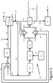
- FIG. 2 one embodiment of an ammonia plant 200 in accordance with the present invention is illustrated.
- ASU 213 produces oxygen containing stream 214.
- Hydrocarbon feedstock stream 201 is heated in feedstock preheater 243, thus producing heated feedstock stream 246.
- the heat for this preheating as indicated by heat exchange lines 244 and 245, may come from second heat exchanger 223, thus obtaining heat from shifted syngas stream 219.
- heat exchange lines 244 and 245 are thermally connected to heat exchange lines 224 and 225.
- Heated feedstock stream 246 is introduced into hydrogen desulfurization unit 202, thus producing desulfurized feed stream 203.
- Desulfurized feed stream 203 is combined with steam stream 204, thus generating ATR feed stream 205.
- ATR feed stream 205 is introduced into fired heater 206 thus producing preheated ATR feed stream 208, and flue gas stream 238.
- Heated ATR feed stream 208 is combined with purge gas recycle stream 236, thus forming combined ATR feed stream 209.
- Combined ATR feed stream 209 may then be introduced into optional pre-reformer 210, thereby optionally producing pre-reformed ATR feed stream 211.
- Combined ATR feed stream 209, or optional pre-reformed ATR feed stream 211 is then introduced into ATR 212 along with oxygen containing stream 214, thereby forming raw syngas stream 215.
- Raw syngas stream 215 is introduced into water-gas shift reactor 216, thereby producing shifted syngas stream 217.
- Shifted syngas stream 217 is divided into first stream 218 and second stream 219.
- First shifted gas stream 218 is then introduced into first heat exchanger 220, thereby producing first cooled shifted syngas stream 226.
- the cooling of stream 218 may take place by providing heat to the saturated steam stream 221 produced in the steam generating device located downstream ATR 212 and/or from steam generating device located downstream ammonia synthesis reactor 231 resulting in superheated steam stream 222.
- Second shifted gas stream 219 is then introduced into second heat exchanger 223 thereby producing second cooled shifted syngas stream 227.
- the cooling as indicated by heat exchange lines 224 and 225, may come from feedstock preheater 243, thus providing heat to hydrocarbon feedstock stream 201.
- heat exchange lines 224 and 225 are thermally connected to heat exchange lines 244 and 245.
- Second cooled shifted syngas stream 226 and second cooled shifted syngas stream 227 are combined, thus forming cooled shifted syngas stream 228. Cooled shifted syngas stream 228 is then introduced into CO2 capture unit and hydrogen separation device or synthesis gas preparation device 229.
- CO2 capture unit and hydrogen separation device or synthesis gas preparation device 229 produces hydrogen containing stream or ammonia synthesis gas stream 230 and purge gas stream 234.
- Nitrogen containing stream 240 may be added through mixing route alternative 1 to CO2 capture unit and synthesis gas preparation device 229 producing an ammonia synthesis gas stream 230/ 230a.
- CO2 capture unit and hydrogen separation device 229 may generate a hydrogen-rich stream (>90 mole% H2) 230 and then gets mixed with Nitrogen containing stream 240 through mixing route alternative 2 producing an ammonia synthesis gas stream 230a. Mixing of Nitrogen containing stream 240 in both scenarios results in a hydrogen to nitrogen molar ratio of 3:1 in the ammonia synthesis gas stream 230a.
- Ammonia synthesis gas stream 230a having hydrogen to nitrogen molar ratio of 3:1 is introduced into ammonia synthesis reactor 231, thereby producing raw ammonia stream 232.
- Purge gas fuel stream 234 is divided into purge gas fuel stream 235 and purge gas recycle stream 236.
- Purge gas fuel stream 235 is combined with hydrocarbon fuel stream 237 and introduced as fuel into fired heater 206.
- Second portion 236 is combined with preheated ATR feed stream 208 to produce combined ATR feed stream 209.
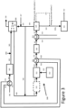
- ASU 313 produces oxygen containing stream 314.
- Hydrocarbon feedstock stream 301 is heated in feedstock preheater 343, thus producing heated feedstock stream 346.
- the heat for this preheating may come from various internal heat sources, as discussed in detail below.
- Heated feedstock stream 346 is introduced into hydrogen desulfurization unit 302, thus producing desulfurized feed stream 303.
- Desulfurized feed stream 303 is combined with steam stream 304, thus forming ATR feed stream 305.
- ATR feed stream 305 is introduced into fired heater 306 thus producing preheated ATR feed stream 308, and flue gas stream 338.
- Heated ATR feed stream 308 is combined with purge gas recycle stream 336, thus forming combined ATR feed stream 309.
- Combined ATR feed stream 309 may then be introduced into optional pre-reformer 310, thereby optionally producing pre-reformed ATR feed stream 311.
- Combined ATR feed stream 309, or optional pre-reformed ATR feed stream 311 is then introduced into ATR 312 along with oxygen containing stream 314, thereby forming raw syngas stream 315.
- Raw syngas stream 315 is then introduced into first heat exchanger 320, thereby producing further first cooled shifted syngas stream 326.
- the cooling for first heat exchanger 320 may come from various internal sources, as discussed in detail below.
- Further cooled raw syngas stream 326 is introduced into water-gas shift reactor 316, thereby producing shifted syngas stream 317.
- Shifted syngas stream 317 is introduced into second heat exchanger 323, thereby producing cooled shifted syngas stream 327.
- the cooling for second heat exchanger 323, may take place by providing heat to the saturated steam stream 324 produced in the steam generating device located downstream ATR 312 and/or from steam generating device located downstream ammonia synthesis reactor 331 resulting in superheated steam stream 325.
- Cooled shifted syngas stream 327 is then introduced into CO2 capture unit and hydrogen separation device or synthesis gas preparation device 329.
- CO2 capture unit and hydrogen separation device or synthesis gas preparation device 329 produces hydrogen-rich stream or ammonia synthesis gas stream 330 and purge gas stream 334.
- Nitrogen containing stream 340 may be added through mixing route alternative 1 to CO2 capture unit and synthesis gas preparation device 329 producing an ammonia synthesis gas stream 330/ 330a.
- CO2 capture unit and hydrogen separation device 329 may generate a hydrogen-rich stream (>90 mole% H2) 330 and then gets mixed with Nitrogen containing stream 340 through mixing route alternative 2 producing an ammonia synthesis gas stream 330a. Mixing of Nitrogen containing stream 340 in both scenarios results in a hydrogen to nitrogen molar ratio of 3:1 in the ammonia synthesis gas stream 330a.
- Ammonia synthesis gas stream 330a having hydrogen to nitrogen molar ratio of 3:1 is introduced into ammonia synthesis reactor 331, thereby producing raw ammonia stream 332.
- Purge gas fuel stream 334 is divided into purge gas fuel stream 335 and purge gas recycle stream 336.
- Purge gas fuel stream 335 is combined with hydrocarbon fuel stream 337 and introduced as fuel into fired heater 306.
- Second portion 336 is combined with preheated ATR feed stream 308 to produce combined ATR feed stream 309.
- ASU 313 produces oxygen containing stream 314.
- Hydrocarbon feedstock stream 301 is heated in feedstock preheater 343, thus producing heated feedstock stream 346.
- Heated feedstock stream 346 is introduced into hydrogen desulfurization unit 302, thus producing desulfurized feed stream 303.
- Desulfurized feed stream 303 is combined with steam stream 304, thus forming ATR feed stream 305.
- ATR feed stream 305 is introduced into fired heater 306 thus producing preheated ATR feed stream 308, and flue gas stream 338.
- Heated ATR feed stream 308 is combined with purge gas recycle stream 336, thus forming combined ATR feed stream 309.
- Combined ATR feed stream 309 may then be introduced into optional pre-reformer 310, thereby optionally producing pre-reformed ATR feed stream 311.
- Combined ATR feed stream 309, or optional pre-reformed ATR feed stream 311 is then introduced into ATR 312 along with oxygen containing stream 314, thereby forming raw syngas stream 315.
- Raw syngas stream 315 is then introduced into first heat exchanger 320, thereby producing further first cooled shifted syngas stream 326.
- the inventive solution allows a high intrinsic CO 2 capture rate in decarbonized ammonia production units with an overall low carbon intensity based on autothermal reforming which principally is targeted to achieve by reduction of heating demand from fired heater/ heat of combustion.
- the inventive solution comprises:
- the inventive solution also comprises:
- the essential step is to produce a low carbon hydrogen-rich stream (>90 mole% H2) or low carbon ammonia syngas with hydrogen to nitrogen molar ratio of 3:1.
- a low carbon hydrogen-rich stream >90 mole% H2
- low carbon ammonia syngas with hydrogen to nitrogen molar ratio of 3:1.
- all the embodiments cited may be used to produce low carbon hydrogen-rich stream (>90 mole% H2) only and utilize that hydrogen-rich stream for different usage other than ammonia production.
Landscapes
- Chemical & Material Sciences (AREA)
- Organic Chemistry (AREA)
- Chemical Kinetics & Catalysis (AREA)
- Inorganic Chemistry (AREA)
- Engineering & Computer Science (AREA)
- Combustion & Propulsion (AREA)
- Health & Medical Sciences (AREA)
- General Health & Medical Sciences (AREA)
- Analytical Chemistry (AREA)
- Hydrogen, Water And Hydrids (AREA)
Abstract
Process and method to produce ammonia with high CO<sub>2</sub> capture rate. The invention entails production of ammonia in an efficient and innovative way with minimum carbon emissions within the production unit by use of only one CO<sub>2</sub> removal unit and a minimum process heat exchange duties provided by heat of combustion. The proposed novel solution allows achieving a direct CO<sub>2</sub> capture rate of >95% by the autothermal reforming based ammonia production process with one CO<sub>2</sub> removal unit with an efficient thermal integration and a low duty fired heater ensuring minimum direct carbon emission.
Description
- This application claims the benefit of priority under 35 U.S.C. § 119 (a) and (b) to
US Provisional Patent Application No. 63/469,839, filed May 31, 2023 - Ammonia production is currently associated with substantial CO2 emissions as the syngas for ammonia production is generated by reforming at multiple steps - one primary reforming step which takes place in a classical tubular steam methane reformer with a combustion furnace; followed by a secondary reforming step which takes place in a catalytic reactor vessel. In this reactor vessel, air (which contains N2 molecules) is introduced which helps in partial combustion of hydrocarbon molecules coming from the primary reforming step before the gas enters the catalyst layer of the reactor vessel. When the gas enters the catalyst layer, the secondary reforming takes place enhancing the conversion of hydrocarbon to CO and H2. As the combustion furnace is inevitable with the conventional tubular steam methane reformer, a considerable amount of flue gas is emitted through the furnace exit which contains a considerable amount of CO2 and thus makes the whole process significantly CO2-intensive.
- Classical ammonia plant configurations intrinsically include one CO2 capture step before final conditioning of ammonia synthesis gas in order to protect the ammonia synthesis catalyst. This step can be considered as a "pre-combustion CO2 capture step" as the "capturable CO2" is generated only from reforming and shift reaction and not by combustion. Pre-combustion CO2 capture can achieve an overall CO2 capture of ~ 50-60% with conventional tubular steam methane reforming (SMR) based syngas generation process.
- However, with this configuration, the overall direct CO2 capture rate is poor as a significant amount of CO2 gets emitted via flue gas. To increase the overall capture rate, there are only two options as follows:
- Post-combustion capture of CO2: A unit for capturing CO2 emitted via flue gas (absorption and/or cryogenic) and by that, overall carbon capture rate can be enhanced and emission can be reduced. However, capture of CO2 from flue gas is less efficient attributing to its availability at lower concentration (hence lower partial pressure) resulting in higher operational cost and capital investments in combination with significantly higher plot area requirement.
- Additional production of H2-rich synthesis gas: Alternatively, to avoid the flue gas CO2 capture unit, additional H2-rich syngas can be produced via reforming and shift and then routing the surplus H2 (via H2-rich gas) to the combustion furnace of the tubular steam reformer. Firing of H2-rich gas reduces CO2 emission through the furnace. However, this means processing of additional feedstock and higher material flow through the gas production unit, thereby increasing the operational cost and capital investments significantly.
- To avoid the inefficiency and cost penalty caused by either of the abovementioned two approaches, ammonia production can include only one autothermal reforming step instead of primary and secondary reforming steps (as described earlier). Instead of a big combustion furnace associated with a tubular reformer and high flow of flue gas, the Autothermal process is normally associated with a fired heater with much lower process heat duty requirements compared to SMR furnace and therefore resulting in much less flue gas flow and emissions. That is why, in an Autothermal reforming based process for generation of ammonia synthesis gas, intrinsic CO2 capture of 85-90% is achieved from produced syngas.
- Main thermal duty exchanges in the fired heater in an autothermal reforming based ammonia synthesis gas generation configuration, correspond to some process heat exchange which may include preheating of gas entering the feedstock purification section (e.g. hydrogenation and/or desulfurization section) and/or preheating of gas entering different steps of reforming (e.g. pre-reformer or autothermal reformer reactor) and/or superheating of steam produced in the process. All these process thermal duty demands govern the firing required in the fired heater and thus govern the extent of CO2 emissions. This CO2 emission results in the intrinsic CO2 capture rate of 85-90%. The CO2 capture rate can be increased by firing a split stream of product H2 in the fired heater as fuel. This method reduces the hydrocarbon fuel consumption and thereby reduces the carbon emission through the fired heater leading to a direct carbon capture rate >95%.
- However, to generate this additional H2 to be used as fuel, more hydrocarbon feed needs to be reformed and the carbon footprint of the process is increased by that resulting in higher Scope 3 emissions. Also, to reform more hydrocarbon feedstock, more oxygen intake is also required, which means higher power consumption by the Air Separation Unit. Hence, enhancing the CO2 capture is realized by increasing the Scope 2 (electricity import) and Scope 3 (hydrocarbon feedstock) emissions which is counterproductive in terms of overall emissions. Or in other words, direct emissions are minimized by increasing indirect emissions.
- In one embodiment of the current invention, the proposed novel solution allows achieving a direct CO2 capture rate of >95% by the autothermal reforming based ammonia production process with one CO2 removal unit with an efficient thermal integration and a low duty fired heater ensuring minimum direct carbon emission.
- Process and method to produce ammonia with high CO2 capture rate. The invention entails production of ammonia in an efficient and innovative way with minimum carbon emissions within the production unit by use of only one CO2 removal unit and a minimum process heat exchange duties provided by heat of combustion. The proposed novel solution allows achieving a direct CO2 capture rate of >95% by the autothermal reforming based ammonia production process with one CO2 removal unit with an efficient thermal integration and a low duty fired heater ensuring minimum direct carbon emission.
- For a further understanding of the nature and objects for the present invention, reference should be made to the following detailed description, taken in conjunction with the accompanying drawings, in which like elements are given the same or analogous reference numbers and wherein:
-
Figure 1 is a schematic representation of a basic state-of-the-art ammonia plant utilizing autothermal reformer, as is known in the art. -
Figure 2 is a schematic representation of one embodiment of an ammonia plant, in accordance with the present invention. -
Figure 3 is a schematic representation of another embodiment of an ammonia plant, in accordance with the present invention. -
Figure 4 is a schematic representation of another embodiment of an ammonia plant, in accordance with the present invention. -
- 100 = ammonia plant as known in the art
- 101 = hydrocarbon feedstock stream
- 102 = fired heater
- 103 = heat exchange coils
- 104 = heated feedstock stream
- 105 = hydrogen desulfurization unit
- 106 = desulfurized feed stream
- 107 = steam stream
- 108 = ATR feed stream
- 109 = heated ATR feed stream
- 110 = combined ATR feed stream
- 111 = (optional) pre-reformer
- 112 = combined (optionally pre-reformed) ATR feed stream
- 113 = ATR
- 114 = ASU
- 115 = oxygen containing stream
- 116 = raw syngas stream
- 117 = water-gas shift converter
- 118 = shifted syngas stream
- 119 = hydrogen separation device
- 120 = ammonia synthesis stream
- 121 = ammonia synthesis reactor
- 122 = raw ammonia stream
- 123 = purge gas stream
- 124 = purge gas fuel stream
- 125 = purge gas recycle stream
- 126 = hydrocarbon fuel stream
- 127 = flue gas stream
- 200 = ammonia plant according to the present invention
- 201 = hydrocarbon feedstock stream
- 202 = hydrogen desulfurization unit
- 203 = desulfurized feed stream
- 204 = steam stream
- 205 = ATR feed stream
- 206 = fired heater
- 207 = heat exchange coils
- 208 = heated ATR feed stream
- 209 = combined ATR feed stream
- 210 = (optional) pre-reformer
- 211 = combined (optionally pre-reformed) ATR feed stream
- 212 = ATR
- 213 = ASU
- 214 = oxygen containing stream
- 215 = raw syngas stream
- 216 = water-gas shift converter
- 217 = shifted syngas stream
- 218 = first shifted syngas stream
- 219 = second shifted syngas stream
- 220 = first heat exchanger
- 221 = saturated steam stream
- 222 = superheated steam stream
- 223 = second heat exchanger
- 224 = heat transfer line for second heat exchanger
- 225 = heat transfer line for second heat exchanger
- 226 = first cooled shifted syngas stream
- 227 = second cooled shifted syngas stream
- 228 = cooled shifted syngas stream
- 229 = CO2 Capture unit+hydrogen separation/ synthesis gas preparation device
- 230 = hydrogen rich stream/ ammonia synthesis stream
- 230a = ammonia synthesis stream
- 231 = ammonia synthesis reactor
- 232 = raw ammonia stream
- 234 = purge gas stream
- 235 = purge gas fuel stream
- 236 = purge gas recycle stream
- 237 = hydrocarbon fuel stream
- 238 = flue gas stream
- 240 = nitrogen containing stream
- 243 = feed preheater
- 244 = heat transfer line for feed preheater
- 245 = heat transfer line for feed preheater
- 300 = ammonia plant according to the present invention
- 301 = hydrocarbon feedstock stream
- 302 = hydrogen desulfurization unit
- 303 = desulfurized feed stream
- 304 = steam stream
- 305 = ATR feed stream
- 306 = fired heater
- 307 = heat exchange coils
- 308 = heated ATR feed stream
- 309 = combined ATR feed stream
- 310 = (optional) pre-reformer
- 311 = combined (optionally pre-reformed) ATR feed stream
- 312 = ATR
- 313 = ASU
- 314 = oxygen containing stream
- 315 = raw syngas stream
- 316 = water-gas shift converter
- 317 = shifted syngas stream
- 320 = first heat exchanger
- 321 = heat transfer line for first heat exchanger/ saturated steam stream
- 322 = heat transfer line for first heat exchanger/ superheated steam stream
- 323 = second heat exchanger
- 324 = heat transfer line for second heat exchanger/ saturated steam stream
- 325 = heat transfer line for second heat exchanger/ superheated steam stream
- 326 = first cooled shifted syngas stream
- 327 = second cooled shifted syngas stream
- 329 = CO2 Capture unit+hydrogen separation/ synthesis gas preparation device
- 330 = hydrogen rich stream/ ammonia synthesis stream
- 330a = ammonia synthesis stream
- 331 = ammonia synthesis reactor
- 332 = raw ammonia stream
- 334 = purge gas stream
- 335 = purge gas fuel stream
- 336 = purge gas recycle stream
- 337 = hydrocarbon fuel stream
- 338 = flue gas stream
- 340 = nitrogen containing stream
- 343 = feed preheater
- 344 = heat transfer line for feed preheater
- 345 = heat transfer line for feed preheater
- 346 = heated feedstock stream
- Illustrative embodiments of the invention are described below. While the invention is susceptible to various modifications and alternative forms, specific embodiments thereof have been shown by way of example in the drawings and are herein described in detail. It should be understood, however, that the description herein of specific embodiments is not intended to limit the invention to the particular forms disclosed, but on the contrary, the intention is to cover all modifications, equivalents, and alternatives falling within the spirit and scope of the invention as defined by the appended claims.
- It will of course be appreciated that in the development of any such actual embodiment, numerous implementation-specific decisions must be made to achieve the developer's specific goals, such as compliance with system-related and business-related constraints, which will vary from one implementation to another. Moreover, it will be appreciated that such a development effort might be complex and time-consuming, but would nevertheless be a routine undertaking for those of ordinary skill in the art having the benefit of this disclosure.
- In one embodiment of the present invention, a method of producing low carbon ammonia is described wherein the direct carbon emissions are minimized without increasing any Scope 3 emissions and with a minimized impact on
Scope 2 emissions, thus reducing the carbon intensity of the process. - Turning to
Figure 1 , a basic state-of-the-art ammonia plant 100 utilizingautothermal reformer 113 is illustrated.ASU 114 producesoxygen containing stream 115.Hydrocarbon feedstock stream 101 is introduced into firedheater 102 wherein it is preheated in heat exchange coils 103, thus producingpreheated feedstock stream 104 andflue gas stream 127.Preheated feedstock stream 104 is introduced intohydrogen desulfurization unit 105, thus producing desulfurizedfeed stream 106.Desulfurized feed stream 106 is combined withsteam stream 107, thus formingATR feed stream 108.ATR feed stream 108 is introduced into firedheater 102 thus producing preheatedATR feed stream 109.Saturated steam stream 128 is also introduced into firedheater 102, thus producingsuperheated steam stream 129.Saturated steam stream 128 may come from steam generating device locateddownstream ATR 113 and/or from steam generating device located downstreamammonia synthesis reactor 121. - Preheated
ATR feed stream 109 is combined with purgegas recycle stream 125, thereby forming combinedATR feed stream 110. CombinedATR feed stream 110 may then be introduced intooptional pre-reformer 111, thereby optionally producing pre-reformedATR feed stream 112. CombinedATR feed stream 110, or optional pre-reformedATR feed stream 112, is then introduced intoATR 113 along withoxygen containing stream 115, thereby formingraw syngas stream 116.Raw syngas stream 116 is then introduced into water-gas shift reactor 117, thereby producing shiftedsyngas stream 118. Shiftedsyngas stream 118 is then introduced intohydrogen separation device 119.Hydrogen separation device 119 produces ammoniasynthesis gas stream 120 and purgegas stream 123. - Ammonia
synthesis gas stream 120 is introduced intoammonia synthesis reactor 121, thereby producingraw ammonia stream 122.Purge gas stream 123 is divided into purgegas fuel stream 124 and purgegas recycle stream 125. Purgegas fuel stream 123 is combined withhydrocarbon fuel stream 126 and introduced as fuel into firedheater 102.Second portion 125 is combined with preheatedATR feed stream 109 to produce combinedATR feed stream 110. - State of the art autothermal reforming technologies are associated with at least one fired heater including heat exchange coils providing sufficient process heat. The temperature required for the different process steps of the production unit is provided by these heat exchanges. The heat duty required for this heat exchange is provided by firing of hydrocarbon fuel that leads to CO2 emissions. Main thermal duty exchanges in the fired heater in an autothermal reforming based ammonia synthesis gas generation configuration, correspond to some process heat exchange which may include preheating of gas entering the feedstock purification section (e.g. hydrogenation and/or desulfurization section) and/or preheating of gas entering different steps of reforming (e.g. pre-reformer or autothermal reformer reactor) and superheating of steam produced in the process. All these process thermal duty demands govern the firing required in the fired heater and thus govern the extent of CO2 emissions. The more heat exchange happens in the fired heater, heat duty requirement by fuel increases, and so increases the CO2 emissions.
- This CO2 emission results in the intrinsic CO2 capture rate of 85-90%. The CO2 capture rate can be increased by producing more hydrogen than required as product by additional feedstock processing (reforming, shift, CO2 removal, gas conditioning) and firing that additional H2 product in the fired heater. This method reduces the hydrocarbon fuel consumption and thereby reduces the carbon emission through the fired heater leading to a direct carbon capture rate >95%.
- However, to generate this additional H2 to be used as fuel, more hydrocarbon feed needs to be reformed and the carbon footprint of the process is increased by that resulting in higher scope 3 emissions. Also, to reform more hydrocarbon feedstock, more oxygen intake is also required, which means higher power consumption by the Air Separation Unit. Hence, enhancing the CO2 capture is realized by increasing the Scope 2 (electricity import) and Scope 3 (hydrocarbon feedstock) emissions which is counterproductive in terms of overall emissions. Or in other words, direct emissions are minimized by increasing indirect emissions. Thus, additional processing of feedstock has a direct adverse impact on carbon intensity as well as both operating and capital cost. Additional feedstock consumption, therefore higher oxygen, power and other utility consumption increases the operating cost. On the other hand, due to higher effective material flow, all equipment gets oversized and therefore the capital investment goes higher.
- The present invention describes a method of producing low carbon ammonia by autothermal reforming process where the direct carbon emissions are minimized without increasing any scope 3 emissions and with a minimized impact on
scope 2 emissions, thus reducing the overall carbon intensity of the ammonia production process. - Turning to
Figure 2 , one embodiment of anammonia plant 200 in accordance with the present invention is illustrated.ASU 213 producesoxygen containing stream 214.Hydrocarbon feedstock stream 201 is heated infeedstock preheater 243, thus producingheated feedstock stream 246. The heat for this preheating, as indicated byheat exchange lines second heat exchanger 223, thus obtaining heat from shiftedsyngas stream 219. In this arrangement,heat exchange lines exchange lines -
Heated feedstock stream 246 is introduced intohydrogen desulfurization unit 202, thus producing desulfurizedfeed stream 203.Desulfurized feed stream 203 is combined withsteam stream 204, thus generatingATR feed stream 205.ATR feed stream 205 is introduced into firedheater 206 thus producing preheatedATR feed stream 208, andflue gas stream 238. HeatedATR feed stream 208 is combined with purgegas recycle stream 236, thus forming combinedATR feed stream 209. CombinedATR feed stream 209 may then be introduced intooptional pre-reformer 210, thereby optionally producing pre-reformed ATR feed stream 211. CombinedATR feed stream 209, or optional pre-reformed ATR feed stream 211, is then introduced intoATR 212 along withoxygen containing stream 214, thereby formingraw syngas stream 215. -
Raw syngas stream 215 is introduced into water-gas shift reactor 216, thereby producing shiftedsyngas stream 217. Shiftedsyngas stream 217 is divided intofirst stream 218 andsecond stream 219. First shiftedgas stream 218 is then introduced intofirst heat exchanger 220, thereby producing first cooled shiftedsyngas stream 226. The cooling ofstream 218 may take place by providing heat to the saturatedsteam stream 221 produced in the steam generating device locateddownstream ATR 212 and/or from steam generating device located downstreamammonia synthesis reactor 231 resulting insuperheated steam stream 222. - Second shifted
gas stream 219 is then introduced intosecond heat exchanger 223 thereby producing second cooled shiftedsyngas stream 227. The cooling, as indicated byheat exchange lines feedstock preheater 243, thus providing heat tohydrocarbon feedstock stream 201. In this arrangement,heat exchange lines exchange lines - First cooled shifted
syngas stream 226 and second cooled shiftedsyngas stream 227 are combined, thus forming cooled shiftedsyngas stream 228. Cooled shiftedsyngas stream 228 is then introduced into CO2 capture unit and hydrogen separation device or synthesisgas preparation device 229. CO2 capture unit and hydrogen separation device or synthesisgas preparation device 229 produces hydrogen containing stream or ammoniasynthesis gas stream 230 and purgegas stream 234.Nitrogen containing stream 240 may be added through mixingroute alternative 1 to CO2 capture unit and synthesisgas preparation device 229 producing an ammoniasynthesis gas stream 230/ 230a. - Alternatively, CO2 capture unit and
hydrogen separation device 229 may generate a hydrogen-rich stream (>90 mole% H2) 230 and then gets mixed withNitrogen containing stream 240 through mixingroute alternative 2 producing an ammoniasynthesis gas stream 230a. Mixing ofNitrogen containing stream 240 in both scenarios results in a hydrogen to nitrogen molar ratio of 3:1 in the ammoniasynthesis gas stream 230a. - Ammonia
synthesis gas stream 230a having hydrogen to nitrogen molar ratio of 3:1 is introduced intoammonia synthesis reactor 231, thereby producingraw ammonia stream 232. - Purge
gas fuel stream 234 is divided into purgegas fuel stream 235 and purgegas recycle stream 236. Purgegas fuel stream 235 is combined withhydrocarbon fuel stream 237 and introduced as fuel into firedheater 206.Second portion 236 is combined with preheatedATR feed stream 208 to produce combinedATR feed stream 209. - . Turning first to
Figure 3 ,ASU 313 producesoxygen containing stream 314.Hydrocarbon feedstock stream 301 is heated infeedstock preheater 343, thus producingheated feedstock stream 346. The heat for this preheating, as indicated byheat transfer lines -
Heated feedstock stream 346 is introduced intohydrogen desulfurization unit 302, thus producing desulfurizedfeed stream 303.Desulfurized feed stream 303 is combined withsteam stream 304, thus formingATR feed stream 305.ATR feed stream 305 is introduced into firedheater 306 thus producing preheatedATR feed stream 308, andflue gas stream 338. HeatedATR feed stream 308 is combined with purgegas recycle stream 336, thus forming combinedATR feed stream 309. CombinedATR feed stream 309 may then be introduced intooptional pre-reformer 310, thereby optionally producing pre-reformedATR feed stream 311. CombinedATR feed stream 309, or optional pre-reformedATR feed stream 311, is then introduced intoATR 312 along withoxygen containing stream 314, thereby formingraw syngas stream 315. -
Raw syngas stream 315 is then introduced intofirst heat exchanger 320, thereby producing further first cooled shiftedsyngas stream 326. The cooling forfirst heat exchanger 320, as indicated byheat transfer lines raw syngas stream 326 is introduced into water-gas shift reactor 316, thereby producing shiftedsyngas stream 317. Shiftedsyngas stream 317 is introduced intosecond heat exchanger 323, thereby producing cooled shiftedsyngas stream 327. The cooling forsecond heat exchanger 323, may take place by providing heat to the saturatedsteam stream 324 produced in the steam generating device locateddownstream ATR 312 and/or from steam generating device located downstreamammonia synthesis reactor 331 resulting insuperheated steam stream 325. - Cooled shifted
syngas stream 327 is then introduced into CO2 capture unit and hydrogen separation device or synthesisgas preparation device 329. CO2 capture unit and hydrogen separation device or synthesisgas preparation device 329 produces hydrogen-rich stream or ammoniasynthesis gas stream 330 and purgegas stream 334.Nitrogen containing stream 340 may be added through mixingroute alternative 1 to CO2 capture unit and synthesisgas preparation device 329 producing an ammoniasynthesis gas stream 330/ 330a. - Alternatively, CO2 capture unit and
hydrogen separation device 329 may generate a hydrogen-rich stream (>90 mole% H2) 330 and then gets mixed withNitrogen containing stream 340 through mixingroute alternative 2 producing an ammoniasynthesis gas stream 330a. Mixing ofNitrogen containing stream 340 in both scenarios results in a hydrogen to nitrogen molar ratio of 3:1 in the ammoniasynthesis gas stream 330a. - Ammonia
synthesis gas stream 330a having hydrogen to nitrogen molar ratio of 3:1 is introduced intoammonia synthesis reactor 331, thereby producingraw ammonia stream 332. - Purge
gas fuel stream 334 is divided into purgegas fuel stream 335 and purgegas recycle stream 336. Purgegas fuel stream 335 is combined withhydrocarbon fuel stream 337 and introduced as fuel into firedheater 306.Second portion 336 is combined with preheatedATR feed stream 308 to produce combinedATR feed stream 309. - Turning
Figures 3 and4 ,ASU 313 producesoxygen containing stream 314.Hydrocarbon feedstock stream 301 is heated infeedstock preheater 343, thus producingheated feedstock stream 346. -
Feedstock preheater 343 may exchange heat withfirst heat exchanger 320, thus obtaining heat fromraw syngas stream 315 resulting in cooledraw syngas stream 326. In this arrangement,heat exchange lines exchange lines 321 and 322 (as illustrated inFigure 3 ), -
Feedstock preheater 343 may exchange heat withsecond heat exchanger 323, thus obtaining heat from shiftedsyngas stream 317 resulting in cooledraw syngas stream 327. In this arrangement,heat exchange lines exchange lines 324 and 325 (as illustrated inFigure 4 ). -
Heated feedstock stream 346 is introduced intohydrogen desulfurization unit 302, thus producing desulfurizedfeed stream 303.Desulfurized feed stream 303 is combined withsteam stream 304, thus formingATR feed stream 305.ATR feed stream 305 is introduced into firedheater 306 thus producing preheatedATR feed stream 308, andflue gas stream 338. HeatedATR feed stream 308 is combined with purgegas recycle stream 336, thus forming combinedATR feed stream 309. CombinedATR feed stream 309 may then be introduced intooptional pre-reformer 310, thereby optionally producing pre-reformedATR feed stream 311. CombinedATR feed stream 309, or optional pre-reformedATR feed stream 311, is then introduced intoATR 312 along withoxygen containing stream 314, thereby formingraw syngas stream 315. -
Raw syngas stream 315 is then introduced intofirst heat exchanger 320, thereby producing further first cooled shiftedsyngas stream 326. -
First heat exchanger 320 may provide heat tofeedstock preheater 343, thus providing heathydrocarbon feedstock stream 301. In this arrangement,heat exchange lines exchange lines Figure 3 ) -
First heat exchanger 320 may provide heat to the saturatedsteam stream 321 produced in the steam generating device locateddownstream ATR 312 and/or from steam generating device located downstreamammonia synthesis reactor 331 resulting in superheated steam stream 322 (as illustrated inFigure 4 ). - Further cooled
raw syngas stream 326 is introduced into water-gas shift reactor 316, thereby producing shiftedsyngas stream 317. Shiftedsyngas stream 317 is introduced intosecond heat exchanger 323, thereby producing cooled shiftedsyngas stream 327. -
Second heat exchanger 323 may provide heat to the saturatedsteam stream 324 produced in the steam generating device locateddownstream ATR 312 and/or from steam generating device located downstreamammonia synthesis reactor 331 resulting in superheated steam stream 325 (as illustrated inFigure 3 ). -
Second heat exchanger 323 may provide heat tofeedstock preheater 343, thus providing heathydrocarbon feedstock stream 301. In this arrangement,heat exchange lines exchange lines 344 and 345 (as illustrated inFigure 4 ). - The inventive solution allows a high intrinsic CO2 capture rate in decarbonized ammonia production units with an overall low carbon intensity based on autothermal reforming which principally is targeted to achieve by reduction of heating demand from fired heater/ heat of combustion.
- The inventive solution comprises:
- employing an efficient synthesis gas generation process for ammonia production that may consist of at least an oxygen based catalytic autothermal reforming step, at least one water-gas shift reaction step with at least one catalytic reactor and employing a CO2 capture unit and a gas purification or gas conditioning unit,
- the efficient syngas generation process is characterized in such a way that there is a minimum requirement of process/ by-product/ utility heating by heat of combustion or electrical heat,
- The above characterization is configured by superheating the produced steam by heat recovery of the process gas in the syngas generation section, thereby eliminating the requirement of superheating the steam in the fired heater using heat of combustion of hydrocarbon fuel.
- The inventive solution also comprises:
- ammonia production based on pure oxygen-based catalytic autothermal reforming of hydrocarbon feedstock. In the autothermal reforming process, most of the hydrocarbon gets converted to CO and H2. Before catalytic interaction, in the autothermal reactor, partial combustion of hydrocarbon takes place which is an exothermic reaction. High temperature originating from the exothermic reaction facilitates the catalytic reforming reaction which is endothermic in nature. Consequently, the reformed gas exits the autothermal reactor at high temperature. Downstream autothermal reforming, a water-gas shift section converts CO to CO2 in presence of water. The water is added in the form of saturated or superheated steam upstream autothermal reforming and/or upstream water-gas shift. Downstream shift, CO2 is removed by physical and/or chemical absorption of CO2 and/or Cryogenic separation of CO2. After CO2 removal, the process gas contains mainly H2. Based on the CO2 removal process, H2-rich process gas may contain impurities like unconverted CH4, unconverted CO and traces of Ar. A gas purification/ conditioning step is required in order to remove the impurities resulting in a pure H2 stream or a mixture of pure H2 and N2 stream in the ratio of 3:1. This ratio is the stoichiometric number required for ammonia synthesis in the ammonia synthesis loop. Purge gas, as produced in the CO2 removal section and/or gas purification/ conditioning step, rich in impurities, is routed to the fired heater and/or recycled back to the reforming process to minimize the loss of carbon atom.
- Process heat downstream autothermal reformer as well as downstream water-gas shift can be recovered efficiently by steam generation and/or preheating of feedstock and/or superheating of steam.
- By superheating the steam utilizing process heat eliminates the requirement of superheating the steam in the fired heater using heat of combustion.
- As the steam superheating is avoided by the heat of combustion, the process heat duty demand in the fired heater gets significantly reduced. This leads to significant reduction in the hydrocarbon fuel consumption for the fired heater and consequently results in negligible emission and considerably high direct CO2 capture rate.
- Superheated steam is also generated from the ammonia synthesis loop by means of the heat recovery attributing to the exothermic ammonia synthesis reaction.
- Co-produced superheated steam from heat recovery of synthesis gas generation section (ATR+Shift) and of ammonia synthesis loop can be used to drive different compressors of the plant and/or to generate electricity and/or for exporting outside the plant.
- With these inventive steps, it is possible to achieve a very high direct CO2 capture rate without compromising the indirect capture rate, especially Scope 3 capture rate attributing to hydrocarbon feedstock consumption. As the steam superheating is executed utilizing the process heat and not by the heat of combustion, hydrocarbon fuel demand and hence carbon footprint of the plant gets significantly reduced. Apart from higher capture rate, cost of operation as well as capital investment gets minimized.
- This solution distinguishes itself from others for the following reasons:
- Achieving very high CO2 capture rate (>95-99%) without having any need of H2 firing.
- No H2 firing need means no additional feedstock processing and thereby no additional utility consumption, hence a minimized operating cost.
- No H2 firing need also means the plant shall produce according to the product requirement and hence no oversizing leading minimized capital investment.
- It is to be noted that to produce low carbon ammonia, the essential step is to produce a low carbon hydrogen-rich stream (>90 mole% H2) or low carbon ammonia syngas with hydrogen to nitrogen molar ratio of 3:1. Hence, all the embodiments cited may be used to produce low carbon hydrogen-rich stream (>90 mole% H2) only and utilize that hydrogen-rich stream for different usage other than ammonia production.
- It will be understood that many additional changes in the details, materials, steps and arrangement of parts, which have been herein described in order to explain the nature of the invention, may be made by those skilled in the art within the principle and scope of the invention as expressed in the appended claims. Thus, the present invention is not intended to be limited to the specific embodiments in the examples given above.
Claims (18)
- A process for producing hydrogen-rich gas and/or ammonia synthesis gas to produce ammonia, comprising:• producing a raw syngas stream within an autothermal reformer from an ATR feed stream comprising a hydrocarbon feed stream and a steam stream, wherein the raw syngas stream comprises hydrogen, carbon monoxide, carbon dioxide, and water,• cooling the raw syngas stream by vaporizing boiler feed water thereby producing a steam stream and a second syngas stream,• the second syngas stream is mixed with water and/or steam added prior to introduction to a catalytic water-gas shift reactor thereby producing a minimum required ratio of steam to dry gas for the shift catalyst (> 0.2 mol/mol),• producing a first shifted syngas stream by shift reaction inside the catalytic water-gas shift reactor,• producing a second shifted syngas stream by cooling the first shifted syngas stream by heat exchange with a steam stream superheater or a hydrocarbon feed stream or a mixed stream of hydrocarbon and steam or by raising steam or all of these,• further cooling the second shifted syngas stream in subsequent step(s) prior to introduction to pre-combustion carbon dioxide capture unit producing at least one carbon dioxide -rich stream and one carbon dioxide-depleted stream, and• preheating either a process stream or superheating a steam stream or both, with a supplementary fired heater,wherein:at least a portion of the hydrogen-rich stream and/or the ammonia synthesis gas stream is used for ammonia synthesis,the sum of the heat exchange duties taking place in the fired heater does not exceed 1 MWh/ ton ammonia (on 100% ammonia purity basis) produced or 3MWh/ton hydrogen (on 100% hydrogen purity basis) produced andthe direct carbon dioxide emission from the ammonia production process does not exceed 0.7 kg carbon dioxide/ kg ammonia (on 100% ammonia purity basis) produced or 2.5 kg carbon dioxide / kg hydrogen (on 100% hydrogen purity basis) produced.
- The process of claim 1, wherein at least a portion of the hydrogen-rich stream is used for any usage other than ammonia synthesis.
- The process of claim 1, wherein the pre-combustion carbon dioxide capture unit is preceded or succeeded by a hydrogen purification unit producing at least one hydrogen-rich stream (>90 mole% hydrogen purity).
- The process of claim 3, wherein an external nitrogen-containing stream is added to at least a portion of the hydrogen-rich stream (>90 mole% hydrogen purity) to produce at least an ammonia synthesis gas stream having a hydrogen to nitrogen molar ration of 3:1.
- The process of claim 1, wherein the ATR feed stream passes through a prereforming stage.
- The process of claim 1, wherein the fired heater is replaced and/or supplemented by an electric heater.
- A process for producing hydrogen-rich gas and/or ammonia synthesis gas to produce ammonia, comprising:• producing a raw syngas stream within an autothermal reformer from an ATR feed stream comprising a hydrocarbon feed stream and a steam stream, wherein the raw syngas stream comprises hydrogen, carbon monoxide, carbon dioxide, and water,• cooling the raw syngas stream by vaporizing boiler feed water thereby producing a steam stream and a second syngas stream,• superheating a steam stream by utilizing the sensible heat of the second syngas stream, thereby producing a third syngas stream,• the third syngas stream is mixed with water and/or steam added prior to introduction to a catalytic water-gas shift reactor thereby producing a minimum required ratio of steam to dry gas for the shift catalyst (> 0.2 mol/mol),• producing a first shifted syngas stream by shift reaction inside the catalytic water-gas shift reactor,• producing a second shifted syngas stream by cooling the first shifted syngas stream by heat exchange with a hydrocarbon feed stream or a mixed stream of hydrocarbon and steam or by raising steam or all of these,• further cooling the second shifted syngas stream in subsequent step(s) prior to introduction to pre-combustion carbon dioxide capture unit producing at least one carbon dioxide -rich stream and one carbon dioxide-depleted stream, and• preheating either a process stream or superheating a steam stream or both, with a supplementary fired heater,wherein:at least a portion of the hydrogen-rich stream and/or the ammonia synthesis gas stream is used for ammonia synthesis,the sum of the heat exchange duties taking place in the fired heater does not exceed 1 MWh/ ton ammonia (on 100% ammonia purity basis) produced or 3MWh/ton hydrogen (on 100% hydrogen purity basis) produced andthe direct carbon dioxide emission from the ammonia production process does not exceed 0.7 kg carbon dioxide/ kg ammonia (on 100% ammonia purity basis) produced or 2.5 kg carbon dioxide / kg hydrogen (on 100% hydrogen purity basis) produced.
- The process of claim 7, wherein at least a portion of the hydrogen-rich stream is used for any usage other than ammonia synthesis.
- The process of claim 7, wherein the pre-combustion carbon dioxide capture unit is preceded or succeeded by a hydrogen purification unit producing at least one hydrogen-rich stream (>90 mole% hydrogen purity).
- The process of claim 9, wherein an external nitrogen-containing stream is added to at least a portion of the hydrogen-rich stream (>90 mole% hydrogen purity) to produce at least an ammonia synthesis gas stream having a hydrogen to nitrogen molar ration of 3:1.
- The process of claim 7, wherein the ATR feed stream passes through a prereforming stage.
- The process of claim 7, wherein the fired heater is replaced and/or supplemented by an electric heater.
- A process for producing hydrogen-rich gas and/or ammonia synthesis gas to produce ammonia, comprising:• producing a raw syngas stream within an autothermal reformer from an ATR feed stream comprising a hydrocarbon feed stream and a steam stream, wherein the raw syngas stream comprises hydrogen, carbon monoxide, carbon dioxide, and water,• cooling the raw syngas stream by vaporizing boiler feed water thereby producing a steam stream and a second syngas stream,• heating a hydrocarbon feed stream by using the sensible heat of the second syngas stream, thereby producing a third syngas stream,• the third syngas stream is mixed with water and/or steam added prior to introduction to a catalytic water-gas shift reactor thereby producing a minimum required ratio of steam to dry gas for the shift catalyst (> 0.2 mol/mol),• producing a first shifted syngas stream by shift reaction inside the catalytic water-gas shift reactor,• producing a second shifted syngas stream by cooling the first shifted syngas stream by heat exchange with a steam stream superheater or a hydrocarbon feed stream or a mixed stream of hydrocarbon and steam or by raising steam or all of these,• further cooling the second shifted syngas stream in subsequent step(s) prior to introduction to pre-combustion carbon dioxide capture unit producing at least one carbon dioxide -rich stream and one carbon dioxide-depleted stream, and• preheating either a process stream or superheating a steam stream or both, with a supplementary fired heater,wherein:at least a portion of the hydrogen-rich stream and/or the ammonia synthesis gas stream is used for ammonia synthesis,the sum of the heat exchange duties taking place in the fired heater does not exceed 1 MWh/ ton ammonia (on 100% ammonia purity basis) produced or 3MWh/ton hydrogen (on 100% hydrogen purity basis) produced andthe direct carbon dioxide emission from the ammonia production process does not exceed 0.7 kg carbon dioxide/ kg ammonia (on 100% ammonia purity basis) produced or 2.5 kg carbon dioxide / kg hydrogen (on 100% hydrogen purity basis) produced.
- The process of claim 13, wherein at least a portion of the hydrogen-rich stream is used for any usage other than ammonia synthesis.
- The process of claim 13, wherein the pre-combustion carbon dioxide capture unit is preceded or succeeded by a hydrogen purification unit producing at least one hydrogen-rich stream (>90 mole% hydrogen purity).
- The process of claim 15, wherein an external nitrogen-containing stream is added to at least a portion of the hydrogen-rich stream (>90 mole% hydrogen purity) to produce at least an ammonia synthesis gas stream having a hydrogen to nitrogen molar ration of 3:1.
- The process of claim 13, wherein the ATR feed stream passes through a prereforming stage.
- The process of claim 13, wherein the fired heater is replaced and/or supplemented by an electric heater.
Applications Claiming Priority (1)
| Application Number | Priority Date | Filing Date | Title |
|---|---|---|---|
| US202363469839P | 2023-05-31 | 2023-05-31 |
Publications (1)
| Publication Number | Publication Date |
|---|---|
| EP4470967A1 true EP4470967A1 (en) | 2024-12-04 |
Family
ID=88241186
Family Applications (1)
| Application Number | Title | Priority Date | Filing Date |
|---|---|---|---|
| EP23201425.8A Pending EP4470967A1 (en) | 2023-05-31 | 2023-10-03 | Improved ammonia production process |
Country Status (3)
| Country | Link |
|---|---|
| US (1) | US20240400381A1 (en) |
| EP (1) | EP4470967A1 (en) |
| AU (1) | AU2024203665A1 (en) |
Families Citing this family (1)
| Publication number | Priority date | Publication date | Assignee | Title |
|---|---|---|---|---|
| DK202530282A1 (en) * | 2025-05-06 | 2026-04-23 | Topsoe As | Electrical heating in low carbon processes |
Citations (4)
| Publication number | Priority date | Publication date | Assignee | Title |
|---|---|---|---|---|
| EP2233433A1 (en) * | 2009-03-24 | 2010-09-29 | Hydrogen Energy International Limited | Process for generating electricity and for sequestering carbon dioxide |
| US20180258019A1 (en) * | 2017-03-13 | 2018-09-13 | L'Air Liquide, Société Anonyme pour l'Etude et l'Exploitation des Procédés Georges Claude | Method and apparatus for improving the efficiency of reforming process for producing syngas and methanol while reducing the co2 in a gaseous stream |
| EP2736840B1 (en) * | 2011-07-26 | 2019-05-08 | Stamicarbon B.V. acting under the name of MT Innovation Center | Method for production of hydrogen rich gas mixtures |
| CA3178049A1 (en) * | 2020-06-30 | 2022-01-06 | William John COTTON | Process for the production of hydrogen |
-
2023
- 2023-10-02 US US18/375,859 patent/US20240400381A1/en active Pending
- 2023-10-03 EP EP23201425.8A patent/EP4470967A1/en active Pending
-
2024
- 2024-05-31 AU AU2024203665A patent/AU2024203665A1/en active Pending
Patent Citations (4)
| Publication number | Priority date | Publication date | Assignee | Title |
|---|---|---|---|---|
| EP2233433A1 (en) * | 2009-03-24 | 2010-09-29 | Hydrogen Energy International Limited | Process for generating electricity and for sequestering carbon dioxide |
| EP2736840B1 (en) * | 2011-07-26 | 2019-05-08 | Stamicarbon B.V. acting under the name of MT Innovation Center | Method for production of hydrogen rich gas mixtures |
| US20180258019A1 (en) * | 2017-03-13 | 2018-09-13 | L'Air Liquide, Société Anonyme pour l'Etude et l'Exploitation des Procédés Georges Claude | Method and apparatus for improving the efficiency of reforming process for producing syngas and methanol while reducing the co2 in a gaseous stream |
| CA3178049A1 (en) * | 2020-06-30 | 2022-01-06 | William John COTTON | Process for the production of hydrogen |
Also Published As
| Publication number | Publication date |
|---|---|
| AU2024203665A1 (en) | 2024-12-19 |
| US20240400381A1 (en) | 2024-12-05 |
Similar Documents
| Publication | Publication Date | Title |
|---|---|---|
| US20230271829A1 (en) | ATR-Based Hydrogen Process and Plant | |
| CA3049733C (en) | Process for the synthesis of ammonia with low emissions of co2 in atmosphere | |
| EP0723930B1 (en) | Gasification process combined with steam methane performing to produce syngas suitable for methanol production | |
| US9839899B2 (en) | Method and system for producing methanol using an integrated oxygen transport membrane based reforming system | |
| US9115045B2 (en) | Method and system for producing methanol using an oxygen transport membrane based reforming system | |
| US20070264186A1 (en) | Process for Production of Hydrogen and/or Carbon Monoxide | |
| US9637432B2 (en) | Method and system for producing methanol using partial oxidation | |
| WO2019005225A1 (en) | Method and apparatus for co-production of methanol and hydrogen | |
| US20240279058A1 (en) | Process and plant for flexible production of syngas from hydrocarbons | |
| JP2024521355A (en) | Heat exchange reactor for CO2 shift | |
| US20250178891A1 (en) | Process for co-producing ammonia and methanol with reduced carbon | |
| US20230339747A1 (en) | Syngas stage for chemical synthesis plant | |
| WO2013013895A1 (en) | Process for production of synthesis gas | |
| CN115707648A (en) | Process for producing H2 and synthesis gas | |
| EP4470968A1 (en) | Improved hydrogen production process | |
| US20240400381A1 (en) | Ammonia production process | |
| EP3041789A1 (en) | Method and system for producing methanol using an integrated oxygen transport membrane based reforming system | |
| JP2025536688A (en) | Systems and processes for producing synthesis gas | |
| EP4612258A1 (en) | Conversion of unsaturated hydrocarbon containing off-gases for more efficient hydrocarbon production plant | |
| JP3947266B2 (en) | Hydrogen production method and apparatus used therefor | |
| WO2025120130A1 (en) | Low carbon intensity methanol production | |
| EA052197B1 (en) | METHOD FOR CO-PRODUCTION OF AMMONIA AND METHANOL WITH REDUCED CARBON EMISSIONS | |
| WO2024126981A1 (en) | Decarbonisation of a chemical plant | |
| JP2023515192A (en) | Co-production of methanol, ammonia, and urea |
Legal Events
| Date | Code | Title | Description |
|---|---|---|---|
| PUAI | Public reference made under article 153(3) epc to a published international application that has entered the european phase |
Free format text: ORIGINAL CODE: 0009012 |
|
| STAA | Information on the status of an ep patent application or granted ep patent |
Free format text: STATUS: THE APPLICATION HAS BEEN PUBLISHED |
|
| AK | Designated contracting states |
Kind code of ref document: A1 Designated state(s): AL AT BE BG CH CY CZ DE DK EE ES FI FR GB GR HR HU IE IS IT LI LT LU LV MC ME MK MT NL NO PL PT RO RS SE SI SK SM TR |
|
| STAA | Information on the status of an ep patent application or granted ep patent |
Free format text: STATUS: REQUEST FOR EXAMINATION WAS MADE |
|
| 17P | Request for examination filed |
Effective date: 20250604 |