EP4470953A1 - Doffing device and automatic winder - Google Patents
Doffing device and automatic winder Download PDFInfo
- Publication number
- EP4470953A1 EP4470953A1 EP24175720.2A EP24175720A EP4470953A1 EP 4470953 A1 EP4470953 A1 EP 4470953A1 EP 24175720 A EP24175720 A EP 24175720A EP 4470953 A1 EP4470953 A1 EP 4470953A1
- Authority
- EP
- European Patent Office
- Prior art keywords
- yarn
- doffing
- blower
- rail
- housing
- Prior art date
- Legal status (The legal status is an assumption and is not a legal conclusion. Google has not performed a legal analysis and makes no representation as to the accuracy of the status listed.)
- Pending
Links
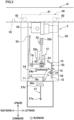
Images




Classifications
-
- B—PERFORMING OPERATIONS; TRANSPORTING
- B65—CONVEYING; PACKING; STORING; HANDLING THIN OR FILAMENTARY MATERIAL
- B65H—HANDLING THIN OR FILAMENTARY MATERIAL, e.g. SHEETS, WEBS, CABLES
- B65H54/00—Winding, coiling, or depositing filamentary material
- B65H54/02—Winding and traversing material on to reels, bobbins, tubes, or like package cores or formers
- B65H54/22—Automatic winding machines, i.e. machines with servicing units for automatically performing end-finding, interconnecting of successive lengths of material, controlling and fault-detecting of the running material and replacing or removing of full or empty cores
- B65H54/26—Automatic winding machines, i.e. machines with servicing units for automatically performing end-finding, interconnecting of successive lengths of material, controlling and fault-detecting of the running material and replacing or removing of full or empty cores having one or more servicing units moving along a plurality of fixed winding units
-
- B—PERFORMING OPERATIONS; TRANSPORTING
- B65—CONVEYING; PACKING; STORING; HANDLING THIN OR FILAMENTARY MATERIAL
- B65H—HANDLING THIN OR FILAMENTARY MATERIAL, e.g. SHEETS, WEBS, CABLES
- B65H67/00—Replacing or removing cores, receptacles, or completed packages at paying-out, winding, or depositing stations
- B65H67/04—Arrangements for removing completed take-up packages and or replacing by cores, formers, or empty receptacles at winding or depositing stations; Transferring material between adjacent full and empty take-up elements
- B65H67/0405—Arrangements for removing completed take-up packages or for loading an empty core
-
- B—PERFORMING OPERATIONS; TRANSPORTING
- B65—CONVEYING; PACKING; STORING; HANDLING THIN OR FILAMENTARY MATERIAL
- B65H—HANDLING THIN OR FILAMENTARY MATERIAL, e.g. SHEETS, WEBS, CABLES
- B65H54/00—Winding, coiling, or depositing filamentary material
- B65H54/70—Other constructional features of yarn-winding machines
- B65H54/702—Arrangements for confining or removing dust
-
- B—PERFORMING OPERATIONS; TRANSPORTING
- B65—CONVEYING; PACKING; STORING; HANDLING THIN OR FILAMENTARY MATERIAL
- B65H—HANDLING THIN OR FILAMENTARY MATERIAL, e.g. SHEETS, WEBS, CABLES
- B65H54/00—Winding, coiling, or depositing filamentary material
- B65H54/70—Other constructional features of yarn-winding machines
- B65H54/707—Suction generating system
-
- B—PERFORMING OPERATIONS; TRANSPORTING
- B65—CONVEYING; PACKING; STORING; HANDLING THIN OR FILAMENTARY MATERIAL
- B65H—HANDLING THIN OR FILAMENTARY MATERIAL, e.g. SHEETS, WEBS, CABLES
- B65H54/00—Winding, coiling, or depositing filamentary material
- B65H54/70—Other constructional features of yarn-winding machines
- B65H54/71—Arrangements for severing filamentary materials
-
- B—PERFORMING OPERATIONS; TRANSPORTING
- B65—CONVEYING; PACKING; STORING; HANDLING THIN OR FILAMENTARY MATERIAL
- B65H—HANDLING THIN OR FILAMENTARY MATERIAL, e.g. SHEETS, WEBS, CABLES
- B65H63/00—Warning or safety devices, e.g. automatic fault detectors, stop-motions ; Quality control of the package
-
- B—PERFORMING OPERATIONS; TRANSPORTING
- B65—CONVEYING; PACKING; STORING; HANDLING THIN OR FILAMENTARY MATERIAL
- B65H—HANDLING THIN OR FILAMENTARY MATERIAL, e.g. SHEETS, WEBS, CABLES
- B65H67/00—Replacing or removing cores, receptacles, or completed packages at paying-out, winding, or depositing stations
- B65H67/08—Automatic end-finding and material-interconnecting arrangements
- B65H67/081—Automatic end-finding and material-interconnecting arrangements acting after interruption of the winding process, e.g. yarn breakage, yarn cut or package replacement
-
- B—PERFORMING OPERATIONS; TRANSPORTING
- B65—CONVEYING; PACKING; STORING; HANDLING THIN OR FILAMENTARY MATERIAL
- B65H—HANDLING THIN OR FILAMENTARY MATERIAL, e.g. SHEETS, WEBS, CABLES
- B65H2701/00—Handled material; Storage means
- B65H2701/30—Handled filamentary material
- B65H2701/31—Textiles threads or artificial strands of filaments
Definitions
- the present invention relates to a doffing device configured to perform doffing for a winding device winding a yarn, and an automatic winder.
- Patent Literature 1 Japanese Laid-Open Patent Publication No. 2018-65659 ) recites a doffing device configured to perform doffing for a winding device winding a yarn.
- the doffing device includes a housing hanging down from a rail extending in a predetermined direction, a wheel which allows the housing to run along the rail, and a suction mouth (suction member) which is attached to the housing to temporarily suck and hold a yarn.
- the suction member has a suction port, and is configured to be able to suck a yarn by generating a negative pressure at the suction port by using a negative pressure source.
- a blower device having a typical blower motor may be mounted on the doffing device.
- the blower motor which is typically heavy is placed at an end portion of the doffing device in the predetermined direction, and this may adversely affect on the balance of the doffing device in the predetermined direction.
- An object of the present invention is to suppress the occurrence of problems in a doffing device, which are caused by the installation of a blower device.
- a doffing device is capable of performing doffing for a winding device configured to wind a yarn, and hangs down from a rail extending in a predetermined direction to be able to run along the rail, the doffing device comprising: a housing; a wheel which is provided above the housing and is configured to allow the housing to run along the rail; a sucking unit which is configured to be able to suck the yarn by a negative pressure; and a blower device which includes a blower motor for generating the negative pressure and is connected to the sucking unit, the blower device being provided below the wheel and being on the inner side of both ends of the housing in the predetermined direction, and when viewed in an orthogonal direction that is orthogonal to both the predetermined direction and an up-down direction, the blower device being disposed, in the predetermined direction, across both sides of a virtual center line passing through a point equidistant from the both ends of the housing and extending in the up-down
- the blower device in the doffing device hanging down from the rail, is provided at a central part in the predetermined direction of the housing, which is below the wheel.
- This allows the center of gravity of the doffing device to be close to the center in the up-down direction and the predetermined direction, as compared to an arrangement in which the blower device is positioned above the wheel or at an end portion in the predetermined direction. It is therefore possible to stably balance the running doffing device.
- it is possible to suppress the cost increase due to, for example, the elongation of the rail. Because of the above, it is possible to suppress the occurrence of problems in the doffing device, which are caused by the installation of the blower device.
- the layout of the pipes and wires connected to the blower device is simplified.
- the doffing device of the first aspect is arranged so that, when the wheel is mounted on the rail, the blower device is provided below the rail, and the distance between the rail and the blower motor in the up-down direction is shorter than the total length of the blower motor in the up-down direction.
- the blower motor is positioned to be remote from the rail, there is a risk that the housing may experience significant vibrations due to the vibration of the blower motor in operation, with the contact portion between the wheel and the rail acting as a fulcrum.
- the blower motor is positioned to be very close to the rail. It is therefore possible to suppress the vibration of the housing. Furthermore, because the blower device is provided below the rail, the operator is able to easily access the blower device in the maintenance of the doffing device hanging down from the rail.
- the doffing device of the first or second aspect is arranged so that the blower device includes a dust box in which a dust yarn is collected by utilizing a negative pressure generated by the blower motor and accumulated, the dust box has an access port which allows an operator to access the inside of the dust box, and the access port is positioned to be accessible from a work passage provided below the rail, when the wheel is mounted on the rail.
- the doffing device of the third aspect further comprises a detachable member which is detachably attached to the blower device and is configured to allow gas to flow to the blower motor side by an operation of the blower device, the access port having an opening portion to which the detachable member is detachably attached, and the opening portion being open to face the work passage, when the detachable member is detached.
- the dust yarn collected into the dust box can be automatically discharged from the dust box by a known waste yarn removal device.
- a known waste yarn removal device there may be a need for the operator to clean the inside of the dust box when a trouble occurs or maintenance is performed. Even in such cases, according to the arrangement of the present invention, the operator can easily access the access port from the work passage. Therefore, the inside of the dust box can be easily cleaned.
- the doffing device of any one of the first to fourth aspects further comprises a pipe member which is connected to the blower device and is configured to allow gas to flow to the blower motor side by an operation of the blower device, the pipe member being at least partially transparent.
- the transparency means that the inside of the at least part of the pipe member can be seen through, and the operator is able to visually check the state of the inside of the pipe member.
- the arrangement of the present invention allows the operator to visually check at least part of the inside of the pipe member with ease, while the blower device is in operation. Therefore, the operator can easily check whether the inside of the pipe member is clogged.
- the invention further provides an automatic winder having a plurality of winding devices that are arranged side by side in the predetermined direction and a doffing device according to the invention, wherein the rail is arranged in an upper region or above the winding devices such that the doffing device hanging down from the rail can be moved to a selected one of the winding devices for performing doffing for the selected winding device.
- the direction in which later-described yarn winding units 2 (winding devices of the present invention) are aligned is referred to as a left-right direction (predetermined direction in the present invention), as shown in FIG. 1 .
- the direction in which gravity acts is referred to as an up-down direction.
- the direction orthogonal to both the left-right direction and the up-down direction is referred to as a front-rear direction (orthogonal direction of the present invention).
- FIG. 1 is a front elevation of the automatic winder 1.
- the automatic winder 1 includes yarn winding units 2, a doffing device 3, a bobbin supplier 4, a waste yarn removal device 5, and a machine controller 6.
- Each of the yarn winding units 2 is configured to form a package P by winding a yarn Y pulled out from a yarn supplying bobbin B onto a take up tube Q (see FIG. 2 ).
- the yarn winding units 2 are aligned in the left-right direction.
- the doffing device 3 is provided above the yarn winding units 2.
- the doffing device 3 is arranged to be movable along rails R extending in the left-right direction.
- the doffing device 3 is configured to perform various processes for each of the yarn winding units 2. The doffing device 3 will be further detailed later.
- the bobbin supplier 4 is configured to be able to supply yarn supplying bobbins B to the yarn winding units 2.
- the bobbin supplier 4 is configured to supply a conveyance tray T supporting a yarn supplying bobbin B to a lower portion of each yarn winding unit 2.
- the waste yarn removal device 5 is a device for removing, for example, waste yarn collected by and accumulated in the doffing device 3, from the doffing device 3.
- the waste yarn removal device 5 is connectable to a rear end portion of the doffing device 3, for example.
- the machine controller 6 is positioned to the left of the yarn winding units 2, for example.
- the machine controller 6 is electrically connected to a unit controller 2a of each yarn winding unit 2 and a doffing controller 3a of the doffing device 3, and communicates with these controllers.
- FIG. 2 is a side view which schematically shows the yarn winding unit 2.
- the right side of the sheet corresponds to the front side in the front-rear direction
- the left side of the sheet corresponds to the rear side in the front-rear direction.
- the yarn winding unit 2 includes a yarn supplying unit 10, a yarn processing unit 20, a yarn storage device 30, and a winding unit 40.
- the yarn supplying unit 10 is arranged to be able to supply a yarn Y wound on a yarn supplying bobbin B.
- the yarn processing unit 20 is configured to be able to carry out various processes for the yarn Y supplied from the yarn supplying unit 10.
- the yarn storage device 30 is configured to temporarily store the yarn Y processed by the yarn processing unit 20.
- the winding unit 40 is configured to be able to form a package P by pulling the yarn Y out from the yarn storage device 30 and winding the yarn Y onto a take up tube Q.
- the yarn supplying unit 10, the yarn processing unit 20, the yarn storage device 30, and the winding unit 40 are aligned in this order from bottom to top.
- the yarn supplying unit 10 includes a yarn unwinding assisting device 11 which is configured to assist unwinding of the yarn Y from the yarn supplying bobbin B.
- the yarn unwinding assisting device 11 is configured to adjust, by an adjusting cylinder 12, a bulge which is formed when the yarn Y is unwound from the yarn supplying bobbin B.
- the yarn processing unit 20 includes an upper yarn capturing unit 21, a yarn joining device 22, a lower yarn capturing unit 23, a tensioner 24, a yarn monitoring device 25, and a guide mechanism 26.
- the upstream side in a yarn running direction in which a yarn Y runs will be simply referred to as an upstream side.
- the downstream side in the yarn running direction will be simply referred to as a downstream side.
- the upper yarn capturing unit 21, the yarn joining device 22, the free end of the lower yarn capturing unit 23 in its position that is indicated in two-dot chain lines in Fig. 2 , the tensioner 24, and the yarn monitoring device 25 are provided in this order from the upstream side to the downstream side.
- a part of the divided yarn Y on the yarn supplying unit 10 side (lower side, i.e., the upstream side) may be termed a lower yarn.
- a part of the divided yarn Y on the winding unit 40 side (upper side, i.e., the downstream side) may be termed an upper yarn.
- the upper yarn capturing unit 21 is configured to suck and capture an upper yarn (in this case, a yarn Y above the yarn joining device 22 and below the yarn storage device 30) and guide the captured yarn to the yarn joining device 22.
- the yarn joining device 22 is configured to perform yarn joining of the divided yarn Y.
- the yarn joining device 22 is configured to join yarn ends that are guided to the yarn joining device 22 by the upper yarn capturing unit 21 and the lower yarn capturing unit 23.
- the lower yarn capturing unit 23 is configured to suck and capture a lower yarn (in this case, a yarn Y below the yarn joining device 22) and guide the captured yarn to the yarn joining device 22.
- the lower yarn capturing unit 23 is able to turn and move an opening at its leading end portion between a position (indicated by solid lines in FIG. 2 ) on the downstream side (upper side) of the adjusting cylinder 12 and a position (indicated by two-dot chain lines in FIG. 2 ) on the downstream side (upper side) of the yarn joining device 22.
- a clamp lid is provided to be put on the opening. By closing this clamp lid, it is possible to prevent the sucking and at the same time to clamp a sucked yarn Y.
- the tensioner 24 is configured to be able to apply a predetermined tension to a running yarn Y.
- the yarn monitoring device 25 is configured to detect a defect (yarn defect) in a yarn Y and cut the yarn Y.
- the guide mechanism 26 is configured to be able to guide a yarn (upper yarn) on the winding unit 40 side to the upper yarn capturing unit 21 when the yarn Y is divided between the yarn supplying unit 10 and the winding unit 40.
- the yarn storage device 30 is configured to be able to pull a yarn Y out from the yarn supplying unit 10 and temporarily store the yarn Y by winding the yarn Y onto a yarn storage roller 31.
- the winding unit 40 includes a cradle 41, a traversing drum 42, and a traverse guide 43.
- the winding unit 40 traverses the yarn Y by the traversing drum 42 while causing the take up tube Q attached to the cradle 41 to be passively rotated by the traversing drum 42. With this, the winding unit 40 forms a package P by winding the yarn Y onto the rotating take up tube Q while traversing the yarn Y.
- each yarn winding unit 2 includes a unit controller 2a.
- the unit controller 2a includes, for example, a CPU, a ROM, and a RAM.
- the unit controller 2a controls the operation of each of the yarn supplying unit 10, the yarn processing unit 20, the yarn storage device 30, and the winding unit 40.
- Each unit controller 2a is configured to be able to communicate with the machine controller 6.
- FIG. 3 shows the doffing device 3 which is viewed from the yarn winding unit 2 side (i.e., the rear side) in the front-rear direction. Please note that the left-right direction in FIG. 3 is opposite to the left-right direction of the sheet.
- the doffing device 3 is configured to perform processes such as a doffing process (doffing), a type change process, and an upper yarn breakage dealing process by operating in conjunction with the yarn winding unit 2.
- the doffing process is a process to replace a package P finished at a yarn winding unit 2 with a new empty take up tube Q.
- the type change process is a process to change the type of the yarn Y wound by the winding unit 40.
- the upper yarn breakage dealing process is a process performed when a yarn Y is divided between a package P and the yarn storage device 30 in the yarn running direction, in order to pull a yarn Y (upper yarn) out from the package P and guide the yarn Y to the guide mechanism 26.
- the doffing device 3 includes, for example, a housing 50, a multifunction arm 51, a chuck 52, a cradle opener 53, a suction mouth 54 (sucking unit of the present invention), a seed yarn supplier 55, a vertical guide lever 56, a yarn skipping lever 57, a blower device 58, and a running unit 59.
- the housing 50 is a box-shaped member that extends to be long in, for example, the up-down direction.
- the housing 50 is roughly rectangular in shape when viewed in the front-rear direction, for example. The positions of both ends in the left-right direction of the housing 50 are therefore defined.
- the housing 50 is provided below the rails R, for example.
- the housing 50 has an opening in a rear surface.
- the members such as the multifunction arm 51, the chuck 52, the cradle opener 53, the suction mouth 54, the seed yarn supplier 55, the vertical guide lever 56, the yarn skipping lever 57, and the blower device 58 are, for example, accommodated in or attached to the housing 50.
- the multifunction arm 51 is used for all of the doffing process, the type change process, and the upper yarn breakage dealing process.
- the multifunction arm 51 has an arm portion 61, a guide portion 62, and a clamp cutter portion 63.
- the multifunction arm 51 is arranged to be able to guide and/or to cut and hold the yarn Y in various situations by driving the guide portion 62 and the clamp cutter portion 63 attached to the leading end portion of the arm portion 61.
- the arm portion 61 is configured to be swung in various directions by, for example, multiple unillustrated motors.
- the guide portion 62 is configured to be able to guide the yarn Y.
- the guide portion 62 is configured to be swung by, for example, an unillustrated motor.
- the clamp cutter portion 63 includes an unillustrated cutter for cutting the yarn Y and an unillustrated clamp for holding the yarn Y.
- the clamp cutter portion 63 is configured, for example, to perform the cutting of the yarn Y and the holding of a yarn end of the yarn Y having been cut, substantially simultaneously, by an unillustrated air cylinder.
- the multifunction arm 51 is preferably provided, for example, below the chucking portion 52b.
- the chuck 52 is used for the doffing process and the type change process.
- the chuck 52 is attached to the shaft 52a extending in the left-right direction to be rotatable in the housing 50.
- the chuck 52 is, for example, rotationally driven about the shaft 52a by an unillustrated motor.
- the chucking portion 52b is provided to be able to grip a take up tube Q.
- the chuck 52 takes an empty take up tube Q out from an unillustrated stocker at an upper end portion of the automatic winder 1, grips the take up tube Q at the chucking portion 52b, and rotates downward.
- the empty take up tube Q is positioned in the vicinity of the cradle 41.
- the cradle opener 53 is used for the doffing process and the type change process.
- the cradle opener 53 is, for example, provided in the vicinity of a right end portion of the housing 50.
- the cradle opener 53 is driven by, e.g., a suitable driving source such as an air cylinder or a motor.
- the cradle opener 53 performs various operations such as swinging and rotating, and operates an unillustrated cradle lever provided on the cradle 41.
- a package P becomes detachable from the cradle 41.
- an empty take up tube Q becomes attachable to the cradle 41.
- the suction mouth 54 is configured to be able to suck and hold a yarn end of the yarn Y (upper yarn) wound on the package P, when, for example, the type change process and the upper yarn breakage dealing process are performed.
- the suction mouth 54 is provided at a position substantially identical with that of the package P in the up-down direction.
- a suction port 54a extending in the left-right direction is provided at the rear end of the suction mouth 54.
- the suction mouth 54 is configured to be movable between a standby position and a near position that is close to the yarn winding unit 2 as compared to the standby position.
- the suction mouth 54 is connected to the blower device 58.
- the suction mouth 54 is able to suck and hold the yarn Y by a negative pressure generated at the suction port 54a by the blower device 58.
- a mouth cutter 54b is provided to be able to cut the yarn Y.
- the seed yarn supplier 55 is configured to be able to supply a yarn Y of a new type in the type change process.
- a yarn Y of a new type supplied from the seed yarn supplier 55 will be referred to as a seed yarn Ys for convenience.
- the seed yarn supplier 55 includes a seed yarn bobbin supporter 71, a seed yarn blowing nozzle 72, a seed yarn guide pipe 73, a seed yarn suction 74 (sucking unit of the present invention), and a seed yarn clamp cutter 75.
- the seed yarn bobbin supporter 71 is, for example, provided in the vicinity of the right end portion of the housing 50.
- the seed yarn bobbin supporter 71 is configured to, for example, substantially horizontally support a seed yarn bobbin Bs on which the seed yarn Ys has been wound.
- the seed yarn blowing nozzle 72 is configured to blow a yarn end of the seed yarn Ys upward, for example.
- the seed yarn guide pipe 73 is configured to guide, toward the seed yarn suction 74, the yarn end of the seed yarn Ys blown by the seed yarn blowing nozzle 72.
- the seed yarn suction 74 is configured to be able to suck and capture the yarn end of the seed yarn Ys.
- the seed yarn suction 74 has a suction port (not illustrated) that is open rearward, for example.
- the seed yarn suction 74 is connected to the blower device 58.
- the seed yarn suction 74 sucks and captures the yarn end of the seed yarn Ys jutting out from the exit of the seed yarn guide pipe 73 by utilizing a negative pressure.
- the seed yarn Ys sucked and captured by the seed yarn suction 74 is then cut and held by, for example, the seed yarn clamp cutter 75.
- the vertical guide lever 56 is used in the type change process and the upper yarn breakage dealing process.
- the vertical guide lever 56 is mainly used to pull the yarn Y downward.
- the vertical guide lever 56 is provided, for example, in the vicinity of the suction mouth 54 and the seed yarn supplier 55, as shown in FIG. 3 .
- the vertical guide lever 56 is positioned, for example, immediately behind the housing 50.
- the vertical guide lever 56 is configured to be rotatable about a rotation shaft 56a extending at least in the front-rear direction.
- the yarn skipping lever 57 is used in the type change process and the upper yarn breakage dealing process.
- the yarn skipping lever 57 is arranged to be swingable about a swing shaft 57a which extends in the left-right direction, for example.
- the swing shaft 57a is provided at the lowest end portion of the doffing device 3, for example.
- a yarn picking portion 57b is provided to pick up the yarn Y.
- the yarn skipping lever 57 picks up, by the yarn picking portion 57b, the yarn Y which is pulled downward by the vertical guide lever 56, and guides the yarn Y to the guide mechanism 26 (see FIG. 2 ).
- the blower device 58 is configured to be able to generate a negative pressure in the suction mouth 54 and the seed yarn suction 74 described above, for example. The details of the blower device 58 will be given later.
- the running unit 59 (see FIG. 3 to FIG. 6 ) is configured to cause the housing 50 to run along two rails R extending in the left-right direction, for example.
- Each rail R is, e.g., substantially C-shaped in a cross section orthogonal to the left-right direction, for example (see FIG. 5 ).
- Each rail R has a mounting surface R1 on which later-described wheels 82 are mounted.
- Below the two rails R there is a work passage 7 (see FIG. 1 and FIG. 2 ) that allows operators to pass therethrough.
- the work passage 7 includes, for example, a floor surface 7a on which the operators can walk and a working space Sw immediately above the floor surface 7a (see FIG. 2 ).
- the doffing device 3 includes a doffing controller 3a.
- the doffing controller 3a includes, for example, a CPU, a ROM, and a RAM.
- the doffing controller 3a is configured to be able to communicate with the machine controller 6.
- the doffing controller 3a controls the sections of the doffing device 3 based on instructions from the machine controller 6.
- the doffing process As the yarn winding unit 2 operates in conjunction with the doffing device 3, the doffing process, the type change process, and the upper yarn breakage dealing process are performed.
- the doffing controller 3a and the unit controller 2a exchange signals through, for example, the machine controller 6. The following will describe the outline of each of these processes.
- the doffing process will be outlined. For example, when the formation of a package P is completed at a winding unit 2, the unit controller 2a stops the rotation of the traversing drum 42 and the yarn storage roller 31. At this stage, the yarn Y is still connected between the package P and the yarn storage device 30. Subsequently, the unit controller 2a transmits a signal requesting the doffing process to the doffing controller 3a through the machine controller 6. The doffing controller 3a moves the doffing device 3 to the front of the yarn winding unit 2. The doffing controller 3a moves the clamp cutter portion 63 to a position where the yarn Y can be cut and held, and causes the clamp cutter portion 63 to cut and hold the yarn Y.
- the unit controller 2a rotates the traversing drum 42 and winds a part of the yarn Y on the winding unit 40 side onto the package P.
- the doffing controller 3a causes the cradle opener 53 to operate the cradle 41.
- the package P is released from the cradle 41.
- the doffing controller 3a moves the clamp cutter portion 63 to a position where the yarn Y can be interposed between a new take up tube Q and the cradle 41.
- the doffing controller 3a then controls the chuck 52 to attach an empty take up tube Q to the cradle 41.
- the doffing controller 3a causes the cradle opener 53 to operate the cradle 41, so as to fix the yarn Y held by the clamp cutter portion 63 to the take up tube Q. Furthermore, the doffing controller 3a performs bunch winding to wind the yarn Y onto an end portion of the take up tube Q. Thanks to this doffing process, it becomes possible to resume the winding of the yarn Y.
- a starter package (not illustrated) is formed on the take up tube Q.
- the doffing controller 3a cuts the seed yarn Ys between the seed yarn bobbin Bs and the starter package by, for example, controlling the multifunction arm 51.
- the doffing controller 3a causes the suction mouth 54 to pull the seed yarn Ys out from the starter package.
- the doffing controller 3a controls the vertical guide lever 56 and the yarn skipping lever 57 to guide the seed yarn Ys to the guide mechanism 26.
- the upper yarn breakage dealing process will be outlined.
- the upper yarn breakage is cutting of the yarn Y between the yarn storage device 30 and the package P in the yarn running direction, due to a trouble.
- the upper yarn breakage dealing process is roughly divided into two processes, i.e., a remaining yarn removal process and an upper yarn guide process.
- the remaining yarn removal process is a process of removing the remaining yarn wound on the yarn storage device 30.
- the operator may perform the remaining yarn removal process.
- the upper yarn guide process is a process similar to the above-described type change process. That is to say, the doffing controller 3a causes the suction mouth 54 to pull the yarn Y out from the package P in production.
- the blower device 58 is a device that is configured to generate a suction force by using a negative pressure, for example, at the suction mouth 54 and the seed yarn suction 74. As shown in FIG. 4 to FIG. 8 , the blower device 58 includes, for example, a base 91, a blower motor 92, an impeller member 93, and a dust box 94. The impeller member 93 and the dust box 94 are attached to the base 91.
- the blower motor 92 is a motor configured to rotationally drive an impeller 93b (described later) provided in the impeller member 93.
- the blower motor 92 is, for example, arranged on the opposite side of the base 91 over the impeller member 93 in the left-right direction.
- the blower motor 92 is attached to a left side surface of the casing 93a (described later) of the impeller member 93, for example.
- the blower motor 92 has a housing 92a that accommodates various members, for example.
- the impeller member 93 is configured to suck the air (gas) on the base 91 side and discharge the air to the outside space.
- the impeller member 93 is, for example, provided between the base 91 and the blower motor 92 in the left-right direction.
- the impeller member 93 includes, for example, the casing 93a and the impeller 93b.
- the casing 93a is a cylindrical box-shaped member, for example.
- the impeller 93b is accommodated in the casing 93a to be rotatable.
- exhaust ports 93c are formed to be aligned in the circumferential direction of the casing 93a.
- Each exhaust port 93c allows the internal space of the casing 93a to communicate with the outside space of the casing 93a.
- the impeller 93 is configured to rotate to discharge the gas on the base 91 side to the outside space of the casing 93a. More specifically, for example, a known vortex impeller is employed as the impeller 93b.
- the vortex impeller is an impeller used, for example, in a known centrifugal pump.
- the impeller 93b is rotationally driven by the blower motor 92.
- the impeller 93b rotates to suck the gas in the internal space of the casing 93a and discharges the gas to the outside in the radial direction of the impeller 93b (i.e., to the outside space of the casing 93a) through the exhaust ports 93c.
- This generates a negative pressure in, for example, the internal space of the dust box 94 which is connected to the internal space of the base 91.
- the dust box 94 is a box-shaped member that is designed to be able to collect and accumulate the waste yarn Yw and unillustrated cotton fly (fiber waste floating in the space where the automatic winder 1 is installed).
- the dust box 94 is attached to, for example, a right side face of the base 91.
- a suction port 94a an access port of the present invention; see FIG. 7 and FIG. 8 ) is formed to suck air including the dust yarn Yw.
- the dust box 94 is connected to the suction mouth 54 through the suction port 94a and the pipe 95.
- a box-shaped relay member 98 (see FIG. 5 ) is provided between, for example, the pipe 95 and the suction port 94a.
- a shutter (not illustrated) may be provided to be able to allow and prohibit the air in the pipe 95 to flow toward the dust box 94 side, for example.
- the dust box 94 is connected to the seed yarn suction 74 through the suction port 94a and the pipe 96 (a pipe member of the present invention).
- the relay member 98 is provided between, for example, the pipe 96 and the suction port 94a.
- a shutter (not illustrated) may be provided to be able to allow and prohibit the air in the pipe 96 to flow toward the dust box 94 side, for example.
- the pipe 96 is at least partially transparent.
- the transparency of the pipe 96 means that the inside of the at least part of the pipe 96 can be seen through, and the operator is able to visually check the state of the inside.
- the at least part of the pipe 96 may be colored, for example.
- a part in the longitudinal direction of the pipe 96 is made of a transparent material such as acrylic. This arrangement allows the operator to visually check at least part of the inside of the pipe 96 with ease, while the blower device 58 is in operation (see FIG. 7 ).
- the pipe 95 may be at least partially transparent.
- the detachable pipe 97 (see FIG. 5 to FIG. 8 ) is provided between, for example, the suction port 94a and the relay member 98.
- the detachable pipe 97 is arranged to be attachable to and detachable from at least the dust box 94.
- the detachable pipe 97 may be attachable to and detachable from both the dust box 94 and the relay member 98 (see FIG. 8 ).
- the detachable pipe 97 is, for example, positioned in front of the dust box 94. This allows the operator to access the detachable pipe 97 from the front side (work passage 7 side).
- the detachable pipe 97 is at least partially transparent.
- connection pipe 94b is formed to connect the waste yarn removal device 5 (see FIG. 1 ) with the dust box 94.
- the connection pipe 94b is configured to be openable and closable by a shutter mechanism 94c having, for example, an unillustrated shutter. The shutter is closed when the blower device 58 is in operation. When the shutter is open, the cotton fly in the dust box 94 can be removed by the waste yarn removal device 5.
- the blower motor 92 rotationally drives the impeller wheel 93b, with the result that the gas in the base 91 and the gas in the dust box 94, for example, are sucked into the impeller member 93 and discharged to the outside space.
- This generates a negative pressure around the suction port 54a of the suction mouth 54 through the dust box 94 and the pipe 95, and hence the yarn Y around the suction port 54a is sucked.
- the above-described arrangement generates a negative pressure around the suction port of the seed yarn suction 74 through the dust box 94 and the pipe 96, and hence the yarn Y around the suction port is sucked.
- the yarn Y sucked and removed by the suction mouth 54 or the seed yarn suction 74 is collected into the dust box 94 through the suction port 94a, as the waste yarn Yw.
- the cotton fly is also collected into the dust box 94.
- the air sucked into the dust box 94 flows through the filter 91a toward the impeller member 93 side, and is discharged to the outside space through the exhaust ports 93c (see, e.g., a dotted arrow in FIG. 6 ).
- the movement of the waste yarn Yw and the cotton fly (hereinafter, waste yarn Yw, etc.) towards the impeller member 93 is blocked by the filter 91a. For this reason, the waste yarn Yw, etc.
- the suction port 94a can be exposed to the outside by detaching the detachable pipe 97 from the dust box 94 (see FIG. 8 ) . This allows the operator to access the inside of the dust box 94 through the suction port 94a and remove the waste yarn Yw, etc. inside the dust box 94.
- the blower device 58 is arranged substantially at the center of the doffing device 3 in the left-right direction. More specifically, the following assumes that the doffing device 3 hangs down from the rails R (i.e., the doffing device 3 is disposed so that wheels 82 are mounted on the rails R). At this time, the blower device 58 is positioned below the rails R and the wheels 82, for example. The blower device 58 is provided on the inner side of the both ends in the left-right direction of the housing 50.
- the position of the left end of the housing 50 will be referred to a position PL, whereas the position of the right end will be referred to as a position PR.
- a virtual straight line which passes through a point that is equidistant from the positions PL and PR in the left-right direction and extends in the up-down direction when viewed in the front-rear direction will be referred to as a virtual center line VLc.
- the blower device 58 is disposed across the both sides of the virtual center line VLc in the left-right direction.
- the blower device 58 is, for example, provided above the chuck 52 (see FIG. 3 ).
- the blower motor 92 is positioned immediately below the rails R.
- the interval (i.e., the shortest distance in the up-down direction) between the rails R and the blower motor 92 is defined as an interval D.
- the total length of the blower motor 92 in the up-down direction is defined as a total length Lt. More specifically, the total length Lt may be defined by, for example, the length in the up-down direction of the housing 92a.
- the interval D is shorter than the total length Lt, for example.
- the blower motor 92 is positioned in the vicinity of the rails R in the up-down direction (in other words, in the vicinity of the wheels 82).
- the blower device 58 is provided at a central part in the left-right direction of the housing 50, which is below the wheels 82. This allows the center of gravity of the doffing device 3 to be close to the center in the up-down direction and the left-right direction, as compared to an arrangement in which the blower device 58 is positioned, for example, above the wheels 82 or at an end portion in the left-right direction. It is therefore possible to stably balance the running doffing device 3.
- the blower device 58 is placed outside the housing 50 in the left-right direction, it is possible to suppress the cost increase due to, for example, the elongation of the rails R. Because of the above, it is possible to suppress the occurrence of problems in the doffing device 3, which are caused by the installation of the blower device 58. Furthermore, as compared to an arrangement in which the blower device 58 is positioned above the wheels 82 or at an end portion in the left-right direction, the layout of the pipes and wires connected to the blower device 58 is simplified.
- the blower motor 92 is positioned to be very close to the rails R. If the blower motor 92 is positioned to be remote from the rails R, there is a risk that the housing 50 may experience significant vibrations due to the vibration of the blower motor 92 in operation, with the contact portion between the wheel 82 and the rail R acting as a fulcrum. In this regard, according to the present embodiment, the vibration of the housing 50 caused by the vibration of the blower motor 92 can be reduced as compared to the configuration where the blower motor 92 is positioned to be remote from the rails R. Furthermore, because the blower device 58 is provided below the rails R, the operator is able to easily access the blower device 58 in the maintenance of the doffing device 3 hanging down from the rails R.
- the suction port 94a of the dust box 94 is positioned to be accessible from the work passage 7. More specifically, the suction port 94a of the dust box 94 has a circular opening portion that allows the detachable pipe 97 to be attached and detached. When the detachable pipe 97 has been detached from the opening portion, the circular opening portion is open to face the work passage 7. This allows the operator to easily access the suction port 94a. Therefore, the inside of the dust box 94 can be easily cleaned.
- the detachable pipe 96 is at least partially transparent. This arrangement allows the operator to visually check at least part of the inside of the pipe 96 with ease, while the blower device 58 is in operation. Therefore, the operator can easily check whether the inside of the pipe 96 is clogged.
Landscapes
- Engineering & Computer Science (AREA)
- Textile Engineering (AREA)
- Quality & Reliability (AREA)
- Spinning Or Twisting Of Yarns (AREA)
- Replacing, Conveying, And Pick-Finding For Filamentary Materials (AREA)
Abstract
The occurrence of problems in a doffing device, which are caused by the installation of a blower device, is avoided. A doffing device 3 includes a housing 50, wheels 82, a suction mouth 54, a seed yarn suction 74, and a blower device 58. The suction mouth 54 and the seed yarn suction 74 are configured to be able to suck a yarn Y by a negative pressure. The blower device 58 has a blower motor 92 to generate the negative pressure, and is connected to the suction mouth 54 and the seed yarn suction 74. The blower device 58 is provided below the wheel 82 and is on the inner side of both ends of the housing 50 in the left-right direction, and when viewed in the front-rear direction, the blower device 58 is disposed across the both sides of a virtual center line VLc in the left-right direction.
Description
- The present invention relates to a doffing device configured to perform doffing for a winding device winding a yarn, and an automatic winder.
- Patent Literature 1 (
Japanese Laid-Open Patent Publication No. 2018-65659 - As the negative pressure source, a blower device having a typical blower motor may be mounted on the doffing device. In this case, it is conceivable to provide the blower outside the housing in a predetermined direction. However, with this configuration, the blower motor which is typically heavy is placed at an end portion of the doffing device in the predetermined direction, and this may adversely affect on the balance of the doffing device in the predetermined direction. In addition, there may be a need to lengthen the rail to support the blower, and this may increase the cost.
- An object of the present invention is to suppress the occurrence of problems in a doffing device, which are caused by the installation of a blower device.
- According to a first aspect of the invention, a doffing device is capable of performing doffing for a winding device configured to wind a yarn, and hangs down from a rail extending in a predetermined direction to be able to run along the rail, the doffing device comprising: a housing; a wheel which is provided above the housing and is configured to allow the housing to run along the rail; a sucking unit which is configured to be able to suck the yarn by a negative pressure; and a blower device which includes a blower motor for generating the negative pressure and is connected to the sucking unit, the blower device being provided below the wheel and being on the inner side of both ends of the housing in the predetermined direction, and when viewed in an orthogonal direction that is orthogonal to both the predetermined direction and an up-down direction, the blower device being disposed, in the predetermined direction, across both sides of a virtual center line passing through a point equidistant from the both ends of the housing and extending in the up-down direction.
- According to the arrangement of the present invention, in the doffing device hanging down from the rail, the blower device is provided at a central part in the predetermined direction of the housing, which is below the wheel. This allows the center of gravity of the doffing device to be close to the center in the up-down direction and the predetermined direction, as compared to an arrangement in which the blower device is positioned above the wheel or at an end portion in the predetermined direction. It is therefore possible to stably balance the running doffing device. Furthermore, it is possible to suppress the cost increase due to, for example, the elongation of the rail. Because of the above, it is possible to suppress the occurrence of problems in the doffing device, which are caused by the installation of the blower device. Furthermore, as compared to an arrangement in which the blower device is positioned above the wheel or at an end portion in the predetermined direction, the layout of the pipes and wires connected to the blower device is simplified.
- According to a second aspect of the invention, the doffing device of the first aspect is arranged so that, when the wheel is mounted on the rail, the blower device is provided below the rail, and the distance between the rail and the blower motor in the up-down direction is shorter than the total length of the blower motor in the up-down direction.
- If the blower motor is positioned to be remote from the rail, there is a risk that the housing may experience significant vibrations due to the vibration of the blower motor in operation, with the contact portion between the wheel and the rail acting as a fulcrum. According to the arrangement of the present invention, the blower motor is positioned to be very close to the rail. It is therefore possible to suppress the vibration of the housing. Furthermore, because the blower device is provided below the rail, the operator is able to easily access the blower device in the maintenance of the doffing device hanging down from the rail.
- According to a third aspect of the invention, the doffing device of the first or second aspect is arranged so that the blower device includes a dust box in which a dust yarn is collected by utilizing a negative pressure generated by the blower motor and accumulated, the dust box has an access port which allows an operator to access the inside of the dust box, and the access port is positioned to be accessible from a work passage provided below the rail, when the wheel is mounted on the rail. According to a fourth aspect of the invention, the doffing device of the third aspect further comprises a detachable member which is detachably attached to the blower device and is configured to allow gas to flow to the blower motor side by an operation of the blower device, the access port having an opening portion to which the detachable member is detachably attached, and the opening portion being open to face the work passage, when the detachable member is detached.
- Typically, the dust yarn collected into the dust box can be automatically discharged from the dust box by a known waste yarn removal device. However, there may be a need for the operator to clean the inside of the dust box when a trouble occurs or maintenance is performed. Even in such cases, according to the arrangement of the present invention, the operator can easily access the access port from the work passage. Therefore, the inside of the dust box can be easily cleaned.
- According to a fifth aspect of the invention, the doffing device of any one of the first to fourth aspects further comprises a pipe member which is connected to the blower device and is configured to allow gas to flow to the blower motor side by an operation of the blower device, the pipe member being at least partially transparent.
- The transparency means that the inside of the at least part of the pipe member can be seen through, and the operator is able to visually check the state of the inside of the pipe member. The arrangement of the present invention allows the operator to visually check at least part of the inside of the pipe member with ease, while the blower device is in operation. Therefore, the operator can easily check whether the inside of the pipe member is clogged.
- The invention further provides an automatic winder having a plurality of winding devices that are arranged side by side in the predetermined direction and a doffing device according to the invention, wherein the rail is arranged in an upper region or above the winding devices such that the doffing device hanging down from the rail can be moved to a selected one of the winding devices for performing doffing for the selected winding device.
-
-
FIG. 1 is a front elevation of an automatic winder of the present embodiment. -
FIG. 2 is a side view which schematically shows a yarn winding unit. -
FIG. 3 shows a doffing device which is viewed from the yarn winding unit side in a front-rear direction. -
FIG. 4 is an enlarged view of an upper part of the doffing device shown inFIG. 3 . -
FIG. 5 is a side view of the doffing device. -
FIG. 6 is a plan view of the doffing device. -
FIG. 7 is a front elevation of a blower device. -
FIG. 8 is an explanatory diagram showing a state in which a detachable pipe has been detached from the blower device. - The following will describe an embodiment of the present invention. For convenience of explanation, the direction in which later-described yarn winding units 2 (winding devices of the present invention) are aligned is referred to as a left-right direction (predetermined direction in the present invention), as shown in
FIG. 1 . The direction in which gravity acts is referred to as an up-down direction. The direction orthogonal to both the left-right direction and the up-down direction is referred to as a front-rear direction (orthogonal direction of the present invention). - The following will describe a schematic structure of an automatic winder 1 of the present embodiment, with reference to
FIG. 1. FIG. 1 is a front elevation of the automatic winder 1. As shown inFIG. 1 , the automatic winder 1 includesyarn winding units 2, adoffing device 3, abobbin supplier 4, a wasteyarn removal device 5, and amachine controller 6. - Each of the
yarn winding units 2 is configured to form a package P by winding a yarn Y pulled out from a yarn supplying bobbin B onto a take up tube Q (seeFIG. 2 ). Theyarn winding units 2 are aligned in the left-right direction. - The
doffing device 3 is provided above theyarn winding units 2. Thedoffing device 3 is arranged to be movable along rails R extending in the left-right direction. Thedoffing device 3 is configured to perform various processes for each of theyarn winding units 2. Thedoffing device 3 will be further detailed later. - The
bobbin supplier 4 is configured to be able to supply yarn supplying bobbins B to theyarn winding units 2. Thebobbin supplier 4 is configured to supply a conveyance tray T supporting a yarn supplying bobbin B to a lower portion of eachyarn winding unit 2. - The waste
yarn removal device 5 is a device for removing, for example, waste yarn collected by and accumulated in thedoffing device 3, from thedoffing device 3. The wasteyarn removal device 5 is connectable to a rear end portion of thedoffing device 3, for example. - The
machine controller 6 is positioned to the left of theyarn winding units 2, for example. Themachine controller 6 is electrically connected to aunit controller 2a of eachyarn winding unit 2 and a doffing controller 3a of thedoffing device 3, and communicates with these controllers. - The following will describe an example of the structure of each
yarn winding unit 2 with reference toFIG. 2. FIG. 2 is a side view which schematically shows theyarn winding unit 2. InFIG. 2 , the right side of the sheet corresponds to the front side in the front-rear direction, whereas the left side of the sheet corresponds to the rear side in the front-rear direction. - As shown in
FIG. 2 , theyarn winding unit 2 includes ayarn supplying unit 10, ayarn processing unit 20, ayarn storage device 30, and a windingunit 40. Theyarn supplying unit 10 is arranged to be able to supply a yarn Y wound on a yarn supplying bobbin B. Theyarn processing unit 20 is configured to be able to carry out various processes for the yarn Y supplied from theyarn supplying unit 10. Theyarn storage device 30 is configured to temporarily store the yarn Y processed by theyarn processing unit 20. The windingunit 40 is configured to be able to form a package P by pulling the yarn Y out from theyarn storage device 30 and winding the yarn Y onto a take up tube Q. Theyarn supplying unit 10, theyarn processing unit 20, theyarn storage device 30, and the windingunit 40 are aligned in this order from bottom to top. - The
yarn supplying unit 10 includes a yarnunwinding assisting device 11 which is configured to assist unwinding of the yarn Y from the yarn supplying bobbin B. To be more specific, the yarnunwinding assisting device 11 is configured to adjust, by an adjustingcylinder 12, a bulge which is formed when the yarn Y is unwound from the yarn supplying bobbin B. - As shown in
FIG. 2 , theyarn processing unit 20 includes an upperyarn capturing unit 21, ayarn joining device 22, a loweryarn capturing unit 23, atensioner 24, ayarn monitoring device 25, and aguide mechanism 26. Hereinafter, the upstream side in a yarn running direction in which a yarn Y runs will be simply referred to as an upstream side. The downstream side in the yarn running direction will be simply referred to as a downstream side. The upperyarn capturing unit 21, theyarn joining device 22, the free end of the loweryarn capturing unit 23 in its position that is indicated in two-dot chain lines inFig. 2 , thetensioner 24, and theyarn monitoring device 25 are provided in this order from the upstream side to the downstream side. When a yarn Y is divided between theyarn supplying unit 10 and the windingunit 40, a part of the divided yarn Y on theyarn supplying unit 10 side (lower side, i.e., the upstream side) may be termed a lower yarn. On the other hand, a part of the divided yarn Y on the windingunit 40 side (upper side, i.e., the downstream side) may be termed an upper yarn. - The upper
yarn capturing unit 21 is configured to suck and capture an upper yarn (in this case, a yarn Y above theyarn joining device 22 and below the yarn storage device 30) and guide the captured yarn to theyarn joining device 22. Theyarn joining device 22 is configured to perform yarn joining of the divided yarn Y. To be more specific, theyarn joining device 22 is configured to join yarn ends that are guided to theyarn joining device 22 by the upperyarn capturing unit 21 and the loweryarn capturing unit 23. The loweryarn capturing unit 23 is configured to suck and capture a lower yarn (in this case, a yarn Y below the yarn joining device 22) and guide the captured yarn to theyarn joining device 22. To be more specific, by an unillustrated drive unit, the loweryarn capturing unit 23 is able to turn and move an opening at its leading end portion between a position (indicated by solid lines inFIG. 2 ) on the downstream side (upper side) of the adjustingcylinder 12 and a position (indicated by two-dot chain lines inFIG. 2 ) on the downstream side (upper side) of theyarn joining device 22. At the leading end portion, a clamp lid is provided to be put on the opening. By closing this clamp lid, it is possible to prevent the sucking and at the same time to clamp a sucked yarn Y. Thetensioner 24 is configured to be able to apply a predetermined tension to a running yarn Y. Theyarn monitoring device 25 is configured to detect a defect (yarn defect) in a yarn Y and cut the yarn Y. Theguide mechanism 26 is configured to be able to guide a yarn (upper yarn) on the windingunit 40 side to the upperyarn capturing unit 21 when the yarn Y is divided between theyarn supplying unit 10 and the windingunit 40. - The
yarn storage device 30 is configured to be able to pull a yarn Y out from theyarn supplying unit 10 and temporarily store the yarn Y by winding the yarn Y onto ayarn storage roller 31. - As shown in
FIG. 2 , the windingunit 40 includes acradle 41, a traversingdrum 42, and atraverse guide 43. The windingunit 40 traverses the yarn Y by the traversingdrum 42 while causing the take up tube Q attached to thecradle 41 to be passively rotated by the traversingdrum 42. With this, the windingunit 40 forms a package P by winding the yarn Y onto the rotating take up tube Q while traversing the yarn Y. - As shown in
FIG. 2 , eachyarn winding unit 2 includes aunit controller 2a. Theunit controller 2a includes, for example, a CPU, a ROM, and a RAM. Theunit controller 2a controls the operation of each of theyarn supplying unit 10, theyarn processing unit 20, theyarn storage device 30, and the windingunit 40. Eachunit controller 2a is configured to be able to communicate with themachine controller 6. - For more details of each constituent feature of the above-described
yarn winding unit 2, seeJapanese Laid-Open Patent Publication No. 2018-65659 - The following will outline the structure of the
doffing device 3 mainly with reference toFIG. 3. FIG. 3 shows thedoffing device 3 which is viewed from theyarn winding unit 2 side (i.e., the rear side) in the front-rear direction. Please note that the left-right direction inFIG. 3 is opposite to the left-right direction of the sheet. - The
doffing device 3 is configured to perform processes such as a doffing process (doffing), a type change process, and an upper yarn breakage dealing process by operating in conjunction with theyarn winding unit 2. The doffing process is a process to replace a package P finished at ayarn winding unit 2 with a new empty take up tube Q. The type change process is a process to change the type of the yarn Y wound by the windingunit 40. The upper yarn breakage dealing process is a process performed when a yarn Y is divided between a package P and theyarn storage device 30 in the yarn running direction, in order to pull a yarn Y (upper yarn) out from the package P and guide the yarn Y to theguide mechanism 26. - The
doffing device 3 includes, for example, ahousing 50, amultifunction arm 51, achuck 52, acradle opener 53, a suction mouth 54 (sucking unit of the present invention), aseed yarn supplier 55, avertical guide lever 56, ayarn skipping lever 57, ablower device 58, and a runningunit 59. - The
housing 50 is a box-shaped member that extends to be long in, for example, the up-down direction. Thehousing 50 is roughly rectangular in shape when viewed in the front-rear direction, for example. The positions of both ends in the left-right direction of thehousing 50 are therefore defined. Thehousing 50 is provided below the rails R, for example. Thehousing 50 has an opening in a rear surface. The members such as themultifunction arm 51, thechuck 52, thecradle opener 53, thesuction mouth 54, theseed yarn supplier 55, thevertical guide lever 56, theyarn skipping lever 57, and theblower device 58 are, for example, accommodated in or attached to thehousing 50. - The
multifunction arm 51 is used for all of the doffing process, the type change process, and the upper yarn breakage dealing process. Themultifunction arm 51 has anarm portion 61, aguide portion 62, and aclamp cutter portion 63. Themultifunction arm 51 is arranged to be able to guide and/or to cut and hold the yarn Y in various situations by driving theguide portion 62 and theclamp cutter portion 63 attached to the leading end portion of thearm portion 61. - The
arm portion 61 is configured to be swung in various directions by, for example, multiple unillustrated motors. Theguide portion 62 is configured to be able to guide the yarn Y. Theguide portion 62 is configured to be swung by, for example, an unillustrated motor. Theclamp cutter portion 63 includes an unillustrated cutter for cutting the yarn Y and an unillustrated clamp for holding the yarn Y. Theclamp cutter portion 63 is configured, for example, to perform the cutting of the yarn Y and the holding of a yarn end of the yarn Y having been cut, substantially simultaneously, by an unillustrated air cylinder. - When a chucking
portion 52b of thechuck 52 is accommodated in thehousing 50, themultifunction arm 51 is preferably provided, for example, below the chuckingportion 52b. - The
chuck 52 is used for the doffing process and the type change process. Thechuck 52 is attached to theshaft 52a extending in the left-right direction to be rotatable in thehousing 50. Thechuck 52 is, for example, rotationally driven about theshaft 52a by an unillustrated motor. At a leading end of thechuck 52, the chuckingportion 52b is provided to be able to grip a take up tube Q. For example, thechuck 52 takes an empty take up tube Q out from an unillustrated stocker at an upper end portion of the automatic winder 1, grips the take up tube Q at the chuckingportion 52b, and rotates downward. As a result, the empty take up tube Q is positioned in the vicinity of thecradle 41. - The
cradle opener 53 is used for the doffing process and the type change process. Thecradle opener 53 is, for example, provided in the vicinity of a right end portion of thehousing 50. Thecradle opener 53 is driven by, e.g., a suitable driving source such as an air cylinder or a motor. Thecradle opener 53 performs various operations such as swinging and rotating, and operates an unillustrated cradle lever provided on thecradle 41. When the cradle lever is operated, a package P becomes detachable from thecradle 41. Furthermore, an empty take up tube Q becomes attachable to thecradle 41. - The
suction mouth 54 is configured to be able to suck and hold a yarn end of the yarn Y (upper yarn) wound on the package P, when, for example, the type change process and the upper yarn breakage dealing process are performed. Thesuction mouth 54 is provided at a position substantially identical with that of the package P in the up-down direction. Asuction port 54a extending in the left-right direction is provided at the rear end of thesuction mouth 54. Thesuction mouth 54 is configured to be movable between a standby position and a near position that is close to theyarn winding unit 2 as compared to the standby position. Thesuction mouth 54 is connected to theblower device 58. Thesuction mouth 54 is able to suck and hold the yarn Y by a negative pressure generated at thesuction port 54a by theblower device 58. Immediately below the right end portion of thesuction mouth 54, amouth cutter 54b is provided to be able to cut the yarn Y. - The
seed yarn supplier 55 is configured to be able to supply a yarn Y of a new type in the type change process. Hereinafter, a yarn Y of a new type supplied from theseed yarn supplier 55 will be referred to as a seed yarn Ys for convenience. Theseed yarn supplier 55 includes a seedyarn bobbin supporter 71, a seedyarn blowing nozzle 72, a seedyarn guide pipe 73, a seed yarn suction 74 (sucking unit of the present invention), and a seedyarn clamp cutter 75. - The seed
yarn bobbin supporter 71 is, for example, provided in the vicinity of the right end portion of thehousing 50. The seedyarn bobbin supporter 71 is configured to, for example, substantially horizontally support a seed yarn bobbin Bs on which the seed yarn Ys has been wound. The seedyarn blowing nozzle 72 is configured to blow a yarn end of the seed yarn Ys upward, for example. The seedyarn guide pipe 73 is configured to guide, toward theseed yarn suction 74, the yarn end of the seed yarn Ys blown by the seedyarn blowing nozzle 72. Theseed yarn suction 74 is configured to be able to suck and capture the yarn end of the seed yarn Ys. Theseed yarn suction 74 has a suction port (not illustrated) that is open rearward, for example. Theseed yarn suction 74 is connected to theblower device 58. Theseed yarn suction 74 sucks and captures the yarn end of the seed yarn Ys jutting out from the exit of the seedyarn guide pipe 73 by utilizing a negative pressure. The seed yarn Ys sucked and captured by theseed yarn suction 74 is then cut and held by, for example, the seedyarn clamp cutter 75. - The
vertical guide lever 56 is used in the type change process and the upper yarn breakage dealing process. Thevertical guide lever 56 is mainly used to pull the yarn Y downward. Thevertical guide lever 56 is provided, for example, in the vicinity of thesuction mouth 54 and theseed yarn supplier 55, as shown inFIG. 3 . Thevertical guide lever 56 is positioned, for example, immediately behind thehousing 50. Thevertical guide lever 56 is configured to be rotatable about arotation shaft 56a extending at least in the front-rear direction. - The
yarn skipping lever 57 is used in the type change process and the upper yarn breakage dealing process. Theyarn skipping lever 57 is arranged to be swingable about aswing shaft 57a which extends in the left-right direction, for example. Theswing shaft 57a is provided at the lowest end portion of thedoffing device 3, for example. At a leading end portion of theyarn skipping lever 57, ayarn picking portion 57b is provided to pick up the yarn Y. Theyarn skipping lever 57 picks up, by theyarn picking portion 57b, the yarn Y which is pulled downward by thevertical guide lever 56, and guides the yarn Y to the guide mechanism 26 (seeFIG. 2 ). - The
blower device 58 is configured to be able to generate a negative pressure in thesuction mouth 54 and theseed yarn suction 74 described above, for example. The details of theblower device 58 will be given later. - The running unit 59 (see
FIG. 3 to FIG. 6 ) is configured to cause thehousing 50 to run along two rails R extending in the left-right direction, for example. Each rail R is, e.g., substantially C-shaped in a cross section orthogonal to the left-right direction, for example (seeFIG. 5 ). Each rail R has a mounting surface R1 on which later-describedwheels 82 are mounted. Below the two rails R, there is a work passage 7 (seeFIG. 1 andFIG. 2 ) that allows operators to pass therethrough. In the present embodiment, thework passage 7 includes, for example, afloor surface 7a on which the operators can walk and a working space Sw immediately above thefloor surface 7a (seeFIG. 2 ). - The running
unit 59 includes, for example, aunit box 81 and plural (four in the present embodiment)wheels 82. Theunit box 81 is, for example, a substantially rectangular parallelepiped box. Theunit box 81 accommodates a running driving mechanism (not illustrated) including a motor, for example. Theunit box 81 is fixed to an upper end of thehousing 50, for example. Thewheels 82 are rotationally driven by the running driving mechanism. Thewheels 82 are, for example, provided on the front side and the rear side of theunit box 81, for example (seeFIG. 5 andFIG. 6 ). Each of thewheels 82 is provided to be mounted on the mounting surface R1 of one of the two rails R. With the arrangement described above, thedoffing device 3 hangs down from the two rails R. The number of the rails R is not limited to two. In addition, the number of thewheels 82 is not limited to four. - As shown in
FIG. 2 , thedoffing device 3 includes a doffing controller 3a. The doffing controller 3a includes, for example, a CPU, a ROM, and a RAM. The doffing controller 3a is configured to be able to communicate with themachine controller 6. The doffing controller 3a controls the sections of thedoffing device 3 based on instructions from themachine controller 6. - In the automatic winder 1, as the
yarn winding unit 2 operates in conjunction with thedoffing device 3, the doffing process, the type change process, and the upper yarn breakage dealing process are performed. The doffing controller 3a and theunit controller 2a exchange signals through, for example, themachine controller 6. The following will describe the outline of each of these processes. - The doffing process will be outlined. For example, when the formation of a package P is completed at a winding
unit 2, theunit controller 2a stops the rotation of the traversingdrum 42 and theyarn storage roller 31. At this stage, the yarn Y is still connected between the package P and theyarn storage device 30. Subsequently, theunit controller 2a transmits a signal requesting the doffing process to the doffing controller 3a through themachine controller 6. The doffing controller 3a moves thedoffing device 3 to the front of theyarn winding unit 2. The doffing controller 3a moves theclamp cutter portion 63 to a position where the yarn Y can be cut and held, and causes theclamp cutter portion 63 to cut and hold the yarn Y. Thereafter, theunit controller 2a rotates the traversingdrum 42 and winds a part of the yarn Y on the windingunit 40 side onto the package P. Subsequently, the doffing controller 3a causes thecradle opener 53 to operate thecradle 41. As a result of this operation, the package P is released from thecradle 41. Subsequently, the doffing controller 3a moves theclamp cutter portion 63 to a position where the yarn Y can be interposed between a new take up tube Q and thecradle 41. The doffing controller 3a then controls thechuck 52 to attach an empty take up tube Q to thecradle 41. The doffing controller 3a causes thecradle opener 53 to operate thecradle 41, so as to fix the yarn Y held by theclamp cutter portion 63 to the take up tube Q. Furthermore, the doffing controller 3a performs bunch winding to wind the yarn Y onto an end portion of the take up tube Q. Thanks to this doffing process, it becomes possible to resume the winding of the yarn Y. - The type change process will be outlined. In an initial state, a package P has been detached from the
cradle 41. In theseed yarn supplier 55, the seed yarn Ys pulled out from the seed yarn bobbin Bs was guided to the seedyarn clamp cutter 75 through the seedyarn guide pipe 73, and has been held by the seedyarn clamp cutter 75. The doffing controller 3a causes theclamp cutter portion 63 to hold the seed yarn Ys by, for example, controlling themultifunction arm 51. For example, as a process similar to the doffing process, the doffing controller 3a performs the formation of bunch winding by fixing the seed yarn Ys to an empty take up tube Q. Furthermore, theunit controller 2a slightly rotates the traversingdrum 42. As a result, a starter package (not illustrated) is formed on the take up tube Q. Thereafter, the doffing controller 3a cuts the seed yarn Ys between the seed yarn bobbin Bs and the starter package by, for example, controlling themultifunction arm 51. Furthermore, the doffing controller 3a causes thesuction mouth 54 to pull the seed yarn Ys out from the starter package. Thereafter, the doffing controller 3a controls thevertical guide lever 56 and theyarn skipping lever 57 to guide the seed yarn Ys to theguide mechanism 26. As a result, it becomes possible to join the yarn Y supplied from theyarn supplying unit 10 with the seed yarn Ys wound on the starter package by using theyarn joining device 22. - The upper yarn breakage dealing process will be outlined. The upper yarn breakage is cutting of the yarn Y between the
yarn storage device 30 and the package P in the yarn running direction, due to a trouble. The upper yarn breakage dealing process is roughly divided into two processes, i.e., a remaining yarn removal process and an upper yarn guide process. The remaining yarn removal process is a process of removing the remaining yarn wound on theyarn storage device 30. For example, the operator may perform the remaining yarn removal process. The upper yarn guide process is a process similar to the above-described type change process. That is to say, the doffing controller 3a causes thesuction mouth 54 to pull the yarn Y out from the package P in production. Thereafter, the doffing controller 3a controls thevertical guide lever 56 and theyarn skipping lever 57 to guide the yarn Y to theguide mechanism 26. This makes it possible to join the yarn Y on theyarn supplying unit 10 side with the yarn Y on the windingunit 40 side by using theyarn joining device 22. - The arrangement of the
blower device 58 and its surroundings will be further detailed with reference toFIG. 4 to FIG. 8 .FIG. 4 is an enlarged view of an upper part of thedoffing device 3 shown inFIG. 3 .FIG. 5 is a side view of thedoffing device 3.FIG. 6 is a plan view of thedoffing device 3.FIG. 7 is a front elevation of theblower device 58.FIG. 8 is an explanatory diagram showing a state in which a later-described detachable pipe 97 (a detachable member and a pipe member of the present invention) has been detached from theblower device 58. To suppress the occurrence of various problems caused by the installation of theblower device 58, theblower device 58 and its surroundings are arranged as described below. - The
blower device 58 is a device that is configured to generate a suction force by using a negative pressure, for example, at thesuction mouth 54 and theseed yarn suction 74. As shown inFIG. 4 to FIG. 8 , theblower device 58 includes, for example, abase 91, ablower motor 92, animpeller member 93, and adust box 94. Theimpeller member 93 and thedust box 94 are attached to thebase 91. - The
base 91 is, for example, a substantially rectangular parallelepiped box. Thebase 91 is open on the both sides in the left-right direction. For example, acasing 93a (described below) of theimpeller member 93 is connected to the left end of thebase 91. For example, thedust box 94 is connected to the right end of thebase 91. For example, afilter 91a (seeFIG. 4 ) is provided at a right end portion inside thebase 91. Thefilter 91a prevents a later-described waste yarn Yw (seeFIG. 7 ) from sucking toward theblower motor 92 side. - The
blower motor 92 is a motor configured to rotationally drive animpeller 93b (described later) provided in theimpeller member 93. Theblower motor 92 is, for example, arranged on the opposite side of the base 91 over theimpeller member 93 in the left-right direction. Theblower motor 92 is attached to a left side surface of thecasing 93a (described later) of theimpeller member 93, for example. Theblower motor 92 has ahousing 92a that accommodates various members, for example. - The
impeller member 93 is configured to suck the air (gas) on the base 91 side and discharge the air to the outside space. Theimpeller member 93 is, for example, provided between the base 91 and theblower motor 92 in the left-right direction. Theimpeller member 93 includes, for example, thecasing 93a and theimpeller 93b. Thecasing 93a is a cylindrical box-shaped member, for example. Theimpeller 93b is accommodated in thecasing 93a to be rotatable. For example, in the outer circumferential surface of thecasing 93a,exhaust ports 93c are formed to be aligned in the circumferential direction of thecasing 93a. Eachexhaust port 93c allows the internal space of thecasing 93a to communicate with the outside space of thecasing 93a. Theimpeller 93 is configured to rotate to discharge the gas on the base 91 side to the outside space of thecasing 93a. More specifically, for example, a known vortex impeller is employed as theimpeller 93b. The vortex impeller is an impeller used, for example, in a known centrifugal pump. Theimpeller 93b is rotationally driven by theblower motor 92. Theimpeller 93b rotates to suck the gas in the internal space of thecasing 93a and discharges the gas to the outside in the radial direction of theimpeller 93b (i.e., to the outside space of thecasing 93a) through theexhaust ports 93c. This generates a negative pressure in, for example, the internal space of thedust box 94 which is connected to the internal space of thebase 91. - The
dust box 94 is a box-shaped member that is designed to be able to collect and accumulate the waste yarn Yw and unillustrated cotton fly (fiber waste floating in the space where the automatic winder 1 is installed). Thedust box 94 is attached to, for example, a right side face of thebase 91. At a front end portion of the dust box, for example, asuction port 94a (an access port of the present invention; seeFIG. 7 andFIG. 8 ) is formed to suck air including the dust yarn Yw. - As shown in
FIG. 5 , thedust box 94 is connected to thesuction mouth 54 through thesuction port 94a and thepipe 95. In the flow direction of air, a box-shaped relay member 98 (seeFIG. 5 ) is provided between, for example, thepipe 95 and thesuction port 94a. In therelay member 98, a shutter (not illustrated) may be provided to be able to allow and prohibit the air in thepipe 95 to flow toward thedust box 94 side, for example. Furthermore, thedust box 94 is connected to theseed yarn suction 74 through thesuction port 94a and the pipe 96 (a pipe member of the present invention). In the flow direction of air, therelay member 98 is provided between, for example, thepipe 96 and thesuction port 94a. In therelay member 98, a shutter (not illustrated) may be provided to be able to allow and prohibit the air in thepipe 96 to flow toward thedust box 94 side, for example. - For example, preferably, the
pipe 96 is at least partially transparent. The transparency of thepipe 96 means that the inside of the at least part of thepipe 96 can be seen through, and the operator is able to visually check the state of the inside. When the operator is able to visually check the state of the inside, the at least part of thepipe 96 may be colored, for example. The same applies to the other members. In the present embodiment, for example, a part in the longitudinal direction of thepipe 96 is made of a transparent material such as acrylic. This arrangement allows the operator to visually check at least part of the inside of thepipe 96 with ease, while theblower device 58 is in operation (seeFIG. 7 ). Furthermore, for example, thepipe 95 may be at least partially transparent. - In the flow direction of air, the detachable pipe 97 (see
FIG. 5 to FIG. 8 ) is provided between, for example, thesuction port 94a and therelay member 98. Thedetachable pipe 97 is arranged to be attachable to and detachable from at least thedust box 94. Thedetachable pipe 97 may be attachable to and detachable from both thedust box 94 and the relay member 98 (seeFIG. 8 ). Thedetachable pipe 97 is, for example, positioned in front of thedust box 94. This allows the operator to access thedetachable pipe 97 from the front side (work passage 7 side). Preferably, thedetachable pipe 97 is at least partially transparent. - For example, at a rear end portion of the
dust box 94, aconnection pipe 94b (seeFIG. 4 ) is formed to connect the waste yarn removal device 5 (seeFIG. 1 ) with thedust box 94. Theconnection pipe 94b is configured to be openable and closable by ashutter mechanism 94c having, for example, an unillustrated shutter. The shutter is closed when theblower device 58 is in operation. When the shutter is open, the cotton fly in thedust box 94 can be removed by the wasteyarn removal device 5. - In the
blower device 58 arranged as described above, theblower motor 92 rotationally drives theimpeller wheel 93b, with the result that the gas in thebase 91 and the gas in thedust box 94, for example, are sucked into theimpeller member 93 and discharged to the outside space. This generates a negative pressure around thesuction port 54a of thesuction mouth 54 through thedust box 94 and thepipe 95, and hence the yarn Y around thesuction port 54a is sucked. Furthermore, the above-described arrangement generates a negative pressure around the suction port of theseed yarn suction 74 through thedust box 94 and thepipe 96, and hence the yarn Y around the suction port is sucked. - The yarn Y sucked and removed by the
suction mouth 54 or theseed yarn suction 74 is collected into thedust box 94 through thesuction port 94a, as the waste yarn Yw. The cotton fly is also collected into thedust box 94. The air sucked into thedust box 94 flows through thefilter 91a toward theimpeller member 93 side, and is discharged to the outside space through theexhaust ports 93c (see, e.g., a dotted arrow inFIG. 6 ). On the other hand, the movement of the waste yarn Yw and the cotton fly (hereinafter, waste yarn Yw, etc.) towards theimpeller member 93 is blocked by thefilter 91a. For this reason, the waste yarn Yw, etc. is accumulated inside thedust box 94. By connecting thedust box 94 to the wasteyarn removal device 5 at a given timing, it is possible to remove the waste yarn Yw, etc. from thedust box 94. Furthermore, when, for example, a trouble occurs or maintenance is performed, the dust yarn Yw, etc. must be removed from thedust box 94. In such cases, thesuction port 94a can be exposed to the outside by detaching thedetachable pipe 97 from the dust box 94 (seeFIG. 8 ) . This allows the operator to access the inside of thedust box 94 through thesuction port 94a and remove the waste yarn Yw, etc. inside thedust box 94. - The disposition of the
blower device 58 will be detailed. As shown inFIG. 4 , theblower device 58 is arranged substantially at the center of thedoffing device 3 in the left-right direction. More specifically, the following assumes that thedoffing device 3 hangs down from the rails R (i.e., thedoffing device 3 is disposed so thatwheels 82 are mounted on the rails R). At this time, theblower device 58 is positioned below the rails R and thewheels 82, for example. Theblower device 58 is provided on the inner side of the both ends in the left-right direction of thehousing 50. In the left-right direction, the position of the left end of thehousing 50 will be referred to a position PL, whereas the position of the right end will be referred to as a position PR. Furthermore, a virtual straight line which passes through a point that is equidistant from the positions PL and PR in the left-right direction and extends in the up-down direction when viewed in the front-rear direction will be referred to as a virtual center line VLc. When viewed in the front-rear direction, theblower device 58 is disposed across the both sides of the virtual center line VLc in the left-right direction. Theblower device 58 is, for example, provided above the chuck 52 (seeFIG. 3 ). - The disposition of the
blower motor 92 will be further detailed. As shown inFIG. 4 , theblower motor 92 is positioned immediately below the rails R. As a more detailed example, the interval (i.e., the shortest distance in the up-down direction) between the rails R and theblower motor 92 is defined as an interval D. Furthermore, the total length of theblower motor 92 in the up-down direction is defined as a total length Lt. More specifically, the total length Lt may be defined by, for example, the length in the up-down direction of thehousing 92a. The interval D is shorter than the total length Lt, for example. As such, theblower motor 92 is positioned in the vicinity of the rails R in the up-down direction (in other words, in the vicinity of the wheels 82). - As described above, in the
doffing device 3 hanging down from the rails R, theblower device 58 is provided at a central part in the left-right direction of thehousing 50, which is below thewheels 82. This allows the center of gravity of thedoffing device 3 to be close to the center in the up-down direction and the left-right direction, as compared to an arrangement in which theblower device 58 is positioned, for example, above thewheels 82 or at an end portion in the left-right direction. It is therefore possible to stably balance the runningdoffing device 3. Furthermore, as compared to an arrangement in which theblower device 58 is placed outside thehousing 50 in the left-right direction, it is possible to suppress the cost increase due to, for example, the elongation of the rails R. Because of the above, it is possible to suppress the occurrence of problems in thedoffing device 3, which are caused by the installation of theblower device 58. Furthermore, as compared to an arrangement in which theblower device 58 is positioned above thewheels 82 or at an end portion in the left-right direction, the layout of the pipes and wires connected to theblower device 58 is simplified. - As described above, the
blower motor 92 is positioned to be very close to the rails R. If theblower motor 92 is positioned to be remote from the rails R, there is a risk that thehousing 50 may experience significant vibrations due to the vibration of theblower motor 92 in operation, with the contact portion between thewheel 82 and the rail R acting as a fulcrum. In this regard, according to the present embodiment, the vibration of thehousing 50 caused by the vibration of theblower motor 92 can be reduced as compared to the configuration where theblower motor 92 is positioned to be remote from the rails R. Furthermore, because theblower device 58 is provided below the rails R, the operator is able to easily access theblower device 58 in the maintenance of thedoffing device 3 hanging down from the rails R. - When the
wheels 82 are on the rails R, thesuction port 94a of thedust box 94 is positioned to be accessible from thework passage 7. More specifically, thesuction port 94a of thedust box 94 has a circular opening portion that allows thedetachable pipe 97 to be attached and detached. When thedetachable pipe 97 has been detached from the opening portion, the circular opening portion is open to face thework passage 7. This allows the operator to easily access thesuction port 94a. Therefore, the inside of thedust box 94 can be easily cleaned. - The
detachable pipe 96 is at least partially transparent. This arrangement allows the operator to visually check at least part of the inside of thepipe 96 with ease, while theblower device 58 is in operation. Therefore, the operator can easily check whether the inside of thepipe 96 is clogged. - The following will describe modifications of the above-described embodiment. The members identical with those in the embodiment above will be denoted by the same reference numerals, and the explanations thereof are not repeated.
- (1) In the embodiment above, members such as the
pipe 96 are at least partially transparent. However, the disclosure is not limited to this arrangement. The members such as thepipe 96 may not be transparent. In other words, the members such as thepipe 96 may not be arranged to be seen through. - (2) In the embodiment above, the
suction port 94a is equivalent to the access port of the present invention. However, the disclosure is not limited to this arrangement. For example, in thedust box 94, an opening (not illustrated) different from thesuction port 94a may be formed at a position accessible from thework passage 7. In this case, a door (not illustrated) which is able to open and close the opening is required. - (3) In the embodiment above, the
suction port 94a is provided at a position accessible from thework passage 7. However, the disclosure is not limited to this arrangement. Thesuction port 94a may not be accessible from thework passage 7. - (4) In the embodiment above, the
blower motor 92 is provided immediately below the rails R. However, the disclosure is not limited to this arrangement. Theblower motor 92 may be positioned to overlap the rails R in the up-down direction or above the rails R, for example. Alternatively, theblower motor 92 may be positioned to be far below the rails R in the up-down direction, for example. - (5) In the embodiment above, the
suction mouth 54 and theseed yarn suction 74 are equivalent to the sucking unit of the present invention. However, the disclosure is not limited to this arrangement. In addition to thesuction mouth 54 and theseed yarn suction 74, or in place of thesuction mouth 54 and theseed yarn suction 74, another sucking unit capable of sucking the yarn Y by a negative pressure generated by theblower device 58 may be provided. - (6) The present invention is applied to the
doffing device 3 configured to perform doffing for theyarn winding unit 2 having theyarn storage device 30. However, the disclosure is not limited to this arrangement. For example, the present invention may be applied to a doffing device (not illustrated) that performs processing for a yarn winding unit (see, e.g.,Japanese Laid-Open Patent Publication No. 2017-19570 yarn storage device 30. Furthermore, the present invention may also be applied to other doffing devices (not illustrated) each of which movably hangs down from rails R and has ablower device 58. - (7) As a whole, the present invention allows to avoid the occurrence of problems in a doffing device, which are caused by the installation of a blower device. A
doffing device 3 may include ahousing 50,wheels 82, asuction mouth 54, aseed yarn suction 74, and ablower device 58. Thesuction mouth 54 and theseed yarn suction 74 may be configured to be able to suck a yarn Y by a negative pressure. Theblower device 58 may have ablower motor 92 to generate the negative pressure, and may be connected to thesuction mouth 54 and theseed yarn suction 74. Theblower device 58 is provided below thewheel 82 and is on the inner side of both ends of thehousing 50 in the left-right direction, and when viewed in the front-rear direction, theblower device 58 is disposed across the both sides of a virtual center line VLc in the left-right direction.
Claims (6)
- A doffing device (3) capable of performing doffing for a winding device (2) configured to wind a yarn (Y), and hanging down from a rail (R) extending in a predetermined direction to be able to run along the rail (R), the doffing device (3) comprising:a housing (50);a wheel (82) which is provided above the housing (50) and is configured to allow the housing (50) to run along the rail (R);a sucking unit (54, 74) which is configured to be able to suck the yarn (Y) by a negative pressure; anda blower device (58) which includes a blower motor (92) for generating the negative pressure and is connected to the sucking unit (54, 74),the blower device (58) being provided below the wheel (82) and being on the inner side of both ends of the housing (50) in the predetermined direction, andwhen viewed in an orthogonal direction that is orthogonal to both the predetermined direction and an up-down direction, the blower device (58) being disposed, in the predetermined direction, across both sides of a virtual center line (VLc) passing through a point equidistant from the both ends of the housing (50) and extending in the up-down direction.
- The doffing device (3) according to claim 1, wherein,when the wheel (82) is mounted on the rail (R),the blower device (58) is provided below the rail (R), andthe distance (D) between the rail (R) and the blower motor (92) in the up-down direction is shorter than the total length (Lt) of the blower motor (92) in the up-down direction.
- The doffing device (3) according to claim 1 or 2, wherein,the blower device (58) includes a dust box (94) in which a dust yarn (Yw) is collected by utilizing a negative pressure generated by the blower motor (92) and accumulated,the dust box (94) has an access port (94a) which allows an operator to access the inside of the dust box (94), andthe access port (94a) is positioned to be accessible from a work passage (7) provided below the rail (R), when the wheel (82) is mounted on the rail (R).
- The doffing device (3) according to claim 3, further comprisinga detachable member (97) which is detachably attached to the blower device (58) and is configured to allow gas to flow to the blower motor (92) side by an operation of the blower device (58),the access port (94a) having an opening portion to which the detachable member (97) is detachably attached, andthe opening portion being open to face the work passage (7), when the detachable member (97) is detached.
- The doffing device (3) according to any one of claims 1 to 4, further comprisinga pipe member (96, 97) which is connected to the blower device (58) and is configured to allow gas to flow to the blower motor (92) side by an operation of the blower device (58),the pipe member (96, 97) being at least partially transparent.
- An automatic winder having a plurality of winding devices (2) that are arranged side by side in the predetermined direction and a doffing device (3) according to one of claims 1 to 5, wherein the rail (R) is arranged in an upper region or above the winding devices (2) such that the doffing device (3) hanging down from the rail can be moved to a selected one of the winding devices (2) for performing doffing for the selected winding device (2).
Applications Claiming Priority (1)
| Application Number | Priority Date | Filing Date | Title |
|---|---|---|---|
| JP2023089724A JP2024172173A (en) | 2023-05-31 | 2023-05-31 | Doffing device |
Publications (1)
| Publication Number | Publication Date |
|---|---|
| EP4470953A1 true EP4470953A1 (en) | 2024-12-04 |
Family
ID=91128264
Family Applications (1)
| Application Number | Title | Priority Date | Filing Date |
|---|---|---|---|
| EP24175720.2A Pending EP4470953A1 (en) | 2023-05-31 | 2024-05-14 | Doffing device and automatic winder |
Country Status (3)
| Country | Link |
|---|---|
| EP (1) | EP4470953A1 (en) |
| JP (1) | JP2024172173A (en) |
| CN (1) | CN119059368A (en) |
Citations (4)
| Publication number | Priority date | Publication date | Assignee | Title |
|---|---|---|---|---|
| US4844358A (en) * | 1986-07-23 | 1989-07-04 | W. Schlafhorst & Co. | Automatic cross-wound bobbin winding machine |
| JPH1179554A (en) * | 1997-09-09 | 1999-03-23 | Murata Mach Ltd | Maintenance truck of automatic winder |
| JP2017019570A (en) | 2015-07-07 | 2017-01-26 | 村田機械株式会社 | Service unit of thread winding device, and thread winding device |
| JP2018065659A (en) | 2016-10-19 | 2018-04-26 | 村田機械株式会社 | Yarn winding device and yarn piecing method |
-
2023
- 2023-05-31 JP JP2023089724A patent/JP2024172173A/en active Pending
-
2024
- 2024-05-14 CN CN202410593547.0A patent/CN119059368A/en active Pending
- 2024-05-14 EP EP24175720.2A patent/EP4470953A1/en active Pending
Patent Citations (4)
| Publication number | Priority date | Publication date | Assignee | Title |
|---|---|---|---|---|
| US4844358A (en) * | 1986-07-23 | 1989-07-04 | W. Schlafhorst & Co. | Automatic cross-wound bobbin winding machine |
| JPH1179554A (en) * | 1997-09-09 | 1999-03-23 | Murata Mach Ltd | Maintenance truck of automatic winder |
| JP2017019570A (en) | 2015-07-07 | 2017-01-26 | 村田機械株式会社 | Service unit of thread winding device, and thread winding device |
| JP2018065659A (en) | 2016-10-19 | 2018-04-26 | 村田機械株式会社 | Yarn winding device and yarn piecing method |
Also Published As
| Publication number | Publication date |
|---|---|
| CN119059368A (en) | 2024-12-03 |
| JP2024172173A (en) | 2024-12-12 |
Similar Documents
| Publication | Publication Date | Title |
|---|---|---|
| JP5787719B2 (en) | Textile machine working section that produces a winding package | |
| EP2390216B1 (en) | Splicer unit | |
| EP2543757A2 (en) | Fly waste gathering device, textile machine, and fly waste gathering method | |
| JP2016008144A (en) | Operation part of textile machine for manufacturing twill-wound package | |
| JP2009242036A (en) | Automatic winder | |
| EP2465800A1 (en) | Individual cleaning system for winding units | |
| CN103748026B (en) | Driver for bobbin winder | |
| JP4587316B2 (en) | A device for controlling the negative pressure in the yarn collection nozzle at the working position of the textile machine that manufactures the twill package. | |
| EP2166134B2 (en) | Duct for textile machine and textile machine equipped with the same | |
| EP3312117B1 (en) | Yarn winding device and yarn joining method | |
| CN103140614A (en) | Suction and separation device and textile machine with same | |
| JP6841710B2 (en) | Thread unloading equipment and spinning take-up equipment | |
| KR100307331B1 (en) | How to remove unnecessary thread of winding package and its device | |
| JP2024172173A (en) | Doffing device | |
| JP2016137959A (en) | Yarn winder | |
| JP2019031380A (en) | Working truck and yarn winder | |
| CN107963512B (en) | Yarn winding device and package rotation stopping method | |
| JPH06166470A (en) | Apparatus for removing wound end of cup | |
| CN111032548B (en) | Automatic winder, yarn winding module, piecing module, yarn supply and replacement module included in the automatic winder, and method for manufacturing the automatic winder | |
| EP4382466B1 (en) | Spun yarn take-up system and yarn threading robot | |
| JPH09157968A (en) | Ending machine for spinning frame | |
| JP4192358B2 (en) | Automatic winder | |
| EP4467497A1 (en) | Yarn winder | |
| JP2013067481A (en) | Winding unit | |
| CN115535712A (en) | Yarn Winder |
Legal Events
| Date | Code | Title | Description |
|---|---|---|---|
| PUAI | Public reference made under article 153(3) epc to a published international application that has entered the european phase |
Free format text: ORIGINAL CODE: 0009012 |
|
| STAA | Information on the status of an ep patent application or granted ep patent |
Free format text: STATUS: THE APPLICATION HAS BEEN PUBLISHED |
|
| AK | Designated contracting states |
Kind code of ref document: A1 Designated state(s): AL AT BE BG CH CY CZ DE DK EE ES FI FR GB GR HR HU IE IS IT LI LT LU LV MC ME MK MT NL NO PL PT RO RS SE SI SK SM TR |
|
| STAA | Information on the status of an ep patent application or granted ep patent |
Free format text: STATUS: REQUEST FOR EXAMINATION WAS MADE |
|
| 17P | Request for examination filed |
Effective date: 20250120 |