EP4470913A1 - Transmission joint for a rotor comprising a plurality of blades - Google Patents
Transmission joint for a rotor comprising a plurality of blades Download PDFInfo
- Publication number
- EP4470913A1 EP4470913A1 EP23216241.2A EP23216241A EP4470913A1 EP 4470913 A1 EP4470913 A1 EP 4470913A1 EP 23216241 A EP23216241 A EP 23216241A EP 4470913 A1 EP4470913 A1 EP 4470913A1
- Authority
- EP
- European Patent Office
- Prior art keywords
- axis
- tilt
- axes
- point
- joint according
- Prior art date
- Legal status (The legal status is an assumption and is not a legal conclusion. Google has not performed a legal analysis and makes no representation as to the accuracy of the status listed.)
- Granted
Links
Images











Classifications
-
- B—PERFORMING OPERATIONS; TRANSPORTING
- B64—AIRCRAFT; AVIATION; COSMONAUTICS
- B64C—AEROPLANES; HELICOPTERS
- B64C27/00—Rotorcraft; Rotors peculiar thereto
- B64C27/04—Helicopters
- B64C27/12—Rotor drives
-
- F—MECHANICAL ENGINEERING; LIGHTING; HEATING; WEAPONS; BLASTING
- F16—ENGINEERING ELEMENTS AND UNITS; GENERAL MEASURES FOR PRODUCING AND MAINTAINING EFFECTIVE FUNCTIONING OF MACHINES OR INSTALLATIONS; THERMAL INSULATION IN GENERAL
- F16D—COUPLINGS FOR TRANSMITTING ROTATION; CLUTCHES; BRAKES
- F16D3/00—Yielding couplings, i.e. with means permitting movement between the connected parts during the drive
- F16D3/16—Universal joints in which flexibility is produced by means of pivots or sliding or rolling connecting parts
- F16D3/20—Universal joints in which flexibility is produced by means of pivots or sliding or rolling connecting parts one coupling part entering a sleeve of the other coupling part and connected thereto by sliding or rolling members
- F16D3/202—Universal joints in which flexibility is produced by means of pivots or sliding or rolling connecting parts one coupling part entering a sleeve of the other coupling part and connected thereto by sliding or rolling members one coupling part having radially projecting pins, e.g. tripod joints
- F16D3/205—Universal joints in which flexibility is produced by means of pivots or sliding or rolling connecting parts one coupling part entering a sleeve of the other coupling part and connected thereto by sliding or rolling members one coupling part having radially projecting pins, e.g. tripod joints the pins extending radially outwardly from the coupling part
- F16D3/2055—Universal joints in which flexibility is produced by means of pivots or sliding or rolling connecting parts one coupling part entering a sleeve of the other coupling part and connected thereto by sliding or rolling members one coupling part having radially projecting pins, e.g. tripod joints the pins extending radially outwardly from the coupling part having three pins, i.e. true tripod joints
-
- B—PERFORMING OPERATIONS; TRANSPORTING
- B64—AIRCRAFT; AVIATION; COSMONAUTICS
- B64C—AEROPLANES; HELICOPTERS
- B64C27/00—Rotorcraft; Rotors peculiar thereto
- B64C27/04—Helicopters
- B64C27/12—Rotor drives
- B64C2027/125—Rotor drives including toroidal transmissions, e.g. of the CVT type
-
- B—PERFORMING OPERATIONS; TRANSPORTING
- B64—AIRCRAFT; AVIATION; COSMONAUTICS
- B64C—AEROPLANES; HELICOPTERS
- B64C29/00—Aircraft capable of landing or taking-off vertically, e.g. vertical take-off and landing [VTOL] aircraft
- B64C29/0008—Aircraft capable of landing or taking-off vertically, e.g. vertical take-off and landing [VTOL] aircraft having its flight directional axis horizontal when grounded
- B64C29/0016—Aircraft capable of landing or taking-off vertically, e.g. vertical take-off and landing [VTOL] aircraft having its flight directional axis horizontal when grounded the lift during taking-off being created by free or ducted propellers or by blowers
- B64C29/0033—Aircraft capable of landing or taking-off vertically, e.g. vertical take-off and landing [VTOL] aircraft having its flight directional axis horizontal when grounded the lift during taking-off being created by free or ducted propellers or by blowers the propellers being tiltable relative to the fuselage
-
- F—MECHANICAL ENGINEERING; LIGHTING; HEATING; WEAPONS; BLASTING
- F16—ENGINEERING ELEMENTS AND UNITS; GENERAL MEASURES FOR PRODUCING AND MAINTAINING EFFECTIVE FUNCTIONING OF MACHINES OR INSTALLATIONS; THERMAL INSULATION IN GENERAL
- F16D—COUPLINGS FOR TRANSMITTING ROTATION; CLUTCHES; BRAKES
- F16D3/00—Yielding couplings, i.e. with means permitting movement between the connected parts during the drive
- F16D3/16—Universal joints in which flexibility is produced by means of pivots or sliding or rolling connecting parts
- F16D3/20—Universal joints in which flexibility is produced by means of pivots or sliding or rolling connecting parts one coupling part entering a sleeve of the other coupling part and connected thereto by sliding or rolling members
- F16D3/202—Universal joints in which flexibility is produced by means of pivots or sliding or rolling connecting parts one coupling part entering a sleeve of the other coupling part and connected thereto by sliding or rolling members one coupling part having radially projecting pins, e.g. tripod joints
- F16D2003/2026—Universal joints in which flexibility is produced by means of pivots or sliding or rolling connecting parts one coupling part entering a sleeve of the other coupling part and connected thereto by sliding or rolling members one coupling part having radially projecting pins, e.g. tripod joints with trunnion rings, i.e. with tripod joints having rollers supported by a ring on the trunnion
Definitions
- the present invention relates to a transmission joint for a rotor comprising a plurality of blades.
- the transmission joint is an articulated joint for a rotor of a tilt-rotor aircraft.
- the tilt-rotor aircrafts of the known-type essentially comprise:
- Each rotor is rotatable about a relative third axis.
- the tilt-rotor aircrafts are also able to selectively assume:
- Each rotor comprises, as known:
- This aerodynamic force balances the weight of the tilt-rotor aircraft in the "helicopter” configuration and provides the necessary thrust for the wings to develop the required lift in the "aeroplane” configuration.
- Each rotor also comprises an articulated transmission joint, interposed between the control shaft and the hub.
- the articulated transmission joint must thus allow the transmission of the torque generated by the control shaft to the hub and the aerodynamic force from the hub to the control shaft, and from the latter to the fuselage.
- the articulated transmission joint is also designed to allow the fourth axis of the hub of the tilt-rotor aircraft to oscillate in relation to the third axis of the control shaft for a given maximum angle.
- Said oscillations are due to the aerodynamic not perfectly symmetrical forces acting on the blades, for example due to a gust or to the variation of the cyclic pitch of the blades.
- oscillations are generated in case of transition of the tilt-rotor aircraft between the "airplane” and “helicopter” configurations, or gyroscopic forces are generated in the event of storms acting on the blades.
- the articulated joint is homokinetic, i.e. the ratio between the angular speeds of the hub and the control shaft does not depend on the angular position of the latter ones.
- the articulated joints of the known type comprise:
- Each connecting element comprises, in turn, a first and a second end circumferential to the third axis.
- Each first end and corresponding second end define respective spherical cavities within which respective elastomeric bearings are housed.
- each connecting element is connected to the plate by means of a fixed connection.
- each connecting element is connected to the hub by means of a respective locking device.
- the elastomeric bearings transmit both the driving torque from the control shaft to the hub and the aerodynamic forces from the hub to the control shaft.
- Elastomeric bearings also have metal components with a reduced fatigue life, resulting in the need for frequent inspection and replacement.
- Elastomeric bearings also have elastomeric material components, which show a tendency to overheat when the tilt-rotor aircraft is in flight for a prolonged period of time, resulting in the need to establish an appropriate strategy for monitoring the temperature of the elastomeric bearings.
- US-B-6,296,444 discloses an articulated transmission joint for a tilt-rotor aircraft.
- CN-A-101973399 discloses a transmission joint for a rotor comprising a plurality of blades, according to the preamble of claim 1.
- US-A-4477224 discloses a helicopter rotor including a rotor hub supporting a plurality of rotor blades, and a pitch control means comprising a universal joint adapted to permit both tilting and axial vertical movements of the control means to change the pitch of the rotor blades both cyclically and collectively.
- the universal joint has three radially extending pins each supporting a radially slidable and rotatable bearing having a spherical external surface, the bearings being located in generally axially extending tracks having a circular cross-sectional shape for rolling engagement by the bearings. Axial movements are permitted by rolling of the bearings along the tracks and tilting movements by a combination of rolling and a sliding movement of the bearings along the pins.
- WO-A-2010128378 discloses a constant velocity joint for gimballed helicopter rotors in which the rotor hub is connected to a drive shaft (mast) by means of two opposing elastomeric laminated spherical bearings, which allow the said rotor hub to tilt on two axes, and whose upper and lower supports are located at the opposite ends of a horizontal cavity of the hub, inside which a series of improved elastomeric dragging devices have been installed that are identical to each other and which are composed of spherical bearings to which are secured - externally and internally - two elastomeric cylindrical radially laminated bearings which slide elastically on their axis, such bearings being of different sizes but, at the same time, being also characterized by the fact that they have the same longitudinal rigidity.
- the external bearings of these devices are lodged in appropriate annular apertures which are arranged on a flange secured to the mast, whereas the bearings that are inside the couplings are secured, by means of feathering bolts, to the hollow rotor hub.
- the rotor hub tilts relative to the mast also on account of the spherical couplings of the aforementioned dragging devices, whose centers - thanks to the identical rigidity of both elastomeric cylindrical bearings connected thereto - are arranged on a plane which bisects the angle between the mast flange and the rotor hub, thus creating a constant-velocity joint.
- This type of constant-velocity joint is used in a two- blade helicopter rotor and is also used in three-blade and multi-blade helicopter rotors in general. It is, moreover, used - in the event that constant-velocity joints are required - in generic appliances for the transmission of motion between two masts tilting towards each other.
- Aim of the present invention is to realise a transmission joint for a rotor comprising a plurality of blades, which enables to meet at least one of the above needs in a simple way and cost-effectively.
- this aim is achieved by a transmission joint for a rotor comprising a plurality of blades, as claimed in Claim 1.
- 1 denotes an aircraft capable of hovering, in particular a tilt-rotor aircraft.
- the tilt-rotor aircraft 1 essentially comprises:
- the fuselage 2 also comprises a nose 12 arranged at the front and a tail portion 13 that are opposite one another along the axis A.
- the half-wings 3 have respective directions of longitudinal extension parallel to the axis G orthogonal to the axis A.
- front refers to a normal direction of advancement of the tilt-rotor aircraft 1 in forward flight.
- the powerplant group 5 essentially comprises:
- the rotation axis of the motor output shaft 6 and the axis C are parallel and offset from each other.
- the tilt-rotor aircraft 1 can be selectively arranged:
- the transition of the tilt-rotor aircraft 1 between the "helicopter” and “airplane” configurations is achieved by tilting the rotors 8 about the axis G.
- the rotors 8 are tilted integrally with the nacelles 4 and with the powerplant groups 5 about the axis G during the aforesaid transition.
- the rotor 8 in turn comprises ( Figures 1 to 3 ):
- the joint 20 is, in the case shown, a constant velocity joint configured to transmit a torque having a main component axis C from the control shaft 10 to the hub 5, and an aerodynamic force having a component parallel to the axis D from the hub 15 to the control shaft 10 and to the fuselage 2.
- the joint 20 is also an articulated joint configured to allow the oscillation of the axis D of the hub 15 with respect to the axis C of the control shaft 10.
- control shaft 10 and the hub 15 have respective axes E, F that are radial and orthogonal to the respective axes C, D.
- the joint 20 is configured to allow the oscillation of the axis D relative the axis C - and, therefore, of the axis F about the axis E - by a variable angle ⁇ comprised between 0 degrees ( Figure 2 ) and, in the case shown, +/-12 degrees ( Figure 3 ).
- the joint 20 is also configured to allow the oscillation of the axis D with respect to the axis C about a point P defined by the intersection of the axes C, D.
- the joint 20 comprises, in turn ( Figures 2 to 7 ):
- the joint 20 further comprises connecting means 60 for connecting the element 45 to the assembly 50, and configured to allow transmitting the torque having a main component along the axis C and the force having a main component along the axis D between the element 45 and the assembly 50.
- the connecting means 60 comprise, in turn:
- the element 45 comprises:
- the arms 56 are associated with respective axes E and the rollers 54 extend along respective axes Z.
- the element 45 further comprises a plurality of junctions 44 mounted coaxially on respective arms 56, and interposed between the respective arms 56 and the respective rollers 54 radially to the relative axis E.
- each junction 44 allows the rotation of the relative roller 54 about the relative axis E and the tilt of the axis Z of the relative roller 54 with respect to the relative axis E ( Figure 3 ).
- the dampening elements 49 of each pair are circumferentially interposed with respect to the axis D between the corresponding roller 54 and the corresponding chamber 53.
- the main body 48 comprises, in turn:
- the portion 58 is delimited, in a position radially external to the axis C, by a surface 55 radially opposite to the seat 46.
- the arms 56 protrude radially from the surface 55 on the side radially opposite the axis C.
- the surface 55 is spherical, symmetrical with respect to the axis C and with a centre P.
- portion 58 has a larger axial dimension than portions 57 and has a maximum diameter that is larger than the diameters of the portions 57.
- rollers 54 and the relative arms 56 are angularly spaced about the axis C.
- rollers 54 and the relative arms 56 are angularly equally-spaced about the axis C.
- each roller 54 has a tubular shape along the relative axis E.
- Each roller 54 comprises, in turn:
- the dampening elements 49 are, in greater detail, circumferentially interposed between respective portions of the surface 62 and the relative chamber 53.
- Each dampening element 49 comprises, in particular ( Figure 4 ):
- each dampening element 49 defines a rolling track for the corresponding roller 54.
- the wall 71 is made of steel.
- Each dampening element 49 further comprises a plurality of foils 75 overlapping each other and interposed between the walls 71, 72.
- the foils 75 are formed by alternating layers of elastomeric materials and steel.
- the assembly 50 comprises a spherical surface 65 with the centre at point P sliding on the surface 55 to form a spherical hinge with the centre at point P between the hub 15 and the control shaft 10 ( Figure 2 ).
- the surface 55 comprises a portion 67 axially interposed between respective sections of the surface 55 along the axis D, so as to allow transmitting a force parallel to the axis D in both directions from the assembly 50 integral with the blades 17 to the element 45 integral with the control shaft 10.
- the assembly 50 further defines the chambers 53 delimited by respective surfaces 59 and housing the corresponding rollers 54.
- Each surface 59 houses the relative roller 54 with an axial clearance, a radial clearance and substantially no circumferential clearance, with reference to the axis D.
- Each chamber 53 is filled with a lubricating grease.
- each chamber 53 is axially closed in the radially internal position and closed in the radially external position, relative to the axis D.
- the chambers 53 are angularly equally-spaced about the axis D.
- the assembly 50 comprises, in particular ( Figure 4 ), a pair of crankcases 51, 52 axially overlapping along the axis D, connected to each other and surrounding the element 45.
- each crankcase 51, 52 is shaped as a tubular body of axis D.
- crankcase 51, 52 comprises, in turn:
- the portions 81, 82 are shaped like spherical caps.
- the portion 81 further comprises a plurality of seats 89, three in the case shown, extending radially to the axis E and arranged, in the case shown, equally-spaced about the axis E.
- the seats 89 are arranged at respective planes radial to the axis E.
- the portions 83, 84 comprise, in particular, a plurality of appendages 100, three in the case shown, angularly equally-spaced between each other about the axis D.
- the walls 92, 93 are angularly equally-spaced about the axis E.
- the walls 92, 93 have respective semi-cylindrical portions that are coaxial to the axis F and each having a shape corresponding to a half of the corresponding roller 54.
- the walls 92, 93 protrude from the attachment elements 90, 91 on the side of the relative portion 81, 82.
- the wall 92 is axially open towards the portion 82, axially closed towards the portion 81 and circumferentially closed.
- the wall 92 is radially open both towards the axis E and towards the side opposite the axis E.
- the wall 93 is radially closed in the direction opposite the axis E and open in the direction of the axis E.
- the walls 92, 93 have respective axial ends connected to each other.
- the wall 92 extends towards the wall 93 beyond the axis E.
- Each crankcase 51, 52 further comprises a related surface 87, 88 radially internal and coupled with the surface 55 of the element 50.
- the surfaces 87, 88 are spherical a centre P.
- the surfaces 87, 88 define the surface 65 of the assembly 50.
- the surfaces 87, 88 comprise the respective walls 101 of the corresponding appendages 100 and the radially inner walls of the flanges 85, 86.
- the portion 67 of the surface 55 is axially interposed, at least partially, between the surfaces 87, 88 along the axis D, so as to allow transmitting a force parallel to the axis D in both directions from the assembly 50 integral with the blades 17 to the element 45 integral with the control shaft 10.
- the attachment elements 90, 91 and the portions 83, 84 are connected to each other, so as to connect the crankcases 51, 52 to each other and form the assembly 50.
- the portions 83, 84 are axially overlapping and consecutive to each other parallel to the axis D, and axially interposed between the corresponding portions 81, 82.
- Each wall 92 of the crankcase 51 is axially overlapping on a relative wall 93 of the crankcase 52, so as to form a respective surface 59 of a corresponding chamber 53.
- the joint 20 further comprises a plurality of stop elements 95 ( Figures 2 to 9 ) carried by the crankcase 51 and configured to abut against a fixed structure relative to the control shaft 10, so as to limit the value of the angle ⁇ to a maximum threshold value.
- Each stop element 95 comprises, in particular:
- Each stop element 95 is selectively available in:
- the stop elements 95 are arranged in the respective first positions when the tilt-rotor aircraft 1 is in flight.
- the stop elements 95 are arranged in the respective second positions when the tilt-rotor aircraft 1 is on the ground.
- the tilt-rotor aircraft 1 In use, the tilt-rotor aircraft 1 lands and takes off in the “helicopter” configuration and advances in the "airplane” configuration.
- the motors 6 drive the rotors 8 to rotate about the respective axes D.
- each motor 6 drives the relative control shaft 10 to rotate about the relative axis C.
- the control shaft 10 drives the hub 15 and blades 17 to rotate about the axis D by means of the joint 20.
- the blades 17 thus generate an aerodynamic force having a main component parallel to the axis D.
- the rotors 8 are arranged with the respective axes D orthogonal to the axis A ( Figure 1 ).
- the aerodynamic force generated by the blades 17 of each rotor 8 supports the tilt-rotor aircraft 1 in flight.
- the rotors 8 are arranged with the respective axes D parallel to the axis A.
- the aerodynamic force generated by the blades 17 of the rotors 8 provides the thrust required to move the tilt-rotor aircraft 1 forward and the lift required to support the tilt-rotor aircraft 1 is mostly provided by the half-wings 3.
- the joint 20 is homokinetic, i.e. the ratio between the rotation speeds of the control shaft 10 about the axis C and of the hub 15 about the axis D is constant, equal to one in the case shown, for each angular position of the control shaft 10 or of the hub 15 relative to the respective axes C, D.
- the joint 20 performs the following functions:
- control shaft 10 drives the element 45 to rotate and, thus, the rollers 54 about the axis C.
- the rotation of the rollers 54 about the axis C determines, due to the circumferential contact at the axes B, C between dampening elements 49 and respective surfaces 59 of the corresponding chambers 53, the rotation of the assembly 50 about the axis D.
- the dampening elements 49 slightly dampen the torsional oscillations of the control shaft 10, hub 15, element 45 and assembly 50.
- the assembly 50 drives, in turn, the hub 15 and thus the blades 17 to rotate about the axis D
- the aerodynamic force generated by the blades 17 is transmitted from the assembly 50 to the control shaft 10 and, therefore, to the fuselage 2, by the action of the surface 65 of the assembly 50 on the surface 55 of the element 45.
- the surfaces 87, 88 are spaced from the grooves 132' radially to the axis E by a distance essentially equal to the diameter of the balls 135'.
- the balls 135' are free to rotate about their respective axes H' and to roll on the surfaces 87, 88 and the surface 55 within the respective grooves 132' about the point P and between the aforesaid ends 133'.
- the joint 20' comprises a plurality of groups 130', 131', six in the case shown, each formed by a plurality, three in the case shown, of grooves 132' circumferentially equally-spaced about the axis C.
- Each groove 132' of the group 130' has a length along the same meridian of a corresponding groove 132' of the group 131'.
- Each groove 132' has a pair of end edges 136', 137' circumferentially opposed to each other at axes C, D and interposed between the ends 133', 134'.
- the groups 130' are angularly equally-spaced about the axis C and circumferentially interposed between respective rollers 34.
- Each group 130' and the relative grooves 132' are arranged symmetrically with respect to a corresponding group 131' and the relative grooves 132', with reference to an equatorial median plane of the element 45' parallel to the axis E and orthogonal to the axis C.
- the balls 135' of the groups 130' roll without creeping on the surfaces 87, 55 at the respective contact points Q, R.
- the contact points Q of the balls 135' of the groups 130' are arranged upstream - at the top in Figures 10 and 11 - of the contact points R.
- the balls 135' of the groups 130' transmit a force having a component along the axis D and oriented along the first direction from the hub 15 and the assembly 50 to the element 45' and the control shaft 10.
- the balls 135' of the groups 131' roll without creeping on the surfaces 88, 55 at the respective contact points S, T.
- the contact points S of the balls 135' of the groups 131' are arranged upstream - at the bottom in Figures 10 and 11 - of the contact points T.
- the balls 135' of the groups 131' transmit a force having a component along the axis D and oriented along the second direction from the hub 15 and the assembly 50 to the element 45' and the control shaft 10.
- each cage 140' has an annular shape and is delimited by:
- the joint 20' transmits the force having a main component along the axis D from the blades 17 to the control shaft 10 by the balls 135' rolling without creeping on the surfaces 87, 88 of the assembly 50 and on the surface 55 of the element 45'.
- the force having a main component along the axis D and directed along the first direction - oriented from the top downwards in Figures 10 and 11 - is transmitted from the surface 87 to the balls 135' of the groups 130' and from the latter to the surface 55 of the element 45'.
- the force having a main component along the axis D and directed along the second direction - oriented from the bottom upwards in Figures 10 and 11 - is transmitted from the surface 88 to the balls 135' of the groups 131' and from the latter to the surface 55 of the element 45'.
- the joint 20' also allows the tilt of the hub 15 and, therefore, of the assembly 50 with respect to the control shaft 10 and, therefore, to the element 45', by means of the rolling without creeping of the balls 135' about the respective axes H' on the surfaces 87, 88 of the assembly 50 and on the surface 55 of the element 45' within the respective grooves 132' and about the point P.
- the joint 20" is similar to the joint 20 and will be described hereinafter only for what differs from the latter; equal or equivalent parts of the joints 20, 20" will be marked, where possible, with the same reference numbers.
- the joint 20" differs from the joint 20 in that the crankcases 51", 52'' do not include the respective portions 81, 82.
- the joint 20" also differs from the joint 20" in that it comprises a pair of tubular bodies 150'' between which the element 45" is axially interposed along the axis C.
- the bodies 150'' are housed within the assembly 50" and are shaped like respective hollow spherical caps.
- the bodies 150'' each have:
- the surfaces 160'' define respective axial extensions of the surface 55 and are designed as respective portions of spherical surfaces with a centre P.
Landscapes
- Engineering & Computer Science (AREA)
- General Engineering & Computer Science (AREA)
- Mechanical Engineering (AREA)
- Aviation & Aerospace Engineering (AREA)
- Pivots And Pivotal Connections (AREA)
- Transmission Devices (AREA)
- Friction Gearing (AREA)
Abstract
Description
- The present invention relates to a transmission joint for a rotor comprising a plurality of blades.
- Specifically, the transmission joint is an articulated joint for a rotor of a tilt-rotor aircraft.
- The tilt-rotor aircrafts of the known-type essentially comprise:
- a fuselage extending along a first longitudinal axis;
- a pair of half-wings stretching in a cantilever manner from respective parts of the fuselage opposite to each other, and having respective free ends opposite to the fuselage and aligned along a second transverse axis E substantially orthogonal to the first longitudinal axis; and
- a pair of nacelles carrying respective powerplants, each formed by a respective motor and a respective rotor.
- Each rotor is rotatable about a relative third axis.
- The tilt-rotor aircrafts are also able to selectively assume:
- an "airplane" configuration, wherein the rotors are arranged with respective third axes substantially parallel to the first axis of the tilt-rotor aircraft itself and define respective powerplants of the tilt-rotor aircraft itself; or
- a "helicopter" configuration, wherein the rotors are arranged with the respective third axes substantially vertical and transverse to the first axis of the tilt-rotor aircraft.
- Each rotor comprises, as known:
- a control shaft driven to rotate about the relative third axis by the relative motor;
- a hub rotatable about a fourth axis, and provided with a central portion operatively connected to the control shaft and a plurality of radial arms projecting from the central portion radially opposite the fourth axis; and
- a plurality of blades articulated on respective arms of the hub and generating, as a result of the rotation integral with the hub, a resulting aerodynamic force directed in first approximation parallel to the fourth axis.
- This aerodynamic force balances the weight of the tilt-rotor aircraft in the "helicopter" configuration and provides the necessary thrust for the wings to develop the required lift in the "aeroplane" configuration.
- Each rotor also comprises an articulated transmission joint, interposed between the control shaft and the hub.
- The articulated transmission joint must thus allow the transmission of the torque generated by the control shaft to the hub and the aerodynamic force from the hub to the control shaft, and from the latter to the fuselage.
- The articulated transmission joint is also designed to allow the fourth axis of the hub of the tilt-rotor aircraft to oscillate in relation to the third axis of the control shaft for a given maximum angle.
- Said oscillations are due to the aerodynamic not perfectly symmetrical forces acting on the blades, for example due to a gust or to the variation of the cyclic pitch of the blades. Alternatively, such oscillations are generated in case of transition of the tilt-rotor aircraft between the "airplane" and "helicopter" configurations, or gyroscopic forces are generated in the event of storms acting on the blades.
- In solutions of the known type, the articulated joint is homokinetic, i.e. the ratio between the angular speeds of the hub and the control shaft does not depend on the angular position of the latter ones.
- More specifically, e.g. according to the solution described in
US 4,804,352 , the articulated joints of the known type comprise: - a plate connected to the control shaft by means of a grooved profile and rotating integrally to the control shaft about the third axis; and
- a plurality of connecting elements and respective locking devices arranged substantially circumferentially to the third axis.
- Each connecting element comprises, in turn, a first and a second end circumferential to the third axis. Each first end and corresponding second end define respective spherical cavities within which respective elastomeric bearings are housed.
- The first end of each connecting element is connected to the plate by means of a fixed connection.
- The second end of each connecting element is connected to the hub by means of a respective locking device.
- In this solution, the elastomeric bearings transmit both the driving torque from the control shaft to the hub and the aerodynamic forces from the hub to the control shaft.
- As a result, it is necessary to hyperstatically constrain the elastomeric bearings, leading to a consequent reduction in the fatigue life and an increase in the overall cost and weight of the elastomeric bearings and, therefore, of the entire transmission joint.
- Elastomeric bearings also have metal components with a reduced fatigue life, resulting in the need for frequent inspection and replacement.
- Elastomeric bearings also have elastomeric material components, which show a tendency to overheat when the tilt-rotor aircraft is in flight for a prolonged period of time, resulting in the need to establish an appropriate strategy for monitoring the temperature of the elastomeric bearings.
- In addition, the current articulated joint configuration makes it necessary to use a particularly long probe to visually inspect the components of the articulated joint.
- There is therefore a need in the field to reduce the cost, weight and cumbersomeness of maintenance procedures and to increase the fatigue life of known-type transmission joints.
-
US-B-6,296,444 discloses an articulated transmission joint for a tilt-rotor aircraft. -
CN-A-101973399 discloses a transmission joint for a rotor comprising a plurality of blades, according to the preamble ofclaim 1. -
US-A-4477224 discloses a helicopter rotor including a rotor hub supporting a plurality of rotor blades, and a pitch control means comprising a universal joint adapted to permit both tilting and axial vertical movements of the control means to change the pitch of the rotor blades both cyclically and collectively. The universal joint has three radially extending pins each supporting a radially slidable and rotatable bearing having a spherical external surface, the bearings being located in generally axially extending tracks having a circular cross-sectional shape for rolling engagement by the bearings. Axial movements are permitted by rolling of the bearings along the tracks and tilting movements by a combination of rolling and a sliding movement of the bearings along the pins. -
WO-A-2010128378 discloses a constant velocity joint for gimballed helicopter rotors in which the rotor hub is connected to a drive shaft (mast) by means of two opposing elastomeric laminated spherical bearings, which allow the said rotor hub to tilt on two axes, and whose upper and lower supports are located at the opposite ends of a horizontal cavity of the hub, inside which a series of improved elastomeric dragging devices have been installed that are identical to each other and which are composed of spherical bearings to which are secured - externally and internally - two elastomeric cylindrical radially laminated bearings which slide elastically on their axis, such bearings being of different sizes but, at the same time, being also characterized by the fact that they have the same longitudinal rigidity. The external bearings of these devices are lodged in appropriate annular apertures which are arranged on a flange secured to the mast, whereas the bearings that are inside the couplings are secured, by means of feathering bolts, to the hollow rotor hub. The rotor hub tilts relative to the mast also on account of the spherical couplings of the aforementioned dragging devices, whose centers - thanks to the identical rigidity of both elastomeric cylindrical bearings connected thereto - are arranged on a plane which bisects the angle between the mast flange and the rotor hub, thus creating a constant-velocity joint. This type of constant-velocity joint is used in a two- blade helicopter rotor and is also used in three-blade and multi-blade helicopter rotors in general. It is, moreover, used - in the event that constant-velocity joints are required - in generic appliances for the transmission of motion between two masts tilting towards each other. - Aim of the present invention is to realise a transmission joint for a rotor comprising a plurality of blades, which enables to meet at least one of the above needs in a simple way and cost-effectively.
- According to the invention, this aim is achieved by a transmission joint for a rotor comprising a plurality of blades, as claimed in
Claim 1. - For a better understanding of the present invention, three preferred non-limiting embodiments thereof are described hereinafter, purely by way of example and with the aid of the attached drawings, in which:
-
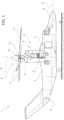
Figure 1 is a side view of a tilt-rotor aircraft comprising a pair of rotors realised according to the dictates of a first embodiment of the present invention and in a "helicopter" configuration; -
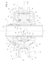
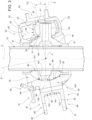
Figures 2 and3 show, on an enlarged scale, an axial section of one of the tilt-rotor aircraft joints inFigure 1 in a first and second operating position respectively; -
Figure 4 is an exploded view of the transmission joint ofFigures 2 and3 , with parts removed for clarity; -
Figure 5 is a perspective view of the transmission joint ofFigures 2 to 4 , on an enlarged scale; -
Figure 6 is a further enlarged and partially sectioned perspective view of the transmission joint ofFigure 5 , with parts removed for clarity; -
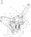
Figure 7 is a perspective view of some components of the transmission joint ofFigures 2 to 6 , with parts removed for clarity and in a first operating condition; -
Figure 8 is an exploded view of the transmission joint ofFigures 2 to 7 , with parts removed for clarity and in a second operating condition; -
Figure 9 is a section along line IX-IX ofFigure 8 ; -
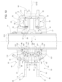
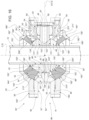
Figures 10 and11 show an axial section of a second embodiment of one of the transmission joints of the tilt-rotor aircraft inFigure 1 in a first and second operating position respectively; -
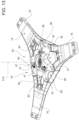
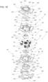
Figure 12 is an exploded view of the transmission joint ofFigures 10 and11 ; -
Figure 13 is a perspective view of the transmission joint ofFigures 10 to 12 , in an enlarged scale; -
Figure 14 is a further enlarged and partially sectioned perspective view of the transmission joint ofFigure 13 , with parts removed for clarity; -
Figure 15 is a perspective view of some components of the transmission joint fromFigures 10 to 14 , with parts removed for clarity; -
Figures 16 and17 show a third embodiment of one of the transmission joints of the tilt-rotor aircraft ofFigure 1 in a first and second operating position respectively; -
Figure 18 is an exploded view of the transmission joint ofFigures 16 and17 ; -
Figure 19 is a perspective view of the transmission joint ofFigures 16 to 18 , in an enlarged scale; -
Figure 20 is a further enlarged and partially sectioned perspective view of the transmission joint ofFigure 19 , with parts removed for clarity; and -
Figure 21 is a perspective view of some components of the transmission joint ofFigures 16 to 20 , with parts removed for clarity. - Referring to
Figure 1, 1 denotes an aircraft capable of hovering, in particular a tilt-rotor aircraft. - The tilt-
rotor aircraft 1 essentially comprises: - a
fuselage 2 having an axis A of longitudinal extension; - a pair of half-
wings 3 extending in a cantilever manner from respective parts opposite one another of thefuselage 2 and transversely to the axis A; and - a pair of
nacelles 4 housingrespective powerplant groups 5 and tiltable with respect to thefuselage 2 about an axis G orthogonal to the axis A. - The
fuselage 2 also comprises anose 12 arranged at the front and atail portion 13 that are opposite one another along the axis A. - The half-
wings 3 have respective directions of longitudinal extension parallel to the axis G orthogonal to the axis A. - It should be noted that the term "front", "of tail", "longitudinal", "lateral", "above" and "below" and the like used in this description refer to a normal direction of advancement of the tilt-
rotor aircraft 1 in forward flight. - In the following of the present description a
single powerplant group 5 is described, being thepowerplant groups 5 identical to each other. - The
powerplant group 5 essentially comprises: - a motor 6 provided with an output shaft rotatable about an axis B orthogonal to the axis G;
- a rotor 8; and
- a
transmission unit 11 interposed between the motor output shaft 6 and acontrol shaft 10 of the rotor 8, so as to drive thecontrol shaft 10 to rotate about an axis C. - In the case shown, the rotation axis of the motor output shaft 6 and the axis C are parallel and offset from each other.
- The tilt-
rotor aircraft 1 can be selectively arranged: - in a "helicopter" configuration (visible in
Figure 1 ), in which the axes C are orthogonal to the axis A; and - in an "airplane" configuration (not shown), in which the axes C are parallel to the axis A.
- The transition of the tilt-
rotor aircraft 1 between the "helicopter" and "airplane" configurations is achieved by tilting the rotors 8 about the axis G. - In the case shown, the rotors 8 are tilted integrally with the
nacelles 4 and with thepowerplant groups 5 about the axis G during the aforesaid transition. - The rotor 8 in turn comprises (
Figures 1 to 3 ): - the
control shaft 10 having an axis C; - a
hub 15 having an axis D and provided with a plurality, three in the case shown, ofarms 16 extending radially to the axis D (Figures 5 and6 ); - a plurality of
blades 17, three in the case shown, articulated onrelative arms 16 of thehub 15; and - a joint 20 interposed between the
control shaft 10 and thehub 15. - The joint 20 is, in the case shown, a constant velocity joint configured to transmit a torque having a main component axis C from the
control shaft 10 to thehub 5, and an aerodynamic force having a component parallel to the axis D from thehub 15 to thecontrol shaft 10 and to thefuselage 2. - The joint 20 is also an articulated joint configured to allow the oscillation of the axis D of the
hub 15 with respect to the axis C of thecontrol shaft 10. - As visible in the
Figures 2 and3 , thecontrol shaft 10 and thehub 15 have respective axes E, F that are radial and orthogonal to the respective axes C, D. - The joint 20 is configured to allow the oscillation of the axis D relative the axis C - and, therefore, of the axis F about the axis E - by a variable angle α comprised between 0 degrees (
Figure 2 ) and, in the case shown, +/-12 degrees (Figure 3 ). - In particular, the joint 20 is also configured to allow the oscillation of the axis D with respect to the axis C about a point P defined by the intersection of the axes C, D.
- The joint 20 comprises, in turn (
Figures 2 to 7 ): - an
element 45 defining acylindrical seat 46 of axis C coupled to thecontrol shaft 10 by a pair of axially staggeredgrooved profiles 47 parallel to the axis C; and - an
assembly 50 connected to thehub 15 at a fixed angle relative to the axis D. - The joint 20 further comprises connecting
means 60 for connecting theelement 45 to theassembly 50, and configured to allow transmitting the torque having a main component along the axis C and the force having a main component along the axis D between theelement 45 and theassembly 50. - Advantageously, the connecting
means 60 comprise, in turn: - a plurality of
rollers 54, three in the case shown, carried by theelement 45 and extending along their respective longitudinal axes Z; and - a plurality of
chambers 53, three in the case shown, defined by theassembly 50 and housingrespective rollers 54; - each
chamber 53 is circumferentially delimited towards therelative roller 54 by asurface 59, which circumferentially contacts the axis C with therelative roller 54, as a result of the rotation of theelement 45 about the axis C itself; - the
element 45 andassembly 50 are coupled together so that the axes B, C can be tilted by the angle α (Figure 2 ). - In greater detail, the
element 45 comprises: - a main
tubular body 48 defining theseat 46; - a plurality of
arms 56, three in the case shown, projecting cantilevered from themain body 48 in a direction radially external to the axis C, and extending along respective axes E radial to the axis C; and - a plurality of pairs of dampening elements 49 (
Figure 4 ), in the case shown three pairs, each associated with arespective arm 56. - Specifically, the
arms 56 are associated with respective axes E and therollers 54 extend along respective axes Z. - The
element 45 further comprises a plurality ofjunctions 44 mounted coaxially onrespective arms 56, and interposed between therespective arms 56 and therespective rollers 54 radially to the relative axis E. - In particular, each
junction 44 allows the rotation of therelative roller 54 about the relative axis E and the tilt of the axis Z of therelative roller 54 with respect to the relative axis E (Figure 3 ). - The dampening
elements 49 of each pair are circumferentially interposed with respect to the axis D between the correspondingroller 54 and thecorresponding chamber 53. - The
main body 48 comprises, in turn: - a pair of
portions 57 of axial ends opposite to each other and shaped as respective cylinders of axis C; and - a
portion 58 axially interposed between theportions 57 and shaped like a spherical crown. - The
portion 58 is delimited, in a position radially external to the axis C, by asurface 55 radially opposite to theseat 46. - The
arms 56 protrude radially from thesurface 55 on the side radially opposite the axis C. - The
surface 55 is spherical, symmetrical with respect to the axis C and with a centre P. - In particular, the
portion 58 has a larger axial dimension thanportions 57 and has a maximum diameter that is larger than the diameters of theportions 57. - The
rollers 54 and therelative arms 56 are angularly spaced about the axis C. - More precisely, the
rollers 54 and therelative arms 56 are angularly equally-spaced about the axis C. - In short, each
roller 54 has a tubular shape along the relative axis E. - Each
roller 54 comprises, in turn: - a pair of
faces 61 of axial ends opposite to each other with respect to the relative axis Z and orthogonal to the relative axis Z; and - a
circumferential surface 62, radially external to the relative axis Z, radially opposite to therelative junction 44 and axially interposed between the faces 61. - The dampening
elements 49 are, in greater detail, circumferentially interposed between respective portions of thesurface 62 and therelative chamber 53. - Each dampening
element 49 comprises, in particular (Figure 4 ): - a
concave wall 71 partially housing therelative roller 54 and radially internal with respect to the axis E; - a
wall 72 opposite thewall 71 and radially external to the axis E; and - a pair of
walls walls relative roller 54. - The
wall 71 of each dampeningelement 49 defines a rolling track for the correspondingroller 54. - The
wall 71 is made of steel. - Each dampening
element 49 further comprises a plurality offoils 75 overlapping each other and interposed between thewalls - The foils 75 are formed by alternating layers of elastomeric materials and steel.
- The
assembly 50 comprises aspherical surface 65 with the centre at point P sliding on thesurface 55 to form a spherical hinge with the centre at point P between thehub 15 and the control shaft 10 (Figure 2 ). - The
surface 55 comprises a portion 67 axially interposed between respective sections of thesurface 55 along the axis D, so as to allow transmitting a force parallel to the axis D in both directions from theassembly 50 integral with theblades 17 to theelement 45 integral with thecontrol shaft 10. - The
assembly 50 further defines thechambers 53 delimited byrespective surfaces 59 and housing the correspondingrollers 54. - Each
surface 59 houses therelative roller 54 with an axial clearance, a radial clearance and substantially no circumferential clearance, with reference to the axis D. - Each
chamber 53 is filled with a lubricating grease. - Referring to
Figure 2 , eachchamber 53 is axially closed in the radially internal position and closed in the radially external position, relative to the axis D. - The
chambers 53 are angularly equally-spaced about the axis D. - The
assembly 50 comprises, in particular (Figure 4 ), a pair ofcrankcases element 45. - In greater detail, each
crankcase - Each
crankcase - a
respective portion 81; 82 of axial end; - a
respective portion 83; 84 of axial end opposite to the correspondingportion 81; 82; and - a
respective flange portions - The
portions - The
portion 81 further comprises a plurality ofseats 89, three in the case shown, extending radially to the axis E and arranged, in the case shown, equally-spaced about the axis E. - The
seats 89 are arranged at respective planes radial to the axis E. - The
portions appendages 100, three in the case shown, angularly equally-spaced between each other about the axis D. - The
appendages 100 protrude axially cantilevered from therespective flange respective portion - Each
appendage 100 comprises, in particular (Figures 2 to 4 ) : - a radially
internal wall 101, concave and shaped as a portion of a spherical surface with a centre P; - a plane, radially
external wall 102 lying on a respective plane orthogonal to the axis E; and - a
wall 103 lying in a plane orthogonal to the axis D, axially opposite therelevant flange walls - Each
flange - a plurality of
attachment elements - a plurality of
walls respective attachment elements - The
walls - Each
wall relative portion relative portion - The
walls roller 54. - The
walls attachment elements relative portion - Referring to the axis D, the
wall 92 is axially open towards theportion 82, axially closed towards theportion 81 and circumferentially closed. - Referring to
Figure 4 , thewall 92 is radially open both towards the axis E and towards the side opposite the axis E. - The
wall 93 is radially closed in the direction opposite the axis E and open in the direction of the axis E. - The
walls - The
wall 92 extends towards thewall 93 beyond the axis E. - Each
crankcase related surface surface 55 of theelement 50. - The
surfaces - The
surfaces surface 65 of theassembly 50. - The
surfaces respective walls 101 of the correspondingappendages 100 and the radially inner walls of theflanges - The portion 67 of the
surface 55 is axially interposed, at least partially, between thesurfaces assembly 50 integral with theblades 17 to theelement 45 integral with thecontrol shaft 10. - The
attachment elements portions crankcases assembly 50. - The
portions portions - Each
wall 92 of thecrankcase 51 is axially overlapping on arelative wall 93 of thecrankcase 52, so as to form arespective surface 59 of acorresponding chamber 53. - The joint 20 further comprises a plurality of stop elements 95 (
Figures 2 to 9 ) carried by thecrankcase 51 and configured to abut against a fixed structure relative to thecontrol shaft 10, so as to limit the value of the angle α to a maximum threshold value. - Each
stop element 95 comprises, in particular: - a
pin 96 fixed within therespective seat 89; and - an
abutment element 97 integral with thepin 96 and adapted to abut against the fixed structure when the angle α reaches the maximum threshold value. - Each
stop element 95 is selectively available in: - a first position (shown in
Figures 2 to 7 ) wherein theabutment elements 97 define a first angle with the axis D; and - a second position (shown in
Figures 8 and9 ) wherein theabutment elements 97 define a second angle with the axis D lower than the first angle. - The
stop elements 95 are arranged in the respective first positions when the tilt-rotor aircraft 1 is in flight. - The
stop elements 95 are arranged in the respective second positions when the tilt-rotor aircraft 1 is on the ground. - In use, the tilt-
rotor aircraft 1 lands and takes off in the "helicopter" configuration and advances in the "airplane" configuration. - In both configurations, the motors 6 drive the rotors 8 to rotate about the respective axes D.
- More specifically, each motor 6 drives the
relative control shaft 10 to rotate about the relative axis C. - The
control shaft 10 drives thehub 15 andblades 17 to rotate about the axis D by means of the joint 20. - The
blades 17 thus generate an aerodynamic force having a main component parallel to the axis D. - In the hovering or low-speed "helicopter" configuration, the rotors 8 are arranged with the respective axes D orthogonal to the axis A (
Figure 1 ). - The aerodynamic force generated by the
blades 17 of each rotor 8 supports the tilt-rotor aircraft 1 in flight. - In the "aeroplane" configuration, not shown, the rotors 8 are arranged with the respective axes D parallel to the axis A. The aerodynamic force generated by the
blades 17 of the rotors 8 provides the thrust required to move the tilt-rotor aircraft 1 forward and the lift required to support the tilt-rotor aircraft 1 is mostly provided by the half-wings 3. - In greater detail, the joint 20 is homokinetic, i.e. the ratio between the rotation speeds of the
control shaft 10 about the axis C and of thehub 15 about the axis D is constant, equal to one in the case shown, for each angular position of thecontrol shaft 10 or of thehub 15 relative to the respective axes C, D. - The joint 20 performs the following functions:
- allows the oscillation of the axis D relative to the axis C so that the oscillation of the axis E relative to the axis F is equal to the angle α between 0 degrees (
Figure 2 ) and, in the case shown, 12 degrees (Figure 3 ). This oscillation is due to the fact that the aerodynamic forces acting on theblades 17 are hardly ever perfectly symmetrical, for example due to a gust of wind or from the variation of the cyclic pitch of theblades 17 themselves. These non-symmetrical forces are also generated during the transition of the tilt-rotor aircraft 1 between the "airplane" and "helicopter" configurations or due to the gyroscopic forces generated in the event of storms acting on theblades 17; - enables the transmission of the aerodynamic force parallel to the axis D from the
blades 17 to thefuselage 2; and - enables the transmission of the driving torque of axis C from the
control shaft 10 to theblades 17. - In greater detail, the
control shaft 10 drives theelement 45 to rotate and, thus, therollers 54 about the axis C. - The rotation of the
rollers 54 about the axis C determines, due to the circumferential contact at the axes B, C between dampeningelements 49 andrespective surfaces 59 of the correspondingchambers 53, the rotation of theassembly 50 about the axis D. - The dampening
elements 49 slightly dampen the torsional oscillations of thecontrol shaft 10,hub 15,element 45 andassembly 50. - The
assembly 50 drives, in turn, thehub 15 and thus theblades 17 to rotate about the axis D - Thus, the torque with the main component along the axis C is transmitted from the
control shaft 10 to theblades 17. - The aerodynamic force generated by the
blades 17 is transmitted from theassembly 50 to thecontrol shaft 10 and, therefore, to thefuselage 2, by the action of thesurface 65 of theassembly 50 on thesurface 55 of theelement 45. - At the same time, the
surface 65 of theassembly 50 rolls without creeping on thesurface 55 of theelement 45 about the centre P, allowing the tilt of the axis D of thehub 15 with respect to the axis C of thecontrol shaft 10 by the angle α about the centre P. - During this tilt, the axes Z of the
rollers 54 tilt by the angle α relative to the axes E of the arms 56 (Figure 3 ). - This tilt is stopped when the angle α reaches the maximum threshold value, as the
stop elements 95 come into contact against the fixed structure integral with thecontrol shaft 10. - Referring to
Figures 10 to 15 , 20' denotes a joint according to a second embodiment of the present invention. - The joint 20' is similar to the joint 20 and will be described hereinafter only for what differs from the latter; equal or equivalent parts of the
joints 20, 20' will be marked, where possible, with the same reference numbers. - The connecting means 60' of the joint 20' differ from the connecting means 60' of the joint 20' in that:
- the element 45' comprises a plurality of grooves 132', eighteen in the embodiment shown, formed in the
surface 55 and in thesurfaces respective balls 135' free to roll within the respective grooves 132' maintaining contact with thesurface 55 of the element 45' and therespective surfaces assembly 50; and - the
surfaces respective crankcase surface 55. - The grooves 132' extend along the respective meridians of the
surface 55 and surfaces 87, 88, and have, each, respective ends 133', 134' opposite to each other. - The grooves 132' each have a length along their respective meridian and a width measured circumferentially to the axis C.
- The length of the grooves 132' is greater than the width of the grooves 132' themselves.
- The length of the grooves 132' corresponds to an angle at the centre P equal to twice the maximum value of the angle α.
- The width of the grooves 132' corresponds to the diameter of the
balls 135'. - The
surfaces balls 135'. - The
balls 135' are free to rotate about their respective axes H' and to roll on thesurfaces surface 55 within the respective grooves 132' about the point P and between the aforesaid ends 133'. - In greater detail, the joint 20' comprises a plurality of groups 130', 131', six in the case shown, each formed by a plurality, three in the case shown, of grooves 132' circumferentially equally-spaced about the axis C.
- Each groove 132' of the group 130' has a length along the same meridian of a corresponding groove 132' of the group 131'.
- Each groove 132' has a pair of end edges 136', 137' circumferentially opposed to each other at axes C, D and interposed between the ends 133', 134'.
- The groups 130' (131') are angularly equally-spaced about the axis C and circumferentially interposed between respective rollers 34.
- Each group 130' and the relative grooves 132' are arranged symmetrically with respect to a corresponding group 131' and the relative grooves 132', with reference to an equatorial median plane of the element 45' parallel to the axis E and orthogonal to the axis C.
- The
balls 135' of the groups 130' roll without creeping on thesurfaces - Referring to a first direction - oriented from the top downwards in
Figures 10 and11 - of travel along the axis D, the contact points Q of theballs 135' of the groups 130' are arranged upstream - at the top inFigures 10 and11 - of the contact points R. - Consequently, the
balls 135' of the groups 130' transmit a force having a component along the axis D and oriented along the first direction from thehub 15 and theassembly 50 to the element 45' and thecontrol shaft 10. - The
balls 135' of the groups 131' roll without creeping on thesurfaces - With reference to a second direction opposite to the first direction - oriented from the bottom upwards in
Figures 10 and11 - of travel of the axis D, the contact points S of theballs 135' of the groups 131' are arranged upstream - at the bottom inFigures 10 and11 - of the contact points T. - Consequently, the
balls 135' of the groups 131' transmit a force having a component along the axis D and oriented along the second direction from thehub 15 and theassembly 50 to the element 45' and thecontrol shaft 10. - The joint 20' further comprises a plurality, six in the case shown, of cages 140' adapted to guide the
balls 135' of a respective group 130', 131'. - Referring to
Figure 12 , each cage 140' has an annular shape and is delimited by: - a pair of edges 141' opposite to each other, arranged circumferentially to the axis C and arranged at a distance corresponding to the radius of the
balls 135'; and - a pair of edges 142' interposed between the edges 141'.
- The operation of the joint 20' is described hereinafter only for what differs from the operation of the joint 20.
- In particular, the joint 20' transmits the force having a main component along the axis D from the
blades 17 to thecontrol shaft 10 by theballs 135' rolling without creeping on thesurfaces assembly 50 and on thesurface 55 of the element 45'. - More precisely, the force having a main component along the axis D and directed along the first direction - oriented from the top downwards in
Figures 10 and11 - is transmitted from thesurface 87 to theballs 135' of the groups 130' and from the latter to thesurface 55 of the element 45'. - The force having a main component along the axis D and directed along the second direction - oriented from the bottom upwards in
Figures 10 and11 - is transmitted from thesurface 88 to theballs 135' of the groups 131' and from the latter to thesurface 55 of the element 45'. - The joint 20' also allows the tilt of the
hub 15 and, therefore, of theassembly 50 with respect to thecontrol shaft 10 and, therefore, to the element 45', by means of the rolling without creeping of theballs 135' about the respective axes H' on thesurfaces assembly 50 and on thesurface 55 of the element 45' within the respective grooves 132' and about the point P. - In particular, when the axis D of the
hub 15 tilts to one side of the axis C of thecontrol shaft 10, theballs 135' move closer to the respective ends 133' of the grooves 132'. - Otherwise, when the axis D of the
hub 15 tilts to the other side of the axis C, theballs 135' move closer to the respective ends 134' of the respective grooves 132'. - Referring to
Figures 16 to 21 , 20" denotes a joint according to a third embodiment of the present invention. - The joint 20" is similar to the joint 20 and will be described hereinafter only for what differs from the latter; equal or equivalent parts of the
joints - The joint 20" differs from the joint 20 in that the
crankcases 51", 52'' do not include therespective portions - The joint 20" also differs from the joint 20" in that it comprises a pair of tubular bodies 150'' between which the
element 45" is axially interposed along the axis C. - The bodies 150'' are housed within the
assembly 50" and are shaped like respective hollow spherical caps. - The bodies 150'' each have:
- an
axial end surface 151" arranged in abutment against theelement 45" and delimited by a circular edge 152'' radially external to the axis C; - an
edge 156" of axial end opposite to the edge 152'', circular and radially internal to the axis C; and - a side surface 160'' extending axially between the
edges 152", 156'', radially external to the axes C, D and having decreasing diameters proceeding from the edge 152''' towards the edge 156'' parallel to the axis C. - The surfaces 160'' define respective axial extensions of the
surface 55 and are designed as respective portions of spherical surfaces with a centre P. - The
bodies 150" also define respectivecylindrical seats 159" of axis C, which are contiguous to theseat 46 and defining respective axial extensions of theseat 46. - In particular, the diameter of the
edge 152" is larger than the diameter of theedge 156". - The diameters of the
edges 152" are equal to each other and the diameters of theedges 156" are equal to each other. - The joint 20" also differs from the joint 20 in that the
surfaces crankcases element 45" and from thebodies 150". - The joint 20" also differs from the joint 20 in that it comprises:
- a pair of
lids 180" arranged on axially opposite sides of theelement 45" and connected to thehub 15 so as to be rotatable integrally with thehub 15 about the axis D; and - a pair of
elastomeric elements 184" axially interposed, each, between arelative lid 180" and arelative body 150". - In greater detail, each
lid 180" is tubular with respect to the axis D and is connected to arespective crankcase 51", 52". - The
elastomeric elements 184" are each interposed between a relative lid 180'' and arelative body 150". - Each lid 180'' further comprises:
- a flange 181'' defining a
seat 182; and - a plurality, three in the case shown, of
arms 183" projecting radially cantilevered from the flange 181'' in the opposite direction to the axis D and connected torespective attachment elements relevant crankcase - The flange 181'' comprises a
circular end 185" and an end 186'' axially opposite to the end 185'' and from which thearms 183" protrude in a cantilevered way. - The
end 186" of eachflange 181" is formed as a plurality of arcs of circumference with a centre on the axis D alternating with respective arms 183'', along a direction circumferential to the axis D. - Each
flange 181" has radial dimensions increasing with respect to the axis D, proceeding from the respective end 185'' to therespective end 186". - The end 185'' is circular and with a diameter smaller than the
end 186". - Each
elastomeric element 184" comprises, in turn: - a circular edge 190'' with axial end;
- an
edge 191" axially opposite to the edge 190''; and - a side surface 192'' radially external and axially delimited by the
edges 190", 191". - The
edge 191" comprises, in turn (Figure 18 ): - a plurality, three in the case shown, of arcs of circumference 205'' with the centre on the axis D;
- a plurality, three in the case shown, of linking
sections 206" circumferentially alternating to the arcs 205'', having the concavity facing opposite theedge 190", and extending symmetrically at axial distances firstly increasing and then decreasing from thearcs 205" proceeding in a circumferential direction to the axis D. - The side surface 192'' is shaped as a portion of a spherical surface with a centre P and comprises, in the case shown in
Figure 18 : - a plurality, three in the case shown, of main portions 210'' (only one of which is shown in
Figure 18 ) and extending, each, between the edge 190'' and a relative arc 205''; and - a plurality, three in the case shown, of linking
portions 211" (only one of which is shown inFigure 18 ) circumferentially alternating with respective main portions 210'' and extending, each, between the edge 190'' and arelated section 206". - Each elastomeric element 184'' further comprises:
- a
circular edge 193", radially internal to theedges 190", 191"; - an edge axially opposite 194'' and radially external to the
edge 193", and radially internal to the edge 191''; and - a side surface 195'' radially internal and axially delimited by the
edges 193", 194''. - The edge 194'' comprises, in turn:
- a plurality, three in the case shown, of arcs of circumference 215'' with the centre on the axis D;
- a plurality, three in the case shown, of linking sections 216'' circumferentially alternating to the arcs 215'', having the concavity facing opposite the
edge 190", and extending symmetrically at axial distances firstly increasing and then decreasing from thearcs 215" proceeding in a circumferential direction to the axis D. - The side surface 195'' is shaped as a portion of a spherical surface with a centre P and comprises, in the case shown in
Figure 18 : - a plurality, three in the case shown, of
main portions 220" (only one of which is shown inFigure 18 ) and extending, each, between the edge 193'' and a relative arc 215''; and - a plurality, three in the case shown, of linking
portions 221" (only one of which is shown inFigure 18 ) circumferentially alternating with respectivemain portions 220" and extending, each, between theedge 193" and arelated section 216". - The
main portions 210", 211''; the linkingportions 220", 221"; the arcs 205'', 215"; and thesections 206", 216" are arranged circumferentially to the axes C, D, when theelastomeric element 184" is undeformed. - Finally, each elastomeric element 184'' finally comprises:
- an axial end surface 200'', which extends between the edges 190'', 193"; and
- an axial end surface 201'' opposite the surface 200'' and extending between the edges 191'', 194''.
- In greater detail, the
elastomeric elements 184" have theirrespective edges 194" facing each other and interposed axially between theedges 193". - The surface 192'' of each
elastomeric element 184" is pressed against the surface 182'' of the respective lid 180''. - The
surface 195" of eachelastomeric element 184" is pressed against the surface 160'' of the corresponding body 150''. - The surfaces 195'' comprise, in particular, respective portions interposed axially between respective portions of the surfaces 192'', so as to allow transmitting a force having a main component parallel to the axis D in both directions from the
hub 15 to thecontrol shaft 10. - The joint 20" also differs from the joint 20 in that it does not include the
stop elements 95. - The operation of the joint 20" is described hereinafter only for what differs from the operation of the joint 20.
- In particular, the joint 20" transmits the force having a main component along the axis D from the
blades 17 to thecontrol shaft 10 via the elastomeric elements 184'' having respective surfaces 192'' angularly integral with thehub 15 and theblades 17 about the axis D and respective surfaces 195'' angularly integral with thecontrol shaft 10 about the axis C. - The
elastomeric elements 184" also transmit a residual portion of the driving torque with the main component along the axis C. - The elastomeric elements 184'' further allow, by means of elastic deformation, the tilt of the
hub 15 and, therefore, of theassembly 50 with respect to thecontrol shaft 10 and, therefore, to theelement 45, by means of the relative elastic deformation between a substantially torsionally undeformed position assumed when the axes C, D match with each other (Figure 16 ) and a torsionally deformed position assumed when the axes C, D are tilted with respect to each other (Figure 17 ). - After examining the transmission joint 20, 20', 20'' made according to the present invention the advantages it allows to be obtained are evident.
- In particular, the
joints control shaft 10 to thehub 15 by the action of therollers 54 on thesurfaces 59 of therespective chambers 53 in a direction circumferential to the axis C. By contrast, the aerodynamic force is transmitted from theblades 17 and thehub 15 to thecontrol shaft 10 by coupling thesurfaces 65 of theassembly 50 and thesurface 55 of the element 45 - or between theballs 135' and thesurfaces 55; 87, 88 in the joint 20' or between the elastomeric element 184'' andelement 45 and cover 180" -. - As a result, the transmission paths of the torque of axis C and of the force of axis D are independent and distinct from each other, unlike the known solutions described in the introductory part of this description.
- The joint 20, 20', 20" is thus more balanced, and is cheaper and lighter than the above-mentioned known solution.
- The
crankcases assembly 50 are easily disassembled to allow access to the joint 20; 20'; 20". - The
chambers 53 are independent of each other. It is thereby prevented any contamination of the lubricating grease contained in achamber 53 and/or any failure of therespective roller 54 from impairing the functionality of theother chambers 53 andrespective rollers 54. - The
rollers 54 and dampeningelements 49 are easily detachable and replaceable in the event of wear, without requiring any replacement of theelement 45. - The
stop elements 95 limit the value of the angle α to the expected threshold value depending on the operating configuration of the tilt-rotor aircraft 1. - The
stop elements 95 are arranged in the respective first positions when the tilt-rotor aircraft 1 is in flight. - The
stop elements 95 are arranged in the respective second positions when the tilt-rotor aircraft 1 is on the ground. - Due to the fact that the transmission joints 20, 20' do not have any elastomeric material components intended to transmit torque and force, it is not necessary to set up visual inspection procedures that are particularly time-consuming in terms of interruption of the operation of the tilt-
rotor aircraft 1. - The resulting joint 20, 20', 20" can have any number of
arms 56 so that it can be easily coupled tohubs 15 provided with any number ofblades 17. - It is clear that modifications and variations can be made to the
joints
Claims (15)
- Transmission joint (20; 20'; 20") of the articulated type for connecting a drive shaft (10) to a hub (15) of a rotor (8, 8', 8"), comprising:- a first element (45, 45', 45") rotatable about a first axis (C) and connectable in an angularly fixed manner to said drive shaft (10) about said first axis (C) ;- a second element (50, 51, 52; 50", 51", 52") rotatable about a second axis (D) and connectable in an angularly fixed manner to said hub (15); and- connecting means (60, 60', 60") adapted to connect said first element (45, 45', 45") and said second element (50, 51, 52; 50", 51", 52") and configured to allow, in use, the transmission between said first and second elements (45, 45', 45"; 50, 50"; 51, 52, 51", 52") of a torque having a main component along said first axis (C) and of a force having a main component along said second axis (D);said first axis (C) and second axis (D) being incident at a first point (P);said connecting means (60, 60', 60") comprising, in turn:- at least one roller (54) carried by said first element (45, 45', 45") and extending along a further axis (Z) tiltable with respect to said first axis (C); and- at least one chamber (53) defined at least partially by said second element (50, 51, 52; 50", 51'', 52") and housing at least partially said roller (54);said chamber (53) being delimited towards said roller (54) by a first surface (59) adapted to come into contact at least indirectly, in use, with the roller (54) circumferentially to said first axis (C), after the rotation of said first element (45, 45', 45") about said first axis (C);said first and second elements (45, 45', 45"; 50, 51, 52; 50", 51", 52'') being coupled to each other so as to allow, in use, a tilt of an angle (α) between said first and second axes (C, D);characterised in that it comprises dampening means (49) circumferentially interposed with respect to said first axis (C) between said roller (54) and said first surface (59) of said chamber (53).
- Transmission joint according to Claim 1, characterised in that said chamber (53) defines a clearance between said first surface (59) and said roller (54) parallel to said first axis (C).
- Transmission joint according to Claim 1 or 2, characterised in that said first element (45, 45', 45") comprises a plurality of said rollers (54) circumferentially spaced about said first axis (C), and said second element (50, 51, 52; 50", 51", 52'') comprises a plurality of said chambers (53) circumferentially spaced about said first axis (C) and associated with respective said rollers (54).
- Transmission joint according to Claim 3, characterised in that said first element (45, 45', 45") comprises, in turn:- a main body (48) defining a second surface (55) at least partially spherical with the centre at said first point (P); and- a plurality of arms (56) projecting cantilevered from said main body (48) radially to said first axis (C) and defining respective said chambers (53) for corresponding said rollers (54).
- Transmission joint according to any one of the preceding Claims, characterised in that it comprises two said second elements (51, 52; 51", 52'') each defining a relative portion (92; 93) of said chamber (53);
said second elements (51, 52; 51", 52'') being releasably connected to each other, connected to said hub (15) and superimposed on each other parallel to said first axis (C). - Joint according to Claim 4 or 5, characterised in that said arms (56) extend along respective third axes (E) radial to said first axis (C), and in that said first element (45) comprises a plurality of junctions (44) carried by respective arms (56) and on which respective rollers (54) are mounted; said junctions (44) enabling the rotation of respective said rollers (54) about said third axis (E) and the tilt of fourth axes (Z) of said rollers (54) with respect to respective said third axes (E) .
- Joint according to any one of the preceding Claims, characterised in that said second element (51, 52) comprises a plurality of stop elements (95) configured to abut, in use, against a structure angularly integral with said first element (45, 45'), so as to limit said tilt between said first and second axes (C, D).
- Joint according to Claim 7, characterised in that said stop elements (95) are selectively movable between:- a first position wherein the respective abutment elements (97) define a first angle with said second axis (D); and- a second position wherein said respective abutment elements (97) define a second, lower angle of said first angle with said second axis (D).
- Joint according to Claim 4 or any one of Claims 5 to 8, when dependent on Claim 4, characterised in that said first element (45) is housed within said second element (50);said connecting means (60) comprising, in turn, said second surface (55) and a third spherical surface (65; 87, 88) defined by said second element (50; 51, 52);said third spherical surface (65; 87, 88) contacting said second surface (55) and being concentric thereto at said first point (P), so as to allow the relative tilt between said first and second axes (C, D) about said first point (P).
- Joint according to Claim 9, characterised in that one (55) between said second and third surfaces (55; 65; 87, 88) has at least one portion (67) interposed axially parallel to said second axis (D) between a pair of second portions (87, 88) defined by the other one (65; 87, 88) of said second and third surfaces (55; 65; 87, 88), so as to enable the transmission of a force directed parallel to said second axis (D) in both directions from said second element (50; 51, 52) to said first element (45) .
- Joint according to any one of Claims 1 to 8, characterised in that said connecting means (60') comprise, in turn, at least:- a first rolling body (135') contacting said second surface (55) at a second point (R) and said third surface (65; 87, 88) at a third point (Q), so as to roll about said first point (P) while rotating about a respective fourth axis (H');- a second rolling body (135') contacting said second surface (55) at a fourth point (T) and said third surface (65; 87, 88) at a fifth point (S), so as to roll about said first point (P) while rotating about a respective further fourth axis (H');said second and fourth points (R, T) being interposed between said third and fifth points (Q, S) parallel to said second axis (D), so as to allow the transmission of a force directed parallel to said second axis (D) in both directions from said second element (50; 51, 52) to said first element (45).
- Joint according to Claim 11, characterised in that at least one of said second surface (55) and said third surface (87, 88) comprises a plurality of grooves (132') elongated along respective meridians and spaced circumferentially to said first axis (C);
said first and second rolling bodies (135') engaging said grooves (132'). - Joint according to any one of the foregoing claims, characterised in that said connecting means (60") comprise, in turn, at least one elastomeric element (184") interposed, at least indirectly, between said first element (45) and said second element (55);
each said elastomeric element (184") comprising, in turn:- a fourth surface (192") at least partially spherical with reference to an undeformed configuration of said elastomeric element (184''), having the centre at said first point (P) and cooperating, directly or indirectly, with said second element (50"; 51", 52''); and- a fifth surface (195'') radially opposite said fourth surface (192"), at least partially spherical relative to said undeformed configuration of said elastomeric element (184''), having the centre at said first point (P) and cooperating, directly or indirectly, with said first element (45). - Joint according to Claim 13, characterised in that it comprises a pair of said elastomeric elements (184") axially spaced apart from each other and between which said point (C) is axially interposed;said elastomeric elements (184") comprising respective fourth surfaces (192'') and respective fifth surfaces (195");said fifth surfaces (195") being interposed at least partially between at least respective portions of said fourth surfaces (192"), proceeding along said second axis (D), so as to allow the transmission of a force directed parallel to said second axis (D) in both directions from said second element (50; 51, 52) to said first element (45).
- A tilt-rotor aircraft (1) characterized in that it comprises:- a fuselage (2) extending along a fifth axis (A);- a pair of half-wings (3) extending from respective side bands opposite to each other of said fuselage (2);- a pair of rotors (8, 8', 8") associated with said half-wings (3) and tilted about a sixth axis (G) orthogonal to said first and fifth axes (C, A) between:a first position wherein said second axes (D) are parallel to said fifth axis (A), which position is reached when said tilt-rotor aircraft (1) is, in use, in an airplane configuration; anda second position wherein said second axes (D) are orthogonal to said fifth axis (A), which position is reached when said tilt-rotor aircraft (1) is, in use, in a helicopter configuration;each said rotor (8, 8', 8") comprising, in turn:a relative said drive shaft (10);a relative said hub (15) on which a plurality of respective blades (16) are articulated; anda relative articulated transmission joint (20, 20', 20") according to any one of the preceding Claims.
Priority Applications (4)
| Application Number | Priority Date | Filing Date | Title |
|---|---|---|---|
| EP23216241.2A EP4470913B1 (en) | 2023-05-23 | 2023-05-23 | Transmission joint for a rotor comprising a plurality of blades |
| KR1020257042933A KR20260015893A (en) | 2023-05-23 | 2024-05-23 | Power joint for a rotor comprising multiple blades |
| CN202480032070.7A CN121100093A (en) | 2023-05-23 | 2024-05-23 | Drive joint for a rotor comprising a plurality of blades |
| PCT/IB2024/055033 WO2024241270A1 (en) | 2023-05-23 | 2024-05-23 | Transmission joint for a rotor comprising a plurality of blades |
Applications Claiming Priority (2)
| Application Number | Priority Date | Filing Date | Title |
|---|---|---|---|
| EP23174771.8A EP4467450A1 (en) | 2023-05-23 | 2023-05-23 | Transmission joint for a rotor comprising a plurality of blades |
| EP23216241.2A EP4470913B1 (en) | 2023-05-23 | 2023-05-23 | Transmission joint for a rotor comprising a plurality of blades |
Related Parent Applications (2)
| Application Number | Title | Priority Date | Filing Date |
|---|---|---|---|
| EP23174771.8A Division EP4467450A1 (en) | 2023-05-23 | 2023-05-23 | Transmission joint for a rotor comprising a plurality of blades |
| EP23174771.8A Division-Into EP4467450A1 (en) | 2023-05-23 | 2023-05-23 | Transmission joint for a rotor comprising a plurality of blades |
Publications (2)
| Publication Number | Publication Date |
|---|---|
| EP4470913A1 true EP4470913A1 (en) | 2024-12-04 |
| EP4470913B1 EP4470913B1 (en) | 2026-02-25 |
Family
ID=87196346
Family Applications (5)
| Application Number | Title | Priority Date | Filing Date |
|---|---|---|---|
| EP23216250.3A Pending EP4470914A1 (en) | 2023-05-23 | 2023-05-23 | Transmission joint for a rotor comprising a plurality of blades |
| EP23216332.9A Pending EP4470916A1 (en) | 2023-05-23 | 2023-05-23 | Transmission joint for a rotor comprising a plurality of blades |
| EP23216257.8A Pending EP4470915A1 (en) | 2023-05-23 | 2023-05-23 | Transmission joint for a rotor comprising a plurality of blades |
| EP23216241.2A Active EP4470913B1 (en) | 2023-05-23 | 2023-05-23 | Transmission joint for a rotor comprising a plurality of blades |
| EP23174771.8A Pending EP4467450A1 (en) | 2023-05-23 | 2023-05-23 | Transmission joint for a rotor comprising a plurality of blades |
Family Applications Before (3)
| Application Number | Title | Priority Date | Filing Date |
|---|---|---|---|
| EP23216250.3A Pending EP4470914A1 (en) | 2023-05-23 | 2023-05-23 | Transmission joint for a rotor comprising a plurality of blades |
| EP23216332.9A Pending EP4470916A1 (en) | 2023-05-23 | 2023-05-23 | Transmission joint for a rotor comprising a plurality of blades |
| EP23216257.8A Pending EP4470915A1 (en) | 2023-05-23 | 2023-05-23 | Transmission joint for a rotor comprising a plurality of blades |
Family Applications After (1)
| Application Number | Title | Priority Date | Filing Date |
|---|---|---|---|
| EP23174771.8A Pending EP4467450A1 (en) | 2023-05-23 | 2023-05-23 | Transmission joint for a rotor comprising a plurality of blades |
Country Status (3)
| Country | Link |
|---|---|
| EP (5) | EP4470914A1 (en) |
| KR (1) | KR20260015893A (en) |
| CN (1) | CN121100093A (en) |
Citations (5)
| Publication number | Priority date | Publication date | Assignee | Title |
|---|---|---|---|---|
| US4477224A (en) | 1981-09-18 | 1984-10-16 | Westland Plc | Helicopter rotor |
| US4804352A (en) | 1987-01-30 | 1989-02-14 | Lord Corporation | Link-type rotary coupling |
| US6296444B1 (en) | 1999-10-01 | 2001-10-02 | Bell Helicopter Textron Inc. | Prop rotor hub |
| WO2010128378A2 (en) | 2009-05-06 | 2010-11-11 | K4A S.R.L. | Constant velocity joint for helicopter rotors |
| CN101973399A (en) | 2010-09-30 | 2011-02-16 | 南京航空航天大学 | Constant-speed universal hinged propeller hub for tilt-rotor aircraft |
Family Cites Families (1)
| Publication number | Priority date | Publication date | Assignee | Title |
|---|---|---|---|---|
| US6951421B2 (en) | 2003-02-14 | 2005-10-04 | Illinois Tool Works Inc. | Reclosable packaging having slider-operated string zipper |
-
2023
- 2023-05-23 EP EP23216250.3A patent/EP4470914A1/en active Pending
- 2023-05-23 EP EP23216332.9A patent/EP4470916A1/en active Pending
- 2023-05-23 EP EP23216257.8A patent/EP4470915A1/en active Pending
- 2023-05-23 EP EP23216241.2A patent/EP4470913B1/en active Active
- 2023-05-23 EP EP23174771.8A patent/EP4467450A1/en active Pending
-
2024
- 2024-05-23 CN CN202480032070.7A patent/CN121100093A/en active Pending
- 2024-05-23 KR KR1020257042933A patent/KR20260015893A/en active Pending
Patent Citations (5)
| Publication number | Priority date | Publication date | Assignee | Title |
|---|---|---|---|---|
| US4477224A (en) | 1981-09-18 | 1984-10-16 | Westland Plc | Helicopter rotor |
| US4804352A (en) | 1987-01-30 | 1989-02-14 | Lord Corporation | Link-type rotary coupling |
| US6296444B1 (en) | 1999-10-01 | 2001-10-02 | Bell Helicopter Textron Inc. | Prop rotor hub |
| WO2010128378A2 (en) | 2009-05-06 | 2010-11-11 | K4A S.R.L. | Constant velocity joint for helicopter rotors |
| CN101973399A (en) | 2010-09-30 | 2011-02-16 | 南京航空航天大学 | Constant-speed universal hinged propeller hub for tilt-rotor aircraft |
Also Published As
| Publication number | Publication date |
|---|---|
| EP4470913B1 (en) | 2026-02-25 |
| KR20260015893A (en) | 2026-02-03 |
| CN121100093A (en) | 2025-12-09 |
| EP4470914A1 (en) | 2024-12-04 |
| EP4470916A1 (en) | 2024-12-04 |
| EP4470915A1 (en) | 2024-12-04 |
| EP4467450A1 (en) | 2024-11-27 |
Similar Documents
| Publication | Publication Date | Title |
|---|---|---|
| EP2778062B1 (en) | Gimbaled tail rotor hub with elastomeric centrifugal force bearing for blade retention and pitch change articulation | |
| US7871034B2 (en) | Rotor hub systems and methods | |
| EP2223854B1 (en) | Helicopter rotor | |
| CN102458986A (en) | Constant velocity joint for helicopter rotors | |
| CN110683049B (en) | Hub device for small-sized tilt rotor aircraft | |
| JPS606840B2 (en) | rotorcraft | |
| KR20220019604A (en) | Anti-torque rotors for helicopters | |
| US5165853A (en) | Main helicopter rotor | |
| WO2024241270A1 (en) | Transmission joint for a rotor comprising a plurality of blades | |
| US12006028B2 (en) | Transmission unit of an anti-torque rotor for a helicopter | |
| EP4470913B1 (en) | Transmission joint for a rotor comprising a plurality of blades | |
| US4695227A (en) | All composite, constant speed universal joint for use in a shaft driven tiltable main rotor for a helicopter | |
| EP2894095B1 (en) | Constant velocity drive for tilt rotor assembly | |
| CN116639240A (en) | A variable pitch propeller hub structure | |
| JP2002337796A (en) | Constant speed transmission rotor for aircraft | |
| US4099892A (en) | Helicopter rotors | |
| EP2778058A1 (en) | Multilink constant velocity joint | |
| CN118323438A (en) | Universal hinged propeller hub of tiltrotor aircraft, and tiltrotor aircraft | |
| CN118424676A (en) | A universal hinged propeller hub test experimental system, combination and experimental method | |
| US4755106A (en) | Balance-bar hub for a twin blade rotor | |
| CN116981620A (en) | aircraft capable of hovering | |
| RU2746024C2 (en) | Airscrew hub with automatic swashplate | |
| CN220374747U (en) | Synchronizing device, automatic inclinator and electric aircraft | |
| RU2533374C1 (en) | Helicopter | |
| EP4484780A1 (en) | Bearing retention system |
Legal Events
| Date | Code | Title | Description |
|---|---|---|---|
| PUAI | Public reference made under article 153(3) epc to a published international application that has entered the european phase |
Free format text: ORIGINAL CODE: 0009012 |
|
| STAA | Information on the status of an ep patent application or granted ep patent |
Free format text: STATUS: REQUEST FOR EXAMINATION WAS MADE |
|
| 17P | Request for examination filed |
Effective date: 20231213 |
|
| AC | Divisional application: reference to earlier application |
Ref document number: 4467450 Country of ref document: EP Kind code of ref document: P |
|
| AK | Designated contracting states |
Kind code of ref document: A1 Designated state(s): AL AT BE BG CH CY CZ DE DK EE ES FI FR GB GR HR HU IE IS IT LI LT LU LV MC ME MK MT NL NO PL PT RO RS SE SI SK SM TR |
|
| GRAP | Despatch of communication of intention to grant a patent |
Free format text: ORIGINAL CODE: EPIDOSNIGR1 |
|
| STAA | Information on the status of an ep patent application or granted ep patent |
Free format text: STATUS: GRANT OF PATENT IS INTENDED |
|
| RIC1 | Information provided on ipc code assigned before grant |
Ipc: B64C 27/12 20060101AFI20250801BHEP Ipc: B64C 29/00 20060101ALI20250801BHEP Ipc: F16D 3/202 20060101ALI20250801BHEP Ipc: F16D 3/205 20060101ALI20250801BHEP |
|
| INTG | Intention to grant announced |
Effective date: 20250821 |
|
| P01 | Opt-out of the competence of the unified patent court (upc) registered |
Free format text: CASE NUMBER: UPC_APP_0011519_4470913/2025 Effective date: 20251029 |
|
| GRAS | Grant fee paid |
Free format text: ORIGINAL CODE: EPIDOSNIGR3 |
|
| GRAA | (expected) grant |
Free format text: ORIGINAL CODE: 0009210 |
|
| STAA | Information on the status of an ep patent application or granted ep patent |
Free format text: STATUS: THE PATENT HAS BEEN GRANTED |
|
| AC | Divisional application: reference to earlier application |
Ref document number: 4467450 Country of ref document: EP Kind code of ref document: P |
|
| AK | Designated contracting states |
Kind code of ref document: B1 Designated state(s): AL AT BE BG CH CY CZ DE DK EE ES FI FR GB GR HR HU IE IS IT LI LT LU LV MC ME MK MT NL NO PL PT RO RS SE SI SK SM TR |
|
| REG | Reference to a national code |
Ref country code: CH Ref legal event code: F10 Free format text: ST27 STATUS EVENT CODE: U-0-0-F10-F00 (AS PROVIDED BY THE NATIONAL OFFICE) Effective date: 20260225 Ref country code: GB Ref legal event code: FG4D |
|
| REG | Reference to a national code |
Ref country code: CH Ref legal event code: R17 Free format text: ST27 STATUS EVENT CODE: U-0-0-R10-R17 (AS PROVIDED BY THE NATIONAL OFFICE) Effective date: 20260227 |
|
| REG | Reference to a national code |
Ref country code: DE Ref legal event code: R096 Ref document number: 602023012578 Country of ref document: DE |
|
| REG | Reference to a national code |
Ref country code: IE Ref legal event code: FG4D |