EP4470895A1 - Straddled vehicle - Google Patents
Straddled vehicle Download PDFInfo
- Publication number
- EP4470895A1 EP4470895A1 EP23220507.0A EP23220507A EP4470895A1 EP 4470895 A1 EP4470895 A1 EP 4470895A1 EP 23220507 A EP23220507 A EP 23220507A EP 4470895 A1 EP4470895 A1 EP 4470895A1
- Authority
- EP
- European Patent Office
- Prior art keywords
- pedal
- cover
- tread portion
- pedal tread
- notch
- Prior art date
- Legal status (The legal status is an assumption and is not a legal conclusion. Google has not performed a legal analysis and makes no representation as to the accuracy of the status listed.)
- Granted
Links
Images







Classifications
-
- B—PERFORMING OPERATIONS; TRANSPORTING
- B62—LAND VEHICLES FOR TRAVELLING OTHERWISE THAN ON RAILS
- B62K—CYCLES; CYCLE FRAMES; CYCLE STEERING DEVICES; RIDER-OPERATED TERMINAL CONTROLS SPECIALLY ADAPTED FOR CYCLES; CYCLE AXLE SUSPENSIONS; CYCLE SIDECARS, FORECARS, OR THE LIKE
- B62K23/00—Rider-operated controls specially adapted for cycles, i.e. means for initiating control operations, e.g. levers, grips
- B62K23/08—Rider-operated controls specially adapted for cycles, i.e. means for initiating control operations, e.g. levers, grips foot actuated
-
- B—PERFORMING OPERATIONS; TRANSPORTING
- B62—LAND VEHICLES FOR TRAVELLING OTHERWISE THAN ON RAILS
- B62M—RIDER PROPULSION OF WHEELED VEHICLES OR SLEDGES; POWERED PROPULSION OF SLEDGES OR SINGLE-TRACK CYCLES; TRANSMISSIONS SPECIALLY ADAPTED FOR SUCH VEHICLES
- B62M25/00—Actuators for gearing speed-change mechanisms specially adapted for cycles
- B62M25/02—Actuators for gearing speed-change mechanisms specially adapted for cycles with mechanical transmitting systems, e.g. cables, levers
- B62M25/06—Actuators for gearing speed-change mechanisms specially adapted for cycles with mechanical transmitting systems, e.g. cables, levers foot actuated
-
- B—PERFORMING OPERATIONS; TRANSPORTING
- B62—LAND VEHICLES FOR TRAVELLING OTHERWISE THAN ON RAILS
- B62J—CYCLE SADDLES OR SEATS; AUXILIARY DEVICES OR ACCESSORIES SPECIALLY ADAPTED TO CYCLES AND NOT OTHERWISE PROVIDED FOR, e.g. ARTICLE CARRIERS OR CYCLE PROTECTORS
- B62J21/00—Dress protectors, e.g. clips attached to the cycle
-
- B—PERFORMING OPERATIONS; TRANSPORTING
- B62—LAND VEHICLES FOR TRAVELLING OTHERWISE THAN ON RAILS
- B62J—CYCLE SADDLES OR SEATS; AUXILIARY DEVICES OR ACCESSORIES SPECIALLY ADAPTED TO CYCLES AND NOT OTHERWISE PROVIDED FOR, e.g. ARTICLE CARRIERS OR CYCLE PROTECTORS
- B62J23/00—Other protectors specially adapted for cycles
-
- B—PERFORMING OPERATIONS; TRANSPORTING
- B62—LAND VEHICLES FOR TRAVELLING OTHERWISE THAN ON RAILS
- B62J—CYCLE SADDLES OR SEATS; AUXILIARY DEVICES OR ACCESSORIES SPECIALLY ADAPTED TO CYCLES AND NOT OTHERWISE PROVIDED FOR, e.g. ARTICLE CARRIERS OR CYCLE PROTECTORS
- B62J25/00—Foot-rests; Knee grips; Passenger hand-grips
- B62J25/06—Bar-type foot rests
Definitions
- the present invention relates to a straddled vehicle.
- the tip of the pedal tread portion has a larger diameter than the hole of the cover, so that the cover is prevented from slipping off from the pedal tread portion.
- the tip of the pedal tread portion has a larger diameter than the hole of the cover, it is not easy to attach the cover to the pedal tread portion.
- An object of the present invention is to firmly prevent a cover made of an elastic material from coming off a shift pedal, and to facilitate attachment of the cover to the shift pedal.
- the cover is prevented from coming off from the pedal tread portion by the first protrusion engaging the first notch in the hole. Therefore, the cover made of an elastic material is firmly prevented from coming off from the pedal tread portion, and the cover can be easily attached to the pedal tread portion.
- the pedal tread portion may have a plate shape. In this case, compared to the case where the pedal tread portion is cylindrical, the resistance during insertion of the pedal tread portion becomes smaller and the installation becomes easier.
- the steering device 3 is rotatably supported by the head pipe 11.
- the steering device 3 is configured to be steered by a rider.
- the steering device 3 includes a front fork 13 and a handle member 14.
- the front fork 13 rotatably supports the front wheel 4.
- the front fork 13 is rotatably supported by the head pipe 11.
- the handle member 14 is connected to the front fork 13.
- the handle member 14 is operable left and right by a rider.
- the seat 5 is arranged behind the head pipe 11.
- the seat 5 is supported by the vehicle body frame 9.
- the power unit 6 is arranged below the seat 5.
- the power unit 6 is supported by the main frame 12.
- the power unit 6 generates driving force to rotate the rear wheel 7.
- the power unit 6 includes an engine 15 and a transmission 16.
- the shift pedal 18 is rotatably attached to the vehicle body 2.
- the shift pedal 18 is attached to the transmission 16, for example.
- the shift pedal 18 is not limited to be attached to the transmission 16, and may be attached to other parts such as the vehicle body frame 9.
- the shift pedal 18 is operated by a rider's foot. By operating the shift pedal 18, the gear of the transmission 16 is changed.
- FIG. 5 is a perspective view of the pedal body 21.
- the pedal body 21 includes a shaft portion 23, an arm portion 24, and a pedal tread portion 25.
- the shaft portion 23 is rotatably supported by the vehicle body 2.
- the shaft portion 23 projects laterally from the arm portion 24.
- the arm portion 24 has a plate shape.
- the arm portion 24 extends from the shaft portion 23 in the front-rear direction.
- the pedal tread portion 25 includes an inner lateral portion 26 and an outer lateral portion 27.
- the inner lateral portion 26 is connected to the arm portion 24.
- the outer lateral portion 27 is arranged further laterally outward than the inner lateral portion 26.
- the outer lateral portion 27 of the pedal tread portion 25 includes a pedal end 28.
- the pedal end 28 is located at the outermost lateral side of the pedal tread portion 25.
- the outer lateral portion 27 has the same width as the inner lateral portion 26 in the front-rear direction of the vehicle.
- the outer lateral portion 27 and the inner lateral portion 26 have a maximum width in the pedal tread portion 25 in the front-rear direction of the vehicle.
- the pedal tread portion 25 includes a first notch 37 and a second notch 38.
- the first notch 37 is provided in the first edge 33.
- the first notch 37 has a shape recessed rearward from the first edge 33.
- the first notch 37 is arranged facing forward.
- the second notch 38 is provided in the second edge 34.
- the second notch 38 has a shape recessed forward from the second edge 34.
- the second notch 38 is arranged facing rearward.
- the first notch 37 and the second notch 38 are arranged between the inner lateral portion 26 and the outer lateral portion 27.
- the first notch 37 and the second notch 38 are arranged side by side in the front-rear direction of the vehicle.
- the first notch 37 and the second notch 38 are arranged on the outer lateral side of the center of the pedal tread portion 25 in the left-right direction of the vehicle.
- the first notch 37 and the second notch 38 have a smoothly curved shape.
- the cover 22 includes a cover end 41 and a hole 42.
- the cover end 41 is located at the outermost lateral side of the cover 22.
- the hole 42 extends in the left-right direction.
- the hole 42 penetrates the cover 22 in the left-right direction.
- the hole 42 is open at the cover end 41. Similar to the pedal tread portion 25, the hole 42 has a bent shape convexly upward.
- the hole 42 includes an upper inner surface 43, a lower inner surface 44, a front inner surface 45, and a rear inner surface 46.
- the upper inner surface 43 is curved convexly upward.
- the lower inner surface 44 is curved convexly upward.
- the hole 42 extends in a curved line from the front inner surface 45 toward the rear inner surface 46.
- the pedal tread portion 25 is inserted into the hole 42.
- the pedal tread portion 25 is press-fitted into the hole 42. Thereby, the cover 22 is attached to the pedal body 21.
- the upper surface 31 of the pedal tread portion 25 contacts the upper inner surface 43.
- the bottom surface 32 of the pedal tread portion 25 contacts the lower inner surface 44.
- the first edge 33 of the pedal tread portion 25 contacts the front inner surface 45.
- the second edge 34 contacts the rear inner surface 46.
- the cover 22 includes an upper curved surface 47 and a lower curved surface 48.
- the upper curved surface 47 is provided on the upper surface of the cover 22.
- the upper curved surface 47 is curved convexly upward.
- the lower curved surface 48 is provided on the lower surface of the cover 22.
- the lower curved surface 48 is curved convexly downward.
- the upper curved surface 47 and the lower curved surface 48 are provided with anti-slip grooves.
- the curvature of the lower curved surface 48 is greater than the curvature of the upper curved surface 47.
- the cover 22 includes a lower cover portion 51 and an upper cover portion 52.
- the lower cover portion 51 is located below the pedal tread portion 25.
- the lower cover portion 51 is arranged facing the bottom surface 32 of the pedal tread portion 25.
- the upper cover portion 52 is located above the pedal tread portion 25.
- the upper cover portion 52 is arranged facing the upper surface 31 of the pedal tread portion 25.
- the thickness of the lower cover portion 51 in the vertical direction is greater than the thickness of the upper cover portion 52 in the vertical direction.
- a direction in which a straight line L3 connecting the upper contact point P1 and the lower contact point P2 extends is defined as an operating direction A1 of a rider's foot.
- a dimension S1 of the cover 22 in the operating directionAl is smaller than a dimension S2 of the cover 22 in a direction perpendicular to the operating directionAl.
- FIG. 12 is a sectional view taken along the line XII-XII of the shift pedal 18 in FIG. 9 .
- the pedal tread portion 25 is arranged within the hole 42.
- the pedal end 28 is arranged further laterally inward than the cover end 41.
- the cover 22 includes a first protrusion 53 and a second protrusion 54.
- the first protrusion 53 and the second protrusion 54 protrude from the inner surface of the hole 42.
- the first protrusion 53 protrudes from the front inner surface 45.
- the first protrusion 53 is engaged with the first notch 37 within the hole 42.
- the second protrusion 54 protrudes from the rear inner surface 46.
- the second protrusion 54 is engaged with the second notch 38 within the hole 42. Thereby, the cover 22 is prevented from coming off from the pedal tread portion 25.
- the first protrusion53 engages with the first notch 37 in the hole 42, so that the cover 22 is prevented from coming off with respect to the pedal tread portion 25. Therefore, the cover 22 made of an elastic material is firmly prevented from coming off from the pedal tread portion 25, and the cover 22 can be easily attached to the pedal tread portion 25.
- the straddled vehicle 1 is not limited to an off-road type, but may be another type of vehicle such as a street type or a moped.
- the shape of the shift pedal 18 is not limited to that of the embodiment described above, and may be changed.
- FIG. 13 is a sectional view of a shift pedal 18 according to a first modification. As shown in FIG. 13 , the pedal end 28 may be disposed flush with the cover end 41.
- the shape of the pedal tread portion 25 is not limited to that of the above embodiment, and may be changed.
- the shape of the cover 22 is not limited to that of the above embodiment, and may be changed.
- FIG. 14 is an enlarged view of the pedal body 21 showing the vicinity of the pedal tread portion 25 according to the second modification.
- FIG. 15 is an enlarged view of the shift pedal 18 showing the vicinity of the pedal tread portion 25 according to the second modification.
- the pedal tread portion 25 may have a cylindrical shape.
- the cover 22 may have a cylindrical shape.
Landscapes
- Engineering & Computer Science (AREA)
- Mechanical Engineering (AREA)
- Chemical & Material Sciences (AREA)
- Combustion & Propulsion (AREA)
- Transportation (AREA)
- Arrangement Or Mounting Of Control Devices For Change-Speed Gearing (AREA)
- Mechanical Control Devices (AREA)
Abstract
Description
- The present invention relates to a straddled vehicle.
- Some straddled vehicles are equipped with a shift pedal. The shift pedal is rotatably attached to the straddled vehicle. A rider changes gears in the transmission by operating the shift pedal with his or her foot. For example, the rider shifts up a gear by pushing up the shift pedal with his or her foot from below. The rider downshifts the gear by pressing down on the shift pedal with his or her foot from above.
- For example, as disclosed in International Publication No.
WO 2006/011441 , the shift pedal includes a pedal tread portion and a cover. The pedal tread portion projects to the side of the vehicle and has a cylindrical shape. The cover is made of rubber and is attached to cover the pedal tread portion. The cover has a cylindrical shape. The tip of the pedal tread portion projects outward from the cover and has a larger diameter than the other part of the pedal tread portion. Therefore, by locking the tip of the pedal tread portion to the cover, the cover is prevented from coming off from the pedal tread portion. Description of the invention - In the shift pedal described above, the tip of the pedal tread portion has a larger diameter than the hole of the cover, so that the cover is prevented from slipping off from the pedal tread portion. However, since the tip of the pedal tread portion has a larger diameter than the hole of the cover, it is not easy to attach the cover to the pedal tread portion. An object of the present invention is to firmly prevent a cover made of an elastic material from coming off a shift pedal, and to facilitate attachment of the cover to the shift pedal.
- A straddled vehicle according to one aspect of the present invention includes a vehicle body and a shift pedal. The shift pedal is attached to the vehicle body. The shift pedal includes a shaft portion, an arm portion, a pedal tread portion, and a cover. The shaft portion is rotatably supported by the vehicle body. The arm portion extends in a front-rear direction of the vehicle from the shaft portion. The pedal tread portion projects laterally from the arm portion. The cover is made of an elastic material and covers the pedal tread portion. The pedal tread portion includes an inner lateral portion, an outer lateral portion, and a first notch. The inner lateral portion is connected to the arm portion. The outer lateral portion is arranged further laterally outward than the inner lateral portion. The first notch is located between the inner lateral portion and the outer lateral portion. The outer lateral portion has a same width as the inner lateral portion in the front-rear direction of the vehicle. The cover includes a hole and a first protrusion. The pedal tread portion is inserted into the hole. The first protrusion protrudes from the inner surface of the hole. The first protrusion engages with the first notch within the hole, so that the cover is prevented from coming off from the pedal tread portion.
- In the straddled vehicle according to the present aspect, the cover is prevented from coming off from the pedal tread portion by the first protrusion engaging the first notch in the hole. Therefore, the cover made of an elastic material is firmly prevented from coming off from the pedal tread portion, and the cover can be easily attached to the pedal tread portion.
- The outer lateral portion of the pedal tread portion may include a pedal end. The pedal end may be located at the outermost lateral side in the pedal tread portion. The cover may include a cover end. The cover end may be located at the outermost lateral side in the cover. The pedal end may be flush with the cover end or may be arranged further laterally inward than the cover end. In this case, the pedal end is arranged flush with the cover end or further laterally inward than the cover end. Therefore, a rider's foot is less likely to hit the pedal end and thereby the operability is improved.
- The pedal tread portion may have a plate shape. In this case, compared to the case where the pedal tread portion is cylindrical, the resistance during insertion of the pedal tread portion becomes smaller and the installation becomes easier.
- The pedal tread portion may include a first edge, a second edge, and a second notch. The first edge may extend in a left-right direction of the vehicle. The second edge may extend in the left-right direction of the vehicle and be arranged on the opposite side of the first edge. The second notch may be located between the inner lateral portion and the outer lateral portion. The cover may include a second protrusion protruding from the inner surface of the hole. The cover may be prevented from coming off from the pedal tread portion by the second protrusion being engaged with the second notch in the hole. The first notch may be provided at the first edge. The second notch may be provided at the second edge. In this case, since the two protrusions are respectively engaged with the notches, the effect of preventing slippage is improved.
- The outer lateral portion and the inner lateral portion may have a maximum width at the pedal tread portion in the front-rear direction of the vehicle. In this case, the resistance during insertion of the pedal tread portion becomes smaller compared to the case where a large-diameter portion for preventing the pedal tread portion from coming off is provided at the outer end of the pedal tread portion. This makes attachment of the cover even easier.
- The first notch may be located laterally outside a center of the pedal tread portion in the left-right direction of the vehicle. In this case, when the pedal tread portion is inserted into the hole of the cover to a certain extent, the first protrusion is engaged with the first notch. Therefore, it is easy to push the pedal tread portion into the cover.
- The first notch may have a curved shape. In this case, the first protrusion easily enters the first notch. This makes attachment of the cover even easier.
-
-
FIG. 1 is a side view of a straddled vehicle according to an embodiment. -
FIG. 2 is a perspective view of a shift pedal. -
FIG. 3 is a top view of the shift pedal. -
FIG. 4 is a side view of the shift pedal. -
FIG. 5 is a perspective view of the pedal body. -
FIG. 6 is an enlarged view of the pedal body showing a vicinity of the pedal tread portion. -
FIG. 7 is an enlarged view of the pedal body showing the vicinity of the pedal tread portion. -
FIG. 8 is an enlarged view of the pedal body showing the vicinity of the pedal tread portion. -
FIG. 9 is an enlarged view of the shift pedal showing a cover and the vicinity of the pedal tread portion. -
FIG. 10 is a perspective view of the cover. -
FIG. 11 is a side view of the shift pedal showing a definition of an operating direction of the shift pedal. -
FIG. 12 is a sectional view taken along line XII-XII of the shift pedal inFIG. 9 . -
FIG. 13 is a sectional view of a shift pedal according to a first modification. -
FIG. 14 is an enlarged view of a pedal body showing a vicinity of a pedal tread portion according to a second modification. -
FIG. 15 is an enlarged view of the shift pedal showing the vicinity of the pedal tread portion according to the second modification. - Hereinafter, a straddled vehicle according to an embodiment will be described with reference to the drawings.
FIG. 1 is a side view of a straddledvehicle 1 according to an embodiment. The straddledvehicle 1 is a so-called off-road type motorcycle. As shown inFIG. 1 , the straddledvehicle 1 includes a vehicle body 2. The vehicle body 2 includes asteering device 3, a front wheel 4, aseat 5, apower unit 6, arear wheel 7, aswing arm 8, and avehicle body frame 9. In the present embodiment, the front, rear, left, and right directions refer to the front, rear, left, and right directions as viewed from a rider seated on theseat 5. - The
vehicle body frame 9 includes ahead pipe 11 and amain frame 12. Thehead pipe 11 extends forward and downward. Themain frame 12 is connected to thehead pipe 11. - The
steering device 3 is rotatably supported by thehead pipe 11. Thesteering device 3 is configured to be steered by a rider. Thesteering device 3 includes afront fork 13 and ahandle member 14. Thefront fork 13 rotatably supports the front wheel 4. Thefront fork 13 is rotatably supported by thehead pipe 11. Thehandle member 14 is connected to thefront fork 13. Thehandle member 14 is operable left and right by a rider. - The
seat 5 is arranged behind thehead pipe 11. Theseat 5 is supported by thevehicle body frame 9. Thepower unit 6 is arranged below theseat 5. Thepower unit 6 is supported by themain frame 12. Thepower unit 6 generates driving force to rotate therear wheel 7. Thepower unit 6 includes anengine 15 and atransmission 16. - The
rear wheel 7 is arranged behind thepower unit 6. Therear wheel 7 is connected to themain frame 12 via theswing arm 8. Theswing arm 8 is swingably supported by themain frame 12. Therear wheel 7 is rotatably supported by theswing arm 8. - A
foot step 17 and ashift pedal 18 are arranged below theseat 5. Thefoot step 17 is arranged behind theshift pedal 18. A rider's foot is placed on thefoot step 17. Thefoot step 17 is connected to themain frame 12. Thefoot step 17 projects laterally from themain frame 12. - The
shift pedal 18 is rotatably attached to the vehicle body 2. Theshift pedal 18 is attached to thetransmission 16, for example. Note that theshift pedal 18 is not limited to be attached to thetransmission 16, and may be attached to other parts such as thevehicle body frame 9. Theshift pedal 18 is operated by a rider's foot. By operating theshift pedal 18, the gear of thetransmission 16 is changed. -
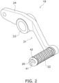
FIG. 2 is a perspective view of theshift pedal 18.FIG. 3 is a top view of theshift pedal 18.FIG. 4 is a side view of theshift pedal 18. As shown inFIGS. 2 to 4 , theshift pedal 18 includes apedal body 21 and acover 22. Thepedal body 21 is rotatably attached to the vehicle body 2. Thepedal body 21 is made of metal such as aluminum. -
FIG. 5 is a perspective view of thepedal body 21. As shown inFIG. 5 , thepedal body 21 includes ashaft portion 23, anarm portion 24, and apedal tread portion 25. Theshaft portion 23 is rotatably supported by the vehicle body 2. Theshaft portion 23 projects laterally from thearm portion 24. Thearm portion 24 has a plate shape. Thearm portion 24 extends from theshaft portion 23 in the front-rear direction. -
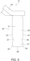
FIGS. 6 to 8 are enlarged views of thepedal body 21 showing the vicinity of thepedal tread portion 25. As shown inFIGS. 6 to 8 , thepedal tread portion 25 projects laterally from thearm portion 24. Thepedal tread portion 25 is made of sheet metal. Thepedal tread portion 25 is connected to thearm portion 24 by, for example, welding. Thepedal tread portion 25 has a plate shape that is bent convexly upward. - As shown in
FIG. 6 , thepedal tread portion 25 includes aninner lateral portion 26 and an outerlateral portion 27. Theinner lateral portion 26 is connected to thearm portion 24. The outerlateral portion 27 is arranged further laterally outward than theinner lateral portion 26. The outerlateral portion 27 of thepedal tread portion 25 includes apedal end 28. Thepedal end 28 is located at the outermost lateral side of thepedal tread portion 25. The outerlateral portion 27 has the same width as theinner lateral portion 26 in the front-rear direction of the vehicle. The outerlateral portion 27 and theinner lateral portion 26 have a maximum width in thepedal tread portion 25 in the front-rear direction of the vehicle. - The
pedal tread portion 25 includes anupper surface 31, abottom surface 32, afirst edge 33, and asecond edge 34. Theupper surface 31 has a curved shape convexly upward. Thebottom surface 32 has a curved shape concave upward. Thefirst edge 33 and thesecond edge 34 extend in the left-right direction of the vehicle. Thefirst edge 33 and thesecond edge 34 extend linearly. Thesecond edge 34 is located opposite thefirst edge 33. Thefirst edge 33 is located on the front side of thepedal tread portion 25, and thesecond edge 34 is located on the rear side of thepedal tread portion 25. As shown inFIG. 6 , thecorner 35 between thefirst edge 33 and thepedal end 28 is rounded. Thecorner 36 between thesecond edge 34 and thepedal end 28 is rounded. - The
pedal tread portion 25 includes afirst notch 37 and asecond notch 38. Thefirst notch 37 is provided in thefirst edge 33. Thefirst notch 37 has a shape recessed rearward from thefirst edge 33. Thefirst notch 37 is arranged facing forward. Thesecond notch 38 is provided in thesecond edge 34. Thesecond notch 38 has a shape recessed forward from thesecond edge 34. Thesecond notch 38 is arranged facing rearward. - The
first notch 37 and thesecond notch 38 are arranged between theinner lateral portion 26 and the outerlateral portion 27. Thefirst notch 37 and thesecond notch 38 are arranged side by side in the front-rear direction of the vehicle. Thefirst notch 37 and thesecond notch 38 are arranged on the outer lateral side of the center of thepedal tread portion 25 in the left-right direction of the vehicle. Thefirst notch 37 and thesecond notch 38 have a smoothly curved shape. - The
pedal body 21 includes a reinforcingmember 39. The reinforcingmember 39 projects laterally from thearm portion 24. The reinforcingmember 39 has a cylindrical shape. The reinforcingmember 39 is connected to thearm portion 24 by, for example, welding. The reinforcingmember 39 is arranged below thepedal tread portion 25. The reinforcingmember 39 is in contact with thebottom surface 32 of thepedal tread portion 25. The reinforcingmember 39 supports thepedal tread portion 25 from below. - The
cover 22 is separate from thepedal body 21. Thecover 22 is attached to thepedal body 21. Thecover 22 is made of an elastic material such as rubber. Thecover 22 covers thepedal tread portion 25.FIG. 9 is an enlarged view of theshift pedal 18 showing thecover 22 and the vicinity of thepedal tread portion 25.FIG. 10 is a perspective view of thecover 22. As shown inFIGS. 9 and10 , thecover 22 has a flattened shape that is longer in the front-rear direction than in the vertical direction. - The
cover 22 includes acover end 41 and ahole 42. Thecover end 41 is located at the outermost lateral side of thecover 22. Thehole 42 extends in the left-right direction. Thehole 42 penetrates thecover 22 in the left-right direction. Thehole 42 is open at thecover end 41. Similar to thepedal tread portion 25, thehole 42 has a bent shape convexly upward. - The
hole 42 includes an upperinner surface 43, a lowerinner surface 44, a frontinner surface 45, and a rearinner surface 46. The upperinner surface 43 is curved convexly upward. The lowerinner surface 44 is curved convexly upward. Thehole 42 extends in a curved line from the frontinner surface 45 toward the rearinner surface 46. Thepedal tread portion 25 is inserted into thehole 42. Thepedal tread portion 25 is press-fitted into thehole 42. Thereby, thecover 22 is attached to thepedal body 21. Theupper surface 31 of thepedal tread portion 25 contacts the upperinner surface 43. Thebottom surface 32 of thepedal tread portion 25 contacts the lowerinner surface 44. Thefirst edge 33 of thepedal tread portion 25 contacts the frontinner surface 45. Thesecond edge 34 contacts the rearinner surface 46. - The
cover 22 includes an uppercurved surface 47 and a lowercurved surface 48. The uppercurved surface 47 is provided on the upper surface of thecover 22. The uppercurved surface 47 is curved convexly upward. The lowercurved surface 48 is provided on the lower surface of thecover 22. The lowercurved surface 48 is curved convexly downward. The uppercurved surface 47 and the lowercurved surface 48 are provided with anti-slip grooves. The curvature of the lowercurved surface 48 is greater than the curvature of the uppercurved surface 47. - The
cover 22 includes alower cover portion 51 and anupper cover portion 52. Thelower cover portion 51 is located below thepedal tread portion 25. Thelower cover portion 51 is arranged facing thebottom surface 32 of thepedal tread portion 25. Theupper cover portion 52 is located above thepedal tread portion 25. Theupper cover portion 52 is arranged facing theupper surface 31 of thepedal tread portion 25. The thickness of thelower cover portion 51 in the vertical direction is greater than the thickness of theupper cover portion 52 in the vertical direction. - As shown in
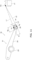
FIG. 11 , a contact point between a first tangent line L1 and thecover 22 is defined as an upper contact point P1 as seen in the vehicle side view. The first tangent line L1 passes through a predetermined position P3 on thefoot step 17 and contacts thecover 22 from above. The predetermined position P3 is, for example, the front end of the upper surface of thefoot step 17. Alternatively, the predetermined position P3 may be any other position on the upper surface of thefoot step 17. As seen in the vehicle side view, a contact point between a second tangent line L2 and thecover 22 is defined as a lower contact point P2. The second tangent line L2 passes through the predetermined position P3 on thefoot step 17 and contacts thecover 22 from below. As seen in the vehicle side view, a direction in which a straight line L3 connecting the upper contact point P1 and the lower contact point P2 extends is defined as an operating direction A1 of a rider's foot. As shown inFIG. 11 , as seen in the vehicle side view, a dimension S1 of thecover 22 in the operating directionAl is smaller than a dimension S2 of thecover 22 in a direction perpendicular to the operating directionAl. -
FIG. 12 is a sectional view taken along the line XII-XII of theshift pedal 18 inFIG. 9 . As shown inFIG. 12 , thepedal tread portion 25 is arranged within thehole 42. Thepedal end 28 is arranged further laterally inward than thecover end 41. Thecover 22 includes afirst protrusion 53 and asecond protrusion 54. Thefirst protrusion 53 and thesecond protrusion 54 protrude from the inner surface of thehole 42. Thefirst protrusion 53 protrudes from the frontinner surface 45. Thefirst protrusion 53 is engaged with thefirst notch 37 within thehole 42. Thesecond protrusion 54 protrudes from the rearinner surface 46. Thesecond protrusion 54 is engaged with thesecond notch 38 within thehole 42. Thereby, thecover 22 is prevented from coming off from thepedal tread portion 25. - According to the straddled
vehicle 1 according to the present embodiment, the first protrusion53 engages with thefirst notch 37 in thehole 42, so that thecover 22 is prevented from coming off with respect to thepedal tread portion 25. Therefore, thecover 22 made of an elastic material is firmly prevented from coming off from thepedal tread portion 25, and thecover 22 can be easily attached to thepedal tread portion 25. - Although one embodiment of the present invention has been described above, the present invention is not limited to the above embodiment, and various changes can be made without departing from the gist of the invention.
- The straddled
vehicle 1 is not limited to an off-road type, but may be another type of vehicle such as a street type or a moped. The shape of theshift pedal 18 is not limited to that of the embodiment described above, and may be changed.FIG. 13 is a sectional view of ashift pedal 18 according to a first modification. As shown inFIG. 13 , thepedal end 28 may be disposed flush with thecover end 41. - The shape of the
pedal tread portion 25 is not limited to that of the above embodiment, and may be changed. The shape of thecover 22 is not limited to that of the above embodiment, and may be changed. For example,FIG. 14 is an enlarged view of thepedal body 21 showing the vicinity of thepedal tread portion 25 according to the second modification.FIG. 15 is an enlarged view of theshift pedal 18 showing the vicinity of thepedal tread portion 25 according to the second modification. As shown inFIGS. 14 and15 , thepedal tread portion 25 may have a cylindrical shape. Thecover 22 may have a cylindrical shape. - 2: Vehicle body, 18: Shift pedal, 22: Cover, 23: Shaft portion, 24: Arm portion, 25: Pedal tread portion, 26: Inner lateral portion, 27: Outer lateral portion, 28: Pedal end, 33: First edge, 34: Second edge, 37: First notch, 38: Second notch, 41: Cover end, 42: Hole, 53: First protrusion, 54: Second protrusion
Claims (7)
- A straddled vehicle (1) comprising:a vehicle body (2); anda shift pedal (18) attached to the vehicle body (2), whereinthe shift pedal (18) includes:a shaft portion (23) rotatably supported by the vehicle body (2),an arm portion (24) extending in a front-rear direction of the vehicle from the shaft portion (23),a pedal tread portion (25) projecting laterally from the arm portion (24), anda cover (22) that is made of an elastic material and covers the pedal tread portion (25),the pedal tread portion (25) including:an inner lateral portion (26) connected to the arm portion (24),an outer lateral portion (27) disposed further laterally outward than the inner lateral portion (26), anda first notch (37) disposed between the inner lateral portion (26) and the outer lateral portion (27),the outer lateral portion (27) has a same width as the inner lateral portion (26) in the front-rear direction of the vehicle (1),the cover (22) including:a hole (42) into which the pedal tread portion (25) is inserted, anda first protrusion (53) protruding from an inner surface of the hole (42), andthe first protrusion (53) beings engaged with the first notch (37) in the hole (42) so that the cover (22) is prevented from coming off from the pedal tread portion (25).
- The straddled vehicle according to claim 1, whereinthe outer lateral portion (27) includes a pedal end (28) located at an outermost lateral side in the pedal tread portion (25),the cover (22) includes a cover end (41) located at an outermost lateral side in the cover (22), andthe pedal end (28) is flush with the cover end (41), or is arranged further laterally inward than the cover end (41).
- The straddled vehicle according to claim 1 or 2, wherein
the pedal tread portion (25) has a plate shape. - The straddled vehicle according to claim 3, whereinthe pedal tread portion (25) includesa first edge (33) extending in a left-right direction of the vehicle (1),a second edge (34) extending in the left-right direction of the vehicle (1) and arranged on an opposite side of the first edge (33), anda second notch (38) arranged between the inner lateral portion (26) and the outer lateral portion (27),the cover (22) includes a second protrusion (54) protruding from the inner surface of the hole (42),the second protrusion (54) is engaged with the second notch (38) in the hole (42) so that the cover (22) is prevented from coming off from the pedal tread portion (25),the first notch (37) is provided in the first edge (33), andthe second notch (38) is provided in the second edge (34).
- The straddled vehicle according to any one of claims 1 to 4, wherein
the outer lateral portion (27) and the inner lateral portion (26) have a maximum width at the pedal tread portion (25) in the front-rear direction of the vehicle (1). - The straddled vehicle according to any one of claims 1 to 5, wherein
the first notch (37) is arranged on an outer lateral side of a center of the pedal tread portion (25) in the left-right direction of the vehicle (1). - The straddled vehicle according to any one of claims 1 to 6, wherein
the first notch (37) has a curved shape.
Applications Claiming Priority (1)
| Application Number | Priority Date | Filing Date | Title |
|---|---|---|---|
| JP2023091565A JP2024173256A (en) | 2023-06-02 | 2023-06-02 | Saddle-type vehicle |
Publications (2)
| Publication Number | Publication Date |
|---|---|
| EP4470895A1 true EP4470895A1 (en) | 2024-12-04 |
| EP4470895B1 EP4470895B1 (en) | 2025-06-18 |
Family
ID=89427155
Family Applications (1)
| Application Number | Title | Priority Date | Filing Date |
|---|---|---|---|
| EP23220507.0A Active EP4470895B1 (en) | 2023-06-02 | 2023-12-28 | Straddled vehicle |
Country Status (3)
| Country | Link |
|---|---|
| EP (1) | EP4470895B1 (en) |
| JP (1) | JP2024173256A (en) |
| CN (1) | CN119058874A (en) |
Citations (3)
| Publication number | Priority date | Publication date | Assignee | Title |
|---|---|---|---|---|
| JPS50137750U (en) * | 1974-04-30 | 1975-11-13 | ||
| WO2006011441A1 (en) | 2004-07-26 | 2006-02-02 | Yamaha Hatsudoki Kabushiki Kaisha | Shift controller of saddle-riding type vehicle |
| US7568403B2 (en) * | 2005-07-27 | 2009-08-04 | Kawasaki Jukogyo Kabushiki Kaisha | Transmission and motorcycle comprising the same |
-
2023
- 2023-06-02 JP JP2023091565A patent/JP2024173256A/en active Pending
- 2023-12-28 EP EP23220507.0A patent/EP4470895B1/en active Active
-
2024
- 2024-04-26 CN CN202410510471.0A patent/CN119058874A/en active Pending
Patent Citations (3)
| Publication number | Priority date | Publication date | Assignee | Title |
|---|---|---|---|---|
| JPS50137750U (en) * | 1974-04-30 | 1975-11-13 | ||
| WO2006011441A1 (en) | 2004-07-26 | 2006-02-02 | Yamaha Hatsudoki Kabushiki Kaisha | Shift controller of saddle-riding type vehicle |
| US7568403B2 (en) * | 2005-07-27 | 2009-08-04 | Kawasaki Jukogyo Kabushiki Kaisha | Transmission and motorcycle comprising the same |
Also Published As
| Publication number | Publication date |
|---|---|
| EP4470895B1 (en) | 2025-06-18 |
| CN119058874A (en) | 2024-12-03 |
| JP2024173256A (en) | 2024-12-12 |
Similar Documents
| Publication | Publication Date | Title |
|---|---|---|
| US8905168B2 (en) | Utility vehicle | |
| EP3398844A1 (en) | Mudguard member for saddled vehicle | |
| US6835904B2 (en) | Brake assembly for an all terrain vehicle and method of making same | |
| JP5331542B2 (en) | Step floor structure | |
| JP4856405B2 (en) | Transmission, motorcycle, and vehicle | |
| EP4470895B1 (en) | Straddled vehicle | |
| US9944342B2 (en) | Straddle-type vehicle | |
| EP4470894A1 (en) | Straddled vehicle | |
| US20060260858A1 (en) | Number plate for a straddle type vehicle | |
| CN111936344A (en) | Working vehicle | |
| JP2001001975A (en) | Brake pedal device for saddle type vehicle | |
| US10730582B2 (en) | Brake pedal device and saddle-ride type vehicle | |
| JP4574381B2 (en) | Step structure for motorcycle driver | |
| JP2009154843A (en) | Front fender and motorcycle | |
| KR20090003149U (en) | Handlebars for Bicycles with Speedometer | |
| US12344343B2 (en) | Straddled vehicle | |
| EP4424578A1 (en) | Straddled vehicle | |
| JP7396081B2 (en) | Cover structure for saddle type vehicles | |
| JP2020057049A (en) | Lever support structure | |
| JP2001114177A (en) | Operating lever of hydraulic master cylinder for bar handle vehicle | |
| WO2018179746A1 (en) | Saddle-type vehicle | |
| JP2019018759A (en) | Seat structure | |
| CN111183092A (en) | Rubber pedal structure | |
| JP2001278175A (en) | Saddle-ride type vehicle with automatic transmission | |
| JP4236192B2 (en) | Braking device for saddle riding type vehicle |
Legal Events
| Date | Code | Title | Description |
|---|---|---|---|
| PUAI | Public reference made under article 153(3) epc to a published international application that has entered the european phase |
Free format text: ORIGINAL CODE: 0009012 |
|
| STAA | Information on the status of an ep patent application or granted ep patent |
Free format text: STATUS: REQUEST FOR EXAMINATION WAS MADE |
|
| 17P | Request for examination filed |
Effective date: 20231228 |
|
| AK | Designated contracting states |
Kind code of ref document: A1 Designated state(s): AL AT BE BG CH CY CZ DE DK EE ES FI FR GB GR HR HU IE IS IT LI LT LU LV MC ME MK MT NL NO PL PT RO RS SE SI SK SM TR |
|
| GRAP | Despatch of communication of intention to grant a patent |
Free format text: ORIGINAL CODE: EPIDOSNIGR1 |
|
| STAA | Information on the status of an ep patent application or granted ep patent |
Free format text: STATUS: GRANT OF PATENT IS INTENDED |
|
| P01 | Opt-out of the competence of the unified patent court (upc) registered |
Free format text: CASE NUMBER: APP_66692/2024 Effective date: 20241217 |
|
| INTG | Intention to grant announced |
Effective date: 20250109 |
|
| GRAS | Grant fee paid |
Free format text: ORIGINAL CODE: EPIDOSNIGR3 |
|
| GRAA | (expected) grant |
Free format text: ORIGINAL CODE: 0009210 |
|
| STAA | Information on the status of an ep patent application or granted ep patent |
Free format text: STATUS: THE PATENT HAS BEEN GRANTED |
|
| AK | Designated contracting states |
Kind code of ref document: B1 Designated state(s): AL AT BE BG CH CY CZ DE DK EE ES FI FR GB GR HR HU IE IS IT LI LT LU LV MC ME MK MT NL NO PL PT RO RS SE SI SK SM TR |
|
| REG | Reference to a national code |
Ref country code: GB Ref legal event code: FG4D |
|
| REG | Reference to a national code |
Ref country code: CH Ref legal event code: EP |
|
| REG | Reference to a national code |
Ref country code: DE Ref legal event code: R096 Ref document number: 602023004115 Country of ref document: DE |
|
| REG | Reference to a national code |
Ref country code: CH Ref legal event code: EP |
|
| REG | Reference to a national code |
Ref country code: IE Ref legal event code: FG4D |
|
| PG25 | Lapsed in a contracting state [announced via postgrant information from national office to epo] |
Ref country code: FI Free format text: LAPSE BECAUSE OF FAILURE TO SUBMIT A TRANSLATION OF THE DESCRIPTION OR TO PAY THE FEE WITHIN THE PRESCRIBED TIME-LIMIT Effective date: 20250618 |
|
| REG | Reference to a national code |
Ref country code: LT Ref legal event code: MG9D |
|
| PG25 | Lapsed in a contracting state [announced via postgrant information from national office to epo] |
Ref country code: GR Free format text: LAPSE BECAUSE OF FAILURE TO SUBMIT A TRANSLATION OF THE DESCRIPTION OR TO PAY THE FEE WITHIN THE PRESCRIBED TIME-LIMIT Effective date: 20250919 Ref country code: NO Free format text: LAPSE BECAUSE OF FAILURE TO SUBMIT A TRANSLATION OF THE DESCRIPTION OR TO PAY THE FEE WITHIN THE PRESCRIBED TIME-LIMIT Effective date: 20250918 |
|
| PG25 | Lapsed in a contracting state [announced via postgrant information from national office to epo] |
Ref country code: BG Free format text: LAPSE BECAUSE OF FAILURE TO SUBMIT A TRANSLATION OF THE DESCRIPTION OR TO PAY THE FEE WITHIN THE PRESCRIBED TIME-LIMIT Effective date: 20250618 |
|
| PG25 | Lapsed in a contracting state [announced via postgrant information from national office to epo] |
Ref country code: HR Free format text: LAPSE BECAUSE OF FAILURE TO SUBMIT A TRANSLATION OF THE DESCRIPTION OR TO PAY THE FEE WITHIN THE PRESCRIBED TIME-LIMIT Effective date: 20250618 |
|
| PG25 | Lapsed in a contracting state [announced via postgrant information from national office to epo] |
Ref country code: RS Free format text: LAPSE BECAUSE OF FAILURE TO SUBMIT A TRANSLATION OF THE DESCRIPTION OR TO PAY THE FEE WITHIN THE PRESCRIBED TIME-LIMIT Effective date: 20250918 |
|
| REG | Reference to a national code |
Ref country code: NL Ref legal event code: MP Effective date: 20250618 |
|
| PG25 | Lapsed in a contracting state [announced via postgrant information from national office to epo] |
Ref country code: LV Free format text: LAPSE BECAUSE OF FAILURE TO SUBMIT A TRANSLATION OF THE DESCRIPTION OR TO PAY THE FEE WITHIN THE PRESCRIBED TIME-LIMIT Effective date: 20250618 |
|
| PG25 | Lapsed in a contracting state [announced via postgrant information from national office to epo] |
Ref country code: NL Free format text: LAPSE BECAUSE OF FAILURE TO SUBMIT A TRANSLATION OF THE DESCRIPTION OR TO PAY THE FEE WITHIN THE PRESCRIBED TIME-LIMIT Effective date: 20250618 |
|
| PG25 | Lapsed in a contracting state [announced via postgrant information from national office to epo] |
Ref country code: PT Free format text: LAPSE BECAUSE OF FAILURE TO SUBMIT A TRANSLATION OF THE DESCRIPTION OR TO PAY THE FEE WITHIN THE PRESCRIBED TIME-LIMIT Effective date: 20251020 |
|
| REG | Reference to a national code |
Ref country code: AT Ref legal event code: MK05 Ref document number: 1803973 Country of ref document: AT Kind code of ref document: T Effective date: 20250618 |
|
| PG25 | Lapsed in a contracting state [announced via postgrant information from national office to epo] |
Ref country code: IS Free format text: LAPSE BECAUSE OF FAILURE TO SUBMIT A TRANSLATION OF THE DESCRIPTION OR TO PAY THE FEE WITHIN THE PRESCRIBED TIME-LIMIT Effective date: 20251018 |
|
| PGFP | Annual fee paid to national office [announced via postgrant information from national office to epo] |
Ref country code: DE Payment date: 20251211 Year of fee payment: 3 |
|
| PG25 | Lapsed in a contracting state [announced via postgrant information from national office to epo] |
Ref country code: AT Free format text: LAPSE BECAUSE OF FAILURE TO SUBMIT A TRANSLATION OF THE DESCRIPTION OR TO PAY THE FEE WITHIN THE PRESCRIBED TIME-LIMIT Effective date: 20250618 Ref country code: SM Free format text: LAPSE BECAUSE OF FAILURE TO SUBMIT A TRANSLATION OF THE DESCRIPTION OR TO PAY THE FEE WITHIN THE PRESCRIBED TIME-LIMIT Effective date: 20250618 |
|
| PGFP | Annual fee paid to national office [announced via postgrant information from national office to epo] |
Ref country code: FR Payment date: 20251229 Year of fee payment: 3 |
|
| PG25 | Lapsed in a contracting state [announced via postgrant information from national office to epo] |
Ref country code: CZ Free format text: LAPSE BECAUSE OF FAILURE TO SUBMIT A TRANSLATION OF THE DESCRIPTION OR TO PAY THE FEE WITHIN THE PRESCRIBED TIME-LIMIT Effective date: 20250618 |
|
| PG25 | Lapsed in a contracting state [announced via postgrant information from national office to epo] |
Ref country code: PL Free format text: LAPSE BECAUSE OF FAILURE TO SUBMIT A TRANSLATION OF THE DESCRIPTION OR TO PAY THE FEE WITHIN THE PRESCRIBED TIME-LIMIT Effective date: 20250618 |
|
| PG25 | Lapsed in a contracting state [announced via postgrant information from national office to epo] |
Ref country code: EE Free format text: LAPSE BECAUSE OF FAILURE TO SUBMIT A TRANSLATION OF THE DESCRIPTION OR TO PAY THE FEE WITHIN THE PRESCRIBED TIME-LIMIT Effective date: 20250618 |
|
| PG25 | Lapsed in a contracting state [announced via postgrant information from national office to epo] |
Ref country code: SK Free format text: LAPSE BECAUSE OF FAILURE TO SUBMIT A TRANSLATION OF THE DESCRIPTION OR TO PAY THE FEE WITHIN THE PRESCRIBED TIME-LIMIT Effective date: 20250618 |
|
| PG25 | Lapsed in a contracting state [announced via postgrant information from national office to epo] |
Ref country code: ES Free format text: LAPSE BECAUSE OF FAILURE TO SUBMIT A TRANSLATION OF THE DESCRIPTION OR TO PAY THE FEE WITHIN THE PRESCRIBED TIME-LIMIT Effective date: 20250618 |
|
| PG25 | Lapsed in a contracting state [announced via postgrant information from national office to epo] |
Ref country code: RO Free format text: LAPSE BECAUSE OF FAILURE TO SUBMIT A TRANSLATION OF THE DESCRIPTION OR TO PAY THE FEE WITHIN THE PRESCRIBED TIME-LIMIT Effective date: 20250618 |
|
| REG | Reference to a national code |
Ref country code: DE Ref legal event code: R097 Ref document number: 602023004115 Country of ref document: DE |
|
| PG25 | Lapsed in a contracting state [announced via postgrant information from national office to epo] |
Ref country code: DK Free format text: LAPSE BECAUSE OF FAILURE TO SUBMIT A TRANSLATION OF THE DESCRIPTION OR TO PAY THE FEE WITHIN THE PRESCRIBED TIME-LIMIT Effective date: 20250618 |
|
| PGFP | Annual fee paid to national office [announced via postgrant information from national office to epo] |
Ref country code: IT Payment date: 20251231 Year of fee payment: 3 |
|
| PLBE | No opposition filed within time limit |
Free format text: ORIGINAL CODE: 0009261 |
|
| STAA | Information on the status of an ep patent application or granted ep patent |
Free format text: STATUS: NO OPPOSITION FILED WITHIN TIME LIMIT |
|
| REG | Reference to a national code |
Ref country code: CH Ref legal event code: L10 Free format text: ST27 STATUS EVENT CODE: U-0-0-L10-L00 (AS PROVIDED BY THE NATIONAL OFFICE) Effective date: 20260430 |