EP4470855A1 - Twin chamber air dryer and electropneumatic system for a commercial vehicle - Google Patents
Twin chamber air dryer and electropneumatic system for a commercial vehicle Download PDFInfo
- Publication number
- EP4470855A1 EP4470855A1 EP23176049.7A EP23176049A EP4470855A1 EP 4470855 A1 EP4470855 A1 EP 4470855A1 EP 23176049 A EP23176049 A EP 23176049A EP 4470855 A1 EP4470855 A1 EP 4470855A1
- Authority
- EP
- European Patent Office
- Prior art keywords
- valve
- inlet
- dryer
- air
- twin chamber
- Prior art date
- Legal status (The legal status is an assumption and is not a legal conclusion. Google has not performed a legal analysis and makes no representation as to the accuracy of the status listed.)
- Pending
Links
Images

Classifications
-
- B—PERFORMING OPERATIONS; TRANSPORTING
- B60—VEHICLES IN GENERAL
- B60T—VEHICLE BRAKE CONTROL SYSTEMS OR PARTS THEREOF; BRAKE CONTROL SYSTEMS OR PARTS THEREOF, IN GENERAL; ARRANGEMENT OF BRAKING ELEMENTS ON VEHICLES IN GENERAL; PORTABLE DEVICES FOR PREVENTING UNWANTED MOVEMENT OF VEHICLES; VEHICLE MODIFICATIONS TO FACILITATE COOLING OF BRAKES
- B60T17/00—Component parts, details, or accessories of power brake systems not covered by groups B60T8/00, B60T13/00 or B60T15/00, or presenting other characteristic features
- B60T17/002—Air treatment devices
- B60T17/004—Draining and drying devices
-
- F—MECHANICAL ENGINEERING; LIGHTING; HEATING; WEAPONS; BLASTING
- F16—ENGINEERING ELEMENTS AND UNITS; GENERAL MEASURES FOR PRODUCING AND MAINTAINING EFFECTIVE FUNCTIONING OF MACHINES OR INSTALLATIONS; THERMAL INSULATION IN GENERAL
- F16K—VALVES; TAPS; COCKS; ACTUATING-FLOATS; DEVICES FOR VENTING OR AERATING
- F16K11/00—Multiple-way valves, e.g. mixing valves; Pipe fittings incorporating such valves
- F16K11/02—Multiple-way valves, e.g. mixing valves; Pipe fittings incorporating such valves with all movable sealing faces moving as one unit
- F16K11/04—Multiple-way valves, e.g. mixing valves; Pipe fittings incorporating such valves with all movable sealing faces moving as one unit comprising only lift valves
- F16K11/044—Multiple-way valves, e.g. mixing valves; Pipe fittings incorporating such valves with all movable sealing faces moving as one unit comprising only lift valves with movable valve members positioned between valve seats
-
- F—MECHANICAL ENGINEERING; LIGHTING; HEATING; WEAPONS; BLASTING
- F16—ENGINEERING ELEMENTS AND UNITS; GENERAL MEASURES FOR PRODUCING AND MAINTAINING EFFECTIVE FUNCTIONING OF MACHINES OR INSTALLATIONS; THERMAL INSULATION IN GENERAL
- F16K—VALVES; TAPS; COCKS; ACTUATING-FLOATS; DEVICES FOR VENTING OR AERATING
- F16K15/00—Check valves
- F16K15/02—Check valves with guided rigid valve members
- F16K15/06—Check valves with guided rigid valve members with guided stems
- F16K15/067—Check valves with guided rigid valve members with guided stems stem guided at two or more points
Definitions
- the invention generally relates to a twin chamber air dryer for an electropneumatic system of a commercial vehicle and an electropneumatic system comprising the twin chamber air dryer.
- Electropneumatic systems in commercial vehicles generally comprise a compressor, an air dryer unit for drying and filtering the compressed air delivered by the compressor, and consumer circuits supplied with the dried compressed air, wherein the consumer circuits in particular include pneumatic brake circuits and air suspension systems.
- the air dryer unit generally comprises one or more desiccant cartridges filled with moisture-absorbing materials like granulate.
- the compressed air is dried or de-moisturized in drying modes (supply modes), and the dried compressed air is then supplied to the subsequent consumer circuits.
- the desiccant cartridge is afterwards regenerated or purged in a regeneration mode, in which air flows in the reverse direction through the desiccant cartridge to a venting outlet.
- twin chamber air dryers which comprise two desiccant cartridges operated in alternating supplying modes.
- a first supply mode the compressed air flows through the first desiccant cartridge and a first inlet of the double check valve to an air outlet which is connected to the consumer circuits.
- the second desiccant cartridge is generally purged by a steady flow of compressed air flowing in the reverse direction.
- a control unit switches into the second supply mode, in which the air streams are reversed, thereby using the second desiccant cartridge for drying or de-moisturizing the compressed air and purging the first desiccant cartridge.
- An electropneumatic valve assembly is provided for switching between the two supply modes, the electropneumatic valve assembly can be controlled by an electronic control unit, which therefore switches between the supply modes.
- the double check valve usually consists of a valve casing with two valve seats each sealed by an own valve body, in particular valve balls.
- the valve bodes are therefore biased by a spring connecting the two valve bodies, each of the valve bodies serving as a check valve for closing its valve seat in the non-supply mode, and opening when charged with pressurized air from the inlet side of its valve seat.
- this conventional double check valve may cause oscillation or vibrations in the twin chamber air dryer, and therefore can lead to noise generation. Further, the check valve body oscillation can lead to wearing of the components, in particular a sealing o-ring, and therefore result in leakages.
- a twin chamber air dryer according to claim 1 is provides. Furthermore, an electropneumatic system comprising the twin chamber air dryer is provided.
- the subclaims describe preferred embodiments.
- the twin chamber air dryer comprises a double check valve with a valve body for closing both valve seats alternatingly, and without spring bias acting onto the valve body.
- only one single valve body is provided.
- valve body The pressure difference between the two valve inlets causes the valve body to seal the valve seat of the lower pressure channel.
- the valve body remains stationary until the next subsequent switching between the supply modes and cartridges, when the valve body changes its position and seals the other channel.
- the inventive features lead to a simplification of the hardware design, since the spring can be omitted and only one single valve body is inserted. Thus, the costs and bearing problems are reduced.
- the position of the valve body is only defined by the pressure difference; no additional spring forces act onto the valve body and therefore, oscillations due to counter-acting stream forces and spring forces cannot appear.
- a throttle function for bypassing the double check valve can be realized inside the double check valve, preferably in its valve body.
- the valve body can be provided with an orifice, which therefore provides a continuous air stream between the valve inlets.
- the air supply stream flows into the first valve inlet, through the valve interior and leaves the valve interior through the valve outlet; the purging air stream for regenerating the second desiccant cartridge flows through the orifice of the valve body, then into the outlet of the passive second desiccant cartridge and leaves the second desiccant cartridge at its inlet.
- the supply air stream flows correspondingly through the second desiccant cartridge, thereby regenerating the first desiccant cartridge.
- the valve body comprises a sealing ring receiving area, in particular a ring-shaped shoulder, for the two opposite sealing o-rings, and protrusions extending outwards from the sealing ring receiving area.
- the protrusions preferably extend into the respective valve inlets and/or supply conduits connecting the valve inlets; thus, the protrusions and the supply conduits together form a guiding or guidance for the valve body, which therefore is prevented from inclining or tilting in the valve interior. Thus, a safe guiding even without a spring bias is secured, without additional efforts or hardware equipment.
- the protrusions can be formed as rods, plates or blades extending in a lateral axial direction, for contacting the interior faces of the valve inlets and/or supply conduits.
- the twin chamber air dryer comprises a die-cast casing, in particular made of metal, in particular a die-cast casing containing the double check valve and at least a part of the additional valve subassembly.
- a check valve provided downstream of the valve outlet can be realized by a bore in the die-cast, said bore extending to the valve interior area of the double check valve.
- the double check valve can be realized by cavities or bores extending in the lateral direction, wherein the valve interior can be formed in a larger part of the cavity, one valve seat being realized by the die-cast casing, and the opposite valve seat being realized by a valve seat insert inserted into the die-cast casing.
- the valve assembly preferably comprises switching valves, in particular pneumatically controlled 3/2 switching valves connected to the respective cartridge inlets of the two dryer cartridges, wherein each switching valve connects the dryer inlet with either an air inlet of the twin chamber air dryer, to be connected to the compressor, or to a venting outlet for venting exhaust air from purging the desiccant cartridge.
- the control of the switching valves is preferably realized by an electropneumatic control valve, to be electrically controlled by an ECU.
- Fig. 1 depicts a pneumatic scheme of a twin chamber air dryer 1 according to an embodiment of the invention.
- the twin chamber air dryer 1 is provided in a commercial vehicle 2 as part of an electropneumatic system 3.
- the twin chamber air dryer 1 comprises several pneumatic ports: an air inlet 4 to be connected to a compressor 6, an air outlet 8, a second air outlet 9 connected to the first air outlet 8 via a blocking valve 12, a first venting outlet 14 and a second venting outlet 15, and a pneumatic control inlet 16.
- the air outlet 8 is connected to a gallery 10, which constitutes a pneumatic pipe system for supplying several pneumatic consumer circuits 11 of the commercial vehicle, in particular a brake system and a suspension system; the venting outlets 14 and 15 can be realized as a common single venting outlet to be connected to an exhaust.
- the twin chamber air dryer 1 comprises the following electric connections: a first electric control input 20 and a second electric control input 21, to be supplied with a control voltage U, as well as a first heating contact 23 and a second heating contact 24, for supplying a heating voltage to a heater element 25, in particular for heating the twin chamber air dryer 1 or a die-cast casing 51 of the twin chamber air dryer 1 and avoiding moisture condensation.
- the electric control inputs 20, 21 receive a control voltage U from an electronic control unit ECU 26, for switching between the drying modes or drying phases, as is described hereinafter.
- the twin chamber air dryer 1 is operated in first drying mode and a second drying mode (first and second drying phase or supply phase), wherein the ECU 26 switches the twin chamber air dryer 1 between the two drying modes.
- the twin chamber air dryer 1 comprises a first desiccant cartridge 30 and a second desiccant cartridge 31, both comprising moisture absorbing materials, e. g. granulates, a double check valve 32, and a pneumatic valve arrangement of pneumatic valves 12, 34, 36, 38, 40, 45 for switching between the first and second drying mode.
- the twin chamber air dryer 1 is supplied with compressed air from the compressor 6 to its inlet port 4, delivers dried compressed air via its air outlet 8, and exhausts or vents humid air via its venting outlet 14.
- the twin chamber air dryer 1 is switched in the first drying mode, in which the first desiccant cartridge 30 is active and dries compressed air received at the air inlet 4; the second desiccant cartridge 31 is passive and therefore switched into its regeneration phase for purging and de-moisturizing.
- compressed air is delivered from the compressor 6 into the air inlet 4 and an air supply line 43.
- a spring loaded pneumatically controlled 3/2-operating valve 40 remains in its open basic position and therefore, a branching point 41 of the air supply line 43 is provided with compressed air.
- a first switching valve 36 and a second switching valve 38 are each provided as pneumatically controlled 3/2 valves, which connect a cartridge input of the first desiccant cartridge 30 and the second desiccant cartridge 31 to either the air inlet 4 or the venting outlet 14, respectively, in an alternating manner.
- the first switching valve 36 connects the air inlet 4 to the first cartridge inlet 30a of the first desiccant cartridge 30, which dries the compressed air and delivers dried compressed air at its first cartridge outlet 30b, which, in turn, is connected to a pneumatic control port of the second switching valve 38.
- the second switching valve 38 is thereby activated and connects the second cartridge inlet 31a of the second cartridge 31 with the venting outlet 14.
- compressed air delivered into the air inlet 4 flows through the first desiccant cartridge 30, which absorbs the humidity in the compressed air, and dried compressed air is delivered from the first cartridge outlet 30b to the double check 32, which switches into its first open position and forwards the dried compressed air via a check valve 45 and an air outlet line 46 to the air outlet 8.
- Switching between the drying phases is accomplished by the ECU 26, which outputs a switching voltage U to the electric control inputs 20, 21, thereby electrifying a 3/2 solenoid (electropneumatic) control valve 34 and switching it from its depicted basic position into its actuated position, in which the pressurized air outlet line 46 is connected to the pneumatic control port of the first switching valve 36, thereby switching the first switching valve 36 into its actuated position, in which the connection between the air supply line 43 and the first cartridge inlet 30a is blocked, and the first cartridge inlet 30a is connected to the venting outlet 14.
- the ECU 26 which outputs a switching voltage U to the electric control inputs 20, 21, thereby electrifying a 3/2 solenoid (electropneumatic) control valve 34 and switching it from its depicted basic position into its actuated position, in which the pressurized air outlet line 46 is connected to the pneumatic control port of the first switching valve 36, thereby switching the first switching valve 36 into its actuated position, in which the connection between the air supply
- the compressed air in the first desiccant cartridge 30 and the pneumatic line between the first cartridge outlet 30b and the double check valve 32 is depressurized, and therefore, the connected pneumatic control port of the second switching valve 38 is depressurized and switches due to its spring load into its basic position, in which it connects the air supply line 43 with the second cartridge inlet 31a. Therefore, pressurized air supplied via the air supply line 43 is now delivered to the second cartridge inlet 31a, flows through the first desiccant cartridge 31 to the double check valve 32, and is afterwards delivered via the air outlet line 46 to the air outlet 8.
- the double check valve 32 comprises a throttle bypass 50 connecting the two cartridge outlets 30b and 31b and thereby enabling a small purging air stream from the respective pressurized cartridge outlet 30b or 31b to the passive cartridge outlet 31b or 30b, respectively, wherein the purging air stream flows through the passive desiccant cartridge 31 or 30 to the venting outlet 14.
- the throttle bypass 50 is realized internally in the double check valve 32.
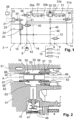
- Fig. 2 shows a cross-sectional view of relevant parts and elements of the twin chamber air dryer 1, including the double check valve 32 and the check valve 45.
- the double check valve 32 comprises a valve casing 52, which can be part of the die-cast casing 51 of the twin chamber air dryer 1, a valve interior 53, which in Fig. 2 is realized as a bore in the valve casing 52, a first valve seat 54 and a second valve seat 56, which are both formed in the valve casing 52, and a valve body 60 inserted into the valve interior 53.
- the valve body 60 is provided with a first sealing ring 55 for abutting on the first valve seat 54 and a second sealing ring 57 for abutting on the second valve seat 56.
- the double check valve 32 comprises a first valve inlet 61 connected to the first cartridge outlet 30b, a second valve inlet 62 connected to the second cartridge outlet 31b, and a valve outlet 63 connected to the check valve 45 and the air outlet line 46.
- the double check valve 32 therefore switches between its first valve position, corresponding to the first drying mode, in which the first valve inlet 61 is connected to the valve outlet 63, and the second valve position, in which the first valve inlet 61 is closed, and the open second valve inlet 62 is connected to the valve outlet 63.
- the valve body 60 is received in the valve casing 52 without spring load.
- the valve body 60 is realized by a single one-part body valve 60, which is shifted in an axial lateral direction A between the first valve seat 54 and the second valve seat 56.
- the pressure difference between the two valve inlets 61 and 62 shifts the valve body 60 to the lower pressure channel and therefore, the valve body 60 abuts on the lower pressure valve seat and seals it, thereby opening the air passage between the higher pressure channel and the valve outlet 63.
- the force generated by the pressure difference causes the double check valve 32 to remain stationary until the next subsequent switching between the drying modes occurs when the pressure difference changes and therefore, the force direction is switched or flipped, thereby forcing the valve body 60 to change its position and to seal the other channel.
- the valve body 60 comprises protrusions 66 extending in lateral direction into air conduits 58 provided as bores in the die-casted valve casing 52.
- the protrusions 66 and the air conduits 58 therefore serve as guidings for the valve body 60 in its lateral movement.
- one of the valve seats in this embodiment the second valve seat 56, is formed at a valve seat insert 72 inserted into the casing 52.
- a reverse configuration of the valve seats 54 and 56 is possible.
- the valve body 60 comprises two shoulders 74 for fixing the sealing rings (O-rings) 55 and 57.
- the throttle bypass 50 is realized as an orifice 80 in the internal walls, allowing a small air passage for venting the passive desiccant cartridge 31 or 30 from its cartridge inlet 31a or 30a, respectively, to its cartridge outlet 31b or 30b.
- the functional means of a throttle bypass 50 can be realized without additional hardware.
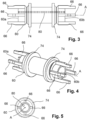
- the protrusions 66 of the first side 60a and the second side 60b of the valve body 60 comprise an equal or similar form, in particular with three rods extending in axial lateral direction A.
- the protrusions 66, 67 at the first side 60a and the second side 60b may differ.
- protrusions 66, 67 may be formed by rods or plates and/ or triangles or; the form of the protrusions 66 can be adapted to the form of the corresponding valve seats 54, 56 and air conduits connected to the valve seats 54, 56.
- the valve body 60 can be made of plastic material or metal, in particular as a single part. However, a construction of two parts permanently connected to each other, for example by welding, is also possible.
- the double check valve 52 and the check valve 45 are both realized by cavities or bores in the die-cast casing 51.
- the check valve 45 comprises a spring-loaded check valve body 47 received in a bore or cavity of the cast casing 51.
- Further valves of the valve assembly can also be formed in the die-cast casing 51.
Landscapes
- Engineering & Computer Science (AREA)
- General Engineering & Computer Science (AREA)
- Mechanical Engineering (AREA)
- Transportation (AREA)
- Valves And Accessory Devices For Braking Systems (AREA)
- Drying Of Gases (AREA)
Abstract
- an air inlet (4), an air outlet (8), a venting outlet (14),
- a valve arrangement for switching between a first and second drying mode,
- a double check valve (32) comprising a first and second valve inlet, a valve outlet, a valve interior, a first and second valve seat, and a valve body being provided in said valve interior,
- a first and second dryer cartridge (30, 31) connected to said first and second valve inlet, respectively,
said valve body being switchable between a first and second valve position corresponding to the first and second drying mode, in which an air passage between said first or second valve inlet and said valve outlet is open and the other valve inlet is closed.
Description
- The invention generally relates to a twin chamber air dryer for an electropneumatic system of a commercial vehicle and an electropneumatic system comprising the twin chamber air dryer.
- Electropneumatic systems in commercial vehicles generally comprise a compressor, an air dryer unit for drying and filtering the compressed air delivered by the compressor, and consumer circuits supplied with the dried compressed air, wherein the consumer circuits in particular include pneumatic brake circuits and air suspension systems. The air dryer unit generally comprises one or more desiccant cartridges filled with moisture-absorbing materials like granulate. The compressed air is dried or de-moisturized in drying modes (supply modes), and the dried compressed air is then supplied to the subsequent consumer circuits. The desiccant cartridge is afterwards regenerated or purged in a regeneration mode, in which air flows in the reverse direction through the desiccant cartridge to a venting outlet.
- To provide a continuous flow of compressed air, twin chamber air dryers are known, which comprise two desiccant cartridges operated in alternating supplying modes. In a first supply mode, the compressed air flows through the first desiccant cartridge and a first inlet of the double check valve to an air outlet which is connected to the consumer circuits. In this first supply mode, the second desiccant cartridge is generally purged by a steady flow of compressed air flowing in the reverse direction. Subsequently, a control unit switches into the second supply mode, in which the air streams are reversed, thereby using the second desiccant cartridge for drying or de-moisturizing the compressed air and purging the first desiccant cartridge. An electropneumatic valve assembly is provided for switching between the two supply modes, the electropneumatic valve assembly can be controlled by an electronic control unit, which therefore switches between the supply modes. The double check valve usually consists of a valve casing with two valve seats each sealed by an own valve body, in particular valve balls. The valve bodes are therefore biased by a spring connecting the two valve bodies, each of the valve bodies serving as a check valve for closing its valve seat in the non-supply mode, and opening when charged with pressurized air from the inlet side of its valve seat.
- However, the spring-mass configuration of this conventional double check valve may cause oscillation or vibrations in the twin chamber air dryer, and therefore can lead to noise generation. Further, the check valve body oscillation can lead to wearing of the components, in particular a sealing o-ring, and therefore result in leakages.
- It is therefore an object of the invention to provide a twin chamber air dryer and an electropneumatic system comprising such a twin chamber air dryer, which offer a steady supply of compressed air with reduced drawbacks.
- According to one aspect of the invention, a twin chamber air dryer according to claim 1 is provides. Furthermore, an electropneumatic system comprising the twin chamber air dryer is provided. The subclaims describe preferred embodiments.
- Thus, the twin chamber air dryer comprises a double check valve with a valve body for closing both valve seats alternatingly, and without spring bias acting onto the valve body. In particular, only one single valve body is provided.
- These amendments lead to a simplification of the double check valve and therefore to a reduction of costs. Furthermore, the above-mentioned problems of spring-mass systems and oscillations resulting from the air stream charging the valve body can be reduced or eliminated.
- The pressure difference between the two valve inlets causes the valve body to seal the valve seat of the lower pressure channel. Thus, the valve body remains stationary until the next subsequent switching between the supply modes and cartridges, when the valve body changes its position and seals the other channel.
- The inventive features lead to a simplification of the hardware design, since the spring can be omitted and only one single valve body is inserted. Thus, the costs and bearing problems are reduced. The position of the valve body is only defined by the pressure difference; no additional spring forces act onto the valve body and therefore, oscillations due to counter-acting stream forces and spring forces cannot appear.
- According to a preferred embodiment, a throttle function for bypassing the double check valve can be realized inside the double check valve, preferably in its valve body. In particular, the valve body can be provided with an orifice, which therefore provides a continuous air stream between the valve inlets.
- In the first supply mode, the air supply stream flows into the first valve inlet, through the valve interior and leaves the valve interior through the valve outlet; the purging air stream for regenerating the second desiccant cartridge flows through the orifice of the valve body, then into the outlet of the passive second desiccant cartridge and leaves the second desiccant cartridge at its inlet. In the second supply mode, the supply air stream flows correspondingly through the second desiccant cartridge, thereby regenerating the first desiccant cartridge. Thus, the additional function of the bypass throttle can be realized without further equipment, in particular only by forming an orifice in the valve body.
- According to a preferred embodiment, the valve body comprises a sealing ring receiving area, in particular a ring-shaped shoulder, for the two opposite sealing o-rings, and protrusions extending outwards from the sealing ring receiving area.
- The protrusions preferably extend into the respective valve inlets and/or supply conduits connecting the valve inlets; thus, the protrusions and the supply conduits together form a guiding or guidance for the valve body, which therefore is prevented from inclining or tilting in the valve interior. Thus, a safe guiding even without a spring bias is secured, without additional efforts or hardware equipment. The protrusions can be formed as rods, plates or blades extending in a lateral axial direction, for contacting the interior faces of the valve inlets and/or supply conduits.
- According to a preferred embodiment, the twin chamber air dryer comprises a die-cast casing, in particular made of metal, in particular a die-cast casing containing the double check valve and at least a part of the additional valve subassembly. For example, a check valve provided downstream of the valve outlet can be realized by a bore in the die-cast, said bore extending to the valve interior area of the double check valve. The double check valve can be realized by cavities or bores extending in the lateral direction, wherein the valve interior can be formed in a larger part of the cavity, one valve seat being realized by the die-cast casing, and the opposite valve seat being realized by a valve seat insert inserted into the die-cast casing. Thus, low-effort production and assembly can be realized.
- The valve assembly preferably comprises switching valves, in particular pneumatically controlled 3/2 switching valves connected to the respective cartridge inlets of the two dryer cartridges, wherein each switching valve connects the dryer inlet with either an air inlet of the twin chamber air dryer, to be connected to the compressor, or to a venting outlet for venting exhaust air from purging the desiccant cartridge. The control of the switching valves is preferably realized by an electropneumatic control valve, to be electrically controlled by an ECU.
- The invention is hereinafter described in detail with reference to the accompanying drawings, wherein
- Fig. 1
- is a pneumatic scheme of a twin chamber air dryer according to an embodiment of the invention;
- Fig. 2
- is a cross-sectional view of the casing with interior valves:
- Fig. 3
- is a side view of a valve body according to an embodiment of the invention;
- Fig. 4
- is a perspective view of the valve body of
fig. 3 ; - Fig. 5
- is a front view of the valve body of
fig. 3 ; - Fig. 6
- is a side view of a valve body according to a further embodiment of the invention; and
- Fig. 7
- is a perspective view of the valve body of
fig. 6 ; -
Fig. 1 depicts a pneumatic scheme of a twin chamber air dryer 1 according to an embodiment of the invention. The twin chamber air dryer 1 is provided in a commercial vehicle 2 as part of an electropneumatic system 3. The twin chamber air dryer 1 comprises several pneumatic ports:
an air inlet 4 to be connected to a compressor 6, anair outlet 8, asecond air outlet 9 connected to thefirst air outlet 8 via ablocking valve 12, afirst venting outlet 14 and asecond venting outlet 15, and apneumatic control inlet 16. - These
pneumatic ports
Theair outlet 8 is connected to agallery 10, which constitutes a pneumatic pipe system for supplying severalpneumatic consumer circuits 11 of the commercial vehicle, in particular a brake system and a suspension system; the ventingoutlets - Furthermore, the twin chamber air dryer 1 comprises the following electric connections: a first electric control input 20 and a second
electric control input 21, to be supplied with a control voltage U, as well as afirst heating contact 23 and asecond heating contact 24, for supplying a heating voltage to aheater element 25, in particular for heating the twin chamber air dryer 1 or a die-cast casing 51 of the twin chamber air dryer 1 and avoiding moisture condensation. Theelectric control inputs 20, 21 receive a control voltage U from an electroniccontrol unit ECU 26, for switching between the drying modes or drying phases, as is described hereinafter. - The twin chamber air dryer 1 is operated in first drying mode and a second drying mode (first and second drying phase or supply phase), wherein the
ECU 26 switches the twin chamber air dryer 1 between the two drying modes. For this purpose, the twin chamber air dryer 1 comprises afirst desiccant cartridge 30 and asecond desiccant cartridge 31, both comprising moisture absorbing materials, e. g. granulates, adouble check valve 32, and a pneumatic valve arrangement ofpneumatic valves air outlet 8, and exhausts or vents humid air via itsventing outlet 14. - In the basic state shown in
Fig. 1 , the twin chamber air dryer 1 is switched in the first drying mode, in which thefirst desiccant cartridge 30 is active and dries compressed air received at the air inlet 4; thesecond desiccant cartridge 31 is passive and therefore switched into its regeneration phase for purging and de-moisturizing. In this first drying mode, compressed air is delivered from the compressor 6 into the air inlet 4 and anair supply line 43. A spring loaded pneumatically controlled 3/2-operatingvalve 40 remains in its open basic position and therefore, a branchingpoint 41 of theair supply line 43 is provided with compressed air. - A
first switching valve 36 and asecond switching valve 38 are each provided as pneumatically controlled 3/2 valves, which connect a cartridge input of thefirst desiccant cartridge 30 and thesecond desiccant cartridge 31 to either the air inlet 4 or the ventingoutlet 14, respectively, in an alternating manner. In the depicted first drying mode, thefirst switching valve 36 connects the air inlet 4 to thefirst cartridge inlet 30a of thefirst desiccant cartridge 30, which dries the compressed air and delivers dried compressed air at itsfirst cartridge outlet 30b, which, in turn, is connected to a pneumatic control port of thesecond switching valve 38. Thesecond switching valve 38 is thereby activated and connects thesecond cartridge inlet 31a of thesecond cartridge 31 with the ventingoutlet 14. Thus, in the first drying mode, compressed air delivered into the air inlet 4 flows through thefirst desiccant cartridge 30, which absorbs the humidity in the compressed air, and dried compressed air is delivered from thefirst cartridge outlet 30b to thedouble check 32, which switches into its first open position and forwards the dried compressed air via acheck valve 45 and anair outlet line 46 to theair outlet 8. - Switching between the drying phases is accomplished by the
ECU 26, which outputs a switching voltage U to theelectric control inputs 20, 21, thereby electrifying a 3/2 solenoid (electropneumatic)control valve 34 and switching it from its depicted basic position into its actuated position, in which the pressurizedair outlet line 46 is connected to the pneumatic control port of thefirst switching valve 36, thereby switching thefirst switching valve 36 into its actuated position, in which the connection between theair supply line 43 and thefirst cartridge inlet 30a is blocked, and thefirst cartridge inlet 30a is connected to the ventingoutlet 14. Thus, the compressed air in thefirst desiccant cartridge 30 and the pneumatic line between thefirst cartridge outlet 30b and thedouble check valve 32 is depressurized, and therefore, the connected pneumatic control port of thesecond switching valve 38 is depressurized and switches due to its spring load into its basic position, in which it connects theair supply line 43 with thesecond cartridge inlet 31a. Therefore, pressurized air supplied via theair supply line 43 is now delivered to thesecond cartridge inlet 31a, flows through thefirst desiccant cartridge 31 to thedouble check valve 32, and is afterwards delivered via theair outlet line 46 to theair outlet 8. - The
double check valve 32 comprises athrottle bypass 50 connecting the twocartridge outlets pressurized cartridge outlet passive cartridge outlet passive desiccant cartridge outlet 14. In the embodiment describes hereinafter, thethrottle bypass 50 is realized internally in thedouble check valve 32. -
Fig. 2 shows a cross-sectional view of relevant parts and elements of the twin chamber air dryer 1, including thedouble check valve 32 and thecheck valve 45. Thedouble check valve 32 comprises avalve casing 52, which can be part of the die-cast casing 51 of the twin chamber air dryer 1, avalve interior 53, which inFig. 2 is realized as a bore in thevalve casing 52, afirst valve seat 54 and asecond valve seat 56, which are both formed in thevalve casing 52, and avalve body 60 inserted into thevalve interior 53. Thevalve body 60 is provided with afirst sealing ring 55 for abutting on thefirst valve seat 54 and asecond sealing ring 57 for abutting on thesecond valve seat 56. - The
double check valve 32 comprises afirst valve inlet 61 connected to thefirst cartridge outlet 30b, asecond valve inlet 62 connected to thesecond cartridge outlet 31b, and avalve outlet 63 connected to thecheck valve 45 and theair outlet line 46. Thedouble check valve 32 therefore switches between its first valve position, corresponding to the first drying mode, in which thefirst valve inlet 61 is connected to thevalve outlet 63, and the second valve position, in which thefirst valve inlet 61 is closed, and the opensecond valve inlet 62 is connected to thevalve outlet 63. Thevalve body 60 is received in thevalve casing 52 without spring load. Thevalve body 60 is realized by a single one-part body valve 60, which is shifted in an axial lateral direction A between thefirst valve seat 54 and thesecond valve seat 56. The pressure difference between the twovalve inlets valve body 60 to the lower pressure channel and therefore, thevalve body 60 abuts on the lower pressure valve seat and seals it, thereby opening the air passage between the higher pressure channel and thevalve outlet 63. The force generated by the pressure difference causes thedouble check valve 32 to remain stationary until the next subsequent switching between the drying modes occurs when the pressure difference changes and therefore, the force direction is switched or flipped, thereby forcing thevalve body 60 to change its position and to seal the other channel. - According to the embodiment of
fig. 2 to 5 , thevalve body 60 comprisesprotrusions 66 extending in lateral direction intoair conduits 58 provided as bores in the die-casted valve casing 52. Theprotrusions 66 and theair conduits 58 therefore serve as guidings for thevalve body 60 in its lateral movement. According to the embodiment offig. 2 , one of the valve seats, in this embodiment thesecond valve seat 56, is formed at avalve seat insert 72 inserted into thecasing 52. However, a reverse configuration of the valve seats 54 and 56 is possible. Thevalve body 60 comprises twoshoulders 74 for fixing the sealing rings (O-rings) 55 and 57. Thethrottle bypass 50 is realized as anorifice 80 in the internal walls, allowing a small air passage for venting thepassive desiccant cartridge cartridge inlet cartridge outlet throttle bypass 50 can be realized without additional hardware. - In the embodiments of
Fig. 2 to 5 , theprotrusions 66 of thefirst side 60a and thesecond side 60b of thevalve body 60 comprise an equal or similar form, in particular with three rods extending in axial lateral direction A. According to the embodiment ofFig. 6 and 7 , theprotrusions first side 60a and thesecond side 60b may differ. According toFig. 6, 7 ,protrusions protrusions 66 can be adapted to the form of the corresponding valve seats 54, 56 and air conduits connected to the valve seats 54, 56. - The
valve body 60 can be made of plastic material or metal, in particular as a single part. However, a construction of two parts permanently connected to each other, for example by welding, is also possible. - According to
Fig. 2 , thedouble check valve 52 and thecheck valve 45 are both realized by cavities or bores in the die-cast casing 51. Thecheck valve 45 comprises a spring-loadedcheck valve body 47 received in a bore or cavity of thecast casing 51. Thus, a simple, space-saving design with low costs can be realized. Further valves of the valve assembly can also be formed in the die-cast casing 51. -
- 1
- twin chamber air dryer
- 2
- commercial vehicle
- 3
- electropneumatic system
- 4
- air inlet
- 6
- compressor
- 8
- air outlet
- 9
- second air outlet
- 10
- gallery
- 11
- consumer circuits
- 12
- blocking valve, e. g. manually operated
- 14
- venting outlet
- 15
- second venting outlet
- 16
- pneumatic control inlet
- 20
- first electric control input
- 21
- second electric control input
- 23, 24
- heating contacts
- 26
- ECU
- 30
- first desiccant cartridge
- 30a
- first cartridge inlet
- 30b
- first cartridge outlet
- 31
- second desiccant cartridge
- 31a
- second cartridge inlet
- 31b
- second cartridge outlet
- 32
- double check valve
- 34
- electropneumatic 3/2 control valve
- 36
- first switching valve
- 38
- second switching valve
- 40
- spring loaded pneumatically controlled 3/2-operating valve
- 41
- branching point
- 43
- air supply line
- 45
- check valve
- 46
- air outlet line
- 47
- check valve body of the
check valve 45 - 50
- throttle bypass
- 51
- die-cast casing of the twin chamber air dryer 1
- 52
- valve casing of the
double check valve 32, realized as part of the die-cast casing 51 - 53
- valve interior
- 54
- first valve seat
- 55
- first sealing ring
- 56
- second valve seat
- 57
- second sealing ring
- 58
- air conduits
- 60
- valve body
- 61
- first valve inlet
- 62
- second valve inlet
- 63
- valve outlet
- 66
- protrusions with rods
- 67
- protrusions with plates
- 72
- valve seat insert
- 74
- shoulders
- 75
- internal wall
- 80
- orifice
- A
- lateral direction
Claims (11)
- A twin chamber air dryer (1), for use in an electropneumatic system (3) of a commercial vehicle (2), said twin chamber air dryer (1) comprising:- an air inlet (4) to be supplied with compressed air from a compressor (6),- an air outlet (8) for delivering dried compressed air,- a venting outlet (14) for exhausting air,- a valve arrangement (12, 34, 36, 38, 40, 45),- a double check valve (32), said double check valve (32) comprising a first valve inlet (61), a second valve inlet (62), a valve outlet (63), a valve casing (52) containing a valve interior (53), a first valve seat (54), a second valve seat (56), and a valve body (60) being provided in said valve interior (53),- a throttle bypass (50) connecting said first valve inlet (61) and said second valve inlet (62),- a first dryer cartridge (30) connected to said first valve inlet (61), and a second dryer cartridge (31) connected to said second valve inlet (62),said valve body (60) being switchable between- a first valve position corresponding to a first drying mode, in which an air passage between said first valve inlet (61) and said valve outlet (63) is open and said second valve inlet (62) is closed, and- a second valve position corresponding to a second drying mode, in which an air passage between said second valve inlet (62) and said valve outlet (63) is open and said first valve inlet (61) is closed,said valve arrangement (12, 34, 36, 38, 40, 45) being provided to switch said twin chamber air dryer (1) between said first drying mode and said second drying mode, characterized in thatsaid valve body (60) is provided in said valve interior (53) without spring bias, and said valve body (60) is displaceable between said first valve seat (54) and said second valve seat (56).
- A twin chamber air dryer (1) according to claim 1, wherein said valve arrangement (12, 34, 36, 38, 40, 45) is provided for switching between said first drying mode and said second drying mode by connecting said dryer cartridges (30, 31) and said double check valve (32) selectively with said air inlet (4), said air outlet (8), and said venting outlet (14).
- A twin chamber air dryer (1) according to claim 1 or 2, wherein said throttle bypass (50) is realized as an orifice (80) provided in said valve body (60), said orifice (80) comprising a smaller cross-sectional area than said valve inlets (61, 62) and/ or said valve seats (54, 56).
- A twin chamber air dryer (1) according to one of the preceding claims, whereinsaid valve body (60) is made as a single one-piece body, orsaid valve body (60) is made of two or more parts being permanently connected.
- A twin chamber air dryer (1) according to one of the preceding claims, whereinsaid valve body (60) is displaceable in a lateral direction (A) and comprises protrusions (66, 67) at its lateral ends,said protrusions (66, 67) extending into said first valve inlet (61) and said second valve inlet (62), respectively,said protrusions (66, 67) being guided in said valve inlets (61, 62) and/orsaid valve body (60) being guided by said protrusions (66, 67) in its displacement motion between said first and second valve position.
- A twin chamber air dryer (1) according to claim 5, whereinsaid valve body (60) comprises sealing ring receiving areas (74) at its lateral ends (60a, 60b),a sealing ring (55) being disposed on each of said sealing ring receiving areas (74), respectively,said protrusions (66, 67) extending from said ring sealing receiving areas (74) outwards into said valve inlets (61, 62), respectively.
- A twin chamber air dryer (1) according to claim 6, wherein each of said sealing ring receiving areas (74) comprises a shoulder formed as an annular wall or ring
- A twin chamber air dryer (1) according to one of the preceding claims, wherein said twin chamber air dryer (1) comprises a cast casing (51), in particular a metal die-cast casing,said valve casing (52) being formed as an area in said cast casing (51),wherein a check valve (45) is provided between said valve outlet (63) and said air outlet (8), said check valve (45) comprising a check valve body (47) provided in a bore of said cast casing (51).
- A twin chamber air dryer (1) according to claim 8, wherein one of said valve seats is provided in said cast part, and the other valve seat being provided by a valve seat insert (72) inserted into said cast part (51).
- A twin chamber air dryer (1) according to one of the preceding claims, said valve assembly comprising:a first pneumatically controlled 3/2 switching valve (36) connected to a first dryer inlet (30a) of said first dryer cartridge (30), and a second switching valve (38) connected to a second dryer inlet (31a) of said second dryer cartridge (31),said first switching valve (36) and said second switching valve (38) being connected to said air inlet (4) and said venting outlet (31), respectively, andsaid first switching valve (36) and said second switching valve (38) are alternatingly switchable between their respective open positions,wherein a control valve (34), in particular an electropneumatic control valve (34), is provided for switching between said first and second dryer mode.
- An electropneumatic system (3) for use in a commercial vehicle (2), said electropneumatic system (3) comprisinga compressor (6), pneumatic consumer circuits (11), and a twin chamber air dryer (1) according to one of the preceding claims,said air inlet (4) of said twin chamber air dryer (1) being connected to said compressor (6) for receiving compressed air, andsaid air outlet (8) of said twin chamber air dryer (1) being connected to said pneumatic consumer circuits (11) for delivering dried compressed air.
Priority Applications (1)
| Application Number | Priority Date | Filing Date | Title |
|---|---|---|---|
| EP23176049.7A EP4470855A1 (en) | 2023-05-30 | 2023-05-30 | Twin chamber air dryer and electropneumatic system for a commercial vehicle |
Applications Claiming Priority (1)
| Application Number | Priority Date | Filing Date | Title |
|---|---|---|---|
| EP23176049.7A EP4470855A1 (en) | 2023-05-30 | 2023-05-30 | Twin chamber air dryer and electropneumatic system for a commercial vehicle |
Publications (1)
| Publication Number | Publication Date |
|---|---|
| EP4470855A1 true EP4470855A1 (en) | 2024-12-04 |
Family
ID=86609756
Family Applications (1)
| Application Number | Title | Priority Date | Filing Date |
|---|---|---|---|
| EP23176049.7A Pending EP4470855A1 (en) | 2023-05-30 | 2023-05-30 | Twin chamber air dryer and electropneumatic system for a commercial vehicle |
Country Status (1)
| Country | Link |
|---|---|
| EP (1) | EP4470855A1 (en) |
Citations (3)
| Publication number | Priority date | Publication date | Assignee | Title |
|---|---|---|---|---|
| US4291719A (en) * | 1980-04-07 | 1981-09-29 | The C. M. Kemp Mfg. Co. | Valve sub-assembly |
| EP0274781A2 (en) * | 1986-12-22 | 1988-07-20 | Garphyttan Haldex AB | A switch-over valve, preferably for an air drier |
| DE9406642U1 (en) * | 1994-04-21 | 1994-09-29 | Kluge, Paul, 30519 Hannover | Adsorption dryer |
-
2023
- 2023-05-30 EP EP23176049.7A patent/EP4470855A1/en active Pending
Patent Citations (3)
| Publication number | Priority date | Publication date | Assignee | Title |
|---|---|---|---|---|
| US4291719A (en) * | 1980-04-07 | 1981-09-29 | The C. M. Kemp Mfg. Co. | Valve sub-assembly |
| EP0274781A2 (en) * | 1986-12-22 | 1988-07-20 | Garphyttan Haldex AB | A switch-over valve, preferably for an air drier |
| DE9406642U1 (en) * | 1994-04-21 | 1994-09-29 | Kluge, Paul, 30519 Hannover | Adsorption dryer |
Similar Documents
| Publication | Publication Date | Title |
|---|---|---|
| US9764278B2 (en) | Compressed air supply unit, compressed air supply system, and vehicle, in particular passenger car, having a compressed air supply unit | |
| AU664066B2 (en) | Scroll type compressor with variable displacement mechanism | |
| CN114829817A (en) | Multi-way valve | |
| US6568499B2 (en) | Power steering system for vehicles | |
| US6391098B1 (en) | Air braking system component | |
| US5857330A (en) | Travelling control circuit for a hydraulically driven type of travelling apparatus | |
| CN103270320A (en) | Compressed air supply device, pneumatic system and method for operating a pneumatic device | |
| JP2013504027A (en) | Relay valve device | |
| RU2734888C1 (en) | Air preparation device for motor transport | |
| CN108602502B (en) | Control valve device for electric parking brake device and electric parking brake device | |
| WO2019122462A1 (en) | Flow control valve | |
| US5787930A (en) | High-low pressure passage switching device in heating-cooling apparatus | |
| AU2017200677A1 (en) | Proportional pressure controller with isolation valve assembly | |
| US6976500B2 (en) | Valve combination for a fluid circuit with two pressure levels, particularly a combined cooling system/heat pump circuit | |
| EP4091889B1 (en) | Gasket device for a pneumatic valve system in particular of a commercial vehicle | |
| US20250137542A1 (en) | Multi-circuit protection valve assembly and air processing unit | |
| EP4029747B1 (en) | Air dryer device and air treatment device | |
| CN112473329B (en) | Electric control compressed air drying equipment and control method thereof | |
| KR100584000B1 (en) | 4 circuit protection valve | |
| EP4530141A1 (en) | Twin chamber air dryer and electropneumatic system for a commercial vehicle | |
| CN117366289A (en) | Multi-circuit protection valves and air handling units for vehicles | |
| KR102805994B1 (en) | Solenoid valve and working machine | |
| JP3414981B2 (en) | Transmission operating device | |
| JPS6338775A (en) | Pressure operation type changeover valve | |
| CN215654610U (en) | Electric control compressed air drying equipment |
Legal Events
| Date | Code | Title | Description |
|---|---|---|---|
| PUAI | Public reference made under article 153(3) epc to a published international application that has entered the european phase |
Free format text: ORIGINAL CODE: 0009012 |
|
| STAA | Information on the status of an ep patent application or granted ep patent |
Free format text: STATUS: THE APPLICATION HAS BEEN PUBLISHED |
|
| AK | Designated contracting states |
Kind code of ref document: A1 Designated state(s): AL AT BE BG CH CY CZ DE DK EE ES FI FR GB GR HR HU IE IS IT LI LT LU LV MC ME MK MT NL NO PL PT RO RS SE SI SK SM TR |
|
| STAA | Information on the status of an ep patent application or granted ep patent |
Free format text: STATUS: REQUEST FOR EXAMINATION WAS MADE |
|
| 17P | Request for examination filed |
Effective date: 20241211 |
|
| GRAJ | Information related to disapproval of communication of intention to grant by the applicant or resumption of examination proceedings by the epo deleted |
Free format text: ORIGINAL CODE: EPIDOSDIGR1 |
|
| GRAP | Despatch of communication of intention to grant a patent |
Free format text: ORIGINAL CODE: EPIDOSNIGR1 |