EP4470846A1 - Underride guard for vehicles - Google Patents
Underride guard for vehicles Download PDFInfo
- Publication number
- EP4470846A1 EP4470846A1 EP24176262.4A EP24176262A EP4470846A1 EP 4470846 A1 EP4470846 A1 EP 4470846A1 EP 24176262 A EP24176262 A EP 24176262A EP 4470846 A1 EP4470846 A1 EP 4470846A1
- Authority
- EP
- European Patent Office
- Prior art keywords
- partition
- upright
- underride guard
- leg
- uprights
- Prior art date
- Legal status (The legal status is an assumption and is not a legal conclusion. Google has not performed a legal analysis and makes no representation as to the accuracy of the status listed.)
- Granted
Links
Images


Classifications
-
- B—PERFORMING OPERATIONS; TRANSPORTING
- B60—VEHICLES IN GENERAL
- B60R—VEHICLES, VEHICLE FITTINGS, OR VEHICLE PARTS, NOT OTHERWISE PROVIDED FOR
- B60R19/00—Wheel guards; Radiator guards, e.g. grilles; Obstruction removers; Fittings damping bouncing force in collisions
- B60R19/56—Fittings damping bouncing force in truck collisions, e.g. bumpers; Arrangements on high-riding vehicles, e.g. lorries, for preventing vehicles or objects from running thereunder
- B60R19/565—Fittings damping bouncing force in truck collisions, e.g. bumpers; Arrangements on high-riding vehicles, e.g. lorries, for preventing vehicles or objects from running thereunder on vehicle sides
Definitions
- the present invention relates to an underride guard for vehicles, in particular for industrial vehicles, such as trucks, tractor-trailers, vans, rigs, trailers, semitrailers, motorhomes, caravans and so on.
- industrial vehicles are normally provided with front and rear axles that are quite far apart along the longitudinal or forward direction of the vehicle.
- industrial vehicles are provided with large-diameter wheels, whereby the cantilevered portion between said front and rear axles is also high as well as long and can thus be dangerously engaged by a cycle straddling said axles while traveling on the road.
- underride guards which substantially consist of one or more longitudinal crossmembers that effectively prevent access to the cantilevered portion between said front and rear axles.
- Said longitudinal crossmembers must be strong enough not to collapse in case of a side impact; in this respect, there are specific safety regulations.
- the known solutions include hinging mechanisms to fixed parts, anchored to the vehicle frame, as well as devices for locking the underride guard in the raised and lowered positions.
- the known solutions involve the use of safety pins or retainers, which are simply inserted into two holes, appropriately aligned with each other, arranged on a fixed part, anchored to the vehicle frame, and on the movable partition, respectively.
- the safety pin must first be fixed to the frame, and extracted and inserted into appropriate holes each time.
- the safety pin In order to be easily fitted, the safety pin must also have a small clearance with respect to the corresponding holes in which it is inserted: therefore, the known devices are always subject to small vibrations while the vehicle is traveling, which generate annoying noises.
- the underride guard is doubly locked at the opposite longitudinal ends thereof: therefore, the user will have to remove and insert the corresponding safety retainers twice, at each end.
- This operation is particularly inconvenient considering that, if the underride guard extends longitudinally, it will be heavy to lift and will tend to bend along the longitudinal extension thereof, making the uncoupling and coupling operation particularly inconvenient, unless the user gets help (which is quite unlikely).
- reference numeral 4 indicates as a whole an underride guard for vehicles 6 according to the present invention.
- the underride guard 4 comprises at least one upright 8 and, preferably, a pair of uprights 8, directed along a vertical direction Y-Y, each upright 8 being provided with at least one bracket 12 for the connection with a frame 16 of an associable vehicle 6.
- said uprights 8 are mutually spaced apart along a longitudinal direction X-X, perpendicular to said vertical direction Y-Y.
- underride guard 4 connected to the frame 16 of the vehicle 6 by means of three or more uprights; in general, the number of uprights 8 depends on the longitudinal length of the underride guard 4.
- the underride guard 4 further comprises a partition 20 extending parallel to said longitudinal direction X-X, cantilevered between said pair of uprights 8.
- the partition typically comprises a hollow or honeycomb structure, e.g., made of metal and/or plastic material.
- the bracket 12 for the connection with the frame 16 comprises a plurality of adjustment holes or slots 18 for varying the position of the partition 20 with respect to the frame 16 in the vertical direction Y-Y and/or in the transverse direction T-T, perpendicular to the longitudinal direction X-X and the vertical direction Y-Y.
- the partition 20 has the function of preventing a cycle from accessing the cantilevered portion between a pair of axles 22,24 of the vehicle 6.
- the partition is sized and shaped, according to regulations, so as to receive an impact from a potential cycle and not deform and/or cause damage to the cycle driver, in a known manner.
- the partition 20 is a chamfered or rounded box-like element.
- the partition 20 is provided, at each upright 8, with a vertical leg 28 hinged to the corresponding upright 8 by means of an upper pin 32, arranged at an upper end 36 of the upright 8 itself.
- the partition 20 is rotatable from a use or lowered configuration, in which each vertical leg 28 at least partially overlaps and is parallel to the corresponding upright 8, to a non-use or raised configuration, in which each vertical leg 28 identifies, with the corresponding upright, an angle ⁇ greater than 90°.
- each vertical leg 28 is provided with a peg 40 parallel to said longitudinal direction X-X and each upright 8 is provided with a lower slot 44 and an upper recess 48 arranged opposite to the lower slot 44 with respect to the upper pin 32.
- the lower slot 44 has an arc-of-a-circle shape with respect to the upper pin 32 and is sized so as to accommodate said peg 40 and form an end-of-stroke for the rotation of the partition 20 in the lowered configuration.
- the upper recess 48 is sized so as to form a stop of the peg 40 in the raised configuration of the partition 20.
- the upper recess 48 is misaligned by an eccentricity 52 with respect to the upper pin 32 along a transverse direction T-T, perpendicular to the longitudinal direction X-X and the vertical direction Y-Y, approaching the partition 20.
- the upper recess 48 is arranged above the upper pin 32, along said vertical direction Y-Y.
- the upper pin 32 is fastened on the respective upright 8 and is engaged on an upper slot 56 obtained on the corresponding vertical leg 28 so as to allow a relative movement between the partition 20 and the uprights 8, along said upper slot 56.
- the upright 8 and the vertical leg 28 have a pair of locking holes 60 which are aligned in the use or lowered configuration; preferably a safety pin 64 is provided, which engages both locking holes 60 so as to ensure the locking of the partition 20 in the lowered configuration (typically while the vehicle is traveling).
- the vertical leg 28 and the upright 8, at mutual lower ends 68, have snap coupling means 72, which are engaged when the partition 20 is in the use or lowered position.
- said snap coupling means 72 comprise a flexible tab 76 and a slit 80 adapted to receive said flexible tab 76 in a coupling manner.
- said snap coupling means 72 comprise a leg 84 and at least one pair of flexible flaps 88 configured to achieve a snap coupling with an outer side wall of said leg 84.
- said flexible flaps 88 comprise a lead-in portion 92 having a smaller width and a stop portion 96 having a greater width, which are mutually contiguous.
- said flexible flaps 88 each have a rear notch or slit 100 on the side opposite to the associable leg 84, to increase the flexibility thereof.
- the underride guard 4 is initially in the lowered position, whereby the upright 8 and the vertical leg 28 are substantially overlapped and mutually aligned (therefore, the angle ⁇ is zero).
- the safety pin 64 can or cannot be provided inside the respective locking holes 60.
- the snap coupling means 72 are mutually engaged; they can include both the flexible tab 76 engaged in the corresponding slot 80 and the flexible flaps 88 engaged on the leg 84.
- the operator lifts the partition 20 by imposing an upward rotation around the upper pins 32.
- the peg 40 thus rotates out of the lower slot 44 and moves to a raised position until it rests against the upper recess 48. In this position, the partition 20 is stable in the raised position.
- the present invention allows overcoming the drawbacks presented in the prior art.
- the underride guard is particularly easy to unlock and lock; in particular, the underride guard, although of extensive longitudinal dimensions, can be moved easily by a single operator.
- the underride guard is locked and unlocked securely at all times, with no risk of vibration or noise while the vehicle is traveling.
- the snap coupling means prevent the occurrence of vibration while the vehicle is traveling.
- the closed or locked condition is advantageously accompanied by a typical "click" which assures the user that he/she has correctly placed the partition back to the rest position. The user is thus always guaranteed to have properly locked the partition, even without the need to use the typical safety pin of the prior art solutions.
Landscapes
- Engineering & Computer Science (AREA)
- Mechanical Engineering (AREA)
- Lock And Its Accessories (AREA)
- Body Structure For Vehicles (AREA)
- Component Parts Of Construction Machinery (AREA)
Abstract
Description
- The present invention relates to an underride guard for vehicles, in particular for industrial vehicles, such as trucks, tractor-trailers, vans, rigs, trailers, semitrailers, motorhomes, caravans and so on.
- Various solutions of underride guards exist in the prior art and have function of preventing a cycle from inadvertently inserting itself between the front axle and the rear axle of the industrial vehicle provided with said device.
- Indeed, industrial vehicles are normally provided with front and rear axles that are quite far apart along the longitudinal or forward direction of the vehicle. Moreover, industrial vehicles are provided with large-diameter wheels, whereby the cantilevered portion between said front and rear axles is also high as well as long and can thus be dangerously engaged by a cycle straddling said axles while traveling on the road.
- In order to prevent the occurrence of said highly dangerous situation, it is known to equip industrial vehicles with said underride guards, which substantially consist of one or more longitudinal crossmembers that effectively prevent access to the cantilevered portion between said front and rear axles.
- Said longitudinal crossmembers must be strong enough not to collapse in case of a side impact; in this respect, there are specific safety regulations.
- While the vehicle is traveling, the longitudinal crossmembers must always be arranged in a lowered, fixed position to prevent possible access to said cantilevered portion. On the other hand, when the vehicle is parked, the user may need to remove or rather raise the underride guard, for example to perform maintenance operations on the vehicle. Therefore, the known solutions include hinging mechanisms to fixed parts, anchored to the vehicle frame, as well as devices for locking the underride guard in the raised and lowered positions. In particular, the known solutions involve the use of safety pins or retainers, which are simply inserted into two holes, appropriately aligned with each other, arranged on a fixed part, anchored to the vehicle frame, and on the movable partition, respectively.
- Such known solutions are not free from drawbacks and limitations.
- Indeed, the safety pin must first be fixed to the frame, and extracted and inserted into appropriate holes each time. In order to be easily fitted, the safety pin must also have a small clearance with respect to the corresponding holes in which it is inserted: therefore, the known devices are always subject to small vibrations while the vehicle is traveling, which generate annoying noises.
- Moreover, the known solutions with pins are rather inconvenient for the user, especially if the cantilevered portion and thus the underride guard are particularly long.
- Indeed, under such conditions, the underride guard is doubly locked at the opposite longitudinal ends thereof: therefore, the user will have to remove and insert the corresponding safety retainers twice, at each end. This operation is particularly inconvenient considering that, if the underride guard extends longitudinally, it will be heavy to lift and will tend to bend along the longitudinal extension thereof, making the uncoupling and coupling operation particularly inconvenient, unless the user gets help (which is quite unlikely).
- Therefore, the need to solve the drawbacks and limitations mentioned above with reference to the prior art is felt.
- Such a need is met by an underride guard for vehicles according to claim 1.
- Further features and advantages of the present invention will be more comprehensible from the following description of preferred embodiments thereof, given by way of non-limiting examples, in which:
-
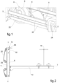
figure 1 is a perspective view, in a closed configuration, of an underride guard mounted to an industrial vehicle, according to an embodiment of the present invention; -
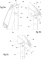
figure 2 is a side view, in the configuration of use, of the underride guard infigure 1 ; -
figure 3 is a partial view of the underride guard infigure 1 with separated parts; -
figure 4 is a side view of the enlarged detail IV indicated infigure 2 ; -
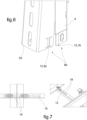
figures 5a, 5b, 5c are side views of the subsequent steps of opening the underride guard infigure 1 ; -
figure 6 is a perspective view of the enlarged detail VI indicated infigure 3 ; -
figures 7-8 are perspective views, from different angles, of the enlarged detail VII indicated infigure 3 ; -
figure 9 shows a step of closing an underride guard, according to a further embodiment of the present invention. - The elements or parts of elements common to the embodiments described below will be indicated using the same reference numerals.
- With reference to the aforementioned figures,
reference numeral 4 indicates as a whole an underride guard forvehicles 6 according to the present invention. - The
underride guard 4 comprises at least one upright 8 and, preferably, a pair ofuprights 8, directed along a vertical direction Y-Y, each upright 8 being provided with at least onebracket 12 for the connection with aframe 16 of anassociable vehicle 6. - In particular, said
uprights 8 are mutually spaced apart along a longitudinal direction X-X, perpendicular to said vertical direction Y-Y. - It is also possible to provide the
underride guard 4 connected to theframe 16 of thevehicle 6 by means of three or more uprights; in general, the number ofuprights 8 depends on the longitudinal length of theunderride guard 4. - The
underride guard 4 further comprises apartition 20 extending parallel to said longitudinal direction X-X, cantilevered between said pair ofuprights 8. - The partition typically comprises a hollow or honeycomb structure, e.g., made of metal and/or plastic material.
- According to an embodiment, the
bracket 12 for the connection with theframe 16 comprises a plurality of adjustment holes orslots 18 for varying the position of thepartition 20 with respect to theframe 16 in the vertical direction Y-Y and/or in the transverse direction T-T, perpendicular to the longitudinal direction X-X and the vertical direction Y-Y. - The
partition 20 has the function of preventing a cycle from accessing the cantilevered portion between a pair ofaxles vehicle 6. - Therefore, the partition is sized and shaped, according to regulations, so as to receive an impact from a potential cycle and not deform and/or cause damage to the cycle driver, in a known manner.
- For example, the
partition 20 is a chamfered or rounded box-like element. - The
partition 20 is provided, at each upright 8, with avertical leg 28 hinged to the corresponding upright 8 by means of anupper pin 32, arranged at anupper end 36 of the upright 8 itself. - The
partition 20 is rotatable from a use or lowered configuration, in which eachvertical leg 28 at least partially overlaps and is parallel to the corresponding upright 8, to a non-use or raised configuration, in which eachvertical leg 28 identifies, with the corresponding upright, an angle α greater than 90°. - Moreover, each
vertical leg 28 is provided with apeg 40 parallel to said longitudinal direction X-X and each upright 8 is provided with alower slot 44 and anupper recess 48 arranged opposite to thelower slot 44 with respect to theupper pin 32. - The
lower slot 44 has an arc-of-a-circle shape with respect to theupper pin 32 and is sized so as to accommodate saidpeg 40 and form an end-of-stroke for the rotation of thepartition 20 in the lowered configuration. - The
upper recess 48 is sized so as to form a stop of thepeg 40 in the raised configuration of thepartition 20. - Preferably, the
upper recess 48 is misaligned by aneccentricity 52 with respect to theupper pin 32 along a transverse direction T-T, perpendicular to the longitudinal direction X-X and the vertical direction Y-Y, approaching thepartition 20. - According to an embodiment, the
upper recess 48 is arranged above theupper pin 32, along said vertical direction Y-Y. - According to an embodiment, the
upper pin 32 is fastened on the respective upright 8 and is engaged on anupper slot 56 obtained on the correspondingvertical leg 28 so as to allow a relative movement between thepartition 20 and theuprights 8, along saidupper slot 56. - According to an embodiment, the upright 8 and the
vertical leg 28 have a pair oflocking holes 60 which are aligned in the use or lowered configuration; preferably asafety pin 64 is provided, which engages bothlocking holes 60 so as to ensure the locking of thepartition 20 in the lowered configuration (typically while the vehicle is traveling). - Preferably, the
vertical leg 28 and the upright 8, at mutuallower ends 68, have snap coupling means 72, which are engaged when thepartition 20 is in the use or lowered position. - According to an embodiment (
figure 6 ), said snap coupling means 72 comprise a flexible tab 76 and a slit 80 adapted to receive said flexible tab 76 in a coupling manner. - According to a further possible embodiment (
figure 9 ), said snap coupling means 72 comprise a leg 84 and at least one pair of flexible flaps 88 configured to achieve a snap coupling with an outer side wall of said leg 84. - For example, said flexible flaps 88 comprise a lead-in
portion 92 having a smaller width and a stop portion 96 having a greater width, which are mutually contiguous. - For example, said flexible flaps 88 each have a rear notch or slit 100 on the side opposite to the associable leg 84, to increase the flexibility thereof.
- The operation of an underride guard according to the present invention will now be described.
- In particular, the
underride guard 4 is initially in the lowered position, whereby the upright 8 and thevertical leg 28 are substantially overlapped and mutually aligned (therefore, the angle α is zero). In such a configuration, thesafety pin 64 can or cannot be provided inside therespective locking holes 60. - Regardless of the
safety pin 60, if any, the snap coupling means 72 are mutually engaged; they can include both the flexible tab 76 engaged in the corresponding slot 80 and the flexible flaps 88 engaged on the leg 84. - The operator lifts the
partition 20 by imposing an upward rotation around theupper pins 32. Thepeg 40 thus rotates out of thelower slot 44 and moves to a raised position until it rests against theupper recess 48. In this position, thepartition 20 is stable in the raised position. - Such a movement is also allowed by the relative sliding of
upper pin 32 with respect toupper slot 56. - The aforesaid sequence is reversed to return the partition to the lowered position, taking care to initially disengage the
peg 40 from theupper recess 48 by slightly retracting thevertical leg 28 with respect to theupper pin 32 by virtue of the sliding of saidupper pin 32 along theupper slot 56. - As can be appreciated from the above description, the present invention allows overcoming the drawbacks presented in the prior art.
- In particular, the underride guard is particularly easy to unlock and lock; in particular, the underride guard, although of extensive longitudinal dimensions, can be moved easily by a single operator.
- At the same time, the underride guard is locked and unlocked securely at all times, with no risk of vibration or noise while the vehicle is traveling.
- In particular, the snap coupling means prevent the occurrence of vibration while the vehicle is traveling.
- Moreover, the closed or locked condition is advantageously accompanied by a typical "click" which assures the user that he/she has correctly placed the partition back to the rest position. The user is thus always guaranteed to have properly locked the partition, even without the need to use the typical safety pin of the prior art solutions.
- Those skilled in the art may make several changes and variations to the solutions described above.
- The scope of protection of the invention is defined by the following claims.
Claims (9)
- An underride guard (4) comprising:- a pair of uprights (8), directed along a vertical direction (Y-Y), each upright (8) being provided with at least one bracket (12) for the connection with a frame (16) of an associable vehicle (6), said uprights (8) being mutually spaced apart in a longitudinal direction (X-X), perpendicular to said vertical direction (Y-Y),- a partition (20) extending parallel to said longitudinal direction (X-X), cantilevered between said pair of uprights (8), the partition (20) being provided, at each upright (8), with a vertical leg (28) hinged to the corresponding upright (8) by means of an upper pin (32), at an upper end (36) of the upright (8) itself,- the partition (20) being rotatable from a use or lowered configuration, in which each vertical leg (28) at least partially overlaps and is parallel to the corresponding upright (8), to a non-use or raised configuration, in which each vertical leg (28) identifies, with the corresponding upright (8), an angle (α) greater than 90°,- wherein each vertical leg (28) is provided with a peg (40) parallel to said longitudinal direction (X-X) and each upright (8) is provided with a lower slot (44) and an upper recess (48) arranged opposite to the lower slot (44) with respect to the upper pin (32),- wherein the lower slot (44) has an arc-of-a-circle shape with respect to the upper pin (32) and is sized so as to accommodate said peg (40) and form an end-of-stroke for the rotation of the partition (20) in the lowered configuration,- wherein the upper recess (48) is sized so as to form a stop of the peg (40) in the raised configuration of the partition (20),wherein the vertical leg (28) and the upright (8), at mutual lower ends (68), have snap coupling means (72) which are engaged when the partition (20) is in the use or lowered position.
- An underride guard (4) according to claim 1, wherein the upper recess (48) is misaligned by an eccentricity with respect to the upper pin (32) along a transverse direction (T-T), perpendicular to the longitudinal direction (X-X) and the vertical direction (Y-Y), approaching the partition (20).
- An underride guard (4) according to claim 1 or 2, wherein the upper recess (48) is arranged above the upper pin (32), along said vertical direction (Y-Y).
- An underride guard (4) according to claim 1, 2 or 3, wherein the upper pin (32) is fastened on the respective upright (8) and is engaged on an upper slot (56) obtained on the corresponding vertical leg (28) so as to allow a relative movement between the partition (20) and the uprights (8), along said upper slot (56).
- An underride guard (4) according to any one of claims 1 to 4, wherein said snap coupling means (72) comprise a flexible tab (76) and a slit (80) adapted to receive said flexible tab (76) in a coupling manner.
- An underride guard (4) according to any one of claims 1 to 5, wherein said snap coupling means (72) comprise a leg (84) and at least one pair of flexible flaps (88) configured to achieve a snap coupling with an outer side wall of said leg (84).
- An underride guard (4) according to claim 6, wherein said flexible flaps (88) comprise a lead-in portion (92) having a smaller width and a stop portion (96) having a greater width, which are mutually contiguous.
- An underride guard (4) according to claim 6 or 7, wherein said flexible flaps (88) each have a rear notch or slit (100) on the side opposite to the associable leg (84), to increase the flexibility thereof.
- An underride guard (4) according to any one of claims 1 to 8, wherein the bracket (12) for the connection with the frame (16) comprises a plurality of adjustment holes or slots (18) for varying the position of the partition (20) with respect to the frame (16) in the vertical direction (Y-Y) and/or in the transverse direction (T-T), perpendicular to the longitudinal direction (X-X) and the vertical direction (Y-Y).
Applications Claiming Priority (1)
| Application Number | Priority Date | Filing Date | Title |
|---|---|---|---|
| IT102023000010962A IT202300010962A1 (en) | 2023-05-30 | 2023-05-30 | PARACYCLES FOR VEHICLES |
Publications (2)
| Publication Number | Publication Date |
|---|---|
| EP4470846A1 true EP4470846A1 (en) | 2024-12-04 |
| EP4470846B1 EP4470846B1 (en) | 2025-12-24 |
Family
ID=87889470
Family Applications (1)
| Application Number | Title | Priority Date | Filing Date |
|---|---|---|---|
| EP24176262.4A Active EP4470846B1 (en) | 2023-05-30 | 2024-05-16 | Underride guard for vehicles |
Country Status (3)
| Country | Link |
|---|---|
| EP (1) | EP4470846B1 (en) |
| IT (1) | IT202300010962A1 (en) |
| PT (1) | PT4470846T (en) |
Citations (4)
| Publication number | Priority date | Publication date | Assignee | Title |
|---|---|---|---|---|
| EP1900575B1 (en) * | 2006-09-06 | 2010-04-07 | Takler S.r.l. | Safety bar, particulary for industrial vehicles |
| FR3017578A1 (en) * | 2014-02-17 | 2015-08-21 | Jetline | DEVICE FOR THE RETRACTION AND MECHANICAL FOLDING OF SIDE PROTECTIVE BARS MOUNTED ON ROAD TRUCKS |
| US9694776B2 (en) * | 2015-08-06 | 2017-07-04 | Oshkosh Corporation | Lateral access limitation system for a vehicle |
| EP3323681A1 (en) * | 2016-11-22 | 2018-05-23 | Takler S.r.l. | Supporting device for lateral protection elements for vehicles |
-
2023
- 2023-05-30 IT IT102023000010962A patent/IT202300010962A1/en unknown
-
2024
- 2024-05-16 EP EP24176262.4A patent/EP4470846B1/en active Active
- 2024-05-16 PT PT241762624T patent/PT4470846T/en unknown
Patent Citations (4)
| Publication number | Priority date | Publication date | Assignee | Title |
|---|---|---|---|---|
| EP1900575B1 (en) * | 2006-09-06 | 2010-04-07 | Takler S.r.l. | Safety bar, particulary for industrial vehicles |
| FR3017578A1 (en) * | 2014-02-17 | 2015-08-21 | Jetline | DEVICE FOR THE RETRACTION AND MECHANICAL FOLDING OF SIDE PROTECTIVE BARS MOUNTED ON ROAD TRUCKS |
| US9694776B2 (en) * | 2015-08-06 | 2017-07-04 | Oshkosh Corporation | Lateral access limitation system for a vehicle |
| EP3323681A1 (en) * | 2016-11-22 | 2018-05-23 | Takler S.r.l. | Supporting device for lateral protection elements for vehicles |
Also Published As
| Publication number | Publication date |
|---|---|
| EP4470846B1 (en) | 2025-12-24 |
| IT202300010962A1 (en) | 2024-11-30 |
| PT4470846T (en) | 2026-03-24 |
Similar Documents
| Publication | Publication Date | Title |
|---|---|---|
| US8919853B2 (en) | Integrated step and grab-handle system for tailgates | |
| JP3577520B2 (en) | Automotive hood hinges | |
| CA3007943C (en) | Tonneau cover striker assembly | |
| EP2686201B1 (en) | Vehicle seat | |
| US20100164196A1 (en) | Telescoping Vehicle Step | |
| US20200331714A1 (en) | Dock Restraint With Dynamic Offset Hook Assembly | |
| EP4470846A1 (en) | Underride guard for vehicles | |
| CA2916733C (en) | Loading dock locking system | |
| US20060097526A1 (en) | Rotating front bumper | |
| US5718019A (en) | Hinge device | |
| US12590479B2 (en) | Door latch device for vehicle | |
| US5562177A (en) | Vehicle anti-theft system | |
| US20230331314A1 (en) | Hideaway headache rack | |
| CN115279651A (en) | Tailgate for a vehicle with integrated folding door | |
| EP2619033B1 (en) | Fall-preventing system, particularly for vehicle- transporting trucks | |
| CN112654534B (en) | Device for attaching a trim part to a motor vehicle body structure such as a window pillar | |
| JP2020040527A (en) | Support structure of underrun protector | |
| KR102251713B1 (en) | Storage device, in particular for vehicle dashboard and corresponding vehicle | |
| US2958543A (en) | Tow guard for trucks or other vehicles | |
| CN223791274U (en) | All-terrain vehicle | |
| US6901780B1 (en) | Steering wheel and seat security lock | |
| EP4112378B1 (en) | A kit comprising a multiple support device for wheel chocks and at least one wheel chock | |
| EP4331912B1 (en) | Fall-proof system and motor-vehicle transporter equipped with such fall-proof system | |
| EP4570599A1 (en) | Bumper structure for a motor vehicle | |
| ES3054929T3 (en) | Protective device for a railway vehicle |
Legal Events
| Date | Code | Title | Description |
|---|---|---|---|
| PUAI | Public reference made under article 153(3) epc to a published international application that has entered the european phase |
Free format text: ORIGINAL CODE: 0009012 |
|
| STAA | Information on the status of an ep patent application or granted ep patent |
Free format text: STATUS: THE APPLICATION HAS BEEN PUBLISHED |
|
| AK | Designated contracting states |
Kind code of ref document: A1 Designated state(s): AL AT BE BG CH CY CZ DE DK EE ES FI FR GB GR HR HU IE IS IT LI LT LU LV MC ME MK MT NL NO PL PT RO RS SE SI SK SM TR |
|
| STAA | Information on the status of an ep patent application or granted ep patent |
Free format text: STATUS: REQUEST FOR EXAMINATION WAS MADE |
|
| 17P | Request for examination filed |
Effective date: 20250328 |
|
| GRAP | Despatch of communication of intention to grant a patent |
Free format text: ORIGINAL CODE: EPIDOSNIGR1 |
|
| STAA | Information on the status of an ep patent application or granted ep patent |
Free format text: STATUS: GRANT OF PATENT IS INTENDED |
|
| INTG | Intention to grant announced |
Effective date: 20250901 |
|
| GRAS | Grant fee paid |
Free format text: ORIGINAL CODE: EPIDOSNIGR3 |
|
| GRAA | (expected) grant |
Free format text: ORIGINAL CODE: 0009210 |
|
| STAA | Information on the status of an ep patent application or granted ep patent |
Free format text: STATUS: THE PATENT HAS BEEN GRANTED |
|
| AK | Designated contracting states |
Kind code of ref document: B1 Designated state(s): AL AT BE BG CH CY CZ DE DK EE ES FI FR GB GR HR HU IE IS IT LI LT LU LV MC ME MK MT NL NO PL PT RO RS SE SI SK SM TR |
|
| REG | Reference to a national code |
Ref country code: CH Ref legal event code: F10 Free format text: ST27 STATUS EVENT CODE: U-0-0-F10-F00 (AS PROVIDED BY THE NATIONAL OFFICE) Effective date: 20251224 Ref country code: GB Ref legal event code: FG4D |
|
| REG | Reference to a national code |
Ref country code: DE Ref legal event code: R096 Ref document number: 602024001797 Country of ref document: DE |
|
| REG | Reference to a national code |
Ref country code: PT Ref legal event code: SC4A Ref document number: 4470846 Country of ref document: PT Date of ref document: 20260324 Kind code of ref document: T Free format text: AVAILABILITY OF NATIONAL TRANSLATION Effective date: 20260318 |
|
| REG | Reference to a national code |
Ref country code: NL Ref legal event code: FP |
|
| REG | Reference to a national code |
Ref country code: LT Ref legal event code: MG9D |
|
| PG25 | Lapsed in a contracting state [announced via postgrant information from national office to epo] |
Ref country code: NO Free format text: LAPSE BECAUSE OF FAILURE TO SUBMIT A TRANSLATION OF THE DESCRIPTION OR TO PAY THE FEE WITHIN THE PRESCRIBED TIME-LIMIT Effective date: 20260324 |
|
| PG25 | Lapsed in a contracting state [announced via postgrant information from national office to epo] |
Ref country code: FI Free format text: LAPSE BECAUSE OF FAILURE TO SUBMIT A TRANSLATION OF THE DESCRIPTION OR TO PAY THE FEE WITHIN THE PRESCRIBED TIME-LIMIT Effective date: 20251224 Ref country code: HR Free format text: LAPSE BECAUSE OF FAILURE TO SUBMIT A TRANSLATION OF THE DESCRIPTION OR TO PAY THE FEE WITHIN THE PRESCRIBED TIME-LIMIT Effective date: 20251224 |
|
| PG25 | Lapsed in a contracting state [announced via postgrant information from national office to epo] |
Ref country code: RS Free format text: LAPSE BECAUSE OF FAILURE TO SUBMIT A TRANSLATION OF THE DESCRIPTION OR TO PAY THE FEE WITHIN THE PRESCRIBED TIME-LIMIT Effective date: 20260324 |
|
| PG25 | Lapsed in a contracting state [announced via postgrant information from national office to epo] |
Ref country code: LV Free format text: LAPSE BECAUSE OF FAILURE TO SUBMIT A TRANSLATION OF THE DESCRIPTION OR TO PAY THE FEE WITHIN THE PRESCRIBED TIME-LIMIT Effective date: 20251224 |