EP4470845A1 - Vehicle collision detection apparatus - Google Patents
Vehicle collision detection apparatus Download PDFInfo
- Publication number
- EP4470845A1 EP4470845A1 EP24174547.0A EP24174547A EP4470845A1 EP 4470845 A1 EP4470845 A1 EP 4470845A1 EP 24174547 A EP24174547 A EP 24174547A EP 4470845 A1 EP4470845 A1 EP 4470845A1
- Authority
- EP
- European Patent Office
- Prior art keywords
- plate
- collision detection
- collision
- detection sensor
- absorber
- Prior art date
- Legal status (The legal status is an assumption and is not a legal conclusion. Google has not performed a legal analysis and makes no representation as to the accuracy of the status listed.)
- Pending
Links
- 238000001514 detection method Methods 0.000 title claims abstract description 97
- 239000006096 absorbing agent Substances 0.000 claims abstract description 56
- 230000003139 buffering effect Effects 0.000 claims abstract description 5
- 230000002787 reinforcement Effects 0.000 claims description 25
- 230000003014 reinforcing effect Effects 0.000 claims description 4
- 210000002414 leg Anatomy 0.000 description 36
- 239000000872 buffer Substances 0.000 description 3
- 230000005484 gravity Effects 0.000 description 3
- 238000010586 diagram Methods 0.000 description 2
- 210000003127 knee Anatomy 0.000 description 2
- 230000007257 malfunction Effects 0.000 description 2
- 230000004048 modification Effects 0.000 description 2
- 238000012986 modification Methods 0.000 description 2
- 239000004604 Blowing Agent Substances 0.000 description 1
- 230000000694 effects Effects 0.000 description 1
- 239000000463 material Substances 0.000 description 1
Images



Classifications
-
- B—PERFORMING OPERATIONS; TRANSPORTING
- B60—VEHICLES IN GENERAL
- B60R—VEHICLES, VEHICLE FITTINGS, OR VEHICLE PARTS, NOT OTHERWISE PROVIDED FOR
- B60R19/00—Wheel guards; Radiator guards, e.g. grilles; Obstruction removers; Fittings damping bouncing force in collisions
- B60R19/02—Bumpers, i.e. impact receiving or absorbing members for protecting vehicles or fending off blows from other vehicles or objects
- B60R19/48—Bumpers, i.e. impact receiving or absorbing members for protecting vehicles or fending off blows from other vehicles or objects combined with, or convertible into, other devices or objects, e.g. bumpers combined with road brushes, bumpers convertible into beds
- B60R19/483—Bumpers, i.e. impact receiving or absorbing members for protecting vehicles or fending off blows from other vehicles or objects combined with, or convertible into, other devices or objects, e.g. bumpers combined with road brushes, bumpers convertible into beds with obstacle sensors of electric or electronic type
-
- B—PERFORMING OPERATIONS; TRANSPORTING
- B60—VEHICLES IN GENERAL
- B60R—VEHICLES, VEHICLE FITTINGS, OR VEHICLE PARTS, NOT OTHERWISE PROVIDED FOR
- B60R21/00—Arrangements or fittings on vehicles for protecting or preventing injuries to occupants or pedestrians in case of accidents or other traffic risks
- B60R21/01—Electrical circuits for triggering passive safety arrangements, e.g. airbags, safety belt tighteners, in case of vehicle accidents or impending vehicle accidents
- B60R21/013—Electrical circuits for triggering passive safety arrangements, e.g. airbags, safety belt tighteners, in case of vehicle accidents or impending vehicle accidents including means for detecting collisions, impending collisions or roll-over
- B60R21/0136—Electrical circuits for triggering passive safety arrangements, e.g. airbags, safety belt tighteners, in case of vehicle accidents or impending vehicle accidents including means for detecting collisions, impending collisions or roll-over responsive to actual contact with an obstacle, e.g. to vehicle deformation, bumper displacement or bumper velocity relative to the vehicle
-
- B—PERFORMING OPERATIONS; TRANSPORTING
- B60—VEHICLES IN GENERAL
- B60R—VEHICLES, VEHICLE FITTINGS, OR VEHICLE PARTS, NOT OTHERWISE PROVIDED FOR
- B60R19/00—Wheel guards; Radiator guards, e.g. grilles; Obstruction removers; Fittings damping bouncing force in collisions
- B60R19/02—Bumpers, i.e. impact receiving or absorbing members for protecting vehicles or fending off blows from other vehicles or objects
- B60R19/18—Bumpers, i.e. impact receiving or absorbing members for protecting vehicles or fending off blows from other vehicles or objects characterised by the cross-section; Means within the bumper to absorb impact
- B60R2019/186—Additional energy absorbing means supported on bumber beams, e.g. cellular structures or material
- B60R2019/1873—Cellular materials
Definitions
- the present invention relates to a vehicle collision detection apparatus.
- a collision detection apparatus of Patent Document 1 includes an impact-absorbing portion that deforms when a vehicle collides and absorbs the impact, a collision-detecting portion that detects the collision by deforming when the vehicle collides, and a reinforcing portion that reinforces the rigidity of a lower portion of the collision-detecting portion.
- Patent Document 1 states that this configuration enables the collision detection apparatus to detect collisions while clearly distinguishing between a collision with a pedestrian and a collision with a small animal or the like.
- Patent Document 1 Since a small animal that collides with a vehicle is an elastic body and is soft, the force is not transmitted straight backward from the surface that came into contact with the vehicle, but is distributed radially backward. Patent Document 1 does not give consideration to the distribution of the force in the case of a collision with a small animal, and it is therefore difficult to consider that a difference in input can be clearly distinguished between a collision with a pedestrian and a collision with a small animal.
- the collision detection apparatus detects a collision and activates an airbag or a pop-up hood for pedestrian protection that are provided in a front section of the vehicle even in the case of a collision with a small animal, this will cause safety issues due to obstructing the driver's field of view, and also cause repair costs. Therefore, it is desirable that a collision is not detected and a detection sensor is not activated if the collision is with a small animal.
- the present invention aims to provide a vehicle collision detection apparatus capable of detecting a collision while clearly distinguishing between a collision with a pedestrian and a collision with a small animal.
- a representative configuration of a vehicle collision detection apparatus is characterized in that the vehicle collision detection apparatus includes: a collision detection sensor that is installed rearward of a front bumper of a vehicle and detects a collision as a result of a pressure being applied to the collision detection sensor; a support plate having a flat-plate shape, located rearward of the collision detection sensor, and supporting the collision detection sensor; an absorber that is located forward of the collision detection sensor and applies a pressure to the collision detection sensor when buffering an impact received from front via the front bumper; a first plate covering a front face of the absorber over an entire vertical range of the front face; and a second plate installed forward of the first plate and extending from a higher position than the first plate over a vertical range of the first plate.
- a vehicle collision detection apparatus capable of detecting a collision while clearly distinguishing between a collision with a pedestrian and a collision with a small animal.
- the vehicle collision detection apparatus includes: a collision detection sensor that is installed rearward of a front bumper of a vehicle and detects a collision as a result of a pressure being applied to the collision detection sensor; a support plate having a flat-plate shape, located rearward of the collision detection sensor, and supporting the collision detection sensor; an absorber that is located forward of the collision detection sensor and applies a pressure to the collision detection sensor when buffering an impact received from front via the front bumper; a first plate covering a front face of the absorber over an entire vertical range of the front face; and a second plate installed forward of the first plate and extending from a higher position than the first plate over a vertical range of the first plate.
- the legs of a pedestrian are similar to rigid bodies extending upward and downward.
- the second plate When colliding with a leg of a pedestrian, the second plate is pushed straight backward in the same posture although the second plate extends from a higher position than the first plate to the vertical range of the first plate.
- the first plate Pushed by the second plate, the first plate also pushes the absorber strongly backward. As a result, the absorber is completely crushed and serves as a buffer. At that time, the collision detection sensor is crushed and thus detects the collision.
- a small animal is similar to an elastic body, and the mass of the small animal is distributed above and below the center of the height of the front bumper.
- the second plate is located at a higher position than the first plate and is separated from the first plate. The second plate thus causes the mass distributed upward to flow backward. At this time, the second plate does not strongly push the first plate, the absorber is not crushed, and the collision detection sensor does not detect the collision.
- an ideal result is achieved in which a pedestrian protection pop-up hood operates if a collision occurs with a pedestrian, whereas the pedestrian protection pop-up hood does not operate if a collision occurs with a small animal.
- a lower end of the second plate is disposed on the first plate at a higher position than a center of the vertical range of the first plate, an upper end of the second plate is a free end, and a predetermined space is provided rearward of the second plate and above the first plate.
- the second plate is located on the first plate, and the upper end is a free end. Since a space is provided behind the second plate, the second plate is more likely to fall backward if a collision occurs with a small animal. Therefore, the force of the second plate pushing the first plate definitely weakens, and the absorber is not crushed. A malfunction in which the collision detection sensor detects a collision due to a small animal is avoided more reliably.
- the absorber has: a main body covered by the first plate; a first leg extending backward from the main body and in contact with the support plate; and a second leg extending backward from the main body below the first leg, and in contact with the support plate, the collision detection sensor is located between the first leg and the second leg of the absorber, the vehicle collision detection apparatus further includes a bumper reinforcement reinforcing the front bumper and located rearward of the support plate, the bumper reinforcement has a first protrusion protruding forward and in contact with the support plate, and a second protrusion protruding forward below the first protrusion and in contact with the support plate, the first leg of the absorber overlaps the first protrusion of the bumper reinforcement over a predetermined vertical range, and the second protrusion of the bumper reinforcement is in contact with the support plate below the second leg of the absorber.
- the bumper reinforcement stably receives the absorber via the support plate. It is therefore possible to more reliably ensure correct behavior in which the pedestrian protection pop-up hood operates if a collision occurs with a pedestrian, whereas the pedestrian detection sensor does not detect the collision if a collision occurs with a small animal.
- the collision detection sensor determines, when a collision occurs, whether or not the collision is with a pedestrian or a small animal without being affected by the ambient temperature.
- the vehicle collision detection apparatus further includes: a license plate disposed forward of the front bumper, wherein the second plate is fixed to an upper end of the license plate with the front bumper therebetween.
- the second plate is pushed over a wide range due to the surface pressure of the license plate, which has a large area.
- FIG. 1 shows schematic views of a first example of a vehicle collision detection apparatus according to the present invention.
- FIGS. 1(a) and 1(c) are a front view and a plan view, respectively, of a vehicle collision detection apparatus 100
- FIG. 1(b) and 1(d) are a front view and a plan view, respectively, of the vehicle collision detection apparatus 100 shown in FIGS. 1(a) and 1(c) shown with a vehicle 102.
- FIG. 1 shows schematic views of a first example of a vehicle collision detection apparatus according to the present invention.
- FIGS. 1(a) and 1(c) are a front view and a plan view, respectively, of a vehicle collision detection apparatus 100
- FIG. 1(b) and 1(d) are a front view and a plan view, respectively, of the vehicle collision detection apparatus 100 shown in FIGS. 1(a) and 1(c) shown with a vehicle 102.
- FIG. 1 shows schematic views of a first example of a vehicle collision detection apparatus according to the present
- arrows F (Forward) and B (Backward) indicate the front and back directions with respect to the vehicle
- arrows L (Leftward) and R (Rightward) indicate the left and right in the vehicle width direction
- arrows U (Upward) and D (Downward) indicate the vertical direction.
- the vehicle collision detection apparatus 100 is disposed rearward of a front bumper 104 of the vehicle 102.
- the vehicle collision detection apparatus 100 includes a collision detection sensor tube 106, which is installed rearward of the front bumper 104 and detects a collision as a result of pressure being applied thereto.
- the collision detection sensor tube 106 may be a pressure sensor. When a predetermined pressure is detected, the collision detection sensor tube 106 regards the detected pressure as a collision and activates a pedestrian protection pop-up hood (not shown).
- FIG. 2 shows cross-sectional views of the vehicle collision detection apparatus 100 shown in FIGS. 1(a) and 1(c) , respectively.
- FIG. 2(a) is a perspective cross-sectional view
- FIG. 2(b) is a cross-sectional view of the vehicle 102 as seen from the left.
- the vehicle collision detection apparatus 100 includes a support plate 108, which is a flat-plate member located rearward of the collision detection sensor tube 106 and supports an absorber.
- the vehicle collision detection apparatus 100 includes an absorber 110, which is located forward of the collision detection sensor tube 106.
- the absorber 110 may use, for example, a blowing agent.
- the absorber 110 buffers the impact received from the front side via the front bumper 104 (see FIG. 1(d) ; not shown in FIG. 2 ), and crushes the collision detection sensor tube 106 at the time of the buffering.
- FIG. 1(c) explicitly shows the range in the vehicle width direction where the absorber 110 in FIG. 2(b) is installed
- the collision detection sensor tube 106 and the support plate 108 shown in FIG. 2(b) are also installed in substantially the same range in the vehicle width direction as the absorber 110.
- the vehicle collision detection apparatus 100 includes a first plate 120, which is bent so as to protrude forward and covers the front face of the absorber 110 over the entire vertical range thereof.
- the vehicle collision detection apparatus 100 also includes second plates 130A and 130B.
- the second plates 130A and 130B are also bent so as to protrude forward, and are installed forward of the first plate 120, extending from a higher position than the first plate 120 over an upper half of the first plate 120.
- all of the first plate 120 and the second plates 130A and 130B are located at the center of the vehicle 102 in the vehicle width direction, and are elongated in the vehicle width direction.
- the second plates 130A and 130B are installed with a gap therebetween in the vehicle width direction.
- first plate 120 and two second plates 130A and 130B are provided.
- the number of these plates may be one or more and may be any number as long as the positional relationship in which the second plates extend from a higher position than the first plate to the vertical range of the first plate is satisfied.
- the forward-protruding bent shape of the first plate 120 and the second plates 130A and 130B in this example is merely illustrative, and is not limited thereto as long as the above positional relationship is satisfied.
- FIG. 3 shows schematic diagrams illustrating how the force received from a colliding object is transmitted when the vehicle in FIG. 1 collides with the colliding object.
- FIG. 3(a) shows a case where a leg 132 of a pedestrian collides with the vehicle 102
- FIG. 3(b) shows a case where a small animal 142 collides with the vehicle 102.
- the figure on the left side of each of FIGS. 3(a) and 3(b) shows the moment when the colliding object and the vehicle 102 collide
- the figure on the right side is an enlarged view of the left figure and shows how the force applied from the colliding object to the vehicle 102 is transmitted at the time of the collision.
- the leg 132 of the pedestrian shown in FIG. 3(a) is similar to a rigid body extending upward and downward. As shown on the right side of FIG. 3(a) , a force 134 received directly by the vehicle when the vehicle collides with the leg 132 of the pedestrian is applied straight backward. Accordingly, forces 136 and 138 applied to the absorber 110 also become relatively large and are directed straight backward.
- the small animal 142 shown in FIG. 3(b) is similar to an elastic body.
- the area of contact with the front bumper 104 of the vehicle at the time of the collision with the vehicle 102 is also larger than in the case of the collision with the leg 132 of the pedestrian in FIG. 3(a) .
- forces 144, 146, and 148 that are directly received from the small animal 142 by the front bumper 104 of the vehicle 102 in the case of a collision with such a small animal are transmitted while being distributed vertically.
- the transmitted energy (force and mass) 150 and 152 is relatively small.
- the second plate 130A which extends from a position higher than the first plate 120 to the vertical range of the first plate 120, remains in the same posture and is pushed straight backward.
- the first plate 120 also crushes the absorber 110 backward.
- the absorber 110 is crushed and serves as a buffer over the vertical and longitudinal width of the first plate 120.
- pressure is applied to the collision detection sensor tube 106, thus detecting the collision.
- the second plate 130A which reaches a higher position than the first plate 120, distributes the force and is bent backward.
- the second plate 130A behaves such that an upper end 156 thereof rotates about a lower end 153 as a rotation axis.
- the first plate 120 overlapping the lower portion of the second plate 130A is hardly pushed by the second plate 130A, and the absorber 110 is therefore not crushed.
- Collision detection sensors disposed at respective ends of the collision detection sensor tube 106 do not detect a collision.
- the function of the second plate 130A is as follows. That is, when the leg of the pedestrian collides, the second plate 130A immediately transmits the force and crushes the absorber 110 and the collision detection sensor tube 106. That is, the second plate 130A eliminates the time lag between when the driver recognizes collision and when the brakes begin to work. Even when the leg inclines and moves into the second plate 130A, the second plate 130A transmits the force to the absorber 110 in a translational direction. This is because the collision detection sensor tube 106 cannot be effectively crushed if the absorber 110 is crushed from above. Furthermore, when a small animal collides, the second plate 130A disperses the mass thereof and reduces the translational force of the absorber 110.
- an ideal result can be achieved in which the pedestrian detection sensor detects a collision if a collision occurs with a pedestrian, and the pedestrian detection sensor does not detect a collision if a collision occurs with a small animal.
- the lower end 153 of the second plate 130A is disposed on the first plate 120 at a higher position than a center 154 of the vertical range of the first plate 120. Further, the upper end 156 of the second plate 130A is a free end and is not connected to any other member. Although not shown, the second plate 130A is fixed to the front bumper 104. A predetermined space 160 is provided rearward of the second plate 130A and above the first plate 120.
- the second plate 130A in FIG. 2(b) is disposed on the first plate 120, and the upper end 156 is a free end.
- the space 160 is provided behind the second plate 130A, the second plate 130A is more likely to bend backward if a collision occurs with the small animal 142. Therefore, the behavior in which the second plate 130A pushes the first plate 120 and crushes the absorber 110 is less likely to occur. That is, a malfunction in which the collision detection sensor tube 106 detects a collision due to a collision with a small animal is avoided more reliably.
- the absorber 110 includes a main body 110A, which is covered by the first plate 120, a first leg 110B extending backward from the main body 110A and in contact with the support plate 108, and a second leg 110C extending backward from the main body 110A below the first leg 110B and in contact with the support plate 108.
- the collision detection sensor tube 106 is located in a space 184 between the first leg 110B and second leg 110C of the absorber 110.
- a top face 110E of the main body 110A of the absorber 110 has a shape that is inclined downward while extending forward, and a lower face 110F has a shape that is inclined upward while extending forward, as seen from the vehicle width direction.
- the vehicle collision detection apparatus 100 also includes a bumper reinforcement 170 that reinforces the front bumper 104.
- the bumper reinforcement 170 is located rearward of the support plate 108.
- the bumper reinforcement 170 has a first protrusion 170A protruding forward and in contact with the support plate 108, and a second protrusion 170B protruding forward below the first protrusion 170A and in contact with the support plate 108.
- a recess 180 is formed between the first protrusion 170A and the second protrusion 170B.
- a reinforcing member 183 is also provided on the rear side of the bumper reinforcement 170.
- the first leg 110B of the absorber 110 and the first protrusion 170A of the bumper reinforcement 170 overlap over a predetermined vertical range.
- the second protrusion 170B of the bumper reinforcement 170 is in contact with the support plate 108 below the second leg 110C of the absorber 110. Therefore, the second leg 110C of the absorber 110 inevitably overlaps the recess 180 of the bumper reinforcement 170.
- both the second leg 110C of the absorber 110 and the recess 180 of the bumper reinforcement 170 overlap a center 182 of the vertical range of the bumper reinforcement 170. Note that the center 182 is set at an average knee height of a human (adult).
- the reason for thus setting the height is to bring the center 182 of the bumper reinforcement 170 as close as possible to the center of gravity of a pedestrian and accurately detect a collision with a pedestrian. Since the center of gravity of a pedestrian is approximately around the waist, the center 182 is set at the knee height of adults, and is set closer to the center of gravity (waist) for children.
- a sufficient space 184 is provided between the first leg 110B and the second leg 110C of the absorber 110.
- the collision detection sensor 106 determines, when a collision occurs, whether or not the collision is with a pedestrian or a small animal without being affected by the ambient temperature. Further, the amount of crushing of the absorber 110 can be controlled by the surface pressure applied by the first plate 120, and it is therefore possible to cope with changes caused by the ambient temperature.
- FIG. 4 illustrates a second example of the vehicle collision detection apparatus according to the present invention in correspondence with FIG. 2 .
- FIG. 4(a) is a perspective cross-sectional view of a vehicle collision detection apparatus 200 according to this example
- FIG. 4(b) is a cross-sectional view of the vehicle collision detection apparatus 200 as seen from the right side of vehicle 102.
- the same elements as those in the first example are assigned the same reference numerals, and the description thereof is omitted.
- the vehicle collision detection apparatus 200 differs from the vehicle collision detection apparatus 100 according to the first example with respect to the shape of an absorber 210.
- the absorber 210 is the same as the absorber 110 in that it has a main body 210A, a first leg 210B, and a second leg 210C, but is different from the absorber 110 in that it also has a third leg 210D.
- the third leg 210D overlaps the second protrusion 170B of the bumper reinforcement 170 over a predetermined vertical range with the support plate 108 therebetween.
- the vehicle collision detection apparatus 200 also includes a license plate 220 disposed forward of the front bumper 104. Note that the license plate 220 is omitted in FIG. 4 (a) . As shown in FIG. 4 (b) , the second plate 130A of the vehicle collision detection apparatus 200 is fixed to an upper end 220A of the license plate 220 with a grill 230 of the front bumper 104 therebetween, by a fixing member 232 such as a bolt.
- the second plate 130A is pushed over a wide range by the surface pressure of the license plate 220, which has a large area.
- the present invention is applicable to a vehicle collision detection apparatus.
Landscapes
- Engineering & Computer Science (AREA)
- Mechanical Engineering (AREA)
- Force Measurement Appropriate To Specific Purposes (AREA)
Abstract
[Object] Provided is a vehicle collision detection apparatus capable of detecting a collision while clearly distinguishing between a collision with a pedestrian and a collision with a small animal.
[Means to Solve the Problem] A vehicle collision detection apparatus (100) includes: a collision detection sensor (106) that is installed rearward of a front bumper (104) of a vehicle (102) and detects a collision as a result of a pressure being applied to the collision detection sensor (106); a support plate (108) having a flat-plate shape, located rearward of the collision detection sensor (106), and supporting the collision detection sensor (106); an absorber (110) that is located forward of the collision detection sensor (106) and applies a pressure to the collision detection sensor (106) when buffering an impact received from front via the front bumper (104); a first plate (120) covering a front face of the absorber (110) over an entire vertical range of the front face; and a second plate (130A, 130B) installed forward of the first plate (120) and extending from a higher position than the first plate (120) over a vertical range of the first plate (120).
Description
- The present invention relates to a vehicle collision detection apparatus.
- For example, a collision detection apparatus of Patent Document 1 includes an impact-absorbing portion that deforms when a vehicle collides and absorbs the impact, a collision-detecting portion that detects the collision by deforming when the vehicle collides, and a reinforcing portion that reinforces the rigidity of a lower portion of the collision-detecting portion. Patent Document 1 states that this configuration enables the collision detection apparatus to detect collisions while clearly distinguishing between a collision with a pedestrian and a collision with a small animal or the like.
- [Patent Document 1]
JP 2021-138184A - Since a small animal that collides with a vehicle is an elastic body and is soft, the force is not transmitted straight backward from the surface that came into contact with the vehicle, but is distributed radially backward. Patent Document 1 does not give consideration to the distribution of the force in the case of a collision with a small animal, and it is therefore difficult to consider that a difference in input can be clearly distinguished between a collision with a pedestrian and a collision with a small animal.
- If the collision detection apparatus detects a collision and activates an airbag or a pop-up hood for pedestrian protection that are provided in a front section of the vehicle even in the case of a collision with a small animal, this will cause safety issues due to obstructing the driver's field of view, and also cause repair costs. Therefore, it is desirable that a collision is not detected and a detection sensor is not activated if the collision is with a small animal.
- In view of the forgoing problem, the present invention aims to provide a vehicle collision detection apparatus capable of detecting a collision while clearly distinguishing between a collision with a pedestrian and a collision with a small animal.
- To solve the above-stated problem, a representative configuration of a vehicle collision detection apparatus according to the present invention is characterized in that the vehicle collision detection apparatus includes: a collision detection sensor that is installed rearward of a front bumper of a vehicle and detects a collision as a result of a pressure being applied to the collision detection sensor; a support plate having a flat-plate shape, located rearward of the collision detection sensor, and supporting the collision detection sensor; an absorber that is located forward of the collision detection sensor and applies a pressure to the collision detection sensor when buffering an impact received from front via the front bumper; a first plate covering a front face of the absorber over an entire vertical range of the front face; and a second plate installed forward of the first plate and extending from a higher position than the first plate over a vertical range of the first plate.
- According to the present invention, it is possible to provide a vehicle collision detection apparatus capable of detecting a collision while clearly distinguishing between a collision with a pedestrian and a collision with a small animal.
-
-
FIG. 1 shows front views and plan views of a first example of a vehicle collision detection apparatus according to the present invention. -
FIG. 2 shows cross-sectional views of the vehicle collision detection apparatus shown inFIGS. 1(a) and 1(c) each taken along a line A-A. -
FIG. 3 shows schematic diagrams illustrating how the force received from a colliding object is transmitted when the vehicle inFIG. 1 collides with the colliding object. -
FIG. 4 illustrates a second example of the vehicle collision detection apparatus according to the present invention in correspondence withFIG. 2 . - One embodiment of the vehicle collision detection apparatus according to the present invention is characterized in that the vehicle collision detection apparatus includes: a collision detection sensor that is installed rearward of a front bumper of a vehicle and detects a collision as a result of a pressure being applied to the collision detection sensor; a support plate having a flat-plate shape, located rearward of the collision detection sensor, and supporting the collision detection sensor; an absorber that is located forward of the collision detection sensor and applies a pressure to the collision detection sensor when buffering an impact received from front via the front bumper; a first plate covering a front face of the absorber over an entire vertical range of the front face; and a second plate installed forward of the first plate and extending from a higher position than the first plate over a vertical range of the first plate.
- The legs of a pedestrian are similar to rigid bodies extending upward and downward. When colliding with a leg of a pedestrian, the second plate is pushed straight backward in the same posture although the second plate extends from a higher position than the first plate to the vertical range of the first plate. Pushed by the second plate, the first plate also pushes the absorber strongly backward. As a result, the absorber is completely crushed and serves as a buffer. At that time, the collision detection sensor is crushed and thus detects the collision.
- In contrast, a small animal is similar to an elastic body, and the mass of the small animal is distributed above and below the center of the height of the front bumper. The second plate is located at a higher position than the first plate and is separated from the first plate. The second plate thus causes the mass distributed upward to flow backward. At this time, the second plate does not strongly push the first plate, the absorber is not crushed, and the collision detection sensor does not detect the collision.
- Therefore, according to the present invention, an ideal result is achieved in which a pedestrian protection pop-up hood operates if a collision occurs with a pedestrian, whereas the pedestrian protection pop-up hood does not operate if a collision occurs with a small animal.
- It is preferable that a lower end of the second plate is disposed on the first plate at a higher position than a center of the vertical range of the first plate, an upper end of the second plate is a free end, and a predetermined space is provided rearward of the second plate and above the first plate.
- According to this configuration, only the lower end of the second plate is located on the first plate, and the upper end is a free end. Since a space is provided behind the second plate, the second plate is more likely to fall backward if a collision occurs with a small animal. Therefore, the force of the second plate pushing the first plate definitely weakens, and the absorber is not crushed. A malfunction in which the collision detection sensor detects a collision due to a small animal is avoided more reliably.
- It is preferable that the absorber has: a main body covered by the first plate; a first leg extending backward from the main body and in contact with the support plate; and a second leg extending backward from the main body below the first leg, and in contact with the support plate, the collision detection sensor is located between the first leg and the second leg of the absorber, the vehicle collision detection apparatus further includes a bumper reinforcement reinforcing the front bumper and located rearward of the support plate, the bumper reinforcement has a first protrusion protruding forward and in contact with the support plate, and a second protrusion protruding forward below the first protrusion and in contact with the support plate, the first leg of the absorber overlaps the first protrusion of the bumper reinforcement over a predetermined vertical range, and the second protrusion of the bumper reinforcement is in contact with the support plate below the second leg of the absorber.
- According to this configuration, the bumper reinforcement stably receives the absorber via the support plate. It is therefore possible to more reliably ensure correct behavior in which the pedestrian protection pop-up hood operates if a collision occurs with a pedestrian, whereas the pedestrian detection sensor does not detect the collision if a collision occurs with a small animal.
- According to the above configuration, there is a sufficient space between the first leg and the second leg of the absorber. Thus, the collision detection sensor determines, when a collision occurs, whether or not the collision is with a pedestrian or a small animal without being affected by the ambient temperature.
- It is preferable that the vehicle collision detection apparatus further includes: a license plate disposed forward of the front bumper, wherein the second plate is fixed to an upper end of the license plate with the front bumper therebetween.
- According to this configuration, the second plate is pushed over a wide range due to the surface pressure of the license plate, which has a large area. This makes the distinction between the ON and OFF states clearer. That is, settings can be made so as to more accurately determine, when a collision occurs, whether the collision is with a pedestrian or is a minor collision with a small animal.
- Hereinafter, preferable examples of the present invention will be described in detail with reference to the attached drawings. Dimensions, materials, other specific values, and the like described in the examples are merely illustrative for facilitating understanding of the invention, and are not intended to limit the present invention unless stated otherwise. Note that in the present specification and drawings, elements having substantially the same function and configuration are assigned the same reference numerals to omit redundant descriptions, and elements that are not directly related to the present invention may be omitted in the drawings.
-
FIG. 1 shows schematic views of a first example of a vehicle collision detection apparatus according to the present invention.FIGS. 1(a) and 1(c) are a front view and a plan view, respectively, of a vehiclecollision detection apparatus 100, andFIG. 1(b) and 1(d) are a front view and a plan view, respectively, of the vehiclecollision detection apparatus 100 shown inFIGS. 1(a) and 1(c) shown with avehicle 102. InFIG. 1 and all of the other drawings, arrows F (Forward) and B (Backward) indicate the front and back directions with respect to the vehicle, arrows L (Leftward) and R (Rightward) indicate the left and right in the vehicle width direction, and arrows U (Upward) and D (Downward) indicate the vertical direction. - As shown in
FIG. 1(d) , the vehiclecollision detection apparatus 100 is disposed rearward of afront bumper 104 of thevehicle 102. The vehiclecollision detection apparatus 100 includes a collisiondetection sensor tube 106, which is installed rearward of thefront bumper 104 and detects a collision as a result of pressure being applied thereto. The collisiondetection sensor tube 106 may be a pressure sensor. When a predetermined pressure is detected, the collisiondetection sensor tube 106 regards the detected pressure as a collision and activates a pedestrian protection pop-up hood (not shown). -
FIG. 2 shows cross-sectional views of the vehiclecollision detection apparatus 100 shown inFIGS. 1(a) and 1(c) , respectively.FIG. 2(a) is a perspective cross-sectional view, andFIG. 2(b) is a cross-sectional view of thevehicle 102 as seen from the left. The vehiclecollision detection apparatus 100 includes asupport plate 108, which is a flat-plate member located rearward of the collisiondetection sensor tube 106 and supports an absorber. - As shown in
FIG. 2(b) , the vehiclecollision detection apparatus 100 includes anabsorber 110, which is located forward of the collisiondetection sensor tube 106. Theabsorber 110 may use, for example, a blowing agent. Theabsorber 110 buffers the impact received from the front side via the front bumper 104 (seeFIG. 1(d) ; not shown inFIG. 2 ), and crushes the collisiondetection sensor tube 106 at the time of the buffering. - Although
FIG. 1(c) explicitly shows the range in the vehicle width direction where theabsorber 110 inFIG. 2(b) is installed, the collisiondetection sensor tube 106 and thesupport plate 108 shown inFIG. 2(b) are also installed in substantially the same range in the vehicle width direction as theabsorber 110. - As shown in
FIG. 2(b) , the vehiclecollision detection apparatus 100 includes afirst plate 120, which is bent so as to protrude forward and covers the front face of theabsorber 110 over the entire vertical range thereof. - As shown in
FIGS. 1 and2 , the vehiclecollision detection apparatus 100 also includessecond plates second plates first plate 120, extending from a higher position than thefirst plate 120 over an upper half of thefirst plate 120. - As shown in
FIG. 1 , all of thefirst plate 120 and thesecond plates vehicle 102 in the vehicle width direction, and are elongated in the vehicle width direction. Thesecond plates - In this example, one
first plate 120 and twosecond plates first plate 120 and thesecond plates - Hereinafter, regarding the
second plates second plate 130A, but thesecond plate 130B also has the same configuration unless stated otherwise. -
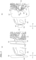
FIG. 3 shows schematic diagrams illustrating how the force received from a colliding object is transmitted when the vehicle inFIG. 1 collides with the colliding object.FIG. 3(a) shows a case where aleg 132 of a pedestrian collides with thevehicle 102, andFIG. 3(b) shows a case where asmall animal 142 collides with thevehicle 102. The figure on the left side of each ofFIGS. 3(a) and 3(b) shows the moment when the colliding object and thevehicle 102 collide, and the figure on the right side is an enlarged view of the left figure and shows how the force applied from the colliding object to thevehicle 102 is transmitted at the time of the collision. - The
leg 132 of the pedestrian shown inFIG. 3(a) is similar to a rigid body extending upward and downward. As shown on the right side ofFIG. 3(a) , aforce 134 received directly by the vehicle when the vehicle collides with theleg 132 of the pedestrian is applied straight backward. Accordingly,forces absorber 110 also become relatively large and are directed straight backward. - On the other hand, the
small animal 142 shown inFIG. 3(b) is similar to an elastic body. As shown on the right side ofFIG. 3(b) , the area of contact with thefront bumper 104 of the vehicle at the time of the collision with thevehicle 102 is also larger than in the case of the collision with theleg 132 of the pedestrian inFIG. 3(a) . Further, as shown on the right side ofFIG. 3(b) ,forces small animal 142 by thefront bumper 104 of thevehicle 102 in the case of a collision with such a small animal are transmitted while being distributed vertically. The transmitted energy (force and mass) 150 and 152 is relatively small. - Accordingly, when the vehicle
collision detection apparatus 100 inFIG. 2 collides with theleg 132 of the pedestrian, thesecond plate 130A, which extends from a position higher than thefirst plate 120 to the vertical range of thefirst plate 120, remains in the same posture and is pushed straight backward. Pushed by thesecond plate 130A, thefirst plate 120 also crushes theabsorber 110 backward. As a result, theabsorber 110 is crushed and serves as a buffer over the vertical and longitudinal width of thefirst plate 120. At this time, pressure is applied to the collisiondetection sensor tube 106, thus detecting the collision. - In contrast, when the vehicle
collision detection apparatus 100 inFIG. 2 receives the impact due to thesmall animal 142 or the like, according to this example, thesecond plate 130A, which reaches a higher position than thefirst plate 120, distributes the force and is bent backward. In other words, thesecond plate 130A behaves such that anupper end 156 thereof rotates about alower end 153 as a rotation axis. As a result, thefirst plate 120 overlapping the lower portion of thesecond plate 130A is hardly pushed by thesecond plate 130A, and theabsorber 110 is therefore not crushed. Collision detection sensors disposed at respective ends of the collisiondetection sensor tube 106 do not detect a collision. - The function of the
second plate 130A is as follows. That is, when the leg of the pedestrian collides, thesecond plate 130A immediately transmits the force and crushes theabsorber 110 and the collisiondetection sensor tube 106. That is, thesecond plate 130A eliminates the time lag between when the driver recognizes collision and when the brakes begin to work. Even when the leg inclines and moves into thesecond plate 130A, thesecond plate 130A transmits the force to theabsorber 110 in a translational direction. This is because the collisiondetection sensor tube 106 cannot be effectively crushed if theabsorber 110 is crushed from above. Furthermore, when a small animal collides, thesecond plate 130A disperses the mass thereof and reduces the translational force of theabsorber 110. - Therefore, according to this example, an ideal result can be achieved in which the pedestrian detection sensor detects a collision if a collision occurs with a pedestrian, and the pedestrian detection sensor does not detect a collision if a collision occurs with a small animal.
- As shown in
FIG. 2(b) , thelower end 153 of thesecond plate 130A is disposed on thefirst plate 120 at a higher position than acenter 154 of the vertical range of thefirst plate 120. Further, theupper end 156 of thesecond plate 130A is a free end and is not connected to any other member. Although not shown, thesecond plate 130A is fixed to thefront bumper 104. Apredetermined space 160 is provided rearward of thesecond plate 130A and above thefirst plate 120. - Thus, only the
lower end 153 of thesecond plate 130A inFIG. 2(b) is disposed on thefirst plate 120, and theupper end 156 is a free end. Further, since thespace 160 is provided behind thesecond plate 130A, thesecond plate 130A is more likely to bend backward if a collision occurs with thesmall animal 142. Therefore, the behavior in which thesecond plate 130A pushes thefirst plate 120 and crushes theabsorber 110 is less likely to occur. That is, a malfunction in which the collisiondetection sensor tube 106 detects a collision due to a collision with a small animal is avoided more reliably. - As shown in
FIG. 2(b) , theabsorber 110 includes amain body 110A, which is covered by thefirst plate 120, afirst leg 110B extending backward from themain body 110A and in contact with thesupport plate 108, and a second leg 110C extending backward from themain body 110A below thefirst leg 110B and in contact with thesupport plate 108. The collisiondetection sensor tube 106 is located in aspace 184 between thefirst leg 110B and second leg 110C of theabsorber 110. - As shown in
FIG. 2(b) , atop face 110E of themain body 110A of theabsorber 110 has a shape that is inclined downward while extending forward, and alower face 110F has a shape that is inclined upward while extending forward, as seen from the vehicle width direction. - As shown in
FIG. 2(b) , the vehiclecollision detection apparatus 100 also includes abumper reinforcement 170 that reinforces thefront bumper 104. Thebumper reinforcement 170 is located rearward of thesupport plate 108. Thebumper reinforcement 170 has afirst protrusion 170A protruding forward and in contact with thesupport plate 108, and asecond protrusion 170B protruding forward below thefirst protrusion 170A and in contact with thesupport plate 108. Arecess 180 is formed between thefirst protrusion 170A and thesecond protrusion 170B. Note that a reinforcingmember 183 is also provided on the rear side of thebumper reinforcement 170. - As shown in
FIG. 2 , thefirst leg 110B of theabsorber 110 and thefirst protrusion 170A of thebumper reinforcement 170 overlap over a predetermined vertical range. Thesecond protrusion 170B of thebumper reinforcement 170 is in contact with thesupport plate 108 below the second leg 110C of theabsorber 110. Therefore, the second leg 110C of theabsorber 110 inevitably overlaps therecess 180 of thebumper reinforcement 170. In this example, both the second leg 110C of theabsorber 110 and therecess 180 of thebumper reinforcement 170 overlap acenter 182 of the vertical range of thebumper reinforcement 170. Note that thecenter 182 is set at an average knee height of a human (adult). The reason for thus setting the height is to bring thecenter 182 of thebumper reinforcement 170 as close as possible to the center of gravity of a pedestrian and accurately detect a collision with a pedestrian. Since the center of gravity of a pedestrian is approximately around the waist, thecenter 182 is set at the knee height of adults, and is set closer to the center of gravity (waist) for children. - That is, according to this example, even if a collision occurs with a small animal at a relatively low position, e.g. at a lower position than the
center 154 of the vertical range of thefirst plate 120, it can be correctly determined that a collision has occurred with a small animal, and the correct behavior in which the pedestrian protection pop-up hood does not operate can be ensured more reliably. - According to this example, a
sufficient space 184 is provided between thefirst leg 110B and the second leg 110C of theabsorber 110. Thus, thecollision detection sensor 106 determines, when a collision occurs, whether or not the collision is with a pedestrian or a small animal without being affected by the ambient temperature. Further, the amount of crushing of theabsorber 110 can be controlled by the surface pressure applied by thefirst plate 120, and it is therefore possible to cope with changes caused by the ambient temperature. -
FIG. 4 illustrates a second example of the vehicle collision detection apparatus according to the present invention in correspondence withFIG. 2 .FIG. 4(a) is a perspective cross-sectional view of a vehiclecollision detection apparatus 200 according to this example, andFIG. 4(b) is a cross-sectional view of the vehiclecollision detection apparatus 200 as seen from the right side ofvehicle 102. In this example as well, the same elements as those in the first example are assigned the same reference numerals, and the description thereof is omitted. - As shown in
FIG. 4 , the vehiclecollision detection apparatus 200 according to the second example differs from the vehiclecollision detection apparatus 100 according to the first example with respect to the shape of anabsorber 210. Theabsorber 210 is the same as theabsorber 110 in that it has amain body 210A, afirst leg 210B, and a second leg 210C, but is different from theabsorber 110 in that it also has athird leg 210D. Thethird leg 210D overlaps thesecond protrusion 170B of thebumper reinforcement 170 over a predetermined vertical range with thesupport plate 108 therebetween. - The vehicle
collision detection apparatus 200 also includes alicense plate 220 disposed forward of thefront bumper 104. Note that thelicense plate 220 is omitted inFIG. 4 (a) . As shown inFIG. 4 (b) , thesecond plate 130A of the vehiclecollision detection apparatus 200 is fixed to anupper end 220A of thelicense plate 220 with agrill 230 of thefront bumper 104 therebetween, by a fixingmember 232 such as a bolt. - According to this configuration of the second example, the
second plate 130A is pushed over a wide range by the surface pressure of thelicense plate 220, which has a large area. This makes the distinction between the ON and OFF states clearer. That is, settings can be made so as to more accurately determine whether a collision is with a pedestrian or is a minor collision with a small animal. - Although a preferable embodiment of the present invention has been described above with reference to the attached drawings, the present invention is, needless to say, not limited to the above-described example. It is apparent that a person skilled in the art may conceive various modifications and variations within the scope of the appended patent claims, and those modifications and variations should be understood to be naturally encompassed in the technical scope of the present invention.
- For the present invention, the inventions described in the claims and the examples can be freely combined for implementation, regardless of the dependency of the claims.
- The present invention is applicable to a vehicle collision detection apparatus.
- 100, 200 ... vehicle collision detection apparatus; 102 ... Vehicle; 104 ... Front bumper; 106 ... Collision detection sensor (tube); 108 ... Support plate; 110, 210 ... Absorber; 110A ... Main body of absorber; 110B ... First leg of absorber; 110C ... Second leg of absorber; 120 ... First plate; 130A, 130B ... Second plate; 132 ... Leg of pedestrian; 142 ... Small animal; 160 ... Space; 170 ... Bumper reinforcement; 170A ... First protrusion of bumper reinforcement; 170B ... Second protrusion of bumper reinforcement; 180 ... Recess of bumper reinforcement; 220 ... License plate; 230 ... Grill
Claims (4)
- A vehicle collision detection apparatus (100, 200) comprising:a collision detection sensor (106) that is installed rearward of a front bumper (104) of a vehicle (102) and detects a collision as a result of a pressure being applied to the collision detection sensor (106);a support plate (108) having a flat-plate shape, located rearward of the collision detection sensor (106), and supporting the collision detection sensor (106);an absorber (110, 210) that is located forward of the collision detection sensor (106) and applies a pressure to the collision detection sensor (106) when buffering an impact received from front via the front bumper (104);a first plate (120) covering a front face of the absorber (110, 210) over an entire vertical range of the front face; anda second plate (130A, 130B) installed forward of the first plate (120) and extending from a higher position than the first plate (120) over a vertical range of the first plate (120) .
- The vehicle collision detection apparatus (100, 200) according to claim 1,wherein a lower end of the second plate (130A, 130B) is disposed on the first plate (120) at a higher position than a center of the vertical range of the first plate (120),an upper end of the second plate (130A, 130B) is a free end, anda predetermined space (160) is provided rearward of the second plate (130A, 130B) and above the first plate (120).
- The vehicle collision detection apparatus (100, 200) according to claim 2,wherein the absorber (110, 210) has:a main body (110A) covered by the first plate (120) ;a first leg (110B) extending backward from the main body (110A) and in contact with the support plate (108); anda second leg (110C) extending backward from the main body (110A) below the first leg (110B), and in contact with the support plate (108),the collision detection sensor (106) is located between the first leg (110B) and the second leg (110C) of the absorber (110, 210),the vehicle collision detection apparatus (100, 200) further comprises a bumper reinforcement (170) reinforcing the front bumper (104) and located rearward of the support plate (108),the bumper reinforcement (170) has a first protrusion (170A) protruding forward and in contact with the support plate (108), and a second protrusion (170B) protruding forward below the first protrusion (170A) and in contact with the support plate (108),the first leg (110B) of the absorber (110, 210) overlaps the first protrusion (170A) of the bumper reinforcement (170) over a predetermined vertical range, andthe second protrusion (170B) of the bumper reinforcement (170) is in contact with the support plate (108) below the second leg (110C) of the absorber (110, 210).
- The vehicle collision detection apparatus (100, 200) according to claim 2 or 3, further comprising:a license plate (220) disposed forward of the front bumper (104),wherein the second plate (130A, 130B) is fixed to an upper end of the license plate (220) with the front bumper (104) therebetween.
Applications Claiming Priority (1)
| Application Number | Priority Date | Filing Date | Title |
|---|---|---|---|
| JP2023087447A JP2024170753A (en) | 2023-05-29 | 2023-05-29 | Vehicle collision detection device |
Publications (1)
| Publication Number | Publication Date |
|---|---|
| EP4470845A1 true EP4470845A1 (en) | 2024-12-04 |
Family
ID=91029908
Family Applications (1)
| Application Number | Title | Priority Date | Filing Date |
|---|---|---|---|
| EP24174547.0A Pending EP4470845A1 (en) | 2023-05-29 | 2024-05-07 | Vehicle collision detection apparatus |
Country Status (2)
| Country | Link |
|---|---|
| EP (1) | EP4470845A1 (en) |
| JP (1) | JP2024170753A (en) |
Citations (6)
| Publication number | Priority date | Publication date | Assignee | Title |
|---|---|---|---|---|
| WO2016092793A1 (en) * | 2014-12-10 | 2016-06-16 | 株式会社デンソー | Vehicle collision detecting device |
| US9676354B2 (en) * | 2015-03-11 | 2017-06-13 | Toyota Jidosha Kabushiki Kaisha | Bumper absorber structure |
| US9802563B2 (en) * | 2016-02-08 | 2017-10-31 | Toyota Jidosha Kabushiki Kaisha | Vehicle front portion structure provided with a pedestrian collision detection sensor |
| JP2018167695A (en) * | 2017-03-29 | 2018-11-01 | 株式会社Subaru | Vehicle collision determination device |
| JP2021138182A (en) * | 2020-03-02 | 2021-09-16 | 株式会社Subaru | Collision detection device |
| JP2021138184A (en) | 2020-03-02 | 2021-09-16 | 株式会社Subaru | Collision detection device |
-
2023
- 2023-05-29 JP JP2023087447A patent/JP2024170753A/en active Pending
-
2024
- 2024-05-07 EP EP24174547.0A patent/EP4470845A1/en active Pending
Patent Citations (6)
| Publication number | Priority date | Publication date | Assignee | Title |
|---|---|---|---|---|
| WO2016092793A1 (en) * | 2014-12-10 | 2016-06-16 | 株式会社デンソー | Vehicle collision detecting device |
| US9676354B2 (en) * | 2015-03-11 | 2017-06-13 | Toyota Jidosha Kabushiki Kaisha | Bumper absorber structure |
| US9802563B2 (en) * | 2016-02-08 | 2017-10-31 | Toyota Jidosha Kabushiki Kaisha | Vehicle front portion structure provided with a pedestrian collision detection sensor |
| JP2018167695A (en) * | 2017-03-29 | 2018-11-01 | 株式会社Subaru | Vehicle collision determination device |
| JP2021138182A (en) * | 2020-03-02 | 2021-09-16 | 株式会社Subaru | Collision detection device |
| JP2021138184A (en) | 2020-03-02 | 2021-09-16 | 株式会社Subaru | Collision detection device |
Also Published As
| Publication number | Publication date |
|---|---|
| JP2024170753A (en) | 2024-12-11 |
Similar Documents
| Publication | Publication Date | Title |
|---|---|---|
| US8368523B2 (en) | Collision detection sensor for vehicle | |
| EP1697178B1 (en) | Vehicular bumper structure | |
| JP6285977B2 (en) | Bumper for vehicle | |
| CN111194282B (en) | Collision detection structure | |
| JP4325600B2 (en) | Front bumper structure for vehicles | |
| US11491936B2 (en) | Collision detection device | |
| CN105270302B (en) | Bumper assembly including air bag | |
| CN101977798A (en) | Vehicular rear impact sensor mounting structure | |
| JP3627604B2 (en) | Front body structure of the vehicle | |
| JP2014111421A (en) | Exterior air bag device | |
| US20240109505A1 (en) | Contact detection apparatus | |
| CN111572479A (en) | Energy absorbing components and energy absorbing structures | |
| JP2008201272A (en) | Collision detection means and protection system | |
| JP7779772B2 (en) | Collision detection device | |
| JP5351602B2 (en) | Bumper structure | |
| JP6294066B2 (en) | Pedestrian collision detection device | |
| JP7424865B2 (en) | Collision detection device | |
| JP5115816B2 (en) | Vehicle collision detection device | |
| JP2021138181A (en) | Collision detection device | |
| JP6855844B2 (en) | Vehicle front structure | |
| JP4858786B2 (en) | Vehicle collision detection device | |
| US20050023859A1 (en) | Impact load transfer element | |
| JP2024170753A (en) | Vehicle collision detection device | |
| JP7460396B2 (en) | Collision detection device | |
| JP4254590B2 (en) | Vehicle collision analysis system |
Legal Events
| Date | Code | Title | Description |
|---|---|---|---|
| PUAI | Public reference made under article 153(3) epc to a published international application that has entered the european phase |
Free format text: ORIGINAL CODE: 0009012 |
|
| STAA | Information on the status of an ep patent application or granted ep patent |
Free format text: STATUS: REQUEST FOR EXAMINATION WAS MADE |
|
| 17P | Request for examination filed |
Effective date: 20240507 |
|
| AK | Designated contracting states |
Kind code of ref document: A1 Designated state(s): AL AT BE BG CH CY CZ DE DK EE ES FI FR GB GR HR HU IE IS IT LI LT LU LV MC ME MK MT NL NO PL PT RO RS SE SI SK SM TR |