EP4470821A1 - Method for controlling a functioning of a component of a vehicle - Google Patents
Method for controlling a functioning of a component of a vehicle Download PDFInfo
- Publication number
- EP4470821A1 EP4470821A1 EP24178161.6A EP24178161A EP4470821A1 EP 4470821 A1 EP4470821 A1 EP 4470821A1 EP 24178161 A EP24178161 A EP 24178161A EP 4470821 A1 EP4470821 A1 EP 4470821A1
- Authority
- EP
- European Patent Office
- Prior art keywords
- vehicle
- battery
- propulsion system
- recharging
- profile
- Prior art date
- Legal status (The legal status is an assumption and is not a legal conclusion. Google has not performed a legal analysis and makes no representation as to the accuracy of the status listed.)
- Pending
Links
Images

Classifications
-
- B—PERFORMING OPERATIONS; TRANSPORTING
- B60—VEHICLES IN GENERAL
- B60L—PROPULSION OF ELECTRICALLY-PROPELLED VEHICLES; SUPPLYING ELECTRIC POWER FOR AUXILIARY EQUIPMENT OF ELECTRICALLY-PROPELLED VEHICLES; ELECTRODYNAMIC BRAKE SYSTEMS FOR VEHICLES IN GENERAL; MAGNETIC SUSPENSION OR LEVITATION FOR VEHICLES; MONITORING OPERATING VARIABLES OF ELECTRICALLY-PROPELLED VEHICLES; ELECTRIC SAFETY DEVICES FOR ELECTRICALLY-PROPELLED VEHICLES
- B60L53/00—Methods of charging batteries, specially adapted for electric vehicles; Charging stations or on-board charging equipment therefor; Exchange of energy storage elements in electric vehicles
- B60L53/10—Methods of charging batteries, specially adapted for electric vehicles; Charging stations or on-board charging equipment therefor; Exchange of energy storage elements in electric vehicles characterised by the energy transfer between the charging station and the vehicle
- B60L53/12—Inductive energy transfer
-
- B—PERFORMING OPERATIONS; TRANSPORTING
- B60—VEHICLES IN GENERAL
- B60L—PROPULSION OF ELECTRICALLY-PROPELLED VEHICLES; SUPPLYING ELECTRIC POWER FOR AUXILIARY EQUIPMENT OF ELECTRICALLY-PROPELLED VEHICLES; ELECTRODYNAMIC BRAKE SYSTEMS FOR VEHICLES IN GENERAL; MAGNETIC SUSPENSION OR LEVITATION FOR VEHICLES; MONITORING OPERATING VARIABLES OF ELECTRICALLY-PROPELLED VEHICLES; ELECTRIC SAFETY DEVICES FOR ELECTRICALLY-PROPELLED VEHICLES
- B60L53/00—Methods of charging batteries, specially adapted for electric vehicles; Charging stations or on-board charging equipment therefor; Exchange of energy storage elements in electric vehicles
- B60L53/30—Constructional details of charging stations
- B60L53/32—Constructional details of charging stations by charging in short intervals along the itinerary, e.g. during short stops
-
- B—PERFORMING OPERATIONS; TRANSPORTING
- B60—VEHICLES IN GENERAL
- B60L—PROPULSION OF ELECTRICALLY-PROPELLED VEHICLES; SUPPLYING ELECTRIC POWER FOR AUXILIARY EQUIPMENT OF ELECTRICALLY-PROPELLED VEHICLES; ELECTRODYNAMIC BRAKE SYSTEMS FOR VEHICLES IN GENERAL; MAGNETIC SUSPENSION OR LEVITATION FOR VEHICLES; MONITORING OPERATING VARIABLES OF ELECTRICALLY-PROPELLED VEHICLES; ELECTRIC SAFETY DEVICES FOR ELECTRICALLY-PROPELLED VEHICLES
- B60L58/00—Methods or circuit arrangements for monitoring or controlling batteries or fuel cells, specially adapted for electric vehicles
- B60L58/10—Methods or circuit arrangements for monitoring or controlling batteries or fuel cells, specially adapted for electric vehicles for monitoring or controlling batteries
- B60L58/12—Methods or circuit arrangements for monitoring or controlling batteries or fuel cells, specially adapted for electric vehicles for monitoring or controlling batteries responding to state of charge [SoC]
- B60L58/13—Maintaining the SoC within a determined range
-
- H—ELECTRICITY
- H02—GENERATION; CONVERSION OR DISTRIBUTION OF ELECTRIC POWER
- H02J—ELECTRIC POWER NETWORKS; CIRCUIT ARRANGEMENTS OR SYSTEMS FOR SUPPLYING OR DISTRIBUTING ELECTRIC POWER; SYSTEMS FOR STORING ELECTRIC ENERGY
- H02J50/00—Circuit arrangements or systems for wireless supply or distribution of electric power
- H02J50/10—Circuit arrangements or systems for wireless supply or distribution of electric power using inductive coupling
-
- B—PERFORMING OPERATIONS; TRANSPORTING
- B60—VEHICLES IN GENERAL
- B60L—PROPULSION OF ELECTRICALLY-PROPELLED VEHICLES; SUPPLYING ELECTRIC POWER FOR AUXILIARY EQUIPMENT OF ELECTRICALLY-PROPELLED VEHICLES; ELECTRODYNAMIC BRAKE SYSTEMS FOR VEHICLES IN GENERAL; MAGNETIC SUSPENSION OR LEVITATION FOR VEHICLES; MONITORING OPERATING VARIABLES OF ELECTRICALLY-PROPELLED VEHICLES; ELECTRIC SAFETY DEVICES FOR ELECTRICALLY-PROPELLED VEHICLES
- B60L2240/00—Control parameters of input or output; Target parameters
- B60L2240/60—Navigation input
- B60L2240/62—Vehicle position
-
- B—PERFORMING OPERATIONS; TRANSPORTING
- B60—VEHICLES IN GENERAL
- B60L—PROPULSION OF ELECTRICALLY-PROPELLED VEHICLES; SUPPLYING ELECTRIC POWER FOR AUXILIARY EQUIPMENT OF ELECTRICALLY-PROPELLED VEHICLES; ELECTRODYNAMIC BRAKE SYSTEMS FOR VEHICLES IN GENERAL; MAGNETIC SUSPENSION OR LEVITATION FOR VEHICLES; MONITORING OPERATING VARIABLES OF ELECTRICALLY-PROPELLED VEHICLES; ELECTRIC SAFETY DEVICES FOR ELECTRICALLY-PROPELLED VEHICLES
- B60L2260/00—Operating Modes
- B60L2260/40—Control modes
- B60L2260/50—Control modes by future state prediction
- B60L2260/54—Energy consumption estimation
-
- H—ELECTRICITY
- H02—GENERATION; CONVERSION OR DISTRIBUTION OF ELECTRIC POWER
- H02J—ELECTRIC POWER NETWORKS; CIRCUIT ARRANGEMENTS OR SYSTEMS FOR SUPPLYING OR DISTRIBUTING ELECTRIC POWER; SYSTEMS FOR STORING ELECTRIC ENERGY
- H02J2105/00—Networks for supplying or distributing electric power characterised by their spatial reach or by the load
- H02J2105/30—Networks for supplying or distributing electric power characterised by their spatial reach or by the load the load networks being external to vehicles, i.e. exchanging power with vehicles
- H02J2105/33—Networks for supplying or distributing electric power characterised by their spatial reach or by the load the load networks being external to vehicles, i.e. exchanging power with vehicles exchanging power with road vehicles
- H02J2105/37—Networks for supplying or distributing electric power characterised by their spatial reach or by the load the load networks being external to vehicles, i.e. exchanging power with vehicles exchanging power with road vehicles exchanging power with electric vehicles [EV] or with hybrid electric vehicles [HEV]
Definitions
- This invention relates to a method for controlling a functioning of a vehicle component.
- the preferred, but non-limiting, application of the invention is controlling the functioning of a propulsion system of an electric or hybrid vehicle comprising a battery.
- the components of a vehicle for example the components of a propulsion system of the vehicle (DC/DC converters, battery, etc.) or of an air conditioning system in the vehicle passenger compartment, impact the final cost of the vehicle.
- a propulsion system of the vehicle DC/DC converters, battery, etc.
- an air conditioning system in the vehicle passenger compartment impact the final cost of the vehicle.
- the components are subject to a drop in performance over time.
- propulsion system comprising a battery
- the propulsion system is a vehicle component that is subject to ageing that causes significant decline in its performance over time.
- the battery is subject to a reduction in the respective maximum capacity, i.e. the maximum power that can be stored in the battery, with a consequent negative impact on the autonomy of the vehicle.
- the purpose of this invention is to meet the requirements mentioned above.
- the method proposed according to this invention involves controlling a functioning, indicated below also as operation mode or use profile, of a vehicle component, based on a planned route that the vehicle is travelling along or will travel along and based on the status of the vehicle.
- the vehicle is preferably an electric or hybrid propulsion vehicle.
- the vehicle component may be a vehicle propulsion system, in particular it may be a DC/DC converter, a battery, etc. of the vehicle propulsion system, or it may be an air conditioning system for the vehicle passenger compartment.
- the air conditioning system may comprise a heater such as a resistor or a heat pump supplied by the propulsion system of the vehicle.
- the component is a propulsion system of an electric or hybrid vehicle, still more preferably a battery of the propulsion system.
- the use profile of the component may also be chosen as a function of a mission goal to be respected during the planned route.
- the mission goal may be indicated by a vehicle user.
- the mission goal may comprise respecting a desired travel time; a maximum or minimum number of intermediate stops; one or more maximum and/or minimum speeds of the vehicle; or a desired travel cost, for example as a function of the cost of power used for recharging the vehicle battery.
- a specific mode of use of the propulsion system during vehicle traction for example a maximum value of instantaneous and/or average power deliverable by the battery for the propulsion of the vehicle during the planned route
- a specific mode of use of the propulsion system during recharging of the battery for example an instantaneous and/or average power value to be absorbed from a recharge source, a specific trend over time of the power absorbed, a maximum value of the state of charge of the battery obtained at the end of the recharge operation, etc.
- FIG. 1 illustrates a system 1 comprising a wireless power transfer infrastructure, hereinafter a WPT, 5 and a vehicle 10 configured to be coupled with the WPT infrastructure 5.
- a WPT wireless power transfer infrastructure
- vehicle 10 configured to be coupled with the WPT infrastructure 5.
- the vehicle 10 may be any mechanical means that is driven or can be driven by a human being (or even remotely driven), configured to transport people, animals, or goods, circulating on the road, tracks, or another surface.
- the vehicle 10 is an electric vehicle comprising an electric propulsion system 11 in which electric supply is provided by one or more batteries 12.
- the vehicle 10 may also be a hybrid propulsion vehicle, i.e. equipped with a propulsion system with two or more components, for example an electric motor and a thermal engine, which operate in synergy with other.
- a hybrid propulsion vehicle i.e. equipped with a propulsion system with two or more components, for example an electric motor and a thermal engine, which operate in synergy with other.
- the vehicle 10 includes a control unit 15 (for example an electronic control unit of the vehicle 10 or an additional processing unit other than the electronic control unit) and an acquisition system 16.
- a control unit 15 for example an electronic control unit of the vehicle 10 or an additional processing unit other than the electronic control unit
- an acquisition system 16 for example an acquisition system.
- the control unit 15 is provided with a microprocessor and a memory, which are operationally coupled.
- the memory may also be external to the control unit 15, coupled to the microprocessor in a known way.
- control unit 15 also comprises a planning module 18 configured to store the planned route that the vehicle 10 is travelling or will travel.
- the planning module 18 may be a remote unit, external to the vehicle 10, for example operating in the cloud, and configured to be coupled to the control unit 15 via the internet network or another type of known connection.
- the acquisition system 16 comprises one or more sensors configured to acquire one or more physical quantities associated with the status of the vehicle and to provide vehicle data indicating the detected physical quantities to the control unit 15.
- the vehicle data may indicate the weight of the vehicle 10, travel speed and/or acceleration of the vehicle 10, or current geolocation (position) of the vehicle 10, etc.
- vehicle data may indicate the status of the electric propulsion system 11, for example the state of charge (SOC) of the battery 12, temperature of the battery 12, etc.
- SOC state of charge
- the WPT infrastructure 5 is a dynamic infrastructure, also known as dWPT, configured to be coupled with the propulsion system 11 of the vehicle 10 during driving of the vehicle 10.
- the dWPT infrastructure 5 comprises transfer means 20, for example one or more coils, arranged in proximity to the road surface, for example below the road surface, electrically coupled to a power supply network 21.
- the transfer means 20 may be uniformly distributed along the planned route of the vehicle or may be distributed so as to form recharging islands spaced apart from each other, depending on the specific dWPT infrastructure.
- the propulsion system 11 of the vehicle 10 comprises reception means 23, for example one or more coils, configured to be electrically coupled to the transfer means 20, for example via electromagnetic induction.
- the reception means 23 are coupled to the battery 12 of the vehicle 10 and provide recharging power to the battery 12.
- the reception means 23 may also comprise specific voltage and/or current amplification, modulation, or rescaling circuits, etc., in order to modulate the recharging power absorbed by the battery 12.
- the control unit 15 is operationally coupled to the propulsion system 11 to control the functioning of the battery 12 both during the traction of the vehicle 10, i.e. to control its delivered power, for example to control the maximum peaks of acceleration of the vehicle 10, and during recharging of the battery 12, to control the power absorbed by the battery 12.
- control unit 15 controls the coupling between the reception means 23 and the transfer means 20, so as to control the recharging profile of the battery 12, i.e. the trend over time of the power absorbed by the battery 12.
- control unit 15 may control activation or deactivation of the coupling between the reception means 23 and the transfer means 20, may adjust the coupling time thereof, the frequency of coupling events, the power absorbed during each coupling event, etc.
- the method 50 may be implemented locally by the control unit 15 or in a distributed manner by the control unit 15 and by a remote unit, not shown here, and operationally coupled to it.
- the remote unit may be a remote server in the cloud coupled to the control unit 15 via a known connection and configured to perform operations having a high consumption of computational resources.
- control unit 15 receives route data indicative of the expected or planned itinerary (route) that the vehicle 10 will travel until a final destination.
- the route data may be stored in the planning module 18.
- the route data may be provided by a user and temporarily stored in the planning module 18.
- the route data comprise, for example, information relating to the current road conditions and to those expected during the planned route in instants of time subsequent to the current processing, such as, for example, expected road slopes, the presence of traffic, or distribution and position of stations for recharging of the battery 12.
- the route data may also comprise the cost of power at recharging stations along the planned route.
- the route data also include the position and distribution of the transfer means 20 of the dWPT infrastructure 5 along the planned route.
- the transfer means 20 of the dWPT infrastructure 5 form recharging stations of the battery 12 along the planned route.
- the route data comprise information about the itinerary of the vehicle 10 that indicate the expected charge consumption of the battery 12 and/or the possibility of recharging the battery 12 along the planned route.
- the control unit 15 receives the vehicle data from the acquisition system 16.
- vehicle data indicate the current status of the vehicle 10 and comprise, for example, the vehicle weight 10, state of charge of the battery 12, temperature of the battery 12, or current geolocation of the vehicle 10, etc.
- the processing unit 15 determines a use profile of the propulsion system 11 based on the vehicle data and route data.
- control unit 15 estimates, step S3, an expected charge consumption of the battery 12 based on the route data and vehicle data.
- the estimate may be calculated through specific algorithms, for example previously trained artificial intelligence algorithms or via specific tables previously stored in the control unit 15, in a known way.
- step S4 the control unit 15 determines the use profile of the propulsion system 11 based on the expected charge consumption that was estimated at step S3.
- the use profile is determined so that the state of charge of the battery 12 is maintained around an optimal charge value S opt .
- the determined use profile corresponds to the power to be absorbed from the dWPT infrastructure 5, by the propulsion system 11, for recharging the battery 12.
- the use profile may indicate the instantaneous power to be absorbed and/or the recharging profile of the battery 12, i.e. the time behaviour of the power to be absorbed.
- the determined use profile may also indicate the regulation of the power delivered by the battery 12 for the propulsion of the vehicle 10.
- the optimal charge value S opt may be comprised between 40% and 60%, in particular approximately equal to 50%, of the maximum charge capacity of the battery 12.
- the determined use profile may be such that the neighbourhood of the optimal state of charge is a range smaller, in particular strictly smaller, than the range comprised between the maximum state of charge (for example 100%) and the minimum state of charge (for example 0%) of the battery 12.
- the neighbourhood of the optimal charge value S opt may correspond to a range of the state of charge of the battery 12 from 10% to 90%, in particular so that the state of charge is maintained within a deviation of 20%, in particular of 10%, with respect to the optimal charge value S opt .
- the control unit 15 controls, step S5, the propulsion system 11 based on the use profile determined in step S4.
- control unit 15 may provide a control signal to the propulsion system 11 that is configured to control the propulsion system 11, for example the reception means 23 and/or the battery 12.
- control unit 15 configures the propulsion system 11 and adjusts its functioning so as to operate based on the determined use profile.
- control unit 15 may for example control number, duration, and/or frequency of the coupling events between the reception means 23 of the vehicle 10 and the transfer means 20 of the dWPT infrastructure 5.
- the control unit 15 may control, for example, the instantaneous power absorbed by the battery 12 in each coupling event between the reception means 23 of the vehicle 10 and the transfer means 20 of the dWPT infrastructure 5.
- control unit 15 can also regulate the power that can be delivered by the battery 12 for the propulsion of the vehicle 10.
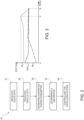
- Figure 3 shows, merely by way of example, the trend of the state of charge of the battery 12 as a result of the implementation of the method 50 in Figure 2 , in various use scenarios.
- the dWPT infrastructure 5 is present for the whole expected route of the vehicle 10, i.e. between a starting point A and an arrival point B.
- This information may be stored in the route data received at step S1.
- the state of charge of the battery at the starting point A is comprised within the desired neighbourhood (between the upper limit M 1 and the lower one M 2 ) of the optimal charge value S opt .
- the use profile determined in step S4 is such as to basically keep the state of charge of the battery 12 constant during the whole planned route of the vehicle 10.
- the recharging profile of the battery 12 may be chosen in such a way as to compensate for the charge consumed for the use, in particular for the propulsion, of the vehicle 10 during the planned route A-B.
- the dWPT infrastructure 5 is only present in a portion of the route planned by the vehicle 10, from the starting point A to an intermediate point C.
- This information about the distribution of recharging means may be stored in the route data received at step S1.
- the recharging profile determined at step S4 is adjusted in such a way that the battery 12 has, when the vehicle 10 is at the intermediate point C, a state of charge sufficient to enable the vehicle 10 to reach the destination point B.
- the state of charge of the battery 12 at the point C may be greater than the upper limit M 1 .
- the use profile of the battery 12 is chosen so that the state of charge of the battery 12 is comprised within the optimal charge range for as great a section as possible of the planned route A-B, while respecting at the same time the mission goal of the vehicle 10 during the planned route.
- the state of charge of the battery 12 at the starting point A is outside the optimal charge range (less than the lower limit M 2 ) and the dWPT infrastructure 5 is present along the whole planned route A-B.
- the recharging profile during the vehicle route is chosen so that the recharging power absorbed by the battery 12 is greater than the charge consumption of the battery 12.
- control unit 15 commands the propulsion system 11 so that the balance between power absorbed and power delivered is greater than zero (positive slope in the graph in Figure 3 ).
- control unit 15 controls the propulsion system 11 (power absorbed from the dWPT infrastructure 5 and/or power delivered by the battery 12) so that the state of charge of the battery 12 increases until the optimal charge range is reached.
- the recharging profile is amended so as to basically keep the state of charge constant until the arrival point B, similarly to what was discussed with reference to the first scenario in Figure 3 .
- Determining the use profile of the component of the vehicle 10 based on the status of the vehicle 10 and the planned route makes it possible to set a use profile of the component that takes into account the actual use of the vehicle 10.
- the use profile may enable optimising the cost of power associated with travelling the planned route by the vehicle 10.
- the use profile may be chosen so as to lengthen the service life of the component.
- the Applicant has actually verified that the maintenance of the state of charge of the battery 12 close to the optimal charge value, in particular in the neighbourhood of approximately 50%, for the whole planned route of the vehicle 10 or, in line with the mission goals and the presence of recharging facilities along the route, for as great a section of the planned route of the vehicle 10 as possible, makes it possible, surprisingly, to extend the service life of the battery 12.
- the possibility of maintaining the state of charge basically constant, i.e. obtaining a low depth of charge (DoD) of the battery 12 during the planned route contributes to further increasing the service life of the battery 12.
- DoD depth of charge
- the use of the dWPT infrastructure 5 makes it possible to obtain the desired recharging profile using a low recharging power for an extended time, in contrast to supplying high peaks of recharging power for reduced intervals of time.
- This provides the additional advantage of avoiding overloading the dWPT infrastructure 5 and, thus, of being able to use the dWPT infrastructure 5 to simultaneously recharge numerous vehicles.
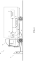
- Figure 4 shows a system 60 in which the vehicle 10 is recharged in a recharging station 61 when it is not running, before undertaking the planned route or in a recharging station at an intermediate position between the starting and arrival point.
- the starting point may correspond to the position of the recharging station 61 where the recharging operation occurs, and the arrival point may be a subsequent recharging station along the planned route or the final destination of the vehicle 10.
- the recharging station 61 is formed by a recharging column.
- the reception means of the propulsion system 11 comprise specific recharging connectors 62 that are configured to be physically coupled with the recharging station 61, for example specific cables 63, for recharging the battery 12.
- the recharging of the battery 12 may occur in a carpark or in other stopping or break stations configured for recharging the battery 12.
- the recharging station 61 may be of another kind, for example it may be a recharging station configured to be coupled with the propulsion system 11 of the vehicle 10 wirelessly, for example using WPT infrastructure arranged near a traffic light or other vehicle stopping points, along the planned route.
- the route data may also include a recharging time t ch that is available to recharge the battery 12.
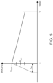
- the control unit 15 may determine the recharging profile of the battery 12 so that the state of charge (SOC) of the battery 12 at the end of the recharging event (for example at the time ti in which the vehicle 10 starts the planned route) has a starting value S start that is a function of the expected estimated charge consumption for the planned route of the vehicle 10 ( Figure 5 ).
- SOC state of charge
- the recharging profile during the recharging interval t ch and the discharge profile of the battery 12 during the vehicle 10 route have a trend, purely by way of example, that is linear; however, the recharging and/or discharging profile may have another trend.
- the starting value S start is determined so that the state of charge of the battery 12, during the planned route, is maintained around the optimal charge value S opt for as great a section as possible of the planned route, similarly to what was described with reference to the examples in Figure 3 .
- the starting value S start may, thus, be lower than the maximum state of charge (for example 100%) of the battery 12.
- the propulsion system 11 of the vehicle 10 may be configured to be coupled both to the WPT infrastructure 5 in Figure 1 and to the recharging station 61 in Figure 4 for recharging the battery 12.
Landscapes
- Engineering & Computer Science (AREA)
- Power Engineering (AREA)
- Transportation (AREA)
- Mechanical Engineering (AREA)
- Computer Networks & Wireless Communication (AREA)
- Life Sciences & Earth Sciences (AREA)
- Sustainable Development (AREA)
- Sustainable Energy (AREA)
- Electric Propulsion And Braking For Vehicles (AREA)
Abstract
A method implemented by a control unit (15) for controlling a functioning of a component (11, 12) of a vehicle (10). The method comprises the steps of: receiving (S1) route data indicative of a planned route of the vehicle; receiving (S2) vehicle data indicative of a status of the vehicle; determining (S3, S4) a use profile of the component of the vehicle based on the route data and the vehicle data; and controlling (S5) the functioning of the component of the vehicle based on the determined use profile.
Description
- This patent application claims priority from
Italian patent application no. 102023000010845 filed on May 29, 2023 - This invention relates to a method for controlling a functioning of a vehicle component.
- In particular, the preferred, but non-limiting, application of the invention is controlling the functioning of a propulsion system of an electric or hybrid vehicle comprising a battery.
- As known, the components of a vehicle, for example the components of a propulsion system of the vehicle (DC/DC converters, battery, etc.) or of an air conditioning system in the vehicle passenger compartment, impact the final cost of the vehicle.
- In addition, the components are subject to a drop in performance over time.
- Frequently replacing the vehicle components is disadvantageous both in economic and environmental terms.
- As a result, there is a need to provide a control method for the functining (or use profile) of a vehicle component that makes it possible to extend the service life of the component.
- With particular reference to electric or hybrid vehicles, they have a propulsion system comprising a battery.
- The propulsion system, especially the corresponding battery, is a vehicle component that is subject to ageing that causes significant decline in its performance over time.
- For example, the battery is subject to a reduction in the respective maximum capacity, i.e. the maximum power that can be stored in the battery, with a consequent negative impact on the autonomy of the vehicle.
- It is also known that the batteries have a significant impact on the cost of manufacturing the vehicle.
- Frequently changing the battery also has a significant negative impact on the environment.
- Despite this, the Applicant has observed that the known methods for controlling the use profile of the vehicle components, in particular a battery of a hybrid or electric vehicle, do not consider the actual use of the vehicle and do not ensure a long enough component service life.
- There is, thus, a need to provide a method for controlling the operation of a vehicle component, in particular a battery of a hybrid or electric vehicle, in order to extend its service life.
- The purpose of this invention is to meet the requirements mentioned above.
- The above-mentioned purpose is achieved with a method for controlling a functioning (or use profile) of a vehicle component, a system that implements the method, and a computer program, as claimed in the attached claims.
- In order to better understand this invention, preferred embodiments thereof will now be described by way of non-limiting example and with reference to the accompanying drawings, in which:
-
Figure 1 shows one embodiment of a system that implements the method according to this invention; -
Figure 2 shows a flow diagram of the method according to this invention; -
Figure 3 shows an example of a graph of the trend of the state of charge (SOC) of a battery of a vehicle inFigure 1 , in use, according to this invention; -
Figure 4 shows another embodiment of a system that implements the method according to this invention; and -
Figure 5 shows an example of a graph of the trend of the state of charge (SOC) of a battery of a vehicle inFigure 4 , in use, according to this invention. - The method proposed according to this invention involves controlling a functioning, indicated below also as operation mode or use profile, of a vehicle component, based on a planned route that the vehicle is travelling along or will travel along and based on the status of the vehicle.
- The vehicle is preferably an electric or hybrid propulsion vehicle.
- The vehicle component may be a vehicle propulsion system, in particular it may be a DC/DC converter, a battery, etc. of the vehicle propulsion system, or it may be an air conditioning system for the vehicle passenger compartment.
- For example, in the case of an electric or hybrid propulsion vehicle, the air conditioning system may comprise a heater such as a resistor or a heat pump supplied by the propulsion system of the vehicle.
- According to one preferred embodiment of the invention, the component is a propulsion system of an electric or hybrid vehicle, still more preferably a battery of the propulsion system.
- The use profile of the component may also be chosen as a function of a mission goal to be respected during the planned route.
- The mission goal may be indicated by a vehicle user. For example, the mission goal may comprise respecting a desired travel time; a maximum or minimum number of intermediate stops; one or more maximum and/or minimum speeds of the vehicle; or a desired travel cost, for example as a function of the cost of power used for recharging the vehicle battery.
- Below, the description will refer to controlling the use profile of the propulsion system of an electric or hybrid vehicle, in particular of the corresponding battery.
- By use profile of the propulsion system it is meant, hereinafter, unless otherwise specified, a specific mode of use of the propulsion system during vehicle traction (for example a maximum value of instantaneous and/or average power deliverable by the battery for the propulsion of the vehicle during the planned route) and/or a specific mode of use of the propulsion system during recharging of the battery (for example an instantaneous and/or average power value to be absorbed from a recharge source, a specific trend over time of the power absorbed, a maximum value of the state of charge of the battery obtained at the end of the recharge operation, etc.).
-
Figure 1 illustrates asystem 1 comprising a wireless power transfer infrastructure, hereinafter a WPT, 5 and avehicle 10 configured to be coupled with theWPT infrastructure 5. - The
vehicle 10 may be any mechanical means that is driven or can be driven by a human being (or even remotely driven), configured to transport people, animals, or goods, circulating on the road, tracks, or another surface. - The
vehicle 10 is an electric vehicle comprising anelectric propulsion system 11 in which electric supply is provided by one ormore batteries 12. - However, the
vehicle 10 may also be a hybrid propulsion vehicle, i.e. equipped with a propulsion system with two or more components, for example an electric motor and a thermal engine, which operate in synergy with other. - The
vehicle 10 includes a control unit 15 (for example an electronic control unit of thevehicle 10 or an additional processing unit other than the electronic control unit) and anacquisition system 16. - The
control unit 15 is provided with a microprocessor and a memory, which are operationally coupled. The memory may also be external to thecontrol unit 15, coupled to the microprocessor in a known way. - In this embodiment, the
control unit 15 also comprises aplanning module 18 configured to store the planned route that thevehicle 10 is travelling or will travel. - In any case, the
planning module 18 may be a remote unit, external to thevehicle 10, for example operating in the cloud, and configured to be coupled to thecontrol unit 15 via the internet network or another type of known connection. - The
acquisition system 16 comprises one or more sensors configured to acquire one or more physical quantities associated with the status of the vehicle and to provide vehicle data indicating the detected physical quantities to thecontrol unit 15. - For example, the vehicle data may indicate the weight of the
vehicle 10, travel speed and/or acceleration of thevehicle 10, or current geolocation (position) of thevehicle 10, etc. - In addition, the vehicle data may indicate the status of the
electric propulsion system 11, for example the state of charge (SOC) of thebattery 12, temperature of thebattery 12, etc. - In the embodiment in
Figure 1 , the WPTinfrastructure 5 is a dynamic infrastructure, also known as dWPT, configured to be coupled with thepropulsion system 11 of thevehicle 10 during driving of thevehicle 10. - In detail, the
dWPT infrastructure 5 comprises transfer means 20, for example one or more coils, arranged in proximity to the road surface, for example below the road surface, electrically coupled to apower supply network 21. - The transfer means 20 may be uniformly distributed along the planned route of the vehicle or may be distributed so as to form recharging islands spaced apart from each other, depending on the specific dWPT infrastructure.
- The
propulsion system 11 of thevehicle 10 comprises reception means 23, for example one or more coils, configured to be electrically coupled to the transfer means 20, for example via electromagnetic induction. - The reception means 23 are coupled to the
battery 12 of thevehicle 10 and provide recharging power to thebattery 12. - For example, the reception means 23 may also comprise specific voltage and/or current amplification, modulation, or rescaling circuits, etc., in order to modulate the recharging power absorbed by the
battery 12. - The
control unit 15 is operationally coupled to thepropulsion system 11 to control the functioning of thebattery 12 both during the traction of thevehicle 10, i.e. to control its delivered power, for example to control the maximum peaks of acceleration of thevehicle 10, and during recharging of thebattery 12, to control the power absorbed by thebattery 12. - Specifically, the
control unit 15 controls the coupling between the reception means 23 and the transfer means 20, so as to control the recharging profile of thebattery 12, i.e. the trend over time of the power absorbed by thebattery 12. - For example, the
control unit 15 may control activation or deactivation of the coupling between the reception means 23 and the transfer means 20, may adjust the coupling time thereof, the frequency of coupling events, the power absorbed during each coupling event, etc. - Hereinafter, with reference to
Figure 2 , amethod 50 for controlling the use profile of thepropulsion system 11 is described. - The
method 50 may be implemented locally by thecontrol unit 15 or in a distributed manner by thecontrol unit 15 and by a remote unit, not shown here, and operationally coupled to it. - For example, the remote unit may be a remote server in the cloud coupled to the
control unit 15 via a known connection and configured to perform operations having a high consumption of computational resources. - In a step S1, the
control unit 15 receives route data indicative of the expected or planned itinerary (route) that thevehicle 10 will travel until a final destination. - For example, the route data may be stored in the
planning module 18. - For example, the route data may be provided by a user and temporarily stored in the
planning module 18. - The route data comprise, for example, information relating to the current road conditions and to those expected during the planned route in instants of time subsequent to the current processing, such as, for example, expected road slopes, the presence of traffic, or distribution and position of stations for recharging of the
battery 12. - In addition, the route data may also comprise the cost of power at recharging stations along the planned route.
- In detail, with reference to the embodiment of
Figure 1 , the route data also include the position and distribution of the transfer means 20 of thedWPT infrastructure 5 along the planned route. - In practice, the transfer means 20 of the
dWPT infrastructure 5 form recharging stations of thebattery 12 along the planned route. - In other words, the route data comprise information about the itinerary of the
vehicle 10 that indicate the expected charge consumption of thebattery 12 and/or the possibility of recharging thebattery 12 along the planned route. - In a step S2, the
control unit 15 receives the vehicle data from theacquisition system 16. The vehicle data indicate the current status of thevehicle 10 and comprise, for example, thevehicle weight 10, state of charge of thebattery 12, temperature of thebattery 12, or current geolocation of thevehicle 10, etc. - Subsequently, the
processing unit 15 determines a use profile of thepropulsion system 11 based on the vehicle data and route data. - In detail, in this embodiment, the
control unit 15 estimates, step S3, an expected charge consumption of thebattery 12 based on the route data and vehicle data. - The estimate may be calculated through specific algorithms, for example previously trained artificial intelligence algorithms or via specific tables previously stored in the
control unit 15, in a known way. - Subsequently, step S4, the
control unit 15 determines the use profile of thepropulsion system 11 based on the expected charge consumption that was estimated at step S3. - The use profile is determined so that the state of charge of the
battery 12 is maintained around an optimal charge value Sopt. - In this embodiment, the determined use profile corresponds to the power to be absorbed from the
dWPT infrastructure 5, by thepropulsion system 11, for recharging thebattery 12. - In detail, the use profile may indicate the instantaneous power to be absorbed and/or the recharging profile of the
battery 12, i.e. the time behaviour of the power to be absorbed. - According to one embodiment, the determined use profile may also indicate the regulation of the power delivered by the
battery 12 for the propulsion of thevehicle 10. - For example, the optimal charge value Sopt may be comprised between 40% and 60%, in particular approximately equal to 50%, of the maximum charge capacity of the
battery 12. - The determined use profile may be such that the neighbourhood of the optimal state of charge is a range smaller, in particular strictly smaller, than the range comprised between the maximum state of charge (for example 100%) and the minimum state of charge (for example 0%) of the
battery 12. - For example, the neighbourhood of the optimal charge value Sopt may correspond to a range of the state of charge of the
battery 12 from 10% to 90%, in particular so that the state of charge is maintained within a deviation of 20%, in particular of 10%, with respect to the optimal charge value Sopt. - The
control unit 15 controls, step S5, thepropulsion system 11 based on the use profile determined in step S4. - For example, the
control unit 15 may provide a control signal to thepropulsion system 11 that is configured to control thepropulsion system 11, for example the reception means 23 and/or thebattery 12. - In other words, the
control unit 15 configures thepropulsion system 11 and adjusts its functioning so as to operate based on the determined use profile. - In practice, the
control unit 15 may for example control number, duration, and/or frequency of the coupling events between the reception means 23 of thevehicle 10 and the transfer means 20 of thedWPT infrastructure 5. - The
control unit 15 may control, for example, the instantaneous power absorbed by thebattery 12 in each coupling event between the reception means 23 of thevehicle 10 and the transfer means 20 of thedWPT infrastructure 5. - In addition, or alternatively, if the use profile also comprises information relating to the functioning of the
propulsion system 11 during traction, thecontrol unit 15 can also regulate the power that can be delivered by thebattery 12 for the propulsion of thevehicle 10. -
Figure 3 shows, merely by way of example, the trend of the state of charge of thebattery 12 as a result of the implementation of themethod 50 inFigure 2 , in various use scenarios. - In a first example scenario, identified with a solid line in
Figure 3 , thedWPT infrastructure 5 is present for the whole expected route of thevehicle 10, i.e. between a starting point A and an arrival point B. - This information may be stored in the route data received at step S1.
- In the example considered, the state of charge of the battery at the starting point A is comprised within the desired neighbourhood (between the upper limit M1 and the lower one M2) of the optimal charge value Sopt.
- The use profile determined in step S4 is such as to basically keep the state of charge of the
battery 12 constant during the whole planned route of thevehicle 10. - In practice, the recharging profile of the
battery 12 may be chosen in such a way as to compensate for the charge consumed for the use, in particular for the propulsion, of thevehicle 10 during the planned route A-B. - In a second example scenario, the
dWPT infrastructure 5 is only present in a portion of the route planned by thevehicle 10, from the starting point A to an intermediate point C. - In practice, between the intermediate point C and the arrival point B, there are no further recharging stations.
- This information about the distribution of recharging means may be stored in the route data received at step S1.
- The trend of the state of charge of the
battery 12 in the second scenario is indicated by a dashed line inFigure 3 . - In this case, the recharging profile determined at step S4 is adjusted in such a way that the
battery 12 has, when thevehicle 10 is at the intermediate point C, a state of charge sufficient to enable thevehicle 10 to reach the destination point B. - In this embodiment, the state of charge of the
battery 12 at the point C may be greater than the upper limit M1. - However, the use profile of the
battery 12 is chosen so that the state of charge of thebattery 12 is comprised within the optimal charge range for as great a section as possible of the planned route A-B, while respecting at the same time the mission goal of thevehicle 10 during the planned route. - In a third example scenario, the state of charge of the
battery 12 at the starting point A is outside the optimal charge range (less than the lower limit M2) and thedWPT infrastructure 5 is present along the whole planned route A-B. - The trend of the state of charge of the
battery 12 in the third scenario is indicated by a dash-point line inFigure 3 . - In this scenario, the recharging profile during the vehicle route is chosen so that the recharging power absorbed by the
battery 12 is greater than the charge consumption of thebattery 12. - In other words, the
control unit 15 commands thepropulsion system 11 so that the balance between power absorbed and power delivered is greater than zero (positive slope in the graph inFigure 3 ). - In practice, the
control unit 15 controls the propulsion system 11 (power absorbed from thedWPT infrastructure 5 and/or power delivered by the battery 12) so that the state of charge of thebattery 12 increases until the optimal charge range is reached. - In response to reaching the optimal charging range, the recharging profile is amended so as to basically keep the state of charge constant until the arrival point B, similarly to what was discussed with reference to the first scenario in
Figure 3 . - This method makes it possible to achieve numerous advantages.
- Determining the use profile of the component of the
vehicle 10 based on the status of thevehicle 10 and the planned route makes it possible to set a use profile of the component that takes into account the actual use of thevehicle 10. - In this way, it is possible to respect the desired mission goals during the planned route.
- For example, the use profile may enable optimising the cost of power associated with travelling the planned route by the
vehicle 10. - In particular, the use profile may be chosen so as to lengthen the service life of the component.
- With reference to the embodiment discussed above, the Applicant has actually verified that the maintenance of the state of charge of the
battery 12 close to the optimal charge value, in particular in the neighbourhood of approximately 50%, for the whole planned route of thevehicle 10 or, in line with the mission goals and the presence of recharging facilities along the route, for as great a section of the planned route of thevehicle 10 as possible, makes it possible, surprisingly, to extend the service life of thebattery 12. - In addition, the possibility of maintaining the state of charge basically constant, i.e. obtaining a low depth of charge (DoD) of the
battery 12 during the planned route contributes to further increasing the service life of thebattery 12. - The use of the
dWPT infrastructure 5 makes it possible to obtain the desired recharging profile using a low recharging power for an extended time, in contrast to supplying high peaks of recharging power for reduced intervals of time. - This provides the additional advantage of avoiding overloading the
dWPT infrastructure 5 and, thus, of being able to use thedWPT infrastructure 5 to simultaneously recharge numerous vehicles. -
Figure 4 shows asystem 60 in which thevehicle 10 is recharged in a rechargingstation 61 when it is not running, before undertaking the planned route or in a recharging station at an intermediate position between the starting and arrival point. - For example, the starting point may correspond to the position of the recharging
station 61 where the recharging operation occurs, and the arrival point may be a subsequent recharging station along the planned route or the final destination of thevehicle 10. - In the embodiment in
Figure 4 , the rechargingstation 61 is formed by a recharging column. - The reception means of the
propulsion system 11 comprisespecific recharging connectors 62 that are configured to be physically coupled with the rechargingstation 61, for examplespecific cables 63, for recharging thebattery 12. - For example, the recharging of the
battery 12 may occur in a carpark or in other stopping or break stations configured for recharging thebattery 12. - However, the recharging
station 61 may be of another kind, for example it may be a recharging station configured to be coupled with thepropulsion system 11 of thevehicle 10 wirelessly, for example using WPT infrastructure arranged near a traffic light or other vehicle stopping points, along the planned route. - In this embodiment, the route data may also include a recharging time tch that is available to recharge the
battery 12. - The
control unit 15 may determine the recharging profile of thebattery 12 so that the state of charge (SOC) of thebattery 12 at the end of the recharging event (for example at the time ti in which thevehicle 10 starts the planned route) has a starting value Sstart that is a function of the expected estimated charge consumption for the planned route of the vehicle 10 (Figure 5 ). - In
Figure 5 , the recharging profile during the recharging interval tch and the discharge profile of thebattery 12 during thevehicle 10 route (between the points in time ti and tf) have a trend, purely by way of example, that is linear; however, the recharging and/or discharging profile may have another trend. - In detail, the starting value Sstart is determined so that the state of charge of the
battery 12, during the planned route, is maintained around the optimal charge value Sopt for as great a section as possible of the planned route, similarly to what was described with reference to the examples inFigure 3 . - The starting value Sstart may, thus, be lower than the maximum state of charge (for example 100%) of the
battery 12. - This is in contrast with the known recharging methods for electric vehicle batteries, in which in each recharging event the goal of each recharging event is to reach the maximum state of charge, irrespective of the planned route of the
vehicle 10. - Similarly to what was discussed with reference to
Figures 1-3 , the Applicant verified that the possibility of modulating the recharging profile of thebattery 12 during the interval tch based on the planned route makes it possible to extend the service life of thebattery 12. - Finally, it is clear that changes may be made to the system and method, and variations produced thereto, according to this invention that, in any case, do not depart from the scope of protection defined by the claims.
- For example, the embodiments shown and described may be combined with each other to provide additional solutions.
- For example, the
propulsion system 11 of thevehicle 10 may be configured to be coupled both to theWPT infrastructure 5 inFigure 1 and to the rechargingstation 61 inFigure 4 for recharging thebattery 12.
Claims (16)
- A method implemented by a control unit (15) for controlling a functioning of a component (11, 12) of a vehicle (10), comprising:- receiving (S1) route data indicative of a planned route of the vehicle;- receiving (S2) vehicle data indicative of a status of the vehicle;- determining (S3, S4) a use profile of the component of the vehicle based on the route data and the vehicle data; and- controlling (S5) the functioning of the component of the vehicle based on the determined profile use.
- The method according to the preceding claim, wherein the vehicle (10) is an electric or a hybrid vehicle having a propulsion system (11) comprising a battery (12), wherein determining a profile use comprises:estimating (S3) a charge consumption of the battery during the planned route, based on the route data and the vehicle data; anddetermining (S4) the use profile of the propulsion system based on the estimated charge consumption.
- The method according to the preceding claim, wherein the use profile of the propulsion system (11) is determined so that the state of charge of the battery (12) remains, during the planned route, in the neighbourhood (M1-M2) of an optimal charge value (Sopt), for example equal to about 50%.
- The method according to claim 2 o 3, wherein determining a use profile comprises determining a mode of use of the propulsion system (11) during a recharge operation of the battery (12).
- The method according to the preceding claim, wherein determining a mode of use of the propulsion system (11) during a recharge operation of the battery comprises determining one or more of: an instantaneous and/or average power value to be absorbed by the battery (12); a time behaviour of the power to be absorbed by the battery; and a final state of charge of the battery in response to a recharge operation.
- The method according to any one of claims 2-5, wherein determining a use profile comprises determining a mode of use of the propulsion system (11) during the traction of the vehicle.
- The method according to the preceding claim, wherein determining a mode of use of the propulsion system (11) during the traction of the vehicle comprises determining a maximum value of instantaneous and/or average power that is deliverable, by the battery, during the planned route.
- The method according to any one of the preceding claims, wherein the route data are indicative of road conditions of the planned route and comprise one or more of: road slopes, traffic, distribution and location of stations for recharging a battery (12) of the vehicle along the planned route.
- The method according to any one of the preceding claims, wherein the vehicle data are data acquired by an acquisition system (16) of the vehicle and are indicative of one or more parameters chosen from: vehicle weight, vehicle geolocation, state of charge of a vehicle battery (12), battery temperature.
- The method according to any one of claims 2-9, wherein the vehicle is configured to be coupled to a wireless power transfer, WPT, infrastructure (5) for recharging of the battery while the vehicle is in motion,wherein determining a use profile of the propulsion system comprises determining a power to be absorbed, by the battery, from the WPT infrastructure, andwherein controlling the functioning of the propulsion system comprises controlling the coupling between the propulsion system and the wireless power transfer infrastructure so that the battery (12) absorbs the determined power to the absorbed.
- The method according to any of claims 2-10, wherein the vehicle is configured to be coupled, when the vehicle is stationary, to a recharging station (61) for recharging the battery (12),
wherein determining a use profile of the propulsion system comprises determining a recharging profile of the battery and/or a charge level (Sstart) of the battery to be reached at the end of a recharge operation, based on the route data and the vehicle data. - A system (1; 60) comprising:a control unit (15); anda vehicle (10) comprising an acquisition system (16) configured to provide vehicle data indicative of a status of the vehicle,the control unit being configured to:- receive (S1) route data indicative of a planned route of the vehicle;- receive (S2) vehicle data indicative of the status of the vehicle;- determine (S3, S4) a use profile of a component (11, 12) of the vehicle based on the route data and the vehicle data; and- controlling (S5) the functioning of the component of the vehicle based on the determined profile use.
- The system according to the preceding claim, wherein the vehicle is an electric or a hybrid vehicle having a propulsion system (11) comprising a battery (12),wherein the control unit is configured to estimate (S3) a charge consumption of the battery during the planned route, based on the route data and the vehicle data, andwherein the control unit is configured to determine the use profile of the propulsion system (11) of the vehicle based on the route data and the vehicle data.
- The system according to the preceding claim, further comprising a recharging station (5; 61), the propulsion system of the vehicle being configured to couple to the recharging station for recharging the battery (12),wherein the use profile of the propulsion system (11) comprises a recharging profile of the battery, andwherein the control unit is configured to control the coupling of the propulsion system with the recharging station based on the determined recharging profile.
- The system (1) according to the preceding claim, wherein the recharging station is formed by means for wireless power transfer (23, 5).
- A computer program comprising instructions that, when executed by a control unit (15) couplable to a vehicle (10), cause the control unit to perform the method according to any of claims 1-11.
Applications Claiming Priority (1)
| Application Number | Priority Date | Filing Date | Title |
|---|---|---|---|
| IT102023000010845A IT202300010845A1 (en) | 2023-05-29 | 2023-05-29 | METHOD FOR CHECKING THE OPERATION OF A VEHICLE COMPONENT |
Publications (1)
| Publication Number | Publication Date |
|---|---|
| EP4470821A1 true EP4470821A1 (en) | 2024-12-04 |
Family
ID=88097974
Family Applications (1)
| Application Number | Title | Priority Date | Filing Date |
|---|---|---|---|
| EP24178161.6A Pending EP4470821A1 (en) | 2023-05-29 | 2024-05-27 | Method for controlling a functioning of a component of a vehicle |
Country Status (2)
| Country | Link |
|---|---|
| EP (1) | EP4470821A1 (en) |
| IT (1) | IT202300010845A1 (en) |
Citations (5)
| Publication number | Priority date | Publication date | Assignee | Title |
|---|---|---|---|---|
| JP2017204947A (en) * | 2016-05-12 | 2017-11-16 | 株式会社ダイヘン | Automated guided vehicle system |
| JP2019041455A (en) * | 2017-08-23 | 2019-03-14 | 本田技研工業株式会社 | Electric vehicle |
| JP2023015574A (en) * | 2021-07-20 | 2023-02-01 | トヨタ自動車株式会社 | Charging quantity calculation device and charging system |
| US20230032752A1 (en) * | 2021-07-30 | 2023-02-02 | Toyota Jidosha Kabushiki Kaisha | Running mode proposal device, navigation device, and running control device |
| WO2023078590A1 (en) * | 2021-11-05 | 2023-05-11 | Volvo Truck Corporation | Joint optimization of routes and driving parameters for cycle degradation minimization in electric vehicles |
-
2023
- 2023-05-29 IT IT102023000010845A patent/IT202300010845A1/en unknown
-
2024
- 2024-05-27 EP EP24178161.6A patent/EP4470821A1/en active Pending
Patent Citations (5)
| Publication number | Priority date | Publication date | Assignee | Title |
|---|---|---|---|---|
| JP2017204947A (en) * | 2016-05-12 | 2017-11-16 | 株式会社ダイヘン | Automated guided vehicle system |
| JP2019041455A (en) * | 2017-08-23 | 2019-03-14 | 本田技研工業株式会社 | Electric vehicle |
| JP2023015574A (en) * | 2021-07-20 | 2023-02-01 | トヨタ自動車株式会社 | Charging quantity calculation device and charging system |
| US20230032752A1 (en) * | 2021-07-30 | 2023-02-02 | Toyota Jidosha Kabushiki Kaisha | Running mode proposal device, navigation device, and running control device |
| WO2023078590A1 (en) * | 2021-11-05 | 2023-05-11 | Volvo Truck Corporation | Joint optimization of routes and driving parameters for cycle degradation minimization in electric vehicles |
Also Published As
| Publication number | Publication date |
|---|---|
| IT202300010845A1 (en) | 2024-11-29 |
Similar Documents
| Publication | Publication Date | Title |
|---|---|---|
| US10464547B2 (en) | Vehicle with model-based route energy prediction, correction, and optimization | |
| US11964575B2 (en) | Control apparatus | |
| US10759303B2 (en) | Autonomous vehicle route planning | |
| EP2307226B1 (en) | Method and system for extending life of a vehicle energy storage device | |
| KR101432417B1 (en) | Battery charging system | |
| US7890228B2 (en) | Power source monitoring system for AGVs and method | |
| US20190084435A1 (en) | Electric vehicle charging by adjusting charger current | |
| US12011968B2 (en) | Interface system for connecting a vehicle and a transport climate control system | |
| KR102148376B1 (en) | Energy management system for a non-railbound vehicle | |
| EP2648953B1 (en) | Method for controlling a hybrid automotive vehicle and hybrid vehicle adapted to such a method | |
| CN110506359B (en) | Method for thermally regulating a fast-charging battery system of an electric motor vehicle | |
| US20180281606A1 (en) | Method For Coordinating Charging Processes Of Electric Vehicles As Well As Electrically Operated Motor Vehicle And Supply Vehicle | |
| US9321366B1 (en) | Electric vehicle charging by adjusting charger current | |
| US11872903B2 (en) | System and method for recalibrating a traction battery through bi-directional power transfer | |
| JP2023020483A (en) | Travel mode proposal device, navigation device, and travel control device | |
| CN112441027A (en) | Vehicle and method for operating a vehicle | |
| US11603010B2 (en) | Predicting charging time for battery of electrified vehicle | |
| EP3672017B1 (en) | System and method for modulating a charging rate for charging a battery of a vehicle as a function of an expected passenger load | |
| EP3540903A1 (en) | Methods and systems for managing bi-directional converter based battery modules | |
| CN110979031A (en) | Intelligent energy management method for double-source trackless vehicle | |
| US20210129687A1 (en) | System and process for utilizing a deployable flex range battery to augment a primary battery | |
| EP4551422B1 (en) | A method of controlling an electric power system of a fuel cell electric vehicle | |
| US12030394B2 (en) | Contactless power feeding system, power feeding device, and power feeding management server | |
| JP4709654B2 (en) | Transportation system | |
| US20230278465A1 (en) | Battery temperature adjustment system |
Legal Events
| Date | Code | Title | Description |
|---|---|---|---|
| PUAI | Public reference made under article 153(3) epc to a published international application that has entered the european phase |
Free format text: ORIGINAL CODE: 0009012 |
|
| STAA | Information on the status of an ep patent application or granted ep patent |
Free format text: STATUS: THE APPLICATION HAS BEEN PUBLISHED |
|
| AK | Designated contracting states |
Kind code of ref document: A1 Designated state(s): AL AT BE BG CH CY CZ DE DK EE ES FI FR GB GR HR HU IE IS IT LI LT LU LV MC ME MK MT NL NO PL PT RO RS SE SI SK SM TR |
|
| STAA | Information on the status of an ep patent application or granted ep patent |
Free format text: STATUS: REQUEST FOR EXAMINATION WAS MADE |
|
| 17P | Request for examination filed |
Effective date: 20250603 |