EP4470819A1 - Four-wheel independent steering control apparatus and method - Google Patents
Four-wheel independent steering control apparatus and method Download PDFInfo
- Publication number
- EP4470819A1 EP4470819A1 EP23176084.4A EP23176084A EP4470819A1 EP 4470819 A1 EP4470819 A1 EP 4470819A1 EP 23176084 A EP23176084 A EP 23176084A EP 4470819 A1 EP4470819 A1 EP 4470819A1
- Authority
- EP
- European Patent Office
- Prior art keywords
- wheel
- vehicle
- topology
- torques
- movement
- Prior art date
- Legal status (The legal status is an assumption and is not a legal conclusion. Google has not performed a legal analysis and makes no representation as to the accuracy of the status listed.)
- Pending
Links
Images


Classifications
-
- B—PERFORMING OPERATIONS; TRANSPORTING
- B60—VEHICLES IN GENERAL
- B60L—PROPULSION OF ELECTRICALLY-PROPELLED VEHICLES; SUPPLYING ELECTRIC POWER FOR AUXILIARY EQUIPMENT OF ELECTRICALLY-PROPELLED VEHICLES; ELECTRODYNAMIC BRAKE SYSTEMS FOR VEHICLES IN GENERAL; MAGNETIC SUSPENSION OR LEVITATION FOR VEHICLES; MONITORING OPERATING VARIABLES OF ELECTRICALLY-PROPELLED VEHICLES; ELECTRIC SAFETY DEVICES FOR ELECTRICALLY-PROPELLED VEHICLES
- B60L15/00—Methods, circuits, or devices for controlling the traction-motor speed of electrically-propelled vehicles
- B60L15/20—Methods, circuits, or devices for controlling the traction-motor speed of electrically-propelled vehicles for control of the vehicle or its driving motor to achieve a desired performance, e.g. speed, torque, programmed variation of speed
-
- B—PERFORMING OPERATIONS; TRANSPORTING
- B62—LAND VEHICLES FOR TRAVELLING OTHERWISE THAN ON RAILS
- B62D—MOTOR VEHICLES; TRAILERS
- B62D6/00—Arrangements for automatically controlling steering depending on driving conditions sensed and responded to, e.g. control circuits
- B62D6/002—Arrangements for automatically controlling steering depending on driving conditions sensed and responded to, e.g. control circuits computing target steering angles for front or rear wheels
-
- B—PERFORMING OPERATIONS; TRANSPORTING
- B62—LAND VEHICLES FOR TRAVELLING OTHERWISE THAN ON RAILS
- B62D—MOTOR VEHICLES; TRAILERS
- B62D5/00—Power-assisted or power-driven steering
- B62D5/04—Power-assisted or power-driven steering electrical, e.g. using an electric servo-motor connected to, or forming part of, the steering gear
- B62D5/0418—Electric motor acting on road wheel carriers
-
- B—PERFORMING OPERATIONS; TRANSPORTING
- B62—LAND VEHICLES FOR TRAVELLING OTHERWISE THAN ON RAILS
- B62D—MOTOR VEHICLES; TRAILERS
- B62D5/00—Power-assisted or power-driven steering
- B62D5/04—Power-assisted or power-driven steering electrical, e.g. using an electric servo-motor connected to, or forming part of, the steering gear
- B62D5/0457—Power-assisted or power-driven steering electrical, e.g. using an electric servo-motor connected to, or forming part of, the steering gear characterised by control features of the drive means as such
-
- B—PERFORMING OPERATIONS; TRANSPORTING
- B62—LAND VEHICLES FOR TRAVELLING OTHERWISE THAN ON RAILS
- B62D—MOTOR VEHICLES; TRAILERS
- B62D7/00—Steering linkage; Stub axles or their mountings
- B62D7/06—Steering linkage; Stub axles or their mountings for individually-pivoted wheels, e.g. on king-pins
- B62D7/14—Steering linkage; Stub axles or their mountings for individually-pivoted wheels, e.g. on king-pins the pivotal axes being situated in more than one plane transverse to the longitudinal centre line of the vehicle, e.g. all-wheel steering
-
- B—PERFORMING OPERATIONS; TRANSPORTING
- B62—LAND VEHICLES FOR TRAVELLING OTHERWISE THAN ON RAILS
- B62D—MOTOR VEHICLES; TRAILERS
- B62D7/00—Steering linkage; Stub axles or their mountings
- B62D7/06—Steering linkage; Stub axles or their mountings for individually-pivoted wheels, e.g. on king-pins
- B62D7/14—Steering linkage; Stub axles or their mountings for individually-pivoted wheels, e.g. on king-pins the pivotal axes being situated in more than one plane transverse to the longitudinal centre line of the vehicle, e.g. all-wheel steering
- B62D7/15—Steering linkage; Stub axles or their mountings for individually-pivoted wheels, e.g. on king-pins the pivotal axes being situated in more than one plane transverse to the longitudinal centre line of the vehicle, e.g. all-wheel steering characterised by means varying the ratio between the steering angles of the steered wheels
- B62D7/1509—Steering linkage; Stub axles or their mountings for individually-pivoted wheels, e.g. on king-pins the pivotal axes being situated in more than one plane transverse to the longitudinal centre line of the vehicle, e.g. all-wheel steering characterised by means varying the ratio between the steering angles of the steered wheels with different steering modes, e.g. crab-steering, or steering specially adapted for reversing of the vehicle
Definitions
- Exemplary embodiments of the present disclosure relate to a four-wheel independent steering control apparatus and method.
- the pitch motion thereof in the air may be affected.
- yaw and roll motions are unaffected, since the yaw and roll motions may not be affected unless the steering configuration of the wheel is changed.
- Various embodiments are directed to a four-wheel independent steering control apparatus and method allowing wheel torques and steering geometries of a vehicle to be adjusted in mid-air.
- a four-wheel independent steering control apparatus may include: wheel steering modules configured to independently steer respective wheels of a vehicle; and a processor configured to detect a mid-air state on the basis of measured information of the vehicle and adjust propulsion torques and steering geometries of the wheels according to the mid-air state by means of the wheel steering modules.
- the measured information may include at least one from among acceleration, speed of rotation, wheel angles, torques, a distance of the vehicle from the ground.
- the processor may set a front right wheel and a rear left wheel to be a first wheel pair, set a front left wheel and a rear right wheel to be a second wheel pair, instruct a symmetric movement of the first wheel pair and the second wheel pair, and divide a steering motion of the first wheel pair and the second wheel pair into a first sub-movement in which the first wheel pair and the second wheel pair move in opposite directions and a second sub-movement in which the first wheel pair and the second wheel pair move in the same direction.
- the processor may include: a calculator configured to determine at least one mid-air state of a free-fall state and a hovering state on the basis of at least one of acceleration and a distance of the vehicle from the ground included in the measured information, set wheel positions according to the wheel topology corresponding to the determined mid-air state, and calculate the relationship between the wheels and vehicle's body torques on the basis of the set wheel positions; a controller configured to calculate torques applied across vehicle's body on the basis of a difference between a desired states vector and an output states vector of a vehicle's body plant mode; and an application part configured to calculate wheel torques by applying the calculated torques applied across vehicle's body to the relationship between the wheels and the vehicle's body torques, calculate the calculated wheel torques and torques included in the measured information, and apply the calculated torques to the vehicle's body plant model.
- a calculator configured to determine at least one mid-air state of a free-fall state and a hovering state on the basis of at least one of acceleration and a distance of the vehicle from the ground
- the wheel topology may include at least one of first wheel topology in which a first sub-movement is 0° and a second sub-movement is 0°, second wheel topology in which the first sub-movement is 45° and the second sub-movement is 0°, third wheel topology in which the first sub-movement is 0° and the second sub-movement is 45°, and fourth wheel topology in which the first sub-movement is 45° and the second sub-movement is 45°.
- the first topology may be configured to control a pitch motion without affecting directions of yaw and roll, wherein the front right wheel and the rear left wheel are 0°, while the front left wheel and the rear right wheel RR are 0°.
- the second wheel topology may equalize authority over the pitch and roll (y' axis and x' axis) by adjusting the first sub-movement and control the yaw motion by adjusting the second sub-movement, wherein the front right wheel and the rear left wheel are 45°, while the front left wheel and the rear right wheel are -45°.
- the third topology may change orthogonal control authority over the pitch (y axis) and control the yaw motion (z axis) of a vehicle base by adjusting the second sub-movement, wherein the front right wheel and the rear left wheel are -45°, while the front left wheel and the rear right wheel are -45°.
- the calculator may determine the mid-air state to be the free-fall state and the wheel topology to be second wheel topology.
- the calculator may determine the mid-air state to be the hovering state and the wheel topology to be fourth wheel topology.
- the application part may inverse the relationship between the wheels and the vehicle's body torques and apply torques applied across a vehicle's body to the inversed relationship.
- a four-wheel independent steering control method may include: detecting, by a processor, a mid-air state on the basis of measured information of a vehicle; setting, by the processor, wheel positions according to the mid-air state; calculating, by the processor, a relationship between wheels and vehicle's body torques on the basis of the set wheel positions and inversing the calculated relationship; and calculating wheel torques by applying torques applied across a vehicle's body to the inversed relationship.
- the processor may determine the wheel topology to be second wheel topology and sets the wheel positions according to the second wheel topology, and when the mid-air state is a hovering state, the processor may determine the wheel topology to be fourth wheel topology and sets the wheel positions according to the fourth wheel topology.
- the four-wheel independent steering control apparatus and method may adjust the direction of the vehicle (the directions of the wheels) in mid-air by adjusting the wheel torques and the steering geometries in mid-air. Touchdown parallel to the ground and load distribution proportional to four wheels may be ensured. The risk of landing upside down in the touchdown may be minimized. The reliability of the vehicle may be improved, and thus steering correction efforts required to the driver may be minimized.
- the components described in the example embodiments may be implemented by hardware components including, for example, at least one digital signal processor (DSP), a processor, a controller, an application-specific integrated circuit (ASIC), a programmable logic element, such as an FPGA, other electronic devices, or combinations thereof.
- DSP digital signal processor
- ASIC application-specific integrated circuit
- FPGA field-programmable gate array
- At least some of the functions or the processes described in the example embodiments may be implemented by software, and the software may be recorded on a recording medium.
- the components, the functions, and the processes described in the example embodiments may be implemented by a combination of hardware and software.
- the method according to example embodiments may be embodied as a program that is executable by a computer, and may be implemented as various recording media such as a magnetic storage medium, an optical reading medium, and a digital storage medium.
- Various techniques described herein may be implemented as digital electronic circuitry, or as computer hardware, firmware, software, or combinations thereof.
- the techniques may be implemented as a computer program product, i.e., a computer program tangibly embodied in an information carrier, e.g., in a machine-readable storage device (for example, a computer-readable medium) or in a propagated signal for processing by, or to control an operation of a data processing apparatus, e.g., a programmable processor, a computer, or multiple computers.
- a computer program(s) may be written in any form of a programming language, including compiled or interpreted languages and may be deployed in any form including a stand-alone program or a module, a component, a subroutine, or other units suitable for use in a computing environment.
- a computer program may be deployed to be executed on one computer or on multiple computers at one site or distributed across multiple sites and interconnected by a communication network.
- processors suitable for execution of a computer program include, by way of example, both general and special purpose microprocessors, and any one or more processors of any kind of digital computer.
- a processor will receive instructions and data from a read-only memory or a random access memory or both.
- Elements of a computer may include at least one processor to execute instructions and one or more memory devices to store instructions and data.
- a computer will also include or be coupled to receive data from, transfer data to, or perform both on one or more mass storage devices to store data, e.g., magnetic, magneto-optical disks, or optical disks.
- Examples of information carriers suitable for embodying computer program instructions and data include semiconductor memory devices, for example, magnetic media such as a hard disk, a floppy disk, and a magnetic tape, optical media such as a compact disk read only memory (CD-ROM), a digital video disk (DVD), etc. and magneto-optical media such as a floptical disk, and a read only memory (ROM), a random access memory (RAM), a flash memory, an erasable programmable ROM (EPROM), and an electrically erasable programmable ROM (EEPROM) and any other known computer readable medium.
- a processor and a memory may be supplemented by, or integrated into, a special purpose logic circuit.
- the processor may run an operating system (OS) and one or more software applications that run on the OS.
- the processor device also may access, store, manipulate, process, and create data in response to execution of the software.
- OS operating system
- the description of a processor device is used as singular; however, one skilled in the art will be appreciated that a processor device may include multiple processing elements and/or multiple types of processing elements.
- a processor device may include multiple processors or a processor and a controller.
- different processing configurations are possible, such as parallel processors.
- non-transitory computer-readable media may be any available media that may be accessed by a computer, and may include both computer storage media and transmission media.
- components that are distinguished from each other are intended to clearly illustrate each feature. However, it does not necessarily mean that the components are separate. That is, a plurality of components may be integrated into one hardware or software unit, or a single component may be distributed into a plurality of hardware or software units. Thus, unless otherwise noted, such integrated or distributed embodiments are also included within the scope of the present disclosure.
- components described in the various embodiments are not necessarily essential components, and some may be optional components. Accordingly, embodiments consisting of a subset of the components described in one embodiment are also included within the scope of the present disclosure. In addition, embodiments that include other components in addition to the components described in the various embodiments are also included in the scope of the present disclosure.
- a component when referred to as being "linked,” “coupled,” or “connected” to another component, it is understood that not only a direct connection relationship but also an indirect connection relationship through an intermediate component may also be included.
- a component when referred to as “comprising” or “having” another component, it may mean further inclusion of another component not the exclusion thereof, unless explicitly described to the contrary.
- first, second, etc. are used only for the purpose of distinguishing one component from another, and do not limit the order or importance of components, etc., unless specifically stated otherwise.
- a first component in one exemplary embodiment may be referred to as a second component in another embodiment, and similarly a second component in one exemplary embodiment may be referred to as a first component.
- components that are distinguished from each other are intended to clearly illustrate each feature. However, it does not necessarily mean that the components are separate. That is, a plurality of components may be integrated into one hardware or software unit, or a single component may be distributed into a plurality of hardware or software units. Thus, unless otherwise noted, such integrated or distributed embodiments are also included within the scope of the present disclosure.
- components described in the various embodiments are not necessarily essential components, and some may be optional components. Accordingly, embodiments consisting of a subset of the components described in one embodiment are also included within the scope of the present disclosure. In addition, exemplary embodiments that include other components in addition to the components described in the various embodiments are also included in the scope of the present disclosure.
- implementations described in the present specification may be made by, for example, a method or a process, a device, a software program, a data stream, or a signal.
- the implementations are discussed only in the context of a single form (for example, discussed by the method only), the discussed features may also be implemented by another form (for example, a device or a program).
- the device may be implemented by suitable hardware, software, and firmware.
- the method may be implemented, for example, in a computer, a microprocessor, an integrated circuit, or a device such as a processor that generally refers to a processing device including a programmable logic device.
- the processor includes a computer, a cellular phone, and a communication device such as a portable/personal digital assistant (PDA) or another device.
- PDA portable/personal digital assistant
- a vehicle described in the present specification may include a four-wheeled independent drive and steering (4WIDS) vehicle.
- 4WIDS four-wheeled independent drive and steering
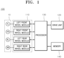
- FIG. 1 is a diagram illustrating a four-wheel independent steering control apparatus according to an embodiment of the present disclosure
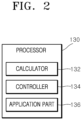
- FIG. 2 is a diagram illustrating the configuration of the processor illustrated in FIG. 1
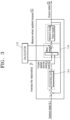
- FIG. 3 is a diagram illustrating the controller and the application part illustrated in FIG. 2
- FIGS. 4A to 4D are example diagrams illustrating wheel topology according to an embodiment of the present disclosure.
- a four-wheel independent steering control apparatus 100 includes wheel steering modules 110, a drive unit 120, a processor 130, and a memory 140.
- the memory 140 is a component configured to store data related to operations of the four-wheel independent steering control apparatus 100.
- an application program (or an applet) configured to detect a mid-air state on the basis of measured information of a vehicle and adjust propulsion torque and steering geometry of respective wheels 10 according to the mid-air state, or the like, may be stored in the memory 140.
- the information stored may be selected by the processor 130 as required. That is, various types of data generated during execution of an operating system or an application program (or an applet) for driving the four-wheel independent steering control apparatus 100 are stored in the memory 140.
- the memory 140 collectively refers to a non-volatile storage device that retains stored information even when power is not supplied and a volatile storage device that requires power to retain stored information.
- the wheel steering modules 110 are provided for the wheels 10, respectively, thereby allowing the wheels 10 to be steered independently.
- the wheel steering modules 110 include a left front wheel module to steer the front left wheel FL, a right front wheel module to steer the front right wheel FR, a left rear wheel module to steer the rear left wheel RL, and a right rear wheel module to steer the rear right wheel RR.
- Each of the wheel steering modules 110 may include a suspension configured to obtain a sufficient gap from the corresponding wheel 10, a high angle drive shaft or in-wheel system, and a steering actuator configured to provide operating force to steer the wheel 10.
- the drive unit 120 generates driving force according to the rotation angle of the accelerator pedal to propel the vehicle.
- the drive unit 120 may propel the vehicle using driving force generated by an engine or a motor.
- the processor 130 may detect the mid-air state on the basis of the measured information of the vehicle, and adjust propulsion torques and steering geometries of the wheels 10 according to the mid-air state by means of the wheel steering modules 110.
- the measured information may include acceleration, speed of rotation, wheel angles, torques, the distance of the vehicle from the ground, and the like.
- the distance of the vehicle from the ground h g may be calculated using a GPS, a camera, a radar, LiDAR, or the like.
- the steering geometry may include positions and angles of the wheels 10.
- the processor 130 may detect the mid-air state in consideration of an accelerometer, a gyroscope, computer vision data, and the like, and adjust the propulsion torques and steering geometries of the wheels 10. Interchangeable steering geometry configurations and the adjustment of various reaction torques of the respective wheels 10 may be combined and used as strategies to stabilize or change the direction of the vehicle for optimum touchdown.
- the above-described processor 130 may include a calculator 132, a controller 134, and an application part 136 as illustrated in FIG. 2 .
- the calculator 132 may determine at least one mid-air state of a free-fall state and a hovering state on the basis of at least one of the acceleration and the distance of the vehicle from the ground included in the measured information, set wheel positions according to the wheel topology corresponding to the determined mid-air state, and calculate the relationship between the wheels 10 and vehicle's body torques on the basis of the set wheel positions.
- the processor 130 may set the front right wheel and the rear left wheel as a first wheel pair, set the front left wheel and the rear right wheel as a second wheel pair, and instruct a symmetric movement of the first wheel pair and the second wheel pair.
- the processor 130 may consider only two axes instead of four axes in which wheel reaction torque may be generated.
- the processor 130 may divide the steering motion of the first wheel pair and the second wheel pair into a first sub-movement ⁇ in which the first wheel pair and the second wheel pair move in opposite directions and a second sub-movement ⁇ in which the first wheel pair and the second wheel pair move in the same direction.
- the first sub-movement ⁇ may be calculated as in Equation 1 below, and the second sub-movement ⁇ may be calculated as in Equation 2 below.
- ⁇ ⁇ 1 + ⁇ 3 ⁇ ⁇ 2 + ⁇ 4 4
- ⁇ ⁇ 1 + ⁇ 3 + ⁇ 2 + ⁇ 4 4
- ⁇ 1 may indicate the angle of the front right wheel
- ⁇ 2 may indicate the angle of the rear right wheel
- ⁇ 3 may indicate the angle of the front left wheel
- ⁇ 4 may indicate the angle of the rear left wheel.
- the adjusted first sub-movement ⁇ and second sub-movement ⁇ may affect to the direction of the vehicle (the directions of the wheels) in mid-air in a variety of manners on the basis of the wheel topology as illustrated in FIGS. 4A to 4D .
- the wheel topology may include first wheel topology (a) ( FIG. 4A ) in which the first sub-movement is 0° and the second sub-movement is 0°, second wheel topology (b) ( FIG. 4B ) in which the first sub-movement is 45° and the second sub-movement is 0°, third wheel topology (c) ( FIG. 4C ) in which the first sub-movement is 0° and the second sub-movement is 45°, and fourth wheel topology (d) ( FIG. 4D ) in which the first sub-movement is 45° and the second sub-movement is 45°.
- the first topology (a) is a configuration for allocating net reaction torque around the y axis of the vehicle base.
- the first topology (a) may be configured to control the pitch motion without affecting directions of yaw and roll.
- the second topology (b) may equalize authority over the pitch and roll (y' axis and x' axis) by adjusting the first sub-movement and control the yaw motion by adjusting the second sub-movement.
- the third topology (c) may change orthogonal control authority over the pitch (y axis) and control the yaw motion (z axis) of the vehicle base by adjusting the second sub-movement.
- the fourth topology (d) may change orthogonal control authority over the roll (x axis) and the pitch (y axis) and control the yaw motion (z axis) of the vehicle base by adjusting the second sub-movement.
- the calculator 132 may determine the wheel topology to be the second wheel topology and set the wheel positions according to the second wheel topology.
- the calculator 132 may determine the mid-air state to be the free-fall state.
- the calculator 132 may determine the wheel topology to be the fourth wheel topology and set the wheel positions according to the fourth wheel topology.
- the calculator 132 may determine the mid-air state to be the hovering state.
- the calculator 132 may calculate the relationship between the wheels 10 and the vehicle's body torques on the basis of the set wheel positions.
- the calculator 132 may calculate the relationship between the wheels 10 and the vehicle's body torques using Jacobian matrix. That is, the calculator 132 may calculate the relationship J between the wheels 10 and the vehicle's body torques using Equation 3 below.
- J ⁇ 2 sin ⁇ + ⁇ 2 sin ⁇ ⁇ ⁇ 0 ⁇ 2 cos ⁇ + ⁇ 2 cos ⁇ ⁇ ⁇ 0 0 0 1 / 4
- J may be configuration-dependent Jacobian among the respective wheels 10, steering torques, and instantaneous base roll, pitch, and yaw torques.
- Jacobian vector is generated by assuming symmetrical application of inertia effect and torque and the same torque T ⁇ is applied to all steering joints.
- the controller 134 may calculate torques applied across the vehicle's body T b on the basis of the difference between a desired states vector S d and an output states vector S o of a vehicle's body plant model.
- the controller 134 may use a control algorithm such as PD, PI, PID, LQI, or LQR, which may vary according to available calculating power and system design.
- the application part 136 may calculate wheel torques by applying the torques applied across the vehicle's body T b , i.e., the output of the controller 134, to the inversed relationship ( J -1 ) between the wheels 10 and the vehicle's body torques. Afterwards, the application part 136 may calculate the calculated wheel torques and measured wheel applied torques ( To ) included in the measured information and apply the calculated torques to the vehicle's body plant model.
- the vehicle's body plant model may be a kinematic model.
- the vehicle's body plant model may output the output states vector S o .
- FIG. 5 is a flowchart illustrating a four-wheel independent steering control method according to an embodiment of the present disclosure.
- the processor 130 measures information, such as acceleration, speed of rotation, wheel angles, torques, the distance of the vehicle from the ground, and the like in S502.
- the processor 130 determines whether or not a free-fall state is detected on the basis of the measured information in S504.
- the processor 130 may determine that the free-fall state is detected.
- the processor 130 sets wheel positions according to the second wheel topology in S506.
- the processor 130 calculates the relationship between the wheels 10 and the vehicle's body torques on the basis of the set wheel positions in S508, and calculates the inverse of the calculated relationship in S510.
- the processor 130 may calculate the relationship between wheels 10 and the vehicle's body torques using the configuration-dependent Jacobian among the respective wheels 10, steering torques, and instantaneous base roll, pitch, and yaw torques.
- wheel torques are calculated by applying the torques applied across the vehicle's body T b , calculated on the basis of the difference between a desired states vector S d and an output states vector S o of the vehicle's body plant model, to the inversed relationship in step S512.
- the processor 130 may calculate the calculated wheel torques and the measured wheel applied torques ( To ) included in the measured information and apply the calculated torques to the vehicle's body plant model in S514.
- the processor 130 determines whether or not a hovering state is detected in S516.
- the calculator 132 may determine the mid-air state to be the hovering state.
- the processor 130 sets the wheel positions according to the fourth wheel topology in S518 and performs the step S504.
- the four-wheel independent steering control apparatus and method may adjust the direction of the vehicle (the directions of the wheels) in mid-air by adjusting the wheel torques and the steering geometries in mid-air. Touchdown parallel to the ground and load distribution proportional to four wheels may be ensured. The risk of landing upside down in the touchdown may be minimized. The reliability of the vehicle may be improved, and thus steering correction efforts required to the driver may be minimized.
Landscapes
- Engineering & Computer Science (AREA)
- Transportation (AREA)
- Mechanical Engineering (AREA)
- Chemical & Material Sciences (AREA)
- Combustion & Propulsion (AREA)
- Physics & Mathematics (AREA)
- Mathematical Physics (AREA)
- Power Engineering (AREA)
- Steering Control In Accordance With Driving Conditions (AREA)
Abstract
Description
- Exemplary embodiments of the present disclosure relate to a four-wheel independent steering control apparatus and method.
- Most recently released vehicles are designed to support front drive and Ackerman steering, and do not support torque vectoring or independent steering of the left and right wheels.
- In order to steer a vehicle in mid-air and avoid the risk of abnormal touchdown, torque vectoring and independent steering of the left and right wheels are required.
- In electric vehicles provided with the torque vectoring function and the Ackerman steering function, the pitch motion thereof in the air may be affected. However, yaw and roll motions are unaffected, since the yaw and roll motions may not be affected unless the steering configuration of the wheel is changed.
- The background art of the present disclosure is disclosed in
Korean Patent 10-2274120 (published on July 1, 2021 - Various embodiments are directed to a four-wheel independent steering control apparatus and method allowing wheel torques and steering geometries of a vehicle to be adjusted in mid-air.
- According to an aspect of the present disclosure, a four-wheel independent steering control apparatus may include: wheel steering modules configured to independently steer respective wheels of a vehicle; and a processor configured to detect a mid-air state on the basis of measured information of the vehicle and adjust propulsion torques and steering geometries of the wheels according to the mid-air state by means of the wheel steering modules.
- The measured information may include at least one from among acceleration, speed of rotation, wheel angles, torques, a distance of the vehicle from the ground.
- The processor may set a front right wheel and a rear left wheel to be a first wheel pair, set a front left wheel and a rear right wheel to be a second wheel pair, instruct a symmetric movement of the first wheel pair and the second wheel pair, and divide a steering motion of the first wheel pair and the second wheel pair into a first sub-movement in which the first wheel pair and the second wheel pair move in opposite directions and a second sub-movement in which the first wheel pair and the second wheel pair move in the same direction.
- The processor may include: a calculator configured to determine at least one mid-air state of a free-fall state and a hovering state on the basis of at least one of acceleration and a distance of the vehicle from the ground included in the measured information, set wheel positions according to the wheel topology corresponding to the determined mid-air state, and calculate the relationship between the wheels and vehicle's body torques on the basis of the set wheel positions; a controller configured to calculate torques applied across vehicle's body on the basis of a difference between a desired states vector and an output states vector of a vehicle's body plant mode; and an application part configured to calculate wheel torques by applying the calculated torques applied across vehicle's body to the relationship between the wheels and the vehicle's body torques, calculate the calculated wheel torques and torques included in the measured information, and apply the calculated torques to the vehicle's body plant model.
- The wheel topology may include at least one of first wheel topology in which a first sub-movement is 0° and a second sub-movement is 0°, second wheel topology in which the first sub-movement is 45° and the second sub-movement is 0°, third wheel topology in which the first sub-movement is 0° and the second sub-movement is 45°, and fourth wheel topology in which the first sub-movement is 45° and the second sub-movement is 45°.
- The first topology may be configured to control a pitch motion without affecting directions of yaw and roll, wherein the front right wheel and the rear left wheel are 0°, while the front left wheel and the rear right wheel RR are 0°. The second wheel topology may equalize authority over the pitch and roll (y' axis and x' axis) by adjusting the first sub-movement and control the yaw motion by adjusting the second sub-movement, wherein the front right wheel and the rear left wheel are 45°, while the front left wheel and the rear right wheel are -45°. The third topology may change orthogonal control authority over the pitch (y axis) and control the yaw motion (z axis) of a vehicle base by adjusting the second sub-movement, wherein the front right wheel and the rear left wheel are -45°, while the front left wheel and the rear right wheel are -45°. The fourth topology may change orthogonal control authority over the roll (x axis) and the pitch (y axis) and control the yaw motion (z axis) of the vehicle base by adjusting the second sub-movement, wherein the front right wheel and the rear left wheel are 0° (δ1=δ3=0°), while the front left wheel and the rear right wheel are -90°.
- When a value of the z-axis acceleration (axxz) is 0, the calculator may determine the mid-air state to be the free-fall state and the wheel topology to be second wheel topology. When the distance of the vehicle from the ground is equal to or greater than a predetermined vehicle height limit threshold and is maintained a predetermined threshold time or longer, the calculator may determine the mid-air state to be the hovering state and the wheel topology to be fourth wheel topology.
- The application part may inverse the relationship between the wheels and the vehicle's body torques and apply torques applied across a vehicle's body to the inversed relationship.
- According to an aspect of the present disclosure, a four-wheel independent steering control method may include: detecting, by a processor, a mid-air state on the basis of measured information of a vehicle; setting, by the processor, wheel positions according to the mid-air state; calculating, by the processor, a relationship between wheels and vehicle's body torques on the basis of the set wheel positions and inversing the calculated relationship; and calculating wheel torques by applying torques applied across a vehicle's body to the inversed relationship.
- In the setting of the wheel positions, when the mid-air state is a free-fall state, the processor may determine the wheel topology to be second wheel topology and sets the wheel positions according to the second wheel topology, and when the mid-air state is a hovering state, the processor may determine the wheel topology to be fourth wheel topology and sets the wheel positions according to the fourth wheel topology.
- The four-wheel independent steering control apparatus and method according to an aspect of the present disclosure may adjust the direction of the vehicle (the directions of the wheels) in mid-air by adjusting the wheel torques and the steering geometries in mid-air. Touchdown parallel to the ground and load distribution proportional to four wheels may be ensured. The risk of landing upside down in the touchdown may be minimized. The reliability of the vehicle may be improved, and thus steering correction efforts required to the driver may be minimized.
-
-
FIG. 1 is a diagram illustrating a four-wheel independent steering control apparatus according to an embodiment of the present disclosure; -
FIG. 2 is a diagram illustrating the configuration of the processor illustrated inFIG. 1 ; -
FIG. 3 is a diagram illustrating the controller and the application part illustrated inFIG. 2 ; -
FIGS. 4A to 4D are example diagrams illustrating wheel topology according to an embodiment of the present disclosure; and -
FIG. 5 is a flowchart illustrating a four-wheel independent steering control method according to an embodiment of the present disclosure. - The components described in the example embodiments may be implemented by hardware components including, for example, at least one digital signal processor (DSP), a processor, a controller, an application-specific integrated circuit (ASIC), a programmable logic element, such as an FPGA, other electronic devices, or combinations thereof. At least some of the functions or the processes described in the example embodiments may be implemented by software, and the software may be recorded on a recording medium. The components, the functions, and the processes described in the example embodiments may be implemented by a combination of hardware and software.
- The method according to example embodiments may be embodied as a program that is executable by a computer, and may be implemented as various recording media such as a magnetic storage medium, an optical reading medium, and a digital storage medium.
- Various techniques described herein may be implemented as digital electronic circuitry, or as computer hardware, firmware, software, or combinations thereof. The techniques may be implemented as a computer program product, i.e., a computer program tangibly embodied in an information carrier, e.g., in a machine-readable storage device (for example, a computer-readable medium) or in a propagated signal for processing by, or to control an operation of a data processing apparatus, e.g., a programmable processor, a computer, or multiple computers. A computer program(s) may be written in any form of a programming language, including compiled or interpreted languages and may be deployed in any form including a stand-alone program or a module, a component, a subroutine, or other units suitable for use in a computing environment. A computer program may be deployed to be executed on one computer or on multiple computers at one site or distributed across multiple sites and interconnected by a communication network.
- Processors suitable for execution of a computer program include, by way of example, both general and special purpose microprocessors, and any one or more processors of any kind of digital computer. Generally, a processor will receive instructions and data from a read-only memory or a random access memory or both. Elements of a computer may include at least one processor to execute instructions and one or more memory devices to store instructions and data. Generally, a computer will also include or be coupled to receive data from, transfer data to, or perform both on one or more mass storage devices to store data, e.g., magnetic, magneto-optical disks, or optical disks. Examples of information carriers suitable for embodying computer program instructions and data include semiconductor memory devices, for example, magnetic media such as a hard disk, a floppy disk, and a magnetic tape, optical media such as a compact disk read only memory (CD-ROM), a digital video disk (DVD), etc. and magneto-optical media such as a floptical disk, and a read only memory (ROM), a random access memory (RAM), a flash memory, an erasable programmable ROM (EPROM), and an electrically erasable programmable ROM (EEPROM) and any other known computer readable medium. A processor and a memory may be supplemented by, or integrated into, a special purpose logic circuit.
- The processor may run an operating system (OS) and one or more software applications that run on the OS. The processor device also may access, store, manipulate, process, and create data in response to execution of the software. For purpose of simplicity, the description of a processor device is used as singular; however, one skilled in the art will be appreciated that a processor device may include multiple processing elements and/or multiple types of processing elements. For example, a processor device may include multiple processors or a processor and a controller. In addition, different processing configurations are possible, such as parallel processors.
- Also, non-transitory computer-readable media may be any available media that may be accessed by a computer, and may include both computer storage media and transmission media.
- The present specification includes details of a number of specific implements, but it should be understood that the details do not limit any invention or what is claimable in the specification but rather describe features of the specific example embodiment. Features described in the specification in the context of individual example embodiments may be implemented as a combination in a single example embodiment. In contrast, various features described in the specification in the context of a single example embodiment may be implemented in multiple example embodiments individually or in an appropriate sub-combination. Furthermore, the features may operate in a specific combination and may be initially described as claimed in the combination, but one or more features may be excluded from the claimed combination in some cases, and the claimed combination may be changed into a sub-combination or a modification of a sub-combination.
- Similarly, even though operations are described in a specific order on the drawings, it should not be understood as the operations needing to be performed in the specific order or in sequence to obtain desired results or as all the operations needing to be performed. In a specific case, multitasking and parallel processing may be advantageous. In addition, it should not be understood as requiring a separation of various apparatus components in the above described example embodiments in all example embodiments, and it should be understood that the above-described program components and apparatuses may be incorporated into a single software product or may be packaged in multiple software products.
- It should be understood that the example embodiments disclosed herein are merely illustrative and are not intended to limit the scope of the invention. It will be apparent to one of ordinary skill in the art that various modifications of the example embodiments may be made without departing from the spirit and scope of the claims and their equivalents.
- Hereinafter, with reference to the accompanying drawings, embodiments of the present disclosure will be described in detail so that a person skilled in the art can readily carry out the present disclosure. However, the present disclosure may be embodied in many different forms and is not limited to the embodiments described herein.
- In the following description of the embodiments of the present disclosure, a detailed description of known functions and configurations incorporated herein will be omitted when it may make the subject matter of the present disclosure rather unclear. Parts not related to the description of the present disclosure in the drawings are omitted, and like parts are denoted by similar reference numerals.
- In the present disclosure, components that are distinguished from each other are intended to clearly illustrate each feature. However, it does not necessarily mean that the components are separate. That is, a plurality of components may be integrated into one hardware or software unit, or a single component may be distributed into a plurality of hardware or software units. Thus, unless otherwise noted, such integrated or distributed embodiments are also included within the scope of the present disclosure.
- In the present disclosure, components described in the various embodiments are not necessarily essential components, and some may be optional components. Accordingly, embodiments consisting of a subset of the components described in one embodiment are also included within the scope of the present disclosure. In addition, embodiments that include other components in addition to the components described in the various embodiments are also included in the scope of the present disclosure.
- Hereinafter, with reference to the accompanying drawings, embodiments of the present disclosure will be described in detail so that a person skilled in the art can readily carry out the present disclosure. However, the present disclosure may be embodied in many different forms and is not limited to the embodiments described herein.
- In the following description of the embodiments of the present disclosure, a detailed description of known functions and configurations incorporated herein will be omitted when it may make the subject matter of the present disclosure rather unclear. Parts not related to the description of the present disclosure in the drawings are omitted, and like parts are denoted by similar reference numerals.
- In the present disclosure, when a component is referred to as being "linked," "coupled," or "connected" to another component, it is understood that not only a direct connection relationship but also an indirect connection relationship through an intermediate component may also be included. In addition, when a component is referred to as "comprising" or "having" another component, it may mean further inclusion of another component not the exclusion thereof, unless explicitly described to the contrary.
- In the present disclosure, the terms first, second, etc. are used only for the purpose of distinguishing one component from another, and do not limit the order or importance of components, etc., unless specifically stated otherwise. Thus, within the scope of this disclosure, a first component in one exemplary embodiment may be referred to as a second component in another embodiment, and similarly a second component in one exemplary embodiment may be referred to as a first component.
- In the present disclosure, components that are distinguished from each other are intended to clearly illustrate each feature. However, it does not necessarily mean that the components are separate. That is, a plurality of components may be integrated into one hardware or software unit, or a single component may be distributed into a plurality of hardware or software units. Thus, unless otherwise noted, such integrated or distributed embodiments are also included within the scope of the present disclosure.
- In the present disclosure, components described in the various embodiments are not necessarily essential components, and some may be optional components. Accordingly, embodiments consisting of a subset of the components described in one embodiment are also included within the scope of the present disclosure. In addition, exemplary embodiments that include other components in addition to the components described in the various embodiments are also included in the scope of the present disclosure.
- Hereinafter, a four-wheel steering control apparatus and method will be described in detail with reference to the accompanying drawings. In this process, thicknesses of lines and sizes of constituent elements in the drawings may be exaggerated for the clarity and convenience of explanation. Further, the following terms are defined, in consideration of functions thereof in the present disclosure, and may vary according to the intention of a user or an operator and customs. Therefore, the terms should be defined on the basis of the contents of the entire specification.
- Further, implementations described in the present specification may be made by, for example, a method or a process, a device, a software program, a data stream, or a signal. Although the implementations are discussed only in the context of a single form (for example, discussed by the method only), the discussed features may also be implemented by another form (for example, a device or a program). The device may be implemented by suitable hardware, software, and firmware. The method may be implemented, for example, in a computer, a microprocessor, an integrated circuit, or a device such as a processor that generally refers to a processing device including a programmable logic device. Further, the processor includes a computer, a cellular phone, and a communication device such as a portable/personal digital assistant (PDA) or another device.
- A vehicle described in the present specification may include a four-wheeled independent drive and steering (4WIDS) vehicle.
-
FIG. 1 is a diagram illustrating a four-wheel independent steering control apparatus according to an embodiment of the present disclosure,FIG. 2 is a diagram illustrating the configuration of the processor illustrated inFIG. 1 ,FIG. 3 is a diagram illustrating the controller and the application part illustrated inFIG. 2 , andFIGS. 4A to 4D are example diagrams illustrating wheel topology according to an embodiment of the present disclosure. - Referring to
FIG. 1 , a four-wheel independentsteering control apparatus 100 according to an embodiment of the present disclosure includeswheel steering modules 110, adrive unit 120, aprocessor 130, and amemory 140. - The
memory 140 is a component configured to store data related to operations of the four-wheel independentsteering control apparatus 100. In addition, an application program (or an applet) configured to detect a mid-air state on the basis of measured information of a vehicle and adjust propulsion torque and steering geometry ofrespective wheels 10 according to the mid-air state, or the like, may be stored in thememory 140. The information stored may be selected by theprocessor 130 as required. That is, various types of data generated during execution of an operating system or an application program (or an applet) for driving the four-wheel independentsteering control apparatus 100 are stored in thememory 140. Here, thememory 140 collectively refers to a non-volatile storage device that retains stored information even when power is not supplied and a volatile storage device that requires power to retain stored information. - The
wheel steering modules 110 are provided for thewheels 10, respectively, thereby allowing thewheels 10 to be steered independently. - The
wheel steering modules 110 include a left front wheel module to steer the front left wheel FL, a right front wheel module to steer the front right wheel FR, a left rear wheel module to steer the rear left wheel RL, and a right rear wheel module to steer the rear right wheel RR. - Each of the
wheel steering modules 110 may include a suspension configured to obtain a sufficient gap from the correspondingwheel 10, a high angle drive shaft or in-wheel system, and a steering actuator configured to provide operating force to steer thewheel 10. - The
drive unit 120 generates driving force according to the rotation angle of the accelerator pedal to propel the vehicle. Thedrive unit 120 may propel the vehicle using driving force generated by an engine or a motor. - The
processor 130 may detect the mid-air state on the basis of the measured information of the vehicle, and adjust propulsion torques and steering geometries of thewheels 10 according to the mid-air state by means of thewheel steering modules 110. Here, the measured information may include acceleration, speed of rotation, wheel angles, torques, the distance of the vehicle from the ground, and the like. The accelerationacc may be
Vr ) may be

To may be

wheels 10. - The
processor 130 may detect the mid-air state in consideration of an accelerometer, a gyroscope, computer vision data, and the like, and adjust the propulsion torques and steering geometries of thewheels 10. Interchangeable steering geometry configurations and the adjustment of various reaction torques of therespective wheels 10 may be combined and used as strategies to stabilize or change the direction of the vehicle for optimum touchdown. - The above-described
processor 130 may include acalculator 132, acontroller 134, and anapplication part 136 as illustrated inFIG. 2 . - The
calculator 132 may determine at least one mid-air state of a free-fall state and a hovering state on the basis of at least one of the acceleration and the distance of the vehicle from the ground included in the measured information, set wheel positions according to the wheel topology corresponding to the determined mid-air state, and calculate the relationship between thewheels 10 and vehicle's body torques on the basis of the set wheel positions. - When the vehicle is in the mid-air state, the
processor 130 may set the front right wheel and the rear left wheel as a first wheel pair, set the front left wheel and the rear right wheel as a second wheel pair, and instruct a symmetric movement of the first wheel pair and the second wheel pair. Thus, theprocessor 130 may consider only two axes instead of four axes in which wheel reaction torque may be generated. Afterwards, theprocessor 130 may divide the steering motion of the first wheel pair and the second wheel pair into a first sub-movement α in which the first wheel pair and the second wheel pair move in opposite directions and a second sub-movement β in which the first wheel pair and the second wheel pair move in the same direction. - The first sub-movement α may be calculated as in Equation 1 below, and the second sub-movement β may be calculated as in Equation 2 below.


- Here, δ1 may indicate the angle of the front right wheel, δ2 may indicate the angle of the rear right wheel, δ3 may indicate the angle of the front left wheel, and δ4 may indicate the angle of the rear left wheel.
- The adjusted first sub-movement α and second sub-movement β may affect to the direction of the vehicle (the directions of the wheels) in mid-air in a variety of manners on the basis of the wheel topology as illustrated in
FIGS. 4A to 4D . - Referring to
FIGS. 4A to 4D , the wheel topology may include first wheel topology (a) (FIG. 4A ) in which the first sub-movement is 0° and the second sub-movement is 0°, second wheel topology (b) (FIG. 4B ) in which the first sub-movement is 45° and the second sub-movement is 0°, third wheel topology (c) (FIG. 4C ) in which the first sub-movement is 0° and the second sub-movement is 45°, and fourth wheel topology (d) (FIG. 4D ) in which the first sub-movement is 45° and the second sub-movement is 45°. - The first topology (a) is a configuration for allocating net reaction torque around the y axis of the vehicle base. The first topology (a) may be configured to control the pitch motion without affecting directions of yaw and roll. In this case, the front right wheel FR and the rear left wheel RL may be 0° (δ1=δ3=0°), while the front left wheel FL and the rear right wheel RR may be 0° (δ2=δ4=0°).
- The second topology (b) may equalize authority over the pitch and roll (y' axis and x' axis) by adjusting the first sub-movement and control the yaw motion by adjusting the second sub-movement. In this case, the front right wheel FR and the rear left wheel RL may be 45° (δ1=δ3=45°), while the front left wheel FL and the rear right wheel RR may be -45° (δ2=δ4=-45°).
- The third topology (c) may change orthogonal control authority over the pitch (y axis) and control the yaw motion (z axis) of the vehicle base by adjusting the second sub-movement. In this case, the front right wheel FR and the rear left wheel RL may be -45° (δ1=δ3=-45°), while the front left wheel FL and the rear right wheel RR may be -45° (δ2=δ4=-45°).
- The fourth topology (d) may change orthogonal control authority over the roll (x axis) and the pitch (y axis) and control the yaw motion (z axis) of the vehicle base by adjusting the second sub-movement. In this case, the front right wheel FR and the rear left wheel RL may be 0°(δ1=δ3=0°), while the front left wheel FL and the rear right wheel RR may be -90° (δ2=δ4=-90°).
- When the mid-air state is a free-fall state, the
calculator 132 may determine the wheel topology to be the second wheel topology and set the wheel positions according to the second wheel topology. Here, when the value of the z-axis acceleration axxz is 'zero (0)', thecalculator 132 may determine the mid-air state to be the free-fall state. - In addition, when the mid-air state is a hovering state, the
calculator 132 may determine the wheel topology to be the fourth wheel topology and set the wheel positions according to the fourth wheel topology. Here, when the distance of the vehicle from the ground is equal to or greater than a predetermined vehicle height limit threshold and is maintained for a predetermined threshold time or longer, thecalculator 132 may determine the mid-air state to be the hovering state. - When the wheel positions are set according to the wheel topology, the
calculator 132 may calculate the relationship between thewheels 10 and the vehicle's body torques on the basis of the set wheel positions. Here, thecalculator 132 may calculate the relationship between thewheels 10 and the vehicle's body torques using Jacobian matrix. That is, thecalculator 132 may calculate the relationshipJ between thewheels 10 and the vehicle's body torques using Equation 3 below.

- Here,
J may be configuration-dependent Jacobian among therespective wheels 10, steering torques, and instantaneous base roll, pitch, and yaw torques. In addition, it is assumed that Jacobian vector is generated by assuming symmetrical application of inertia effect and torque and the same torque Tδ is applied to all steering joints. - The
controller 134 may calculate torques applied across the vehicle's body Tb on the basis of the difference between a desired states vectorSd and an output states vectorSo of a vehicle's body plant model. Here, thecontroller 134 may use a control algorithm such as PD, PI, PID, LQI, or LQR, which may vary according to available calculating power and system design. - As illustrated in
FIG. 3 , thecontroller 134 may receive the difference e between the desired states vectorSd ,
So of the vehicle's body plant model and output the torques applied across the vehicle's body Tb,
- The
application part 136 may calculate wheel torques by applying the torques applied across the vehicle's body Tb, i.e., the output of thecontroller 134, to the inversed relationship (J -1) between thewheels 10 and the vehicle's body torques. Afterwards, theapplication part 136 may calculate the calculated wheel torques and measured wheel applied torques (To ) included in the measured information and apply the calculated torques to the vehicle's body plant model. Here, the vehicle's body plant model may be a kinematic model. - The vehicle's body plant model may output the output states vector
So . The output states vector may be
-
FIG. 5 is a flowchart illustrating a four-wheel independent steering control method according to an embodiment of the present disclosure. - Referring to
FIG. 5 , theprocessor 130 measures information, such as acceleration, speed of rotation, wheel angles, torques, the distance of the vehicle from the ground, and the like in S502. - When the step S502 is performed, the
processor 130 determined whether or not a free-fall state is detected on the basis of the measured information in S504. Here, when the z-axis acceleration axxz is 'O', theprocessor 130 may determine that the free-fall state is detected. - When the free-fall state is detected as the result of the S504 step, the
processor 130 sets wheel positions according to the second wheel topology in S506. Here, theprocessor 130 may set the first sub-movement to be 45° and the second sub-movement to be 0° by setting the front right wheel and the rear left wheel to be 45° (δ1=δ3=45°) and the front left wheel and the rear right wheel to be -45° (δ2=δ4=-45°). - When the S506 step is performed, the
processor 130 calculates the relationship between thewheels 10 and the vehicle's body torques on the basis of the set wheel positions in S508, and calculates the inverse of the calculated relationship in S510. Here, theprocessor 130 may calculate the relationship betweenwheels 10 and the vehicle's body torques using the configuration-dependent Jacobian among therespective wheels 10, steering torques, and instantaneous base roll, pitch, and yaw torques. - When the S510 is performed, wheel torques are calculated by applying the torques applied across the vehicle's body Tb, calculated on the basis of the difference between a desired states vector
Sd and an output states vectorSo of the vehicle's body plant model, to the inversed relationship in step S512. Here, thecontroller 134 may calculate the difference e between the desired states vectorSd ,
- When the step S512 is performed, the
processor 130 may calculate the calculated wheel torques and the measured wheel applied torques (To ) included in the measured information and apply the calculated torques to the vehicle's body plant model in S514. - When the free-fall state is not detected as the result of the S504 step, the
processor 130 determines whether or not a hovering state is detected in S516. Here, when the distance of the vehicle from the ground is equal to or greater than a predetermined vehicle height limit threshold and is maintained for a predetermined threshold time or longer, thecalculator 132 may determine the mid-air state to be the hovering state. - When the hovering state is detected as the result of the determination of step S516, the
processor 130 sets the wheel positions according to the fourth wheel topology in S518 and performs the step S504. Here, theprocessor 130 may set the first sub-movement to be 45° and the second sub-movement to be -45° by setting the front right wheel and the rear left wheel to be 0° (δ1=δ3=0°) and the front left wheel and the rear right wheel to be -90° (δ2=δ4=-90°). - As set forth above, the four-wheel independent steering control apparatus and method according to an aspect of the present disclosure may adjust the direction of the vehicle (the directions of the wheels) in mid-air by adjusting the wheel torques and the steering geometries in mid-air. Touchdown parallel to the ground and load distribution proportional to four wheels may be ensured. The risk of landing upside down in the touchdown may be minimized. The reliability of the vehicle may be improved, and thus steering correction efforts required to the driver may be minimized.
- Although exemplary embodiments of the disclosure have been disclosed for illustrative purposes, those skilled in the art will appreciate that various modifications, additions and substitutions are possible, without departing from the scope and spirit of the disclosure as defined in the accompanying claims. Thus, the true technical scope of the disclosure should be defined by the following claims.
Claims (10)
- A four-wheel independent steering control apparatus comprising:wheel steering modules configured to independently steer respective wheels of a vehicle; anda processor configured to detect a mid-air state on the basis of measured information of the vehicle and adjust propulsion torques and steering geometries of the wheels according to the mid-air state by means of the wheel steering modules.
- The four-wheel independent steering control apparatus according to claim 1, wherein the measured information comprises at least one from among acceleration, speed of rotation, wheel angles, torques, a distance of the vehicle from the ground.
- The four-wheel independent steering control apparatus according to claim 1 or 2, wherein the processor is configured to:set a front right wheel and a rear left wheel to be a first wheel pair;set a front left wheel and a rear right wheel to be a second wheel pair;instruct a symmetric movement of the first wheel pair and the second wheel pair; anddivide a steering motion of the first wheel pair and the second wheel pair into a first sub-movement in which the first wheel pair and the second wheel pair move in opposite directions and a second sub-movement in which the first wheel pair and the second wheel pair move in the same direction.
- The four-wheel independent steering control apparatus according to any one of claims 1 to 3, wherein the processor comprises:a calculator configured to determine at least one mid-air state of a free-fall state and a hovering state on the basis of at least one of acceleration and a distance of the vehicle from the ground included in the measured information, set wheel positions according to the wheel topology corresponding to the determined mid-air state, and calculate the relationship between the wheels and vehicle's body torques on the basis of the set wheel positions;a controller configured to calculate torques applied across vehicle's body on the basis of a difference between a desired states vector and an output states vector of a vehicle's body plant mode; andan application part configured to calculate wheel torques by applying the calculated torques applied across vehicle's body to the relationship between the wheels and the vehicle's body torques, calculate the calculated wheel torques and torques included in the measured information, and apply the calculated torques to the vehicle's body plant model.
- The four-wheel independent steering control apparatus according to claim 4, wherein the wheel topology comprises at least one of first wheel topology in which a first sub-movement is 0° and a second sub-movement is 0°, second wheel topology in which the first sub-movement is 45° and the second sub-movement is 0°, third wheel topology in which the first sub-movement is 0° and the second sub-movement is 45°, and fourth wheel topology in which the first sub-movement is 45° and the second sub-movement is 45°.
- The four-wheel independent steering control apparatus according to claim 5, wherein the first topology is configured to control a pitch motion without affecting directions of yaw and roll, wherein the front right wheel and the rear left wheel are 0°, while the front left wheel and the rear right wheel RR are 0°,the second wheel topology is configured to equalize authority over the pitch and roll (y' axis and x' axis) by adjusting the first sub-movement and control the yaw motion by adjusting the second sub-movement, wherein the front right wheel and the rear left wheel are 45°, while the front left wheel and the rear right wheel are -45°,the third topology is configured to change orthogonal control authority over the pitch (y axis) and control the yaw motion (z axis) of a vehicle base by adjusting the second sub-movement, wherein the front right wheel and the rear left wheel are -45°, while the front left wheel and the rear right wheel are -45°, andthe fourth topology is configured to change orthogonal control authority over the roll (x axis) and the pitch (y axis) and control the yaw motion (z axis) of the vehicle base by adjusting the second sub-movement, wherein the front right wheel and the rear left wheel are 0° (δ1=δ3=0°), while the front left wheel and the rear right wheel are -90°.
- The four-wheel independent steering control apparatus according to any one of claims 4 to 6, wherein when a value of the z-axis acceleration (axxz) is 0, the calculator determines the mid-air state to be the free-fall state and the wheel topology to be second wheel topology, and
when the distance of the vehicle from the ground is equal to or greater than a predetermined vehicle height limit threshold and is maintained a predetermined threshold time or longer, the calculator determines the mid-air state to be the hovering state and the wheel topology to be fourth wheel topology. - The four-wheel independent steering control apparatus according to any one of claims 4 to 7, wherein the application part is configured to inverse the relationship between the wheels and the vehicle's body torques and apply torques applied across a vehicle's body to the inversed relationship.
- A four-wheel independent steering control method comprising:detecting, by a processor, a mid-air state on the basis of measured information of a vehicle;setting, by the processor, wheel positions according to the mid-air state;calculating, by the processor, a relationship between wheels and vehicle's body torques on the basis of the set wheel positions and inversing the calculated relationship; andcalculating wheel torques by applying torques applied across a vehicle's body to the inversed relationship.
- The four-wheel independent steering control method according to claim 9, wherein in the setting of the wheel positions,when the mid-air state is a free-fall state, the processor determines the wheel topology to be second wheel topology and sets the wheel positions according to the second wheel topology, andwhen the mid-air state is a hovering state, the processor determines the wheel topology to be fourth wheel topology and sets the wheel positions according to the fourth wheel topology.
Priority Applications (2)
| Application Number | Priority Date | Filing Date | Title |
|---|---|---|---|
| EP23176084.4A EP4470819A1 (en) | 2023-05-30 | 2023-05-30 | Four-wheel independent steering control apparatus and method |
| KR1020230070215A KR20240171815A (en) | 2023-05-30 | 2023-05-31 | Apparatus and method for conrtolling four-wheel independent drive and steering vehicles |
Applications Claiming Priority (1)
| Application Number | Priority Date | Filing Date | Title |
|---|---|---|---|
| EP23176084.4A EP4470819A1 (en) | 2023-05-30 | 2023-05-30 | Four-wheel independent steering control apparatus and method |
Publications (1)
| Publication Number | Publication Date |
|---|---|
| EP4470819A1 true EP4470819A1 (en) | 2024-12-04 |
Family
ID=86609548
Family Applications (1)
| Application Number | Title | Priority Date | Filing Date |
|---|---|---|---|
| EP23176084.4A Pending EP4470819A1 (en) | 2023-05-30 | 2023-05-30 | Four-wheel independent steering control apparatus and method |
Country Status (2)
| Country | Link |
|---|---|
| EP (1) | EP4470819A1 (en) |
| KR (1) | KR20240171815A (en) |
Citations (2)
| Publication number | Priority date | Publication date | Assignee | Title |
|---|---|---|---|---|
| US20200368629A1 (en) * | 2017-11-30 | 2020-11-26 | Nicholas Moss | Remote control vehicle |
| KR102274120B1 (en) | 2017-04-12 | 2021-07-07 | 현대자동차주식회사 | Control apparatus and method for rear wheel steering system |
-
2023
- 2023-05-30 EP EP23176084.4A patent/EP4470819A1/en active Pending
- 2023-05-31 KR KR1020230070215A patent/KR20240171815A/en active Pending
Patent Citations (2)
| Publication number | Priority date | Publication date | Assignee | Title |
|---|---|---|---|---|
| KR102274120B1 (en) | 2017-04-12 | 2021-07-07 | 현대자동차주식회사 | Control apparatus and method for rear wheel steering system |
| US20200368629A1 (en) * | 2017-11-30 | 2020-11-26 | Nicholas Moss | Remote control vehicle |
Non-Patent Citations (2)
| Title |
|---|
| DANIEL J GONZALEZ ET AL: "Dynamics and Aerial Attitude Control for Rapid Emergency Deployment of the Agile Ground Robot AGRO", ARXIV.ORG, CORNELL UNIVERSITY LIBRARY, 201 OLIN LIBRARY CORNELL UNIVERSITY ITHACA, NY 14853, 5 July 2020 (2020-07-05), XP081716469 * |
| MAYR JOHANNES ET AL: "Mechatronic design of a self-balancing three-dimensional inertia wheel pendulum", MECHATRONICS., vol. 30, 1 September 2015 (2015-09-01), GB, pages 1 - 10, XP055886233, ISSN: 0957-4158, DOI: 10.1016/j.mechatronics.2015.04.019 * |
Also Published As
| Publication number | Publication date |
|---|---|
| KR20240171815A (en) | 2024-12-09 |
Similar Documents
| Publication | Publication Date | Title |
|---|---|---|
| US9744975B1 (en) | Adaptive torque operating system and electric motor control apparatus | |
| US12258004B2 (en) | Independent control of vehicle wheels | |
| US12269348B2 (en) | Apparatus for controlling autonomous driving of independent driving electric vehicle and method thereof | |
| Rajamani | Lateral vehicle dynamics | |
| US9744879B2 (en) | Distributed motor torque generation system and method of control | |
| Velenis et al. | Modeling aggressive maneuvers on loose surfaces: The cases of trail-braking and pendulum-turn | |
| CN107085424A (en) | Pre- for automatic Pilot takes aim at crosswise joint | |
| US20140379219A1 (en) | Trailer backup assist curvature control | |
| US11834026B2 (en) | Purposeful brake-induced wheel lockup for vehicle stability control | |
| US20230343220A1 (en) | Automated vehicle platooning systems and associated methods | |
| EP4470819A1 (en) | Four-wheel independent steering control apparatus and method | |
| Cordeiro et al. | Dynamic modeling and bio-inspired LQR approach for off-road robotic vehicle path tracking | |
| CN117698759A (en) | Iterative trajectory re-planning for emergency obstacle avoidance | |
| US11752989B2 (en) | Purposeful brake-induced wheel lockup for vehicle stability control in autonomous vehicles | |
| US12037066B2 (en) | Method for providing feedback regarding mobility operating | |
| KR20250056706A (en) | Method and apparatus for controlling vehicle | |
| JP2008260439A (en) | Vehicle behavior control apparatus and vehicle behavior control method | |
| EP4480788A1 (en) | Apparatus and method for controlling 4-wheel independent steering system | |
| Jensen et al. | Controller design and evaluation for vehicle run-off-the-road and recovery | |
| Guerrero et al. | Orientation (Yaw) Fuzzy controller applied to a car-like mobile robot prototype | |
| KR102614555B1 (en) | Autonomous vehicle and steering control method thereof | |
| EP4660024A1 (en) | Control apparatus of four-wheel independent control vehicle and method thereof | |
| CN111361428A (en) | Vehicle control method and device and storage medium | |
| EP4549289A1 (en) | Apparatus and method for controlling four-wheel independent steering vehicle | |
| US20260001559A1 (en) | Detection of yaw instabilities in vehicle combinations |
Legal Events
| Date | Code | Title | Description |
|---|---|---|---|
| PUAI | Public reference made under article 153(3) epc to a published international application that has entered the european phase |
Free format text: ORIGINAL CODE: 0009012 |
|
| STAA | Information on the status of an ep patent application or granted ep patent |
Free format text: STATUS: THE APPLICATION HAS BEEN PUBLISHED |
|
| AK | Designated contracting states |
Kind code of ref document: A1 Designated state(s): AL AT BE BG CH CY CZ DE DK EE ES FI FR GB GR HR HU IE IS IT LI LT LU LV MC ME MK MT NL NO PL PT RO RS SE SI SK SM TR |
|
| STAA | Information on the status of an ep patent application or granted ep patent |
Free format text: STATUS: REQUEST FOR EXAMINATION WAS MADE |
|
| 17P | Request for examination filed |
Effective date: 20250602 |
|
| STAA | Information on the status of an ep patent application or granted ep patent |
Free format text: STATUS: EXAMINATION IS IN PROGRESS |
|
| 17Q | First examination report despatched |
Effective date: 20250721 |
|
| GRAP | Despatch of communication of intention to grant a patent |
Free format text: ORIGINAL CODE: EPIDOSNIGR1 |
|
| STAA | Information on the status of an ep patent application or granted ep patent |
Free format text: STATUS: GRANT OF PATENT IS INTENDED |
|
| INTG | Intention to grant announced |
Effective date: 20260212 |