EP4470795A1 - Pneumatic tyre of rubber material for forestry vehicles - Google Patents
Pneumatic tyre of rubber material for forestry vehicles Download PDFInfo
- Publication number
- EP4470795A1 EP4470795A1 EP23175895.4A EP23175895A EP4470795A1 EP 4470795 A1 EP4470795 A1 EP 4470795A1 EP 23175895 A EP23175895 A EP 23175895A EP 4470795 A1 EP4470795 A1 EP 4470795A1
- Authority
- EP
- European Patent Office
- Prior art keywords
- thickness
- tyre
- tread
- selected distance
- section
- Prior art date
- Legal status (The legal status is an assumption and is not a legal conclusion. Google has not performed a legal analysis and makes no representation as to the accuracy of the status listed.)
- Granted
Links
Images



Classifications
-
- B—PERFORMING OPERATIONS; TRANSPORTING
- B60—VEHICLES IN GENERAL
- B60C—VEHICLE TYRES; TYRE INFLATION; TYRE CHANGING; CONNECTING VALVES TO INFLATABLE ELASTIC BODIES IN GENERAL; DEVICES OR ARRANGEMENTS RELATED TO TYRES
- B60C11/00—Tyre tread bands; Tread patterns; Anti-skid inserts
- B60C11/03—Tread patterns
- B60C11/0311—Patterns comprising tread lugs arranged parallel or oblique to the axis of rotation
-
- B—PERFORMING OPERATIONS; TRANSPORTING
- B60—VEHICLES IN GENERAL
- B60C—VEHICLE TYRES; TYRE INFLATION; TYRE CHANGING; CONNECTING VALVES TO INFLATABLE ELASTIC BODIES IN GENERAL; DEVICES OR ARRANGEMENTS RELATED TO TYRES
- B60C11/00—Tyre tread bands; Tread patterns; Anti-skid inserts
- B60C11/03—Tread patterns
- B60C11/0311—Patterns comprising tread lugs arranged parallel or oblique to the axis of rotation
- B60C11/0316—Patterns comprising tread lugs arranged parallel or oblique to the axis of rotation further characterised by the groove cross-section
-
- B—PERFORMING OPERATIONS; TRANSPORTING
- B60—VEHICLES IN GENERAL
- B60C—VEHICLE TYRES; TYRE INFLATION; TYRE CHANGING; CONNECTING VALVES TO INFLATABLE ELASTIC BODIES IN GENERAL; DEVICES OR ARRANGEMENTS RELATED TO TYRES
- B60C3/00—Tyres characterised by the transverse section
- B60C3/04—Tyres characterised by the transverse section characterised by the relative dimensions of the section, e.g. low profile
-
- B—PERFORMING OPERATIONS; TRANSPORTING
- B60—VEHICLES IN GENERAL
- B60C—VEHICLE TYRES; TYRE INFLATION; TYRE CHANGING; CONNECTING VALVES TO INFLATABLE ELASTIC BODIES IN GENERAL; DEVICES OR ARRANGEMENTS RELATED TO TYRES
- B60C11/00—Tyre tread bands; Tread patterns; Anti-skid inserts
- B60C11/0008—Tyre tread bands; Tread patterns; Anti-skid inserts characterised by the tread rubber
- B60C2011/0016—Physical properties or dimensions
- B60C2011/0033—Thickness of the tread
-
- B—PERFORMING OPERATIONS; TRANSPORTING
- B60—VEHICLES IN GENERAL
- B60C—VEHICLE TYRES; TYRE INFLATION; TYRE CHANGING; CONNECTING VALVES TO INFLATABLE ELASTIC BODIES IN GENERAL; DEVICES OR ARRANGEMENTS RELATED TO TYRES
- B60C11/00—Tyre tread bands; Tread patterns; Anti-skid inserts
- B60C11/03—Tread patterns
- B60C11/0311—Patterns comprising tread lugs arranged parallel or oblique to the axis of rotation
- B60C2011/0313—Patterns comprising tread lugs arranged parallel or oblique to the axis of rotation directional type
Definitions
- the invention to be presented relates to a pneumatic tyre of rubber material for forestry vehicles.
- Pneumatic tyres applied in forestry are used in off-road conditions on varying terrains that are hard or soft. Additionally, the terrain may be covered by low plant populations and its soil surface covers root systems of trees.
- Ground pressure is the pressure exerted on the ground by the tyres of the forestry vehicle or equipment.
- An average ground pressure can be calculated, for example, by dividing the weight of the forestry vehicle or equipment by the ground-engaging contact area provided by the tyres.
- the mobility of the forestry vehicle or equipment improves with the decreasing average ground pressure of the forestry vehicle or equipment, especially on the soft terrain. Especially, the tyres dig less into the ground. Additionally, the plant populations and the root systems are subject to less damages caused by the tyres when the ground pressure decreases.
- a pneumatic tyre suitable for forestry use and applied in forestry vehicles is shown in EP 3412475 A1 .
- Other pneumatic tyres for forestry use are known from EP 3738791 A1 and EP 3925867 A1 .
- the present invention provides several advantages.
- the shapes of the ground-engaging tread section of the tyre and its tread surface do not follow a rounded shape as closely as in other prior art tyres for forestry use but, when compared to the prior art tyres, there is significantly more rubber material in the shoulder regions of the tyre.
- the framework of the tyre is constituted by the carcass of the tyre that may follow its traditional, rounded shape.
- the distance of the tread surface of the tyre from the carcass of the tyre, measured in a direction perpendicular to the carcass may be more than twice the same distance at the centre region of the tyre.
- the shape of the tyre when inflated, is more box-like compared to other prior art tyres and thus, the ground pressure is more uniform across the tread section of the tyre.
- the surface area of the tyre in contact with the ground is larger with improved contact with the ground.
- the tyre of the invention is able to exploit operating pressures that are lower than the commonly used tyre pressures.
- the tyre is preferably a cross-ply tyre.
- the shape of the tyre is closer to radial-ply tires than to prior art cross-ply tyres.
- the tyre of the invention is optimized for off-road use and for forestry vehicles.
- the forestry vehicle or equipment is, for example, a wheeled feller for felling trees, a wheeled forest harvester for felling trees and processing tree trunks, a wheeled forwarder for collecting and transporting logs and timber, or a wheeled skidder for pulling felled trees.
- the forestry vehicle or equipment is adapted to operate on varying terrains.
- the presented invention relates to a pneumatic tyre 100 which is made of rubber material and suitable for use in forestry, especially in forestry vehicles and equipment.
- the tyre 100 is adapted to be in contact with the ground surface.
- the tyre 100 is to be filled with a gas, such as air, e.g. by means of an inner tube or without it.
- a ground-engaging tread section 10 is provided on the circumference of the tyre 100 and constitutes an endless surface in a circumferential direction C of the tyre 100, making it possible for the tyre 100 to roll forward.
- the tyre 100 comprises the ground-engaging tread section 10, a pair of bead sections 12, and a pair of sidewall sections 14.
- the tyre 100 when uninflated and separated from a wheel rim, exhibits the cross-sectional shape as shown in Figs. 3 and 4 .
- the typical operating pressure for the tyre 100 according to the invention may be 6 bar (i.e. 600 kPa or 6 kN/m 2 or 87 psi) or lower.
- the tread section 10 extends around the tyre 100 in the circumferential direction C, the tread section 10 defining an imaginary equatorial plane EP that is perpendicular to axial directions A and passes through a centre region 40 of the tread section 10.
- the axial direction A refers to directions that extend from the equatorial plane EP and are parallel to the axis of rotation CL of the tyre, i.e. a centreline CL defined by the circular shape of the tyre 100.
- the equatorial plane EP refers to a plane perpendicular to the axis of rotation CL and passing through the centre region 40, preferably the centre of the tread section 10.
- the bead sections 12 are located on two opposite sides of the tyre 100. Preferably, the bead sections 12 are adapted to secure the tyre 100 to the wheel rim.
- the sidewall sections 14 are located on two opposite sides of the tyre 100. Each sidewall section 14 extends between the respective bead section 12 and the tread section 10.
- the tread section 10 defines a pair of shoulder regions 16 at lateral extremes of the tread section 10, each shoulder region 16 being adjacent to the respective sidewall section 14.
- the tread section 10 comprises a tread design including raised portions of the tread, for example ribs, lugs, blocks, or combinations of two or more of these, the raised portions being separated by grooves.
- a tread width TW constituting an overall width for the tread section 10 in the axial direction A is defined by a pair of axially outermost shoulder surfaces 34 at the lateral extremes of the tread section 10.
- the tread width TW is preferably measured at an axially outermost point that is on the shoulder surface 34 or alternatively, at a point at an axially outermost edge of a chamfer or rounding 56 that is between the tread section 10 and the shoulder surface 34. These points correspond to each other in the example shown in Fig. 4 .
- the tread width TW is measured at an axially outermost edge of the tread section 10, especially in a case in which there are no chamfers or roundings. This point is repesented by a point 60 shown in Fig. 4 , to which a tread surface 54 of the tread section 10 may extend according to an example.
- the axially outermost shoulder surface 34 and the lateral extreme of the tread section 10 are defined by raised portions of the tread, e.g. lugs 20.
- a sidewall width SW of the tyre 100 in the axial direction A is defined by lateral extremes of the pair of sidewall sections 14.
- the sidewall section 14 extends to the shoulder surface 34.
- the sidewall width SW is at all points of the sidewall 14 or mostly less than the tread width TW.
- the ratio of the tread width TW to the sidewall width SW is from 1:1 to 1.2:1, i.e. 1.0, or more than 1.0.
- the sidewall section 14 may constitute a rounding and/or a concave surface extending to the shoulder surface 34.
- the ratio of the tread width TW to the sidewall width SW is from 0.8:1 to 1:1, i.e. 1.0, or less than 1.0.
- the tyre 100 further comprises a carcass 52 that is located radially inwards of the tread section 10.
- the carcass 52 constitutes a frame of the tyre 100 and may include a plurality of plies made of cords or threads.
- the plies are arranged diagonally and cross each other to constitute a cross-ply tyre (i.e. a bias tyre).
- the plies are arranged parallel to each other across the tyre 100 to constitute a radial-ply tyre (i.e. a radial tyre).
- the cross-ply tyre may include a reinforcing breaker ply, e.g. a fabric or steel material, on the plies of the carcass 52 under the tread section 10.
- the radial-ply tyre may include a rigid belt between the tread section 10 and the carcass 52.
- the tyre 100 may further comprise an inner liner that is located radially inwards of the carcass 52, inside the tyre 100.
- the carcass 52 defines a toroidal shape extending between the bead sections 12. Beneath the tread section 10, with reference to Figs. 3 and 4 , the carcass 52 constitutes a convex shape in cross-section, i.e. on a plane that extends in the axial direction A and radially from the axis of rotation CL, the carcass 52 extending symmetrically and axially in equal amounts on both sides of the equatorial plane EP.
- the convex shape bulges outwards radially and in relation to the axis of rotation CL.
- the radius of curvature of the convex shape of the carcass 52 decreases with increasing distance from the equatorial plane EP.
- the tread section 10 comprises the tread surface 54 that is ground-engaging and radially outermost, and with reference to Figs. 3 and 4 , constitutes a convex shape in cross-section, i.e. on the plane that extends in the axial direction A and radially from the axis of rotation CL, the tread surface 54 extending symmetrically and axially in equal amounts on both sides of the equatorial plane EP.
- the convex shape bulges outwards radially and in relation to the axis of rotation CL.
- the convex shape may include a section with a substantially straight shape or a shape with a radius of curvature noticeably larger than the rest of the convex shape.
- the radius of curvature of the convex shape of the tread surface 54 decreases with the increasing distance from the equatorial plane EP.
- the convex shape of the tread surface 54 gradually diverges from the convex shape of the carcass 52 when, in the axial direction A, its distance from the equatorial plane EP increases.
- the convex shapes diverge in the axial direction A.
- the convex shapes may continually diverge within a width WD that is defined by points that are on the tread surface 54 on both sides of the equatorial plane EP.
- the width WD is measured at the above outermost edge of the tread section 10 or at an axially innermost edge of a chamfer or rounding 56 that is between the tread section 10 and the shoulder surface 34. This point is represented by a point 64 shown in Fig. 4 , to which point the tread surface 54 extends.
- the convex shapes may be parallel to each other, the distance being 25% or 33% of the width WD.
- the tread section 10 comprises at least in the shoulder regions 16 the lugs 20 between which grooves 38 extend laterally, across or at an angle to the circumferential direction C.
- the lugs 20 extend at an angle differing from the above plane in such a way that the convex shape of the tread surface 54 is discontinued in the cross-sectional views of Figs. 3 and 4 .
- the convex shape of the tread surface 54 is projected or mapped onto the above plane such that the convex shape is continuous in Figs. 3 and 4 .
- the radial distance of the convex shape in relation to the axis of rotation CL is maintained.
- the groove 38 defines a groove bottom 22 that according to an example extends to the sidewall section 14.
- the groove bottom 22 constitutes a shape that is convex in cross-section, on the plane that extends in the axial direction A and radially from the axis of rotation CL, the groove bottom 22 extending on both sides of the equatorial plane EP, at least in the shoulder region 16.
- the shape of the groove bottom 22 bulges outwards radially and in relation to the axis of rotation CL.
- the shape of the groove bottom 22 gradually diverges from the convex shape of the carcass 52 when, in the axial direction A, its distance from the equatorial plane EP increases.
- the shape of the groove bottom 22 is at a distance from and follows the convex shape of the tread surface 54, the shapes being substantially parallel.
- the distance of the convex shape of the tread surface 54 from the convex shape of the carcass 52, in the above-mentioned plane, defines the thickness of and the amount of rubber material forming the tread section 10 and/or the lugs 20 of the tread section 10 defining the tread surface 54.
- the thickness of the rubber material continually increases in the axial direction A.
- the gradual change in the thickness of the rubber material may be defined by distances RT between the convex shape of the carcass 52 and the convex shape of the tread surface 54 in a direction normal or perpendicular to the convex shape of the carcass 52.
- the thickness of the rubber material is defined by the distances RT at selected distances SD from the equatorial plane EP within the tread width TW.
- the selected distances SD define selected points SP along the convex shape of the tread surface 54, the selected points SP being on the tread surface 54.
- Each selected distance SD is measured in the axial direction A.
- the selected distance SD at its maximum is defined by the above point defining the overall tread width TW. Therefore, the selected distance SD at its maximum is 50% of the overall tread width TW.
- the overall tread width TW is defined by the axially outermost shoulder surface 34 at the lateral extreme of the tread section 10.
- the selected distances SD may be presented in such a manner that each selected distance SD relating to one of the selected points SP is represented by a percentage of or a fraction of the maximum selected distance SD.
- the selected distance SD representing a point at the maximum selected distance SD is represented by "1.00” or "100%”
- the selected point SP on the equatorial plane EP relates to the selected distance SD represented by "0.00” or "0%”.
- the selected distance SD starting at the equatorial plane EP and extending halfway across the tread section 10 in the axial direction A is represented by "0.50" or "50%".
- the thickness of the rubber material and the distances RT are measured along straight lines each extending in the direction normal or perpendicular to the convex shape of the carcass 52, each line extending through one of the selected points SP.
- the thickness of the rubber material and the distance RT at each selected point SP may be represented as a ratio of the thickness at the selected point SP to the thickness at the selected point SP that is on the equatorial plane EP and represents the selected distance SD of "0%".
- the absolute value of the thickness and the distance RT at the selected distance SD of "0%” may be represented by “1.00” or "100%”.
- the thickness and the distance RT may increase with the increasing selected distance SD and therefore, the thickness expressed by means of the above ratio may increase above "1.00” or "100%".
- the thickness of the rubber material is selected for the tyre 100 in the following manner:
- the thickness of the rubber material in the shoulder region 16 may be almost double the thickness in the centre region 40.
- the first and second ranges take into consideration typical and preferred embodiments of the tyre 100 according to the presented solution and the third range takes into consideration one prederred embodiment of the tyre 100 with reasonable manufacturing tolerances.
- the thickness of the rubber material is selected for the tyre 100 in the following manner:
- the thickness of the rubber material in the shoulder region 16 may be twice the thickness in the centre region 40.
- the selected point SP at the selected distance SD of "1.00” is represented by an imaginary point 62 that is above the chamfer or rounding 56 at the location in which an imaginary extension 58 of the convex shape of the tread surface 54 reaches the selected distance SD of "1.00".
- the imaginary extension 58 implements the curvature defined by the convex shape of the tread surface 54.
- the thickness of the rubber material may be from 180% to 258%, or preferably from 196% to 234%, or more preferably from 211% to 227%, or is targeting 215%.
- the thickness represents the maximum thickness of the rubber material that can be approached depending on the size of the chamfer or rounding 56, e.g. its radius of curvature, selected for the tyre 100.
- the thickness of the rubber material in the shoulder region 16 may be twice the thickness in the centre region 40 or more.
- the thickness of the rubber material may preferably be selected for the tyre 100 in the following manner:
- the distance of the convex shape of the groove bottom 22 from the convex shape of the carcass 52, in the above-mentioned plane, defines the thickness of and the amount of rubber material at the grooves 38 between the lugs 20.
- the thickness and the distance are measured along the straight lines explained above, each line extending through one of the selected points SP.
- the thickness at the groove 38 may be selected for the tyre 100 in the following manner:
- the thickness of the rubber material at the groove 38 may be from 33% to 52%, or preferably from 34% to 50%, of the distance RT at the corresponding selected point SP.
- the thickness relates to the actual thickness of the rubber material.
- the chamfer or rounding 56 begins at the selected distance SD of "0.91” or between “0.91” and “1.00".
- the thickness of the rubber material at the groove 38 may preferably be selected for the tyre 100 in the following manner:
- the thickness of the rubber material and the distance RT at the selected distance SD of "0.00" is 50 mm to 100 mm, or more preferably 60mm to 75mm.
- the diameter of the tyre 100 in the equatorial plane EP is 1340 mm to 1525 mm.
- the tread width TW and/or the sidewall width SW is 700 mm to 900 mm.
- the nominal section width is 750 mm, the aspect ratio is 55 percent, and the rim diameter is 26.5 inches.
- the nominal section width is 710 mm, the aspect ratio is 45 percent, and the rim diameter is 26.5 inches.
- the radius of curvature of the convex shape of the carcass 52 is 500 mm to 800 mm in the centre region 40, the radius of curvature decreasing with the increasing distance from the equatorial plane EP.
- the radius of curvature of the convex shape of the tread surface 54 is 2000 mm to 2600 mm at least in the centre region 40.
- the radius of curvature of the shape of the groove bottom 22 is 1200 mm to 1600 mm in the centre region 40, the radius of curvature decreasing with the increasing distance from the equatorial plane EP.
- the tread section 10 comprises a lug row 50 on both sides of the equatorial plane EP, each lug row 50 including lugs 20 and extending in the circumferential direction C.
- Each lug row 50 comprises a series of lugs 20 that are spaced along the circumferential direction C and define grooves 38 located between the lugs 20 and defining a groove bottom 22 (see Fig. 4 ).
- the groove bottom 22 extends to the sidewall section 14.
- the lugs 20 extend radially from the level of the groove bottom 22.
- each lug 20 is oriented obliquely with respect to the circumferential direction C.
- the lug 20 extends obliquely with respect to the axial direction A from the centre region 40 to the shoulder region 16.
- the lug 20 in the shoulder region 16, includes a branch that is connected to the lug 20 or separated from the lug 20 by a shallow groove. Additionally, a groove 38 may separate the branch and the trunk of the lug 20. The shallow groove or the separating groove 38 may extend to the sidewall section 14.
- the lugs 20 extend towards or to the centre region 40. Additionally, according to a further example, the lugs 20 may extend across the equatorial plane EP.
- the lugs 20 constitute separate blocks encircled by the grooves 38 of the tread section 10.
- the grooves 38 of the tread section 10 are connected to each other.
- the lugs 20 are connected to each other in the centre region 40.
- the lugs 20 alternate in the centre region 40 in such a way that every other lug 20 belongs to one of the lug rows 50 and every other lug 20 belongs to the other lug row 50.
- the lug 20 may include an end section directed in the axial direction A towards the opposite side of the tread section 10.
- the tread section 10 may include one or more blocks as extensions of the lugs 20, the block being separated from the lug 20 by a shallow groove.
- the depth of the shallow groove may be at the most 20% to 30% of the height of the lug 20 with respect to the groove bottom 22.
- the percentage of the area covered by the grooves 38 is at the most from 25% to 40% of the area covered by both the grooves 38 and the lugs 20.
- the lug 20 is oriented obliquely at an angle of 30 degrees to 60 degrees with respect to the circumferential direction C.
- the centre region 40 covers in the axial direction A not more than 5% to 20% of the width of the tread section 10.
- each lug 20 in addition to the axially outermost shoulder surface 34 comprises a radially outermost surface constituting the tread surface 54.
- the shoulder surface 34 is oriented transversally in relation to the tread surface 54.
- the tread surface 54 forms the top surface of the lug 20 and the shoulder surface 34 forms the end surface of the lug 20.
- the shoulder surface 34 may form an integral part of the surface of the sidewall section 14. According to an example, the shoulder surface 34 unites with the surface of the sidewall section 14 in a grooveless or seamless manner.
- the shoulder surface 34 is separated from the tread surface 54 by an edge of the lug 20, by a chamber, or by a rounding, e.g. the chamfer or rounding 56.
- the above-mentioned forestry vehicle may comprise a frame having two opposite sides and being wheeled for propulsion of the forestry vehicle.
- On each side of the frame there may be two or more wheel assemblies each including a tyre.
- a pair of wheel assemblies may be installed to a bogie axle assembly of the frame.
- the wheel assembly may comprise a wheel rim on which the tyre is installed and the wheel assembly is, e.g. by means of the wheel rim, connectable to the frame, e.g. to a wheel mount on the frame.
- the bogie axle assembly may include the wheel mount.
- the frame of the forestry vehicle may be articulated.
- a cabin with an operator's station, an engine and an articulated boom may be attached to the frame.
- a tool for processing tree stems and/or handling logs may be attached to an end of the boom.
- the tool may be e.g. a felling head, a harvester head, or a timber grapple.
- the forestry vehicle may include a loading space supported on the frame for transporting logs.
Landscapes
- Engineering & Computer Science (AREA)
- Mechanical Engineering (AREA)
- Tires In General (AREA)
Abstract
Description
- The invention to be presented relates to a pneumatic tyre of rubber material for forestry vehicles.
- Pneumatic tyres applied in forestry, especially in heavy forestry vehicles and equipment, are used in off-road conditions on varying terrains that are hard or soft. Additionally, the terrain may be covered by low plant populations and its soil surface covers root systems of trees.
- Ground pressure is the pressure exerted on the ground by the tyres of the forestry vehicle or equipment. An average ground pressure can be calculated, for example, by dividing the weight of the forestry vehicle or equipment by the ground-engaging contact area provided by the tyres.
- The mobility of the forestry vehicle or equipment improves with the decreasing average ground pressure of the forestry vehicle or equipment, especially on the soft terrain. Especially, the tyres dig less into the ground. Additionally, the plant populations and the root systems are subject to less damages caused by the tyres when the ground pressure decreases.
- A pneumatic tyre suitable for forestry use and applied in forestry vehicles is shown in
EP 3412475 A1 . Other pneumatic tyres for forestry use are known fromEP 3738791 A1 andEP 3925867 A1 . - The pneumatic tyre of rubber material for forestry vehicles according to the invention is presented in claim 1.
- The present invention provides several advantages.
- According to the invention, the shapes of the ground-engaging tread section of the tyre and its tread surface do not follow a rounded shape as closely as in other prior art tyres for forestry use but, when compared to the prior art tyres, there is significantly more rubber material in the shoulder regions of the tyre. The framework of the tyre is constituted by the carcass of the tyre that may follow its traditional, rounded shape. Thus, at the shoulder region of the tyre, the distance of the tread surface of the tyre from the carcass of the tyre, measured in a direction perpendicular to the carcass, may be more than twice the same distance at the centre region of the tyre.
- According to the invention, when inflated, the shape of the tyre is more box-like compared to other prior art tyres and thus, the ground pressure is more uniform across the tread section of the tyre. The surface area of the tyre in contact with the ground is larger with improved contact with the ground. The tyre of the invention is able to exploit operating pressures that are lower than the commonly used tyre pressures.
- According to the invention, the tyre is preferably a cross-ply tyre. When inflated, the shape of the tyre is closer to radial-ply tires than to prior art cross-ply tyres.
- The tyre of the invention is optimized for off-road use and for forestry vehicles.
- The forestry vehicle or equipment is, for example, a wheeled feller for felling trees, a wheeled forest harvester for felling trees and processing tree trunks, a wheeled forwarder for collecting and transporting logs and timber, or a wheeled skidder for pulling felled trees. The forestry vehicle or equipment is adapted to operate on varying terrains.
- The presented solution will be described in greater detail in the following, with reference to the accompanying drawings.
-
Figure 1 shows a tyre according to the presented invention. -
Figure 2 shows an arrangement of raised portions in the tread section of the tyre shown inFig. 1 , as seen from above the tread section. -
Figure 3 shows a cross-section of the tyre shown inFig. 1 . -
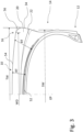
Figure 4 shows a detail of the cross-section of the tyre shown inFig. 3 at the location of the tread section of the tyre. - The presented invention relates to a
pneumatic tyre 100 which is made of rubber material and suitable for use in forestry, especially in forestry vehicles and equipment. - The
tyre 100 is adapted to be in contact with the ground surface. Thetyre 100 is to be filled with a gas, such as air, e.g. by means of an inner tube or without it. A ground-engaging tread section 10 is provided on the circumference of thetyre 100 and constitutes an endless surface in a circumferential direction C of thetyre 100, making it possible for thetyre 100 to roll forward. - With reference to
Figs. 1 to 4 , thetyre 100 comprises the ground-engaging tread section 10, a pair ofbead sections 12, and a pair ofsidewall sections 14. - The
tyre 100 when uninflated and separated from a wheel rim, exhibits the cross-sectional shape as shown inFigs. 3 and4 . The typical operating pressure for thetyre 100 according to the invention may be 6 bar (i.e. 600 kPa or 6 kN/m2 or 87 psi) or lower. - The
tread section 10 extends around thetyre 100 in the circumferential direction C, thetread section 10 defining an imaginary equatorial plane EP that is perpendicular to axial directions A and passes through acentre region 40 of thetread section 10. - The axial direction A refers to directions that extend from the equatorial plane EP and are parallel to the axis of rotation CL of the tyre, i.e. a centreline CL defined by the circular shape of the
tyre 100. The equatorial plane EP refers to a plane perpendicular to the axis of rotation CL and passing through thecentre region 40, preferably the centre of thetread section 10. - The
bead sections 12 are located on two opposite sides of thetyre 100. Preferably, thebead sections 12 are adapted to secure thetyre 100 to the wheel rim. - The
sidewall sections 14 are located on two opposite sides of thetyre 100. Eachsidewall section 14 extends between therespective bead section 12 and thetread section 10. Thetread section 10 defines a pair ofshoulder regions 16 at lateral extremes of thetread section 10, eachshoulder region 16 being adjacent to therespective sidewall section 14. - The
tread section 10 comprises a tread design including raised portions of the tread, for example ribs, lugs, blocks, or combinations of two or more of these, the raised portions being separated by grooves. - A tread width TW constituting an overall width for the
tread section 10 in the axial direction A is defined by a pair of axiallyoutermost shoulder surfaces 34 at the lateral extremes of thetread section 10. For example, the tread width TW is preferably measured at an axially outermost point that is on theshoulder surface 34 or alternatively, at a point at an axially outermost edge of a chamfer or rounding 56 that is between thetread section 10 and theshoulder surface 34. These points correspond to each other in the example shown inFig. 4 . Alternatively, the tread width TW is measured at an axially outermost edge of thetread section 10, especially in a case in which there are no chamfers or roundings. This point is repesented by apoint 60 shown inFig. 4 , to which atread surface 54 of thetread section 10 may extend according to an example. - According to a preferred example, the axially
outermost shoulder surface 34 and the lateral extreme of thetread section 10 are defined by raised portions of the tread,e.g. lugs 20. - A sidewall width SW of the
tyre 100 in the axial direction A is defined by lateral extremes of the pair ofsidewall sections 14. Preferably, thesidewall section 14 extends to theshoulder surface 34. - According to an example, the sidewall width SW is at all points of the
sidewall 14 or mostly less than the tread width TW. For example, the ratio of the tread width TW to the sidewall width SW is from 1:1 to 1.2:1, i.e. 1.0, or more than 1.0. In such a case, thesidewall section 14 may constitute a rounding and/or a concave surface extending to theshoulder surface 34. - According to another example, the ratio of the tread width TW to the sidewall width SW is from 0.8:1 to 1:1, i.e. 1.0, or less than 1.0.
- The
tyre 100 further comprises acarcass 52 that is located radially inwards of thetread section 10. Thecarcass 52 constitutes a frame of thetyre 100 and may include a plurality of plies made of cords or threads. Preferably, the plies are arranged diagonally and cross each other to constitute a cross-ply tyre (i.e. a bias tyre). According to another example, the plies are arranged parallel to each other across thetyre 100 to constitute a radial-ply tyre (i.e. a radial tyre). - The cross-ply tyre may include a reinforcing breaker ply, e.g. a fabric or steel material, on the plies of the
carcass 52 under thetread section 10. The radial-ply tyre may include a rigid belt between thetread section 10 and thecarcass 52. Thetyre 100 may further comprise an inner liner that is located radially inwards of thecarcass 52, inside thetyre 100. - The
carcass 52 defines a toroidal shape extending between thebead sections 12. Beneath thetread section 10, with reference toFigs. 3 and4 , thecarcass 52 constitutes a convex shape in cross-section, i.e. on a plane that extends in the axial direction A and radially from the axis of rotation CL, thecarcass 52 extending symmetrically and axially in equal amounts on both sides of the equatorial plane EP. The convex shape bulges outwards radially and in relation to the axis of rotation CL. - According to an example, the radius of curvature of the convex shape of the
carcass 52 decreases with increasing distance from the equatorial plane EP. - The
tread section 10 comprises thetread surface 54 that is ground-engaging and radially outermost, and with reference toFigs. 3 and4 , constitutes a convex shape in cross-section, i.e. on the plane that extends in the axial direction A and radially from the axis of rotation CL, thetread surface 54 extending symmetrically and axially in equal amounts on both sides of the equatorial plane EP. The convex shape bulges outwards radially and in relation to the axis of rotation CL. In thecentre region 40, the convex shape may include a section with a substantially straight shape or a shape with a radius of curvature noticeably larger than the rest of the convex shape. - According to an example, the radius of curvature of the convex shape of the
tread surface 54 decreases with the increasing distance from the equatorial plane EP. - According to a preferred example, the convex shape of the
tread surface 54 gradually diverges from the convex shape of thecarcass 52 when, in the axial direction A, its distance from the equatorial plane EP increases. - The convex shapes diverge in the axial direction A. The convex shapes may continually diverge within a width WD that is defined by points that are on the
tread surface 54 on both sides of the equatorial plane EP. For example, with reference toFig. 4 , the width WD is measured at the above outermost edge of thetread section 10 or at an axially innermost edge of a chamfer or rounding 56 that is between thetread section 10 and theshoulder surface 34. This point is represented by apoint 64 shown inFig. 4 , to which point thetread surface 54 extends. - As an alternative to the example above, in the
centre region 40 within a distance from the equatorial plane EP, the convex shapes may be parallel to each other, the distance being 25% or 33% of the width WD. - According to an example, the
tread section 10 comprises at least in theshoulder regions 16 thelugs 20 between whichgrooves 38 extend laterally, across or at an angle to the circumferential direction C. - According to an example, the
lugs 20 extend at an angle differing from the above plane in such a way that the convex shape of thetread surface 54 is discontinued in the cross-sectional views ofFigs. 3 and4 . In that situation, the convex shape of thetread surface 54 is projected or mapped onto the above plane such that the convex shape is continuous inFigs. 3 and4 . When projecting or mapping, the radial distance of the convex shape in relation to the axis of rotation CL is maintained. The dimensions depicted in this disclosure relate to the above plane unless otherwise stated. - The
groove 38 defines a groove bottom 22 that according to an example extends to thesidewall section 14. According to an example, the groove bottom 22 constitutes a shape that is convex in cross-section, on the plane that extends in the axial direction A and radially from the axis of rotation CL, the groove bottom 22 extending on both sides of the equatorial plane EP, at least in theshoulder region 16. The shape of the groove bottom 22 bulges outwards radially and in relation to the axis of rotation CL. - According to a preferred example, the shape of the groove bottom 22 gradually diverges from the convex shape of the
carcass 52 when, in the axial direction A, its distance from the equatorial plane EP increases. - According to an example, the shape of the groove bottom 22 is at a distance from and follows the convex shape of the
tread surface 54, the shapes being substantially parallel. - The distance of the convex shape of the
tread surface 54 from the convex shape of thecarcass 52, in the above-mentioned plane, defines the thickness of and the amount of rubber material forming thetread section 10 and/or thelugs 20 of thetread section 10 defining thetread surface 54. - With the above increasing distance related to the diverging convex shapes, the thickness of the rubber material continually increases in the axial direction A.
- The gradual change in the thickness of the rubber material may be defined by distances RT between the convex shape of the
carcass 52 and the convex shape of thetread surface 54 in a direction normal or perpendicular to the convex shape of thecarcass 52. - According to an example, the thickness of the rubber material is defined by the distances RT at selected distances SD from the equatorial plane EP within the tread width TW. The selected distances SD define selected points SP along the convex shape of the
tread surface 54, the selected points SP being on thetread surface 54. Each selected distance SD is measured in the axial direction A. - The selected distance SD at its maximum is defined by the above point defining the overall tread width TW. Therefore, the selected distance SD at its maximum is 50% of the overall tread width TW. In the examples below and with reference to
Fig. 4 , the overall tread width TW is defined by the axiallyoutermost shoulder surface 34 at the lateral extreme of thetread section 10. - The selected distances SD may be presented in such a manner that each selected distance SD relating to one of the selected points SP is represented by a percentage of or a fraction of the maximum selected distance SD. Thus, the selected distance SD representing a point at the maximum selected distance SD is represented by "1.00" or "100%", and the selected point SP on the equatorial plane EP relates to the selected distance SD represented by "0.00" or "0%". The selected distance SD starting at the equatorial plane EP and extending halfway across the
tread section 10 in the axial direction A is represented by "0.50" or "50%". - The thickness of the rubber material and the distances RT are measured along straight lines each extending in the direction normal or perpendicular to the convex shape of the
carcass 52, each line extending through one of the selected points SP. - The thickness of the rubber material and the distance RT at each selected point SP may be represented as a ratio of the thickness at the selected point SP to the thickness at the selected point SP that is on the equatorial plane EP and represents the selected distance SD of "0%". The absolute value of the thickness and the distance RT at the selected distance SD of "0%" may be represented by "1.00" or "100%". The thickness and the distance RT may increase with the increasing selected distance SD and therefore, the thickness expressed by means of the above ratio may increase above "1.00" or "100%".
- With reference to
Figs. 3 and4 , according to a preferred example, the thickness of the rubber material, as defined above, is selected for thetyre 100 in the following manner: - at the selected distance SD of "0.00", the thickness is defined as 100% and constitutes a reference;
- at the selected distance SD of "0.67", the thickness is from 118% to 167%, or preferably from 130% to 155%, or more preferably from 138% to 151%, or is targeting 141%; and
- at the selected distance SD of "0.83", the thickness is from 144% to 203%, or preferably from 157% to 187%, or more preferably from 169% to 182%, or is targeting 172%.
- In the above preferred example, the thickness of the rubber material in the
shoulder region 16 may be almost double the thickness in thecentre region 40. - In the examples above and below in relation to the thickness of the rubber material, the first and second ranges take into consideration typical and preferred embodiments of the
tyre 100 according to the presented solution and the third range takes into consideration one prederred embodiment of thetyre 100 with reasonable manufacturing tolerances. - Additionally, according to an example and with reference to the example in
Fig. 4 , the thickness of the rubber material, as defined above, is selected for thetyre 100 in the following manner: - at the selected distance SD of "0.91", the thickness is from 160% to 225%, or preferably from 173% to 208%, or more preferably from 187% to 202%, or is targeting 191%.
- In the above example, the thickness of the rubber material in the
shoulder region 16 may be twice the thickness in thecentre region 40. - Additionally, with reference to the example in
Fig. 4 , when there is the chamfer or rounding 56 between thetread section 10 and theshoulder surface 34, the selected point SP at the selected distance SD of "1.00" is represented by animaginary point 62 that is above the chamfer or rounding 56 at the location in which animaginary extension 58 of the convex shape of thetread surface 54 reaches the selected distance SD of "1.00". Theimaginary extension 58 implements the curvature defined by the convex shape of thetread surface 54. - Therefore, in the example of
Fig. 4 , at the selected distance SD of "1.00", the thickness of the rubber material may be from 180% to 258%, or preferably from 196% to 234%, or more preferably from 211% to 227%, or is targeting 215%. - In this example, the thickness represents the maximum thickness of the rubber material that can be approached depending on the size of the chamfer or rounding 56, e.g. its radius of curvature, selected for the
tyre 100. In the example, the thickness of the rubber material in theshoulder region 16 may be twice the thickness in thecentre region 40 or more. - Additionally, with reference to the example in
Fig. 4 and relating to the convex shape of thetread surface 54 and the convex shape of thecarcass 52 in thecentre region 40, as explained above, the thickness of the rubber material, as defined above, may preferably be selected for thetyre 100 in the following manner: - at the selected distance SD of "0.17", the thickness is from 95% to 120%, or preferably 97% to 115%, or more preferably 99% to 110%, or is targeting 102%; and/or
- at the selected distance SD of "0.33", the thickness is from 100% to 124%, or preferably from 103% to 120%, or more preferably from 105% to 116%, or is targeting 108%; and/or
- at the selected distance SD of "0.50", the thickness is from 105% to 124%, or preferably from 112% to 131%, or more preferably from 117% to 129%, or is targeting 120%.
- In the above example parallel, straight, or convex shapes in the centre region, possibly with a large radius of curvature, are enabled.
- According to an example, the distance of the convex shape of the groove bottom 22 from the convex shape of the
carcass 52, in the above-mentioned plane, defines the thickness of and the amount of rubber material at thegrooves 38 between the lugs 20. The thickness and the distance are measured along the straight lines explained above, each line extending through one of the selected points SP. - With reference to
Figs. 3 and4 , according to a preferred example, the thickness at thegroove 38, as defined above, may be selected for thetyre 100 in the following manner: - at the selected distance SD of "0.00", the thickness is from 19% to 35%, or preferably from 21% to 33%, of the distance RT at the corresponding selected point SP; and/or
- at the selected distance SD of "0.67", the thickness is from 26% to 44%, or preferably from 28% to 41%, of the distance RT at the corresponding selected point SP; and/or
- at the selected distance SD of "0.83", the thickness is from 33% to 51%, or preferably from 35% to 48%, of the distance RT at the correspond corresponding point SP; and/or
- at the selected distance SD of "0.91", the thickness is from 31% to 50%, or preferably from 32% to 47%, of the distance RT at the correspond corresponding point SP.
- Additionally, with reference to the example in
Fig. 4 as explained above in relation to theimaginary point 60, when there is the chamfer or rounding 56 between thetread section 10 and theshoulder surface 34, at the selected distance SD of "1.00", the thickness of the rubber material at thegroove 38 may be from 33% to 52%, or preferably from 34% to 50%, of the distance RT at the corresponding selected point SP. In this example, the thickness relates to the actual thickness of the rubber material. - According to an example, the chamfer or rounding 56 begins at the selected distance SD of "0.91" or between "0.91" and "1.00".
- Additionally, with reference to the example in
Fig. 4 and relating to the convex shape of thetread surface 54 and the convex shape of thecarcass 52 in thecentre region 40, as explained above, at the selected distance SD of "0.17", the thickness of the rubber material at thegroove 38 may preferably be selected for thetyre 100 in the following manner: - at the selected distance SD of "0.17", the thickness is from 19% to 34%, or preferably from 21% to 32%, of the distance RT at the corresponding selected point SP; and/or
- at the selected distance SD of "0.33", the thickness is from 24% to 39%, or preferably from 26% to 37%, of the distance RT at the corresponding selected point SP; and/or
- at the selected distance SD of "0.50", the thickness is from 27% to 42%, or preferably from 29% to 41%, of the distance RT at the correspond corresponding point SP.
- According to an example, the thickness of the rubber material and the distance RT at the selected distance SD of "0.00" is 50 mm to 100 mm, or more preferably 60mm to 75mm.
- According to an example, the diameter of the
tyre 100 in the equatorial plane EP is 1340 mm to 1525 mm. According to an example, the tread width TW and/or the sidewall width SW is 700 mm to 900 mm. - According to an example, the nominal section width is 750 mm, the aspect ratio is 55 percent, and the rim diameter is 26.5 inches. According to another example, the nominal section width is 710 mm, the aspect ratio is 45 percent, and the rim diameter is 26.5 inches.
- According to an example, the radius of curvature of the convex shape of the
carcass 52 is 500 mm to 800 mm in thecentre region 40, the radius of curvature decreasing with the increasing distance from the equatorial plane EP. - According to an example, the radius of curvature of the convex shape of the
tread surface 54 is 2000 mm to 2600 mm at least in thecentre region 40. - According to an example, the radius of curvature of the shape of the groove bottom 22 is 1200 mm to 1600 mm in the
centre region 40, the radius of curvature decreasing with the increasing distance from the equatorial plane EP. - With reference to the example in
Figs. 1 and2 , thetread section 10 comprises alug row 50 on both sides of the equatorial plane EP, eachlug row 50 includinglugs 20 and extending in the circumferential direction C. Eachlug row 50 comprises a series oflugs 20 that are spaced along the circumferential direction C and definegrooves 38 located between thelugs 20 and defining a groove bottom 22 (seeFig. 4 ). According to an example, the groove bottom 22 extends to thesidewall section 14. - The
lugs 20 extend radially from the level of thegroove bottom 22. - According to an example, each
lug 20 is oriented obliquely with respect to the circumferential direction C. Thelug 20 extends obliquely with respect to the axial direction A from thecentre region 40 to theshoulder region 16. - According to an example, in the
shoulder region 16, thelug 20 includes a branch that is connected to thelug 20 or separated from thelug 20 by a shallow groove. Additionally, agroove 38 may separate the branch and the trunk of thelug 20. The shallow groove or the separatinggroove 38 may extend to thesidewall section 14. - According to an example, the
lugs 20 extend towards or to thecentre region 40. Additionally, according to a further example, thelugs 20 may extend across the equatorial plane EP. - According to an example, the
lugs 20 constitute separate blocks encircled by thegrooves 38 of thetread section 10. According to an example, thegrooves 38 of thetread section 10 are connected to each other. Alternatively, according to an example, thelugs 20 are connected to each other in thecentre region 40. - According to an example, see
Figs 1 and2 , thelugs 20 alternate in thecentre region 40 in such a way that everyother lug 20 belongs to one of thelug rows 50 and everyother lug 20 belongs to theother lug row 50. - According to an example, in the
centre region 40, thelug 20 may include an end section directed in the axial direction A towards the opposite side of thetread section 10. According to another example, in thecentre region 40, thetread section 10 may include one or more blocks as extensions of thelugs 20, the block being separated from thelug 20 by a shallow groove. - The depth of the shallow groove may be at the most 20% to 30% of the height of the
lug 20 with respect to thegroove bottom 22. - Preferably, in the
tread section 10, the percentage of the area covered by thegrooves 38 is at the most from 25% to 40% of the area covered by both thegrooves 38 and thelugs 20. Preferably, thelug 20 is oriented obliquely at an angle of 30 degrees to 60 degrees with respect to the circumferential direction C. - Preferably, the
centre region 40 covers in the axial direction A not more than 5% to 20% of the width of thetread section 10. - According to an example, as shown in
Figs. 2 and3 , eachlug 20 in addition to the axiallyoutermost shoulder surface 34 comprises a radially outermost surface constituting thetread surface 54. Theshoulder surface 34 is oriented transversally in relation to thetread surface 54. - The the
tread surface 54 forms the top surface of thelug 20 and theshoulder surface 34 forms the end surface of thelug 20. Theshoulder surface 34 may form an integral part of the surface of thesidewall section 14. According to an example, theshoulder surface 34 unites with the surface of thesidewall section 14 in a grooveless or seamless manner. - According to an example, as shown in
Fig. 3 , theshoulder surface 34 is separated from thetread surface 54 by an edge of thelug 20, by a chamber, or by a rounding, e.g. the chamfer or rounding 56. - The above-mentioned forestry vehicle may comprise a frame having two opposite sides and being wheeled for propulsion of the forestry vehicle. On each side of the frame, there may be two or more wheel assemblies each including a tyre. According to an example, a pair of wheel assemblies may be installed to a bogie axle assembly of the frame. The wheel assembly may comprise a wheel rim on which the tyre is installed and the wheel assembly is, e.g. by means of the wheel rim, connectable to the frame, e.g. to a wheel mount on the frame. The bogie axle assembly may include the wheel mount.
- The frame of the forestry vehicle may be articulated. A cabin with an operator's station, an engine and an articulated boom may be attached to the frame. A tool for processing tree stems and/or handling logs may be attached to an end of the boom. The tool may be e.g. a felling head, a harvester head, or a timber grapple. The forestry vehicle may include a loading space supported on the frame for transporting logs.
- It is to be understood that examples of the disclosed invention are not limited to the structures disclosed herein, but may be extended to equivalents thereof as would be recognized by those skilled in the relevant art and without departing from the scope of the appended claims.
- It should also be understood that terminology employed herein is used for the purpose of describing particular examples only and is not intended to be limiting. Reference throughout this specification to "an example" means that a particular feature, structure, or characteristic described in connection with the example is included in at least one example of the present invention. Especially, in the examples above, when referring to a property of e.g. a single lug then all functionally corresponding lugs may include the same property.
- The verbs "to comprise" and "to include" are used in this specification as open limitations that neither exclude nor require the existence of also un-recited features. Furthermore, it is to be understood that the use of "a" or "an", i.e. a singular form, throughout this document does not exclude a plurality, unless where specifically mentioned.
Claims (15)
- A pneumatic tyre of rubber material for forestry vehicles, the tyre (100) comprising:- a ground-engaging tread section (10) extending around the tyre in the circumferential direction (C) of the tyre, wherein the tread section defines an imaginary equatorial plane (EP) that is perpendicular to an axial direction (A) of the tyre and passes through a centre region (40) of the tread section, and wherein the tread section (10) applies a tread design including raised portions of the tread section (10) that are separated by grooves (38);- a pair of shoulder regions (16) at the lateral extremes of the tread section (10) and including axially outermost shoulder surfaces (34) defining, in the axial direction (A), an overall tread width (TW) and a maximum selected distance (SD) from the equatorial plane (EP);- a carcass (52) within the rubber material, located radially inwards of the tread section (10), wherein the carcass (52) defines a convex shape in cross-section of the tyre, bulging radially outwards;- a ground-engaging, radially outermost tread surface (54) included in the tread section (10), wherein the tread surface (54) defines a convex shape in cross-section of the tyre, bulging radially outwards;- wherein a thickness of the rubber material forming the tread section (10) is defined at selected points (SP) on the tread surface (54), the selected points (SP) being, in the axial direction (A), at selected distances (SD) from the equatorial plane (EP), wherein the thickness is defined by distances (RT) between the convex shapes, measured along imaginary lines each extending in a direction normal to the convex shape of the carcass (52) and via one of the selected points (SP);- wherein, at a first selected distance (SD) at the equatorial plane (EP) at a first selected point (SP), the thickness is defined as 100%;characterized in that- at a selected distance (SD) of 67% of the maximum selected distance (SD), the thickness is defined as from 118% to 167%, or preferably from 130% to 155%, or more preferably from 138% to 151%, of the thickness at the first selected point (SP); and- at a selected distance (SD) of 83% of the maximum selected distance (SD), the thickness is defined as from 144% to 203%, or preferably from 157% to 187%, or more preferably from 169% to 182%, of the thickness at the first selected point (SP).
- The tyre according to claim 1, wherein- at a selected distance (SD) of 91% of the maximum selected distance (SD), the thickness is defined as from 160% to 225%, or preferably from 173% to 208%, or more preferably from 187% to 202%, of the thickness at the first selected point (SP).
- The tyre according to claim 1 or 2, wherein- at a selected distance (SD) of 100% of the maximum selected distance (SD) at a second selected point (SP), the thickness is defined as from 180% to 258%, or preferably from 196% to 234%, or more preferably from 211% to 227%, of the thickness at the first selected point (SP), and- the second selected point (SP) is represented by an imaginary point (62) that is above a chamfer or rounding (56) at a location in which an imaginary extension (58) of the convex shape of the tread surface (54) reaches the maximum selected distance (SD).
- The tyre according to any one of claims 1 to 3, wherein- at a selected distance (SD) of 17% of the maximum selected distance (SD) the thickness is defined as from 95% to 120%, or preferably 97% to 115%, or more preferably 99% to 110%, of the thickness at the first selected point (SP); and/or- at a selected distance (SD) of 33% of the maximum selected distance (SD), the thickness is defined as from 100% to 124%, or preferably from 103% to 120%, or more preferably from 105% to 116%, of the thickness at the first selected point (SP); and/or- at a selected distance (SD) of 50% of the maximum selected distance (SD), the thickness is defined as from 105% to 124%, or preferably from 112% to 131%, or more preferably from 117% to 129%, of the thickness at the first selected point (SP).
- The tyre according to any one of claims 1 to 4, wherein a thickness of the rubber material at the groove (38) is defined in the following manner:- at the first selected distance (SD), the thickness is from 19% to 35%, or preferably from 21% to 33%, of the thickness of the rubber material at the tread surface (54) and the first selected point (SP); and/or- at the selected distance (SD) of 17%, the thickness is from 19% to 34%, or preferably from 21% to 32%, of the thickness of the rubber material at the tread surface (54); and/or- at the selected distance (SD) of 33%, the thickness is from 24% to 39%, or preferably from 26% to 37%, of the thickness of the rubber material at the second selected point (SP); and/or- at the selected distance (SD) of 50%, the thickness is from 27% to 42%, or preferably from 29% to 41%, of the thickness of the rubber material at the third selected point (SP); and/or- at the selected distance (SD) of 67%, the thickness is from 26% to 44%, or preferably from 28% to 41%, of the thickness of the rubber material at the tread surface (54) and/or;- at the selected distance (SD) of 83%, the thickness is from 33% to 51%, or preferably from 35% to 48%, of the thickness of the rubber material at the tread surface (54); and/or- at the selected distance (SD) of 91%, the thickness is from 31% to 50%, or preferably from 32% to 47%, of the thickness of the rubber material at the tread surface (54).
- The tyre according to any one of claims 1 to 5, wherein the groove (38) defines a groove bottom (22) that defines a convex shape in cross-section of the tyre, the convex shape following the convex shape of the tread surface (54) at a distance, the convex shapes being substantially parallel.
- The tyre according to any one of claims 1 to 6, wherein, in the axial direction (A), the convex shape of the tread surface (54) gradually diverges from the convex shape of the carcass (52) when the distance to the equatorial plane (EP) increases.
- The tyre according to any one of claims 1 to 7, wherein the tyre further comprises:- a pair of bead sections (12) adapted to secure the tyre to a wheel rim, located on two opposite sides of the tyre; and- a pair of sidewall sections (14), located on two opposite sides of the tyre, wherein each sidewall section extends between the respective bead section and the tread section,- wherein a sidewall width (SW) of the tyre (100) in the axial direction (A) is defined by lateral extremes of the pair of sidewall sections (14), and wherein the ratio of the tread width (TW) to the sidewall width (SW) is more than 1.0.
- The tyre according to any one of claims 1 to 8, wherein the thickness of the rubber material at the first selected point (SP) is 50 mm to 100 mm, or more preferably 60mm to 75mm, and/or the diameter of the tyre in the equatorial plane (EP) is 1340 mm to 1525 mm, and/or the tread width (TW) is 700 mm to 900 mm.
- The tyre according to any one of claims 1 to 9, wherein the tyre (100) is a cross-ply tire.
- The tyre according to any one of claims 1 to 10, wherein the tread section (10) includes at least in the shoulder region (16) raised portions in the form of lugs (20) between which the grooves (38) extend laterally, across or at an angle to the circumferential direction (C), the grooves (38) extending to the sidewall section (14).
- The tyre according to claim 11, wherein the lugs (20) extend to the centre region (40) in which the lugs are connected to each other or separated by the grooves (38).
- The tyre according to claim 11 or 12, wherein- the tread section comprises a lug row (50) on both sides of the equatorial plane (EP) and each lug row extends in the circumferential direction (C);- each lug row (50) comprises a series of the lugs (20) that are spaced along the circumferential direction and define the grooves (38) located between the lugs.
- The tyre according to claim 13, wherein the lugs (20) alternate in the centre region (40) in such a way that every other lug is a lug of one of the lug rows (50) and every other lug is a lug of the other one of the lug rows.
- The tyre according to any one of claims 11 to 14, wherein the tread section (10) includes in the centre region (10) one or more blocks as extensions of the lugs (20).
Priority Applications (1)
| Application Number | Priority Date | Filing Date | Title |
|---|---|---|---|
| EP23175895.4A EP4470795B1 (en) | 2023-05-29 | 2023-05-29 | Pneumatic tyre of rubber material for forestry vehicles |
Applications Claiming Priority (1)
| Application Number | Priority Date | Filing Date | Title |
|---|---|---|---|
| EP23175895.4A EP4470795B1 (en) | 2023-05-29 | 2023-05-29 | Pneumatic tyre of rubber material for forestry vehicles |
Publications (3)
| Publication Number | Publication Date |
|---|---|
| EP4470795A1 true EP4470795A1 (en) | 2024-12-04 |
| EP4470795B1 EP4470795B1 (en) | 2026-01-28 |
| EP4470795C0 EP4470795C0 (en) | 2026-01-28 |
Family
ID=86605787
Family Applications (1)
| Application Number | Title | Priority Date | Filing Date |
|---|---|---|---|
| EP23175895.4A Active EP4470795B1 (en) | 2023-05-29 | 2023-05-29 | Pneumatic tyre of rubber material for forestry vehicles |
Country Status (1)
| Country | Link |
|---|---|
| EP (1) | EP4470795B1 (en) |
Citations (7)
| Publication number | Priority date | Publication date | Assignee | Title |
|---|---|---|---|---|
| US3939890A (en) * | 1974-04-23 | 1976-02-24 | Bridgestone Tire Company, Ltd. | Wide base type pneumatic tire for construction vehicle |
| US4222424A (en) * | 1977-12-28 | 1980-09-16 | Bridgestone Tire Company Limited | Lug tires with uniform base rubber gauge |
| JPH0632110U (en) * | 1992-10-05 | 1994-04-26 | オーツタイヤ株式会社 | Agricultural tire with rug |
| JP2008114756A (en) * | 2006-11-06 | 2008-05-22 | Bridgestone Corp | Tire for agricultural machine |
| EP3412475A1 (en) | 2017-06-08 | 2018-12-12 | Nokian Raskaat Renkaat Oy | Pneumatic vehicle tyre |
| EP3738791A1 (en) | 2019-05-14 | 2020-11-18 | Nokian Raskaat Renkaat Oy | Pneumatic vehicle tyre for forestry use |
| EP3925867A1 (en) | 2020-06-18 | 2021-12-22 | Nokian Raskaat Renkaat Oy | Pneumatic vehicle tyre for forestry use |
-
2023
- 2023-05-29 EP EP23175895.4A patent/EP4470795B1/en active Active
Patent Citations (7)
| Publication number | Priority date | Publication date | Assignee | Title |
|---|---|---|---|---|
| US3939890A (en) * | 1974-04-23 | 1976-02-24 | Bridgestone Tire Company, Ltd. | Wide base type pneumatic tire for construction vehicle |
| US4222424A (en) * | 1977-12-28 | 1980-09-16 | Bridgestone Tire Company Limited | Lug tires with uniform base rubber gauge |
| JPH0632110U (en) * | 1992-10-05 | 1994-04-26 | オーツタイヤ株式会社 | Agricultural tire with rug |
| JP2008114756A (en) * | 2006-11-06 | 2008-05-22 | Bridgestone Corp | Tire for agricultural machine |
| EP3412475A1 (en) | 2017-06-08 | 2018-12-12 | Nokian Raskaat Renkaat Oy | Pneumatic vehicle tyre |
| EP3738791A1 (en) | 2019-05-14 | 2020-11-18 | Nokian Raskaat Renkaat Oy | Pneumatic vehicle tyre for forestry use |
| EP3925867A1 (en) | 2020-06-18 | 2021-12-22 | Nokian Raskaat Renkaat Oy | Pneumatic vehicle tyre for forestry use |
Also Published As
| Publication number | Publication date |
|---|---|
| EP4470795B1 (en) | 2026-01-28 |
| EP4470795C0 (en) | 2026-01-28 |
Similar Documents
| Publication | Publication Date | Title |
|---|---|---|
| CA2674977C (en) | Heavy duty tire | |
| US7972550B2 (en) | Method of increasing the load capacity of a radial tire | |
| EP0510465B1 (en) | A pneumatic agricultural or logging tire | |
| US8678055B2 (en) | Pneumatic tire | |
| EP3738791B1 (en) | Pneumatic vehicle tyre for forestry use | |
| US20130030658A1 (en) | Adjustable tire pressure system and method | |
| US20160159162A1 (en) | Pneumatic tire for use on row-crop field sprayers and other like farm machinery | |
| US6209602B1 (en) | Industrial service agricultural tire | |
| US6941990B2 (en) | Off-road tires having sidewall anti-puncture pads | |
| US4282914A (en) | Pneumatic tire for heavy load vehicles | |
| US7503360B2 (en) | Radial farm tire for high clearance sprayers | |
| WO2009057780A1 (en) | Pneumatic radial tire | |
| EP4470795A1 (en) | Pneumatic tyre of rubber material for forestry vehicles | |
| EP0703102B1 (en) | Motorcycle radial tyre | |
| US11420478B2 (en) | Tyre | |
| US20190054770A1 (en) | Off the road tire | |
| EP0958151B1 (en) | Industrial service agricultural tire | |
| AU2017228598A1 (en) | Heavy duty tyre and tread | |
| US20220250415A1 (en) | Heavy duty tire | |
| US20200198406A1 (en) | Tread for a pneumatic tire | |
| EP3925867B1 (en) | Pneumatic vehicle tyre for forestry use | |
| US6125898A (en) | Motor-cycle radial tire | |
| EP1017574B1 (en) | High aspect agricultural or off-road tire | |
| JP3400005B2 (en) | Pneumatic radial tire | |
| EP0921955B1 (en) | Industrial service agricultural tire |
Legal Events
| Date | Code | Title | Description |
|---|---|---|---|
| PUAI | Public reference made under article 153(3) epc to a published international application that has entered the european phase |
Free format text: ORIGINAL CODE: 0009012 |
|
| STAA | Information on the status of an ep patent application or granted ep patent |
Free format text: STATUS: THE APPLICATION HAS BEEN PUBLISHED |
|
| AK | Designated contracting states |
Kind code of ref document: A1 Designated state(s): AL AT BE BG CH CY CZ DE DK EE ES FI FR GB GR HR HU IE IS IT LI LT LU LV MC ME MK MT NL NO PL PT RO RS SE SI SK SM TR |
|
| STAA | Information on the status of an ep patent application or granted ep patent |
Free format text: STATUS: REQUEST FOR EXAMINATION WAS MADE |
|
| 17P | Request for examination filed |
Effective date: 20250225 |
|
| GRAP | Despatch of communication of intention to grant a patent |
Free format text: ORIGINAL CODE: EPIDOSNIGR1 |
|
| STAA | Information on the status of an ep patent application or granted ep patent |
Free format text: STATUS: GRANT OF PATENT IS INTENDED |
|
| INTG | Intention to grant announced |
Effective date: 20250917 |
|
| GRAS | Grant fee paid |
Free format text: ORIGINAL CODE: EPIDOSNIGR3 |
|
| GRAA | (expected) grant |
Free format text: ORIGINAL CODE: 0009210 |
|
| STAA | Information on the status of an ep patent application or granted ep patent |
Free format text: STATUS: THE PATENT HAS BEEN GRANTED |
|
| AK | Designated contracting states |
Kind code of ref document: B1 Designated state(s): AL AT BE BG CH CY CZ DE DK EE ES FI FR GB GR HR HU IE IS IT LI LT LU LV MC ME MK MT NL NO PL PT RO RS SE SI SK SM TR |
|
| REG | Reference to a national code |
Ref country code: CH Ref legal event code: F10 Free format text: ST27 STATUS EVENT CODE: U-0-0-F10-F00 (AS PROVIDED BY THE NATIONAL OFFICE) Effective date: 20260128 Ref country code: GB Ref legal event code: FG4D |
|
| REG | Reference to a national code |
Ref country code: DE Ref legal event code: R096 Ref document number: 602023011173 Country of ref document: DE |
|
| REG | Reference to a national code |
Ref country code: IE Ref legal event code: FG4D |
|
| U01 | Request for unitary effect filed |
Effective date: 20260206 |
|
| U07 | Unitary effect registered |
Designated state(s): AT BE BG DE DK EE FI FR IT LT LU LV MT NL PT RO SE SI Effective date: 20260217 |