EP4470789A1 - Method of rigidly bonding together two plates for forming a frame for a printer - Google Patents
Method of rigidly bonding together two plates for forming a frame for a printer Download PDFInfo
- Publication number
- EP4470789A1 EP4470789A1 EP23176508.2A EP23176508A EP4470789A1 EP 4470789 A1 EP4470789 A1 EP 4470789A1 EP 23176508 A EP23176508 A EP 23176508A EP 4470789 A1 EP4470789 A1 EP 4470789A1
- Authority
- EP
- European Patent Office
- Prior art keywords
- plates
- receiving member
- receiving
- recess
- receiving channel
- Prior art date
- Legal status (The legal status is an assumption and is not a legal conclusion. Google has not performed a legal analysis and makes no representation as to the accuracy of the status listed.)
- Pending
Links
Images




Classifications
-
- B—PERFORMING OPERATIONS; TRANSPORTING
- B41—PRINTING; LINING MACHINES; TYPEWRITERS; STAMPS
- B41J—TYPEWRITERS; SELECTIVE PRINTING MECHANISMS, i.e. MECHANISMS PRINTING OTHERWISE THAN FROM A FORME; CORRECTION OF TYPOGRAPHICAL ERRORS
- B41J29/00—Details of, or accessories for, typewriters or selective printing mechanisms not otherwise provided for
- B41J29/02—Framework
-
- G—PHYSICS
- G03—PHOTOGRAPHY; CINEMATOGRAPHY; ANALOGOUS TECHNIQUES USING WAVES OTHER THAN OPTICAL WAVES; ELECTROGRAPHY; HOLOGRAPHY
- G03G—ELECTROGRAPHY; ELECTROPHOTOGRAPHY; MAGNETOGRAPHY
- G03G21/00—Arrangements not provided for by groups G03G13/00 - G03G19/00, e.g. cleaning, elimination of residual charge
- G03G21/16—Mechanical means for facilitating the maintenance of the apparatus, e.g. modular arrangements
- G03G21/1604—Arrangement or disposition of the entire apparatus
- G03G21/1619—Frame structures
Definitions
- the invention relates to a method for bonding two plates perpendicularly to one another and to a frame formed by such a method.
- Printers comprise a print assembly for forming an image an a print medium.
- the print assembly comprises a plurality of printheads for jetting droplets of ink onto the print medium.
- the image quality is determined by the accuracy wherein the print medium is positioned with respect to the print assembly.
- the print assembly and/or a transport device for moving the print medium is generally supported on a frame for the printer. When the rigidity is low, the print medium may not be positioned accurately with respect to the print assembly, reducing the image quality. It is known to form part of a frame by positioning two metal plates perpendicular to one another and bonding these together at a bent portion of one of the plates.
- the bent portion is generally an edge portion of one of the plates bent at a right angle, wherein one or more openings have been provided. Said openings are aligned with openings in another plate and a bonding member, such as a rivet, is inserted through the openings to hold the plates together. Instabilities in the frame may result in inaccurate positioning of the print medium with respect to the print assembly, which may affect the image quality of the printed image.
- a method for bonding two plates perpendicularly to one another according to claim 1 and a frame according to claim 12 comprises the steps of:
- the rigidity of the frame is improved.
- the second one of the plates is positioned perpendicular against the first one of the plates, so that the bonding member extends through the insertion opening into the receiving channel, which is within the plane of the first one of the plates. Bending of the second one of the plates due to the bonding force is reduced or prevented, since the bonding force is exerted on a line which overlaps with the first edge of the first one of the plates.
- the bonding member engages the second one of the plates, where the second one of the plates is supported by the first edge of the first one of the plates, which prevents or reduces bending of the second one of the plates at the bonding member.
- a rigid frame can be formed from two plates in a relatively simple and low-costs manner.
- the higher rigidity of the frame when applied in a transport device and/or print assembly for a printer would reduce unintended movement of a print medium with respect to the print assembly, which would result in a more accurate positioning of the image on the print medium. This increases the image quality.
- the object of the present invention has been achieved.
- the recess is delimited by receiving member holding elements for holding the receiving member onto the first one of the plates.
- the receiving member with the receiving channel is connected to the first plate via the receiving member holding elements.
- the connection is preferably rigid.
- One or more receiving member holding elements form or define a portion of the edge of the recess.
- the receiving member holding elements are formed from the first one of the plates and extend parallel to the respective edge.
- the receiving member holding elements are integrally formed from the first one of the plates, for example by cutting the respective plate.
- the receiving member is formed from the first one of the plates.
- the receiving member is in this embodiment integrally formed with the first one of the plates, for example by cutting the respective plate.
- the receiving member is formed of plate material.
- the first one of the plates is cut, such that receiving member is formed connected to the first one of the plates via the receiving member holding elements.
- the receiving member holding elements are preferably formed of plate material as well.
- the recess is formed by at least partially bending the receiving member out of a plane defined by the first one of the plates.
- the plate material of the receiving member is bent out of the plane of the first one of the plates to form a three-dimensional structure, wherein a portion of the receiving member extends above and/or below the plane of the first one of the plates.
- the receiving member may retain its shape, but the receiving member holding elements are deformed. Therein, the receiving member holding elements and/or at least a portion of the receiving member may be deformed, by e.g. bending or twisting, to move the receiving member out of the respective plane.
- the receiving member holding elements comprise twist elements connected at opposite sides of the receiving member to the first one of the plates, such that the receiving member is rotatable out of the plane around an axis defined by the receiving member holding elements.
- the receiving member is held to the first plate, such that it can be rotated, wherein the receiving member holding elements become twisted.
- the twisting deformation of the receiving member holding elements is permanent, such that the receiving member remains in its rotated, final position.
- the receiving channel is defined by a central opening of a ring element of the receiving member.
- the receiving member comprises at least two adjacent strips formed of the first one of the plates, each strip connected on opposite sides to the first one of the plates via the receiving member holding elements, such that the strips may be bent out of the plane in opposite directions to form the receiving channel.
- the receiving channel is formed by the alternatingly bent strips.
- at least three strips are provided in a row, wherein the strips have similar dimensions.
- the strips preferably extend parallel to the first edge and are at either end connected to the first one of the plates via a receiving member holding element.
- the strips are permanently deformed by out-of-plane bending by e.g. debossing. Each strips forms an arch, wherein each strip is in an orientation which is rotated 180° with respect to a neighboring strip.
- the receiving member comprises a body defining the receiving channel and grooves for receiving the receiving member holding elements for mounting the body onto the first one of the plates.
- the receiving member may be formed separate from the first one of the plates.
- the body has grooves running parallel to the receiving channel on the outside of the body. Each groove has a length less than that of the receiving channel, so that each groove comprises an end wall in the direction of the receiving channel.
- the receiving member holding elements are formed by protruding sections of the first one of the plates, which are inserted into the grooves as the body is moved through the recess perpendicular to the first edge. When the receiving member holding elements contact the end walls, the body is restricted from moving further in the direction of the second one of the plates.
- the plates can be secured together by means of a bonding member.
- the plates are formed of metal, such as steel.
- the method further comprises the step of forming a printer frame from the bonded plates and mounting the printer frame in a printer.
- the printer comprises a transport device for positioning a print medium with respect to a printing assembly, for example an endless belt conveyor.
- the transport device is mounted on the frame formed of the bonded, so that it is rigidly secured, reducing unintended displacement of the print medium with respect to the print assembly.
- the receiving member holding elements and at least part of the recess are formed by cutting the first one of the plate.
- the cutting may be performed by drilling, milling, hydrocutting, laser cutting, punching, or any other suitable cutting technique.
- the recess is cut into the first one of the plates as an opening.
- the receiving member holding elements are also formed by removing plate material around them by cutting.
- the bonding member is a rivet, preferably a blind rivet.
- the present invention further relates to a frame for a printer comprising a pair of plates bonded together, wherein a first one of the plates comprises a receiving member provided in a recess adjacent an edge of the first one of plates, the receiving member being connected to the first one of the plates via receiving member holding elements on opposite sides of the receiving member, such that such that a center of the receiving channel is positioned in a plane defined by the first one of the plates and the receiving channel extends substantially perpendicular to the respective edge of the first one of the plates, wherein a second one of the plates is positioned against the respective edge of the first one of the plates at a substantially right angle, such that an insertion opening is aligned with the receiving channel, and wherein a bonding member is inserted via the insertion opening into the receiving channel to hold the two plates together.
- the frame with the bonded plates may be formed by any of the above described embodiments.
- the frame is applied in a printer, preferably to support a transport device for moving print media past a print assembly.
- the receiving channel extends between the recess and the first edge.
- the central axis of the receiving channel is positioned between the recess and the first edge within the plane of the first one of the plates.
- the central axis is perpendicular to the first edge.
- the recess comprises a free space on an opposite side of the receiving member with respect to the respective edge.
- the recess forms a free space wherein the bonding member may extend during the mounting of the bonding member.
- a rivet, bolt, screw, etc. requires an open space where it exits the receiving channel for forming the wider end of the holding member, which prevents it from travelling back through the receiving channel.
- the bonding member is a rivet, specifically a blind rivet.
- the receiving member holding elements define a portion of the edge of the recess. In another embodiment, the receiving member holding elements are formed from the first one of the plates.
- FIG. 1 shows schematically an embodiment of a printer 1 according to the present invention.
- the printer 1 for purposes of explanation, is divided into an output section 5, a print engine and control section 3, a local user interface 7 and an input section 4.
- the individual components therein may be mounted on a common frame or separate frames may be applied per section or component.
- the frames are preferably formed of a plurality of metal plates, which are bonded together under an angle by means of bonding member, such as a rivet or screw. While a specific printer is shown and described, the disclosed embodiments may be used with other types of printer such as an ink jet print system, an electrographic print system, etc.
- the output section 5 comprises a first output holder 52 for holding printed image receiving material, for example a plurality of sheets.
- the output section 5 may comprise a second output holder 55. While 2 output holders are illustrated in FIG. 1 , the number of output holders may include one, two, three or more output holders.
- the printed image receiving material is transported from the print engine and control section 3 via an inlet 53 to the output section 5.
- first guiding means 54 are activated in order to eject the plurality of sheets in the first output holder 52 outwards to a first external output holder 51.
- second guiding means 56 are activated in order to eject the plurality of sheets in the second output holder 55 outwards to a second external output holder 57.
- the output section 5 is digitally connected by means of a cable 60 to the print engine and control section 3 for bi-directional data signal transfer.
- the controller 37 is a computer, a server or a workstation, connected to the print engine and connected to the digital environment of the printer, for example a network N for transmitting a submitted print job to the printer 1.
- the controller 37 is positioned inside the print engine and control section 3, but the controller 37 may also be at least partially positioned outside the print engine and control section 3 in connection with the network N in a workstation N1.
- the controller 37 comprises a print job receiving section 371 permitting a user to submit a print job to the printer 1, the print job comprising image data to be printed and a plurality of print job settings.
- the controller 37 comprises a print job queue section 372 comprising a print job queue for print jobs submitted to the printer 1 and scheduled to be printed.
- the controller 37 comprises a sheet scheduling section 373 for determining for each of the plurality of sheets of the print jobs in the print job queue an entrance time in the paper path of the print engine and control section 3, especially an entrance time for the first pass and an entrance time for the second pass in the loop in the paper path according to the present invention.
- the sheet scheduling section 373 will also be called scheduler 373 hereinafter.
- the sheet scheduling section 373 takes the length of the loop into account.
- the length of the loop corresponds to a loop time duration of a sheet going through the loop dependent on the velocity of the sheets in the loop.
- the loop time duration may vary per kind of sheet, i.e. a sheet with different media properties.
- Resources may be recording material located in the input section 4, marking material located in a reservoir 39 near or in the print head or print assembly 31 of the print engine, or finishing material located near the print head or print assembly 31 of the print engine or located in the output section 5 (not shown).
- the paper path comprises a plurality of paper path sections 32, 33, 34, 35 for transporting the image receiving material from an entry point 36 of the print engine and control section 3 along the print head or print assembly 31 to the inlet 53 of the output section 5.
- the paper path sections 32, 33, 34, 35 form a loop according to the present invention.
- the loop enables the printing of a duplex print job and/or a mix-plex job, i.e. a print job comprising a mix of sheets intended to be printed partially in a simplex mode and partially in a duplex mode.
- the print head or print assembly 31 is suitable for ejecting and/or fixing marking material to image receiving material.
- the print head or print assembly 31 is positioned near the paper path section 34.
- the print head or print assembly 31 may be an inkjet print head, a direct imaging toner assembly or an indirect imaging toner assembly.
- a next paper path section 32 is a flip unit 32 for selecting a different subsequent paper path for simplex or duplex printing of the image receiving material.
- the flip unit 32 may be also used to flip a sheet of image receiving material after printing in simplex mode before the sheet leaves the print engine and control section 3 via a curved section 38 of the flip unit 32 and via the inlet 53 to the output section 5.
- the curved section 38 of the flip unit 32 may not be present and the turning of a simplex page has to be done via another paper path section 35.
- the sheet is transported along the loop via paper path section 35A in order to turn the sheet for enabling printing on the other side of the sheet.
- the sheet is transported along the paper path section 35 until it reaches a merging point 34A at which sheets entering the paper path section 34 from the entry point 36 interweave with the sheets coming from the paper path section 35.
- the sheets entering the paper path section 34 from the entry point 36 are starting their first pass along the print head or print assembly 31 in the loop.
- the sheets coming from the paper path section 35 are starting their second pass along the print head or print assembly 31 in the loop.
- the input section 4 may comprise at least one input holder 44, 45, 46 for holding the image receiving material before transporting the sheets of image receiving material to the print engine and control section 3. Sheets of image receiving material are separated from the input holders 44, 45, 46 and guided from the input holders 44, 45, 46 by guiding means 42, 43, 47 to an outlet 36 for entrance in the print engine and control section 3.
- Each input holder 44, 45, 46 may be used for holding a different kind of image receiving material, i.e. sheets having different media properties. While 3 input holders are illustrated in FIG. 1 , the number of input holders may include one, two, three or more input holders.
- the local user interface 7 is suitable for displaying user interface windows for controlling the print job queue residing in the controller 37.
- a computer N1 in the network N has a user interface for displaying and controlling the print job queue of the printer 1.
- the printer 1 comprises at least one frame for mounting at least one of the above mentioned components.
- a first plate 60 is provided in Fig. 2 .
- the first plate 60 is a flat, substantially rectangular plate 60, preferably formed of metal, such as steel.
- the first plate 60 has a first edge 62 which is to be mounted against a second plate (90 in Fig. 5 ).
- Fig. 3 illustrates the step of forming a recess 70 in the first plate 60 adjacent the first edge 62.
- the recess 70 is formed by cutting an opening in the first plate 60 near the first edge 62.
- the cutting may be formed by any suitable cutting technique, such as punching, drilling, hydrocutting, laser cutting, etc.
- the recess 70 has been cut, so that a pair of opposing receiving member holding elements 72 are formed along the first edge 62.
- the receiving member holding elements 72 protrude parallel to the first edge 62 towards one another to form between them a narrow gap portion 76, which has a width smaller than an average or maximum width of the recess 70, measured parallel to the first edge 62.
- the gap portion 76 and the recess 70 together form a single opening, which has a narrow front opening, formed by the gap portion 76, in the first edge 62 with a larger rear opening behind the gap portion 76.
- Fig. 4 illustrates the step of providing a receiving member 80 in the recess 70.
- the receiving member 80 has a preferably cylindrical body 82 (though other suitable shapes may be applied as well), which comprises a receiving channel 84.
- the body 82 is provided with grooves on opposite sides, wherein the receiving member holding elements 72 are inserted.
- the grooves extend perpendicular to the first edge 62 and parallel to the receiving channel 84.
- the grooves extend only partially along the body 82, such that each groove comprises a stopping segment, which restricts movement of the body 82 with respect to the first edge 62.
- the body 82 is first inserted into the recess 70.
- the grooves are then aligned with the receiving member holding elements 72 and then the body 82 is moved perpendicular to the first edge 62, so that the receiving member holding elements 72 slide in the grooves.
- the receiving member holding elements 72 contact the stopping elements formed by the end walls of each groove, the body 82 is in its end position and is prevented from moving further in the respective direction away from the recess 70.
- the receiving channel 84 has been positioned, so its central axis lies in the plane of the first plate 60.
- the receiving channel 84 may extend above and below the first plate 62, but preferably in a mirror-symmetric manner with respect to the first plate 62.
- the receiving channel 84 further extends perpendicular to the first edge 62 and overlaps with the gap portion 76, so that the receiving channel 84 is free of any plate material.
- the central axis of the receiving channel 84 is positioned, at least partially, between the recess 70 and the first edge 62.
- Fig. 5 illustrates the step of providing a second plate 90 against the first plate 60.
- the second plate 90 comprises an insertion opening 92 in the form of a through-hole, which preferably has a cross-section similar to that of the receiving channel 84.
- the second plate 90 is positioned at a right angle against the first plate 60, so that the two plates 60, 90 are perpendicular with respect to one another.
- the plates 60, 90 may be in direct contact or via an intermediate layer, such as adhesive or coating.
- the insertion opening 92 is aligned with respect to the receiving channel 84, so that these form a passage perpendicular to the first edge 62.
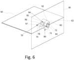
- Fig. 6 illustrates the step of inserting a bonding member 94 through the insertion opening 92 and into the receiving passage 84.
- the bonding member 94 is preferably a (blind) rivet, as these allow for fast mounting, though other suitable bonding members, such as screws, bolt, or click-lock mechanisms, and such may be applied as well.
- the bonding member 82 comprises a rod 96 which is dimensioned to fit into the receiving channel 84. Both ends 95, 97 of the bonding member 94 have a cross-section wider than the receiving channel 84.
- the ends 95, 97 are preferably fixed on the rod 96, so that the ends 95, 97, and thereby the plates 60, 90, are pulled together. Thus a reliable bonding of the plates 60, 90 is achieved.
- the central axis of bonding member 94 is positioned in the plane of the first plate 60, so that the first plate 60 provides rigidity to the bonding.
- the receiving opening 92 is centred at the first edge 62 of the first plate 60, so that the bonding force of the bonding member 94 acts on a neutral line defined by the first edge 62, thereby directing any forces on the bonding member 94 into a neutral line of the first plate 60. This improves the stiffness of the frame. Thereby, the rigidity of the frame is improved.
- Fig. 7 illustrates a second embodiment for bonding two plates 60, 90 together.
- the receiving member 180 has been formed integrally from the first plate 60.
- the receiving channel 184 is formed by a body formed of a plurality of plate strips 183, which have been bent out-of-plane with respect to the first plate 60.
- Each strip 183 is curved out-of-plane and is connected to the first plate 60 via the receiving member holding elements 172.
- the receiving member holding elements 172 are formed as part of the strips 183, but do not substantially contribute to forming the receiving channel 184.
- Each strip 183 is bent in an opposite direction with respect to its neighboring strip 183, so that on one side of the first plate 60 the strips 183 are alternating with empty spaces between.
- the strips 183 extend parallel to the first edge 62, wherein a first strip 183 is preferably positioned at the first edge 62. Opposite of the strips 183 with respect to the first edge 62, a recess 170 is provided at an end of the receiving channel 184.
- the recess 184 is formed by a cut-out opening.
- Fig. 8 illustrates the process for forming the second embodiment in Fig. 8 .
- the first plate 60 is provided with a plurality of openings 170, 173 formed by cutting the first plate 60.
- a plurality of spaced apart cuts 173 parallel to the first edge 62 are cut into the first plate 60 to define the strips 183.
- the cuts 173 may be relatively narrow and allow the strips 183 to be bent out of the plane of the first plate 60 to form the receiving channel 184.
- the strips 183 may be bent using e.g. known embossing techniques. Thereby, the strips 183 are curved into an arch extending between the portions of the strip 183 that form the receiving member holding elements 172. Behind the strips 183 and in line with the receiving channel 184, the recess 170 is cut into the first plate 60. The recess 170 is larger than the cuts 173, at least in its width measured perpendicular to the first edge 62.
- the strips 183 are bent out-of-plane in an alternating manner, so that for every three adjacent strips 183, the middle strip 183 is bent towards the opposite side of the first plate 60 as compared to the outer of the three strips 183.
- the receiving channel 184 is formed of at least three strips 183 bent in this manner. The receiving channel 184 is thus formed with its central axis within the plane of the first plate 60 and extending between the first edge 62 and the recess 170, perpendicular to the first edge 62.
- a second plate 90 may be bonded to the first plate 60 by aligning the receiving opening 92 with the receiving channel 184 and inserting a rivet, such that the plates 60, 90 are bonded together, similar what was described with regard to Fig. 6 .
- Figs. 9 and 10 illustrate a step of a third embodiment of bonding together two metal plates 60, 90.
- the first plate is provided with a receiving member 280 formed as a ring element, though other shapes may be applied as well.
- the receiving member 280 has a central opening, which is preferably formed by a cylindrical channel, cut into it to form the receiving channel 284.
- the body of the receiving member 280 has been integrally formed from the first plate 60 by cutting the recess 270 as well as a further recess at the first edge 62.
- the receiving member 280 is connected on opposite sides to the first plate 60 via the receiving member holding elements 272, formed by relatively narrow bridge elements of the first plate 60.
- the receiving member holding elements 272 along with a portion of the receiving member 280 define a portion of the circumferential edge of the recess 270.
- Fig. 11 illustrates the step of twisting the receiving member holding elements 272, so that the receiving member 280 is rotated or pivoted into an orientation out-of-plane with respect to the first plate 60. While the receiving member holding elements 272 are deformed by the twisting, the receiving member 280 itself remains its shape as in Figs. 9 and 10 , but it is oriented perpendicular to the first plate 60.
- the receiving channel 280 now extends parallel to the plane of the first plate 60.
- the central axis of the receiving channel 284 lies within the plane of the first plate 60.
- the area of the recess 270 is increased with respect to the Fig. 9 by the twisting.
- Fig. 12 illustrates the step of inserting the bonding member 94, similar to Fig. 6 .
- the bonding member 94 is a blind rivet, which is popped into the receiving channel 284 via the insertion opening 92, so that a pulling force is exerted on the plates 60, 90.
- the end 95 of the bonding member 94 in the recess 270 as well as its opposite end 97 at the insertion opening 92 have a greater cross-section than the central portion 96 of the bonding member 94.
- the ends 95, 97 are also wider than respectively the insertion opening 92 and the receiving channel 284, so that the plates 60, 90 are held together by the bonding member 94.
Landscapes
- Accessory Devices And Overall Control Thereof (AREA)
Abstract
A rigid frame for a printer is provided comprising a pair of plates bonded together, wherein a first one of the plates comprises a receiving member formed in a recess (70; 170; 170) adjacent an edge (62) of the first one of plates, the receiving member being connected to the first one of the plates via receiving member holding elements on opposite sides of the receiving member, such that such that a center of the receiving channel is positioned in a plane defined by the first one of the plates and the receiving channel extends substantially perpendicular to the respective edge (62) of the first one of the plates, wherein a second one of the plates is positioned against the respective edge (62) of the first one of the plates at a substantially right angle, such that an insertion opening is aligned with the receiving channel, and wherein a bonding member is inserted via the insertion opening into the receiving channel to hold the two plates together.
Description
- The invention relates to a method for bonding two plates perpendicularly to one another and to a frame formed by such a method.
- Printers comprise a print assembly for forming an image an a print medium. In case of inkjet printing, the print assembly comprises a plurality of printheads for jetting droplets of ink onto the print medium. Therein, the image quality is determined by the accuracy wherein the print medium is positioned with respect to the print assembly. The print assembly and/or a transport device for moving the print medium is generally supported on a frame for the printer. When the rigidity is low, the print medium may not be positioned accurately with respect to the print assembly, reducing the image quality. It is known to form part of a frame by positioning two metal plates perpendicular to one another and bonding these together at a bent portion of one of the plates. The bent portion is generally an edge portion of one of the plates bent at a right angle, wherein one or more openings have been provided. Said openings are aligned with openings in another plate and a bonding member, such as a rivet, is inserted through the openings to hold the plates together. Instabilities in the frame may result in inaccurate positioning of the print medium with respect to the print assembly, which may affect the image quality of the printed image.
- It is an object of the invention improve the rigidity of a printer's frame.
- In accordance with the present invention, a method for bonding two plates perpendicularly to one another according to
claim 1 and a frame according to claim 12 are provided. The method comprises the steps of: - forming a recess in a first one of the plates adjacent an edge of said plate;
- providing a receiving member in the recess, wherein the receiving member comprises a receiving channel, such that a center of the receiving channel is positioned in a plane defined by the first one of the plates and the channel extends substantially perpendicular to the respective edge of the first one of the plates;
- providing an insertion opening in a second one of the plates;
- aligning the plates, such that the insertion opening overlaps with the receiving channel; and
- inserting a bonding member via the insertion opening into the receiving channel, such that the bonding member is secured in the receiving channel, thereby holding the plates together.
- It is the insight of the inventor that by positioning the bonding member within the plane of the first one the plates, the rigidity of the frame is improved. The second one of the plates is positioned perpendicular against the first one of the plates, so that the bonding member extends through the insertion opening into the receiving channel, which is within the plane of the first one of the plates. Bending of the second one of the plates due to the bonding force is reduced or prevented, since the bonding force is exerted on a line which overlaps with the first edge of the first one of the plates. The bonding member engages the second one of the plates, where the second one of the plates is supported by the first edge of the first one of the plates, which prevents or reduces bending of the second one of the plates at the bonding member. Thereby, a rigid frame can be formed from two plates in a relatively simple and low-costs manner. The higher rigidity of the frame when applied in a transport device and/or print assembly for a printer would reduce unintended movement of a print medium with respect to the print assembly, which would result in a more accurate positioning of the image on the print medium. This increases the image quality. Thereby the object of the present invention has been achieved.
- More specific optional features of the invention are indicated in the dependent claims.
- In an embodiment, the recess is delimited by receiving member holding elements for holding the receiving member onto the first one of the plates. The receiving member with the receiving channel is connected to the first plate via the receiving member holding elements. The connection is preferably rigid. One or more receiving member holding elements form or define a portion of the edge of the recess.
- In an embodiment, the receiving member holding elements are formed from the first one of the plates and extend parallel to the respective edge. The receiving member holding elements are integrally formed from the first one of the plates, for example by cutting the respective plate.
- In an embodiment, the receiving member is formed from the first one of the plates. The receiving member is in this embodiment integrally formed with the first one of the plates, for example by cutting the respective plate. Preferably when forming the recess, at least a portion or edge of the receiving member is formed or defined. The receiving member is formed of plate material. The first one of the plates is cut, such that receiving member is formed connected to the first one of the plates via the receiving member holding elements. The receiving member holding elements are preferably formed of plate material as well.
- In an embodiment, the recess is formed by at least partially bending the receiving member out of a plane defined by the first one of the plates. The plate material of the receiving member is bent out of the plane of the first one of the plates to form a three-dimensional structure, wherein a portion of the receiving member extends above and/or below the plane of the first one of the plates. Alternatively, during bending the receiving member may retain its shape, but the receiving member holding elements are deformed. Therein, the receiving member holding elements and/or at least a portion of the receiving member may be deformed, by e.g. bending or twisting, to move the receiving member out of the respective plane.
- In an embodiment, the receiving member holding elements comprise twist elements connected at opposite sides of the receiving member to the first one of the plates, such that the receiving member is rotatable out of the plane around an axis defined by the receiving member holding elements. The receiving member is held to the first plate, such that it can be rotated, wherein the receiving member holding elements become twisted. The twisting deformation of the receiving member holding elements is permanent, such that the receiving member remains in its rotated, final position. In another embodiment, the receiving channel is defined by a central opening of a ring element of the receiving member.
- In an embodiment, the receiving member comprises at least two adjacent strips formed of the first one of the plates, each strip connected on opposite sides to the first one of the plates via the receiving member holding elements, such that the strips may be bent out of the plane in opposite directions to form the receiving channel. The receiving channel is formed by the alternatingly bent strips. Preferably, at least three strips are provided in a row, wherein the strips have similar dimensions. The strips preferably extend parallel to the first edge and are at either end connected to the first one of the plates via a receiving member holding element. The strips are permanently deformed by out-of-plane bending by e.g. debossing. Each strips forms an arch, wherein each strip is in an orientation which is rotated 180° with respect to a neighboring strip.
- In an embodiment, the receiving member comprises a body defining the receiving channel and grooves for receiving the receiving member holding elements for mounting the body onto the first one of the plates. In this embodiment, the receiving member may be formed separate from the first one of the plates. The body has grooves running parallel to the receiving channel on the outside of the body. Each groove has a length less than that of the receiving channel, so that each groove comprises an end wall in the direction of the receiving channel. The receiving member holding elements are formed by protruding sections of the first one of the plates, which are inserted into the grooves as the body is moved through the recess perpendicular to the first edge. When the receiving member holding elements contact the end walls, the body is restricted from moving further in the direction of the second one of the plates. Thus, the plates can be secured together by means of a bonding member.
- In a preferred embodiment, the plates are formed of metal, such as steel.
- In an embodiment, the method further comprises the step of forming a printer frame from the bonded plates and mounting the printer frame in a printer. The printer comprises a transport device for positioning a print medium with respect to a printing assembly, for example an endless belt conveyor. The transport device is mounted on the frame formed of the bonded, so that it is rigidly secured, reducing unintended displacement of the print medium with respect to the print assembly.
- In an embodiment, the receiving member holding elements and at least part of the recess are formed by cutting the first one of the plate. The cutting may be performed by drilling, milling, hydrocutting, laser cutting, punching, or any other suitable cutting technique. The recess is cut into the first one of the plates as an opening. The receiving member holding elements are also formed by removing plate material around them by cutting.
- In an embodiment, the bonding member is a rivet, preferably a blind rivet.
- The present invention further relates to a frame for a printer comprising a pair of plates bonded together, wherein a first one of the plates comprises a receiving member provided in a recess adjacent an edge of the first one of plates, the receiving member being connected to the first one of the plates via receiving member holding elements on opposite sides of the receiving member, such that such that a center of the receiving channel is positioned in a plane defined by the first one of the plates and the receiving channel extends substantially perpendicular to the respective edge of the first one of the plates, wherein a second one of the plates is positioned against the respective edge of the first one of the plates at a substantially right angle, such that an insertion opening is aligned with the receiving channel, and wherein a bonding member is inserted via the insertion opening into the receiving channel to hold the two plates together. The frame with the bonded plates may be formed by any of the above described embodiments. The frame is applied in a printer, preferably to support a transport device for moving print media past a print assembly.
- In an embodiment, the receiving channel extends between the recess and the first edge. The central axis of the receiving channel is positioned between the recess and the first edge within the plane of the first one of the plates. The central axis is perpendicular to the first edge.
- In an embodiment, the recess comprises a free space on an opposite side of the receiving member with respect to the respective edge. The recess forms a free space wherein the bonding member may extend during the mounting of the bonding member. During mounting, a rivet, bolt, screw, etc. requires an open space where it exits the receiving channel for forming the wider end of the holding member, which prevents it from travelling back through the receiving channel. Preferably, the bonding member is a rivet, specifically a blind rivet.
- In an embodiment, the receiving member holding elements define a portion of the edge of the recess. In another embodiment, the receiving member holding elements are formed from the first one of the plates.
- Further scope of applicability of the present invention will become apparent from the detailed description given hereinafter. However, it should be understood that the detailed description and specific examples, while indicating preferred embodiments of the present invention, are given by way of illustration only, since various changes and modifications within the spirit and scope of the present invention will become apparent to those skilled in the art from this detailed description.
- The present invention will become more fully understood from the detailed description given herein below and the accompanying drawings which are given by way of illustration only, and thus are not limitative of the present invention, and wherein:
-
Fig. 1 is a schematic representation of a printer; -
Figs. 2 to 6 illustrate the steps of a first embodiment of a method for bonding together two plates to form a frame for use in the printer inFig. 1 ; -
Fig. 7 illustrates a perspective view of a second embodiment for bonding together two plates to form a frame for use in the printer inFig. 1 ; -
Fig. 8 illustrates a schematic, top-down view of the first plate in the second embodiment inFig. 7 ; -
Fig. 9 illustrates a perspective view of a third second embodiment for bonding together two plates to form a frame for use in the printer inFig. 1 ; and -
Figs. 10 to 12 illustrate the steps of the third embodiment of a method for bonding together two plates to form a frame for use in the printer inFig. 1 . - The present invention will now be described with reference to the accompanying drawings, wherein the same reference numerals have been used to identify the same or similar elements throughout the several views.
-
FIG. 1 shows schematically an embodiment of aprinter 1 according to the present invention. Theprinter 1, for purposes of explanation, is divided into anoutput section 5, a print engine andcontrol section 3, alocal user interface 7 and an input section 4. The individual components therein may be mounted on a common frame or separate frames may be applied per section or component. The frames are preferably formed of a plurality of metal plates, which are bonded together under an angle by means of bonding member, such as a rivet or screw. While a specific printer is shown and described, the disclosed embodiments may be used with other types of printer such as an ink jet print system, an electrographic print system, etc. - The
output section 5 comprises afirst output holder 52 for holding printed image receiving material, for example a plurality of sheets. Theoutput section 5 may comprise asecond output holder 55. While 2 output holders are illustrated inFIG. 1 , the number of output holders may include one, two, three or more output holders. The printed image receiving material is transported from the print engine andcontrol section 3 via aninlet 53 to theoutput section 5. When a stack ejection command is invoked by thecontroller 37 for thefirst output holder 52, first guiding means 54 are activated in order to eject the plurality of sheets in thefirst output holder 52 outwards to a firstexternal output holder 51. When a stack ejection command is invoked by thecontroller 37 for thesecond output holder 55, second guiding means 56 are activated in order to eject the plurality of sheets in thesecond output holder 55 outwards to a secondexternal output holder 57. - The
output section 5 is digitally connected by means of acable 60 to the print engine andcontrol section 3 for bi-directional data signal transfer. - The print engine and
control section 3 comprises a print engine and acontroller 37 for controlling the printing process and scheduling the plurality of sheets in a printing order before they are separated frominput holder - The
controller 37 is a computer, a server or a workstation, connected to the print engine and connected to the digital environment of the printer, for example a network N for transmitting a submitted print job to theprinter 1. InFIG. 1 thecontroller 37 is positioned inside the print engine andcontrol section 3, but thecontroller 37 may also be at least partially positioned outside the print engine andcontrol section 3 in connection with the network N in a workstation N1. - The
controller 37 comprises a printjob receiving section 371 permitting a user to submit a print job to theprinter 1, the print job comprising image data to be printed and a plurality of print job settings. Thecontroller 37 comprises a printjob queue section 372 comprising a print job queue for print jobs submitted to theprinter 1 and scheduled to be printed. Thecontroller 37 comprises asheet scheduling section 373 for determining for each of the plurality of sheets of the print jobs in the print job queue an entrance time in the paper path of the print engine andcontrol section 3, especially an entrance time for the first pass and an entrance time for the second pass in the loop in the paper path according to the present invention. Thesheet scheduling section 373 will also be calledscheduler 373 hereinafter. - The
sheet scheduling section 373 takes the length of the loop into account. The length of the loop corresponds to a loop time duration of a sheet going through the loop dependent on the velocity of the sheets in the loop. The loop time duration may vary per kind of sheet, i.e. a sheet with different media properties. - Resources may be recording material located in the input section 4, marking material located in a
reservoir 39 near or in the print head orprint assembly 31 of the print engine, or finishing material located near the print head orprint assembly 31 of the print engine or located in the output section 5 (not shown). - The paper path comprises a plurality of
paper path sections entry point 36 of the print engine andcontrol section 3 along the print head orprint assembly 31 to theinlet 53 of theoutput section 5. Thepaper path sections - The print head or
print assembly 31 is suitable for ejecting and/or fixing marking material to image receiving material. The print head orprint assembly 31 is positioned near thepaper path section 34. The print head orprint assembly 31 may be an inkjet print head, a direct imaging toner assembly or an indirect imaging toner assembly. - While an image receiving material is transported along the
paper path section 34 in a first pass in the loop, the image receiving material receives the marking material through the print head orprint assembly 31. A nextpaper path section 32 is aflip unit 32 for selecting a different subsequent paper path for simplex or duplex printing of the image receiving material. Theflip unit 32 may be also used to flip a sheet of image receiving material after printing in simplex mode before the sheet leaves the print engine andcontrol section 3 via acurved section 38 of theflip unit 32 and via theinlet 53 to theoutput section 5. Thecurved section 38 of theflip unit 32 may not be present and the turning of a simplex page has to be done via anotherpaper path section 35. - In case of duplex printing on a sheet or when the
curved section 38 is not present, the sheet is transported along the loop viapaper path section 35A in order to turn the sheet for enabling printing on the other side of the sheet. The sheet is transported along thepaper path section 35 until it reaches amerging point 34A at which sheets entering thepaper path section 34 from theentry point 36 interweave with the sheets coming from thepaper path section 35. The sheets entering thepaper path section 34 from theentry point 36 are starting their first pass along the print head orprint assembly 31 in the loop. The sheets coming from thepaper path section 35 are starting their second pass along the print head orprint assembly 31 in the loop. When a sheet has passed the print head orprint assembly 31 for the second time in the second pass, the sheet is transported to theinlet 53 of theoutput section 5. - The input section 4 may comprise at least one
input holder control section 3. Sheets of image receiving material are separated from theinput holders input holders means outlet 36 for entrance in the print engine andcontrol section 3. Eachinput holder FIG. 1 , the number of input holders may include one, two, three or more input holders. - The
local user interface 7 is suitable for displaying user interface windows for controlling the print job queue residing in thecontroller 37. In another embodiment a computer N1 in the network N has a user interface for displaying and controlling the print job queue of theprinter 1. - The
printer 1 comprises at least one frame for mounting at least one of the above mentioned components. To form the frame, afirst plate 60 is provided inFig. 2 . Thefirst plate 60 is a flat, substantiallyrectangular plate 60, preferably formed of metal, such as steel. Thefirst plate 60 has afirst edge 62 which is to be mounted against a second plate (90 inFig. 5 ). -
Fig. 3 illustrates the step of forming arecess 70 in thefirst plate 60 adjacent thefirst edge 62. Therecess 70 is formed by cutting an opening in thefirst plate 60 near thefirst edge 62. The cutting may be formed by any suitable cutting technique, such as punching, drilling, hydrocutting, laser cutting, etc. Therecess 70 has been cut, so that a pair of opposing receivingmember holding elements 72 are formed along thefirst edge 62. The receivingmember holding elements 72 protrude parallel to thefirst edge 62 towards one another to form between them anarrow gap portion 76, which has a width smaller than an average or maximum width of therecess 70, measured parallel to thefirst edge 62. Thegap portion 76 and therecess 70 together form a single opening, which has a narrow front opening, formed by thegap portion 76, in thefirst edge 62 with a larger rear opening behind thegap portion 76. -
Fig. 4 illustrates the step of providing a receivingmember 80 in therecess 70. The receivingmember 80 has a preferably cylindrical body 82 (though other suitable shapes may be applied as well), which comprises a receivingchannel 84. Thebody 82 is provided with grooves on opposite sides, wherein the receivingmember holding elements 72 are inserted. The grooves extend perpendicular to thefirst edge 62 and parallel to the receivingchannel 84. The grooves extend only partially along thebody 82, such that each groove comprises a stopping segment, which restricts movement of thebody 82 with respect to thefirst edge 62. Thebody 82 is first inserted into therecess 70. The grooves are then aligned with the receivingmember holding elements 72 and then thebody 82 is moved perpendicular to thefirst edge 62, so that the receivingmember holding elements 72 slide in the grooves. When the receivingmember holding elements 72 contact the stopping elements formed by the end walls of each groove, thebody 82 is in its end position and is prevented from moving further in the respective direction away from therecess 70. Thereby, the receivingchannel 84 has been positioned, so its central axis lies in the plane of thefirst plate 60. The receivingchannel 84 may extend above and below thefirst plate 62, but preferably in a mirror-symmetric manner with respect to thefirst plate 62. The receivingchannel 84 further extends perpendicular to thefirst edge 62 and overlaps with thegap portion 76, so that the receivingchannel 84 is free of any plate material. The central axis of the receivingchannel 84 is positioned, at least partially, between therecess 70 and thefirst edge 62. -
Fig. 5 illustrates the step of providing asecond plate 90 against thefirst plate 60. Thesecond plate 90 comprises aninsertion opening 92 in the form of a through-hole, which preferably has a cross-section similar to that of the receivingchannel 84. Thesecond plate 90 is positioned at a right angle against thefirst plate 60, so that the twoplates plates insertion opening 92 is aligned with respect to the receivingchannel 84, so that these form a passage perpendicular to thefirst edge 62. -
Fig. 6 illustrates the step of inserting abonding member 94 through theinsertion opening 92 and into the receivingpassage 84. The bondingmember 94 is preferably a (blind) rivet, as these allow for fast mounting, though other suitable bonding members, such as screws, bolt, or click-lock mechanisms, and such may be applied as well. The bondingmember 82 comprises arod 96 which is dimensioned to fit into the receivingchannel 84. Both ends 95, 97 of thebonding member 94 have a cross-section wider than the receivingchannel 84. The ends 95, 97 are preferably fixed on therod 96, so that the ends 95, 97, and thereby theplates plates member 94 is positioned in the plane of thefirst plate 60, so that thefirst plate 60 provides rigidity to the bonding. The receivingopening 92 is centred at thefirst edge 62 of thefirst plate 60, so that the bonding force of thebonding member 94 acts on a neutral line defined by thefirst edge 62, thereby directing any forces on thebonding member 94 into a neutral line of thefirst plate 60. This improves the stiffness of the frame. Thereby, the rigidity of the frame is improved. -
Fig. 7 illustrates a second embodiment for bonding twoplates Fig. 7 , the receivingmember 180 has been formed integrally from thefirst plate 60. The receivingchannel 184 is formed by a body formed of a plurality of plate strips 183, which have been bent out-of-plane with respect to thefirst plate 60. Eachstrip 183 is curved out-of-plane and is connected to thefirst plate 60 via the receivingmember holding elements 172. The receivingmember holding elements 172 are formed as part of thestrips 183, but do not substantially contribute to forming the receivingchannel 184. Eachstrip 183 is bent in an opposite direction with respect to its neighboringstrip 183, so that on one side of thefirst plate 60 thestrips 183 are alternating with empty spaces between. Thestrips 183 extend parallel to thefirst edge 62, wherein afirst strip 183 is preferably positioned at thefirst edge 62. Opposite of thestrips 183 with respect to thefirst edge 62, arecess 170 is provided at an end of the receivingchannel 184. Therecess 184 is formed by a cut-out opening. -
Fig. 8 illustrates the process for forming the second embodiment inFig. 8 . Thefirst plate 60 is provided with a plurality ofopenings first plate 60. A plurality of spaced apart cuts 173 parallel to thefirst edge 62 are cut into thefirst plate 60 to define thestrips 183. Thecuts 173 may be relatively narrow and allow thestrips 183 to be bent out of the plane of thefirst plate 60 to form the receivingchannel 184. - The
strips 183 may be bent using e.g. known embossing techniques. Thereby, thestrips 183 are curved into an arch extending between the portions of thestrip 183 that form the receivingmember holding elements 172. Behind thestrips 183 and in line with the receivingchannel 184, therecess 170 is cut into thefirst plate 60. Therecess 170 is larger than thecuts 173, at least in its width measured perpendicular to thefirst edge 62. Thestrips 183 are bent out-of-plane in an alternating manner, so that for every threeadjacent strips 183, themiddle strip 183 is bent towards the opposite side of thefirst plate 60 as compared to the outer of the threestrips 183. The receivingchannel 184 is formed of at least threestrips 183 bent in this manner. The receivingchannel 184 is thus formed with its central axis within the plane of thefirst plate 60 and extending between thefirst edge 62 and therecess 170, perpendicular to thefirst edge 62. - A
second plate 90 may be bonded to thefirst plate 60 by aligning the receivingopening 92 with the receivingchannel 184 and inserting a rivet, such that theplates Fig. 6 . -
Figs. 9 and 10 illustrate a step of a third embodiment of bonding together twometal plates Figs. 9 and 10 , the first plate is provided with a receivingmember 280 formed as a ring element, though other shapes may be applied as well. The receivingmember 280 has a central opening, which is preferably formed by a cylindrical channel, cut into it to form the receivingchannel 284. The body of the receivingmember 280 has been integrally formed from thefirst plate 60 by cutting therecess 270 as well as a further recess at thefirst edge 62. The receivingmember 280 is connected on opposite sides to thefirst plate 60 via the receivingmember holding elements 272, formed by relatively narrow bridge elements of thefirst plate 60. The receivingmember holding elements 272 along with a portion of the receivingmember 280 define a portion of the circumferential edge of therecess 270. -
Fig. 11 illustrates the step of twisting the receivingmember holding elements 272, so that the receivingmember 280 is rotated or pivoted into an orientation out-of-plane with respect to thefirst plate 60. While the receivingmember holding elements 272 are deformed by the twisting, the receivingmember 280 itself remains its shape as inFigs. 9 and 10 , but it is oriented perpendicular to thefirst plate 60. The receivingchannel 280 now extends parallel to the plane of thefirst plate 60. Preferably the central axis of the receivingchannel 284 lies within the plane of thefirst plate 60. In the top-down view inFig. 11 , the area of therecess 270 is increased with respect to theFig. 9 by the twisting. -
Fig. 12 illustrates the step of inserting thebonding member 94, similar toFig. 6 . The bondingmember 94 is a blind rivet, which is popped into the receivingchannel 284 via theinsertion opening 92, so that a pulling force is exerted on theplates end 95 of thebonding member 94 in therecess 270 as well as itsopposite end 97 at theinsertion opening 92 have a greater cross-section than thecentral portion 96 of thebonding member 94. The ends 95, 97 are also wider than respectively theinsertion opening 92 and the receivingchannel 284, so that theplates member 94. - Although specific embodiments of the invention are illustrated and described herein, it will be appreciated by those of ordinary skill in the art that a variety of alternate and/or equivalent implementations exist. It should be appreciated that the exemplary embodiment or exemplary embodiments are examples only and are not intended to limit the scope, applicability, or configuration in any way. Rather, the foregoing summary and detailed description will provide those skilled in the art with a convenient road map for implementing at least one exemplary embodiment, it being understood that various changes may be made in the function and arrangement of elements described in an exemplary embodiment without departing from the scope as set forth in the appended claims and their legal equivalents. Generally, this application is intended to cover any adaptations or variations of the specific embodiments discussed herein.
- It will also be appreciated that in this document the terms "comprise", "comprising", "include", "including", "contain", "containing", "have", "having", and any variations thereof, are intended to be understood in an inclusive (i.e. non-exclusive) sense, such that the process, method, device, apparatus or system described herein is not limited to those features or parts or elements or steps recited but may include other elements, features, parts or steps not expressly listed or inherent to such process, method, article, or apparatus. Furthermore, the terms "a" and "an" used herein are intended to be understood as meaning one or more unless explicitly stated otherwise. Moreover, the terms "first", "second", "third", etc. are used merely as labels, and are not intended to impose numerical requirements on or to establish a certain ranking of importance of their objects.
- The present invention being thus described, it will be obvious that the same may be varied in many ways. Such variations are not to be regarded as a departure from the spirit and scope of the present invention, and all such modifications as would be obvious to one skilled in the art are intended to be included within the scope of the following claims.
Claims (15)
- A method for bonding two plates (60, 90) perpendicularly to one another, comprising the steps of:- forming a recess (70; 170; 170) in a first one of the plates (60, 90) (60, 90) adjacent an edge (62) of said plate (60);- providing a receiving member (80; 180; 280) in the recess (70; 170; 170), wherein the receiving member (80; 180; 280) comprises a receiving channel (84; 184; 284), such that a center of the receiving channel (84; 184; 284) is positioned in a plane defined by the first one of the plates (60, 90) and the receiving channel (84; 184; 284) extends substantially perpendicular to the respective edge (62) of the first one of the plates (60, 90);- providing an insertion opening (90) in a second one of the plates (60, 90);- aligning the plates (60, 90), such that the insertion opening (90) overlaps with the receiving channel (84; 184; 284); and- inserting a bonding member (94) via the insertion opening (90) into the receiving channel (84; 184; 284), such that the bonding member (94) is secured in the receiving channel (84; 184; 284), thereby holding the plates (60, 90) together.
- The method according to claim 1, wherein the recess (70; 170; 170) is delimited by receiving member holding elements (72; 172; 272) for holding the receiving member onto the first one of the plates (60, 90).
- The method according to claim 2, wherein the receiving member holding elements (72; 172; 272) are formed from the first one of the plates (60, 90) and extend parallel to the respective edge (62).
- The method according to any of the previous claims, wherein the receiving member (80; 180; 280) is formed from the first one of the plates (60, 90).
- The method according to claim 4, wherein the recess (70; 170; 170) is formed by at least partially bending the receiving member (80; 180; 280) out of a plane defined by the first one of the plates (60, 90).
- The method according to claim 5, wherein the receiving member holding elements (72; 172; 272) comprise twist elements connected at opposite sides of the receiving member (80; 180; 280) to the first one of the plates (60, 90), such that the receiving member (80; 180; 280) is rotatable out of the plane around an axis defined by the receiving member holding elements (72; 172; 272), and preferably wherein the receiving channel (84; 184; 284) is defined by a central opening of the ring element.
- The method according to claim 5, wherein the receiving member (80; 180; 280) comprises at least two adjacent strips (183) formed of the first one of the plates (60, 90), each strip (183) being connected on opposite sides to the first one of the plates (60, 90) via the receiving member holding elements (72; 172; 272), such that the strips (183) may be bent out of the plane in opposite directions to form the receiving channel (84; 184; 284).
- The method according to any of the claims 1 to 3, wherein the receiving member (80; 180; 280) comprises a body defining the receiving channel (84; 184; 284) and grooves for receiving the receiving member holding elements (72; 172; 272) for mounting the body onto the first one of the plates (60, 90).
- The method according to any of the previous claims, wherein the plates (60, 90) are formed of metal.
- The method according to any of the previous claims, further comprising the step of forming a printer frame from the bonded plates (60, 90) and mounting the printer frame in a printer.
- The method according to any of the previous claims, wherein the receiving member holding elements (72; 172; 272) and at least part of the recess (70; 170; 170) are formed by cutting the first one of the plate.
- A frame for a printer comprising a pair of plates (60, 90) bonded together, wherein a first one of the plates (60, 90) comprises a receiving member (80; 180; 280) provided in a recess (70; 170; 170) adjacent an edge (62) of the first one of plates (60, 90), the receiving member (80; 180; 280) being connected to the first one of the plates (60, 90) via receiving member holding elements (72; 172; 272) on opposite sides of the receiving member (80; 180; 280), such that such that a center of the receiving channel (84; 184; 284) is positioned in a plane defined by the first one of the plates (60, 90) and the receiving channel (84; 184; 284) extends substantially perpendicular to the respective edge (62) of the first one of the plates (60, 90), wherein a second one of the plates (60, 90) is positioned against the respective edge (62) of the first one of the plates (60, 90) at a substantially right angle, such that an insertion opening (90) is aligned with the receiving channel (84; 184; 284), and wherein a bonding member (94) is inserted via the insertion opening (90) into the receiving channel (84; 184; 284) to hold the two plates (60, 90) together.
- The frame according to claim 12, wherein recess (70; 170; 170) comprises a free space on an opposite side of the receiving member with respect to the respective edge (62), preferably wherein the receiving member holding elements (72; 172; 272) define a portion of the edge (62) of the recess (70; 170; 170).
- The frame according to claim 12 or 13, wherein the receiving member holding elements (72; 172; 272) are formed from the first one of the plates (60, 90).
- The frame according to any of the claims 12 to 14, wherein the receiving channel (84; 184; 284) (84; 184; 284) extends between the recess (70; 170; 270) and the first edge (62).
Priority Applications (1)
| Application Number | Priority Date | Filing Date | Title |
|---|---|---|---|
| EP23176508.2A EP4470789A1 (en) | 2023-05-31 | 2023-05-31 | Method of rigidly bonding together two plates for forming a frame for a printer |
Applications Claiming Priority (1)
| Application Number | Priority Date | Filing Date | Title |
|---|---|---|---|
| EP23176508.2A EP4470789A1 (en) | 2023-05-31 | 2023-05-31 | Method of rigidly bonding together two plates for forming a frame for a printer |
Publications (1)
| Publication Number | Publication Date |
|---|---|
| EP4470789A1 true EP4470789A1 (en) | 2024-12-04 |
Family
ID=86646491
Family Applications (1)
| Application Number | Title | Priority Date | Filing Date |
|---|---|---|---|
| EP23176508.2A Pending EP4470789A1 (en) | 2023-05-31 | 2023-05-31 | Method of rigidly bonding together two plates for forming a frame for a printer |
Country Status (1)
| Country | Link |
|---|---|
| EP (1) | EP4470789A1 (en) |
Citations (3)
| Publication number | Priority date | Publication date | Assignee | Title |
|---|---|---|---|---|
| US5451102A (en) * | 1994-01-13 | 1995-09-19 | Chuan; Yuan-Jung | Cabinet with connecting mechanism for two adjacent wall plate |
| WO2012095454A1 (en) * | 2011-01-14 | 2012-07-19 | Sean Phillips | Connector assembly for an article of furniture |
| JP2016124237A (en) * | 2015-01-06 | 2016-07-11 | キヤノン株式会社 | Structure of image forming apparatus and manufacturing method for the same |
-
2023
- 2023-05-31 EP EP23176508.2A patent/EP4470789A1/en active Pending
Patent Citations (3)
| Publication number | Priority date | Publication date | Assignee | Title |
|---|---|---|---|---|
| US5451102A (en) * | 1994-01-13 | 1995-09-19 | Chuan; Yuan-Jung | Cabinet with connecting mechanism for two adjacent wall plate |
| WO2012095454A1 (en) * | 2011-01-14 | 2012-07-19 | Sean Phillips | Connector assembly for an article of furniture |
| JP2016124237A (en) * | 2015-01-06 | 2016-07-11 | キヤノン株式会社 | Structure of image forming apparatus and manufacturing method for the same |
Similar Documents
| Publication | Publication Date | Title |
|---|---|---|
| JP5139382B2 (en) | Buffering system and method for handling marking engine behavior uncertainty | |
| JP4229022B2 (en) | Conveyance control device, conveyance system, and image forming system | |
| US12344018B2 (en) | Registration of duplex printed sheets in a sheet stacking device | |
| US8500236B2 (en) | Computer based method and system for adjusting page placement on a continuous feed print engine | |
| EP4242149B1 (en) | An inkjet sheet printer with a sheet stacker comprising a sheet flipping device | |
| EP4043376B1 (en) | Sheet stacking apparatus, printing apparatus, control method, and corresponding computer program | |
| US12043023B2 (en) | Sheet conveyor for a printer comprising pressing means for flattening a sheet | |
| JP2015016637A (en) | Printing device | |
| JP6203836B2 (en) | How to fasten sheet bundles in the post-processing unit | |
| US20230242366A1 (en) | Sheet stacker for thin or weak print media | |
| EP3636568B1 (en) | Sheet transport apparatus for an inkjet sheet printer | |
| EP4036039B1 (en) | Liftable transport pinch for a sheet printer | |
| NL2028040B1 (en) | A sheet conveyor for a printer comprising a fastener for securing a roller onto a frame of the conveyor | |
| US20180211142A1 (en) | Printing system for cut sheets on a plurality of media types and a method therefor | |
| JP6385111B2 (en) | Processing apparatus, method thereof, and program | |
| US20090232576A1 (en) | Printer | |
| US11945211B2 (en) | Printing with media roll changes and nonproduction frames | |
| US6511737B1 (en) | Printable sheet of material | |
| JP2026083776A (en) | Stiffness measuring device | |
| US9740968B2 (en) | Method and device for automatic insertion of proof sheets in running printing applications in digital printing systems | |
| EP2250027A1 (en) | Sheet feed assembly defining curved and straight feed path | |
| EP3104228A1 (en) | Method for scheduling a reload of supply material in a printing system | |
| JP2005008394A (en) | Paper delivery guide for multiprinter | |
| JPH05139600A (en) | Paper ejection mechanism | |
| JP2018079649A (en) | Printer |
Legal Events
| Date | Code | Title | Description |
|---|---|---|---|
| PUAI | Public reference made under article 153(3) epc to a published international application that has entered the european phase |
Free format text: ORIGINAL CODE: 0009012 |
|
| STAA | Information on the status of an ep patent application or granted ep patent |
Free format text: STATUS: THE APPLICATION HAS BEEN PUBLISHED |
|
| AK | Designated contracting states |
Kind code of ref document: A1 Designated state(s): AL AT BE BG CH CY CZ DE DK EE ES FI FR GB GR HR HU IE IS IT LI LT LU LV MC ME MK MT NL NO PL PT RO RS SE SI SK SM TR |
|
| STAA | Information on the status of an ep patent application or granted ep patent |
Free format text: STATUS: REQUEST FOR EXAMINATION WAS MADE |
|
| 17P | Request for examination filed |
Effective date: 20250604 |
|
| STAA | Information on the status of an ep patent application or granted ep patent |
Free format text: STATUS: EXAMINATION IS IN PROGRESS |