EP4470788A1 - Printer and cutter unit of printer - Google Patents
Printer and cutter unit of printer Download PDFInfo
- Publication number
- EP4470788A1 EP4470788A1 EP22924013.0A EP22924013A EP4470788A1 EP 4470788 A1 EP4470788 A1 EP 4470788A1 EP 22924013 A EP22924013 A EP 22924013A EP 4470788 A1 EP4470788 A1 EP 4470788A1
- Authority
- EP
- European Patent Office
- Prior art keywords
- cutter unit
- printer
- print medium
- cutter
- cover
- Prior art date
- Legal status (The legal status is an assumption and is not a legal conclusion. Google has not performed a legal analysis and makes no representation as to the accuracy of the status listed.)
- Pending
Links
Images




Classifications
-
- B—PERFORMING OPERATIONS; TRANSPORTING
- B41—PRINTING; LINING MACHINES; TYPEWRITERS; STAMPS
- B41J—TYPEWRITERS; SELECTIVE PRINTING MECHANISMS, i.e. MECHANISMS PRINTING OTHERWISE THAN FROM A FORME; CORRECTION OF TYPOGRAPHICAL ERRORS
- B41J11/00—Devices or arrangements of selective printing mechanisms, e.g. ink-jet printers or thermal printers, for supporting or handling copy material in sheet or web form
- B41J11/66—Applications of cutting devices
- B41J11/70—Applications of cutting devices cutting perpendicular to the direction of paper feed
-
- B—PERFORMING OPERATIONS; TRANSPORTING
- B26—HAND CUTTING TOOLS; CUTTING; SEVERING
- B26D—CUTTING; DETAILS COMMON TO MACHINES FOR PERFORATING, PUNCHING, CUTTING-OUT, STAMPING-OUT OR SEVERING
- B26D1/00—Cutting through work characterised by the nature or movement of the cutting member or particular materials not otherwise provided for; Apparatus or machines therefor; Cutting members therefor
- B26D1/01—Cutting through work characterised by the nature or movement of the cutting member or particular materials not otherwise provided for; Apparatus or machines therefor; Cutting members therefor involving a cutting member which does not travel with the work
- B26D1/04—Cutting through work characterised by the nature or movement of the cutting member or particular materials not otherwise provided for; Apparatus or machines therefor; Cutting members therefor involving a cutting member which does not travel with the work having a linearly-movable cutting member
- B26D1/06—Cutting through work characterised by the nature or movement of the cutting member or particular materials not otherwise provided for; Apparatus or machines therefor; Cutting members therefor involving a cutting member which does not travel with the work having a linearly-movable cutting member wherein the cutting member reciprocates
- B26D1/08—Cutting through work characterised by the nature or movement of the cutting member or particular materials not otherwise provided for; Apparatus or machines therefor; Cutting members therefor involving a cutting member which does not travel with the work having a linearly-movable cutting member wherein the cutting member reciprocates of the guillotine type
- B26D1/085—Cutting through work characterised by the nature or movement of the cutting member or particular materials not otherwise provided for; Apparatus or machines therefor; Cutting members therefor involving a cutting member which does not travel with the work having a linearly-movable cutting member wherein the cutting member reciprocates of the guillotine type for thin material, e.g. for sheets, strips or the like
-
- B—PERFORMING OPERATIONS; TRANSPORTING
- B41—PRINTING; LINING MACHINES; TYPEWRITERS; STAMPS
- B41J—TYPEWRITERS; SELECTIVE PRINTING MECHANISMS, i.e. MECHANISMS PRINTING OTHERWISE THAN FROM A FORME; CORRECTION OF TYPOGRAPHICAL ERRORS
- B41J29/00—Details of, or accessories for, typewriters or selective printing mechanisms not otherwise provided for
- B41J29/12—Guards, shields or dust excluders
- B41J29/13—Cases or covers
-
- B—PERFORMING OPERATIONS; TRANSPORTING
- B41—PRINTING; LINING MACHINES; TYPEWRITERS; STAMPS
- B41J—TYPEWRITERS; SELECTIVE PRINTING MECHANISMS, i.e. MECHANISMS PRINTING OTHERWISE THAN FROM A FORME; CORRECTION OF TYPOGRAPHICAL ERRORS
- B41J3/00—Typewriters or selective printing or marking mechanisms characterised by the purpose for which they are constructed
- B41J3/407—Typewriters or selective printing or marking mechanisms characterised by the purpose for which they are constructed for marking on special material
- B41J3/4075—Tape printers; Label printers
Definitions
- the present invention relates to a printer and a cutter unit of the printer.
- JP2006-335016A discloses a printer including a printer body having a printing unit that prints data on a label (a print medium), a cutter unit (a cutter unit body) having a cutter (a cutter blade) that is provided in the printer body and cuts the label in a direction orthogonal to a feed direction, and a cover (a cutter unit cover) that is attached to the printer body so as to cover an outer surface of the cutter unit and has a paper discharge port (a discharge port) for discharging the label on which the data is printed.
- Some labels are provided with an adhesive for sticking to an adherend.
- the adhesive may adhere to the cutter blade. For this reason, in order to remove the adhesive adhering to the cutter blade, it is necessary to periodically clean the cutter blade.
- the present inventor has proposed that the cutter unit body and the cutter unit cover are integrated into one unit.
- the present invention has been made in view of the above problems, and an object of the present invention is to integrate a cutter unit body and a cutter unit cover into one unit and facilitate cleaning of a cutter blade.
- a printer includes a cutter unit attachable to and detachable from a printer body, wherein the cutter unit includes a cutter unit body configured to hold a cutter blade that cuts a print medium, and a cutter unit cover having a discharge port configured to allow the print medium to be discharged therethrough, and pivotally supported by an opening and closing shaft so as to be openable and closable with respect to the cutter unit body.
- the cutter unit includes the cutter unit body that holds the cutter blade and the cutter unit cover having the discharge port configured to allow the print medium to be discharged therethrough, and the cutter unit cover is pivotally supported by the opening and closing shaft so as to be openable and closable with respect to the cutter unit body. For this reason, when the cutter unit cover is in an open state, a surface of the cutter blade facing the cutter unit cover can be easily cleaned. Therefore, the cutter unit body and the cutter unit cover can be integrated into one unit, and the cutter blade can be easily cleaned.
- FIGS. 1 to 10 a printer 1 according to an embodiment of the present invention will be described with reference to FIGS. 1 to 10 .
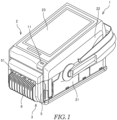
- FIG. 1 is a perspective view of the printer 1.
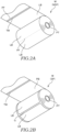
- FIG. 2A is a perspective view of an example of a linerless print medium M of the printer 1.
- FIG. 2B is a perspective view of an example of the print medium M used for continuous issue and peel-off issue of the printer 1.
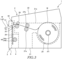
- FIG. 3 is a schematic configuration diagram showing a configuration of a main part of the printer 1.
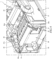
- FIG. 4 is a perspective view showing a state in which a cutter unit 3 is detached from the printer 1.
- FIG. 5 is a front perspective view of the cutter unit 3.
- FIG. 6 is a rear perspective view of the cutter unit 3.
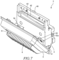
- FIG. 7 is a front perspective view showing a state in which the cutter unit 3 shown in FIG. 5 is opened.
- FIG. 8 is a perspective view showing a state in which a protective cover 6 is detached from the printer 1.
- the printer 1 includes a printer body 2 and the cutter unit 3.
- the printer 1 is a direct thermal printer that performs printing by heating the print medium M (see FIGS. 2A and 2B ) that is thermal paper coated with a thermosensitive color developing agent that develops color when a predetermined temperature range is reached.
- a direction along a longitudinal direction (a feed direction) of the print medium M to be fed is also referred to as a "front-rear direction”
- a direction along a width direction of the print medium M is also referred to as a "left-right direction”
- a direction along a thickness direction of the print medium M to be fed is also referred to as an "up-down direction”.
- the print medium M is held by a paper tube PT in a state of being wound in a roll shape.
- the print medium M is a continuous linerless label NSP.
- a continuous label SP having a liner sheet PB may be used as the print medium M.
- a print surface (a front surface) of long thermal paper wound in a roll shape is coated with a release agent such as silicone, and a surface (a back surface) opposite to the print surface is coated with an adhesive for sticking to an adherend.
- perforations PF may be formed at predetermined intervals. In this case, each region partitioned by the perforations PF constitutes one label LB.
- a black strip-shaped timing mark TM used for detecting a position of the label LB is formed on the back surface of the thermal paper.
- the continuous label SP includes the long liner sheet PB wound in a roll shape and a plurality of labels LB temporarily attached to a front surface of the liner sheet PB at predetermined intervals.
- the label LB temporarily attached to the front surface of the liner sheet PB is a thermal label in which a print surface (a front surface) is coated with a thermosensitive color developing agent and a surface (a back surface) opposite to the print surface is coated with an adhesive.
- a gap G of about 3 millimeters which is a region where the liner sheet PB is exposed, is provided between a pair of adjacent labels LB.
- the black strip-shaped timing mark TM used for detecting a position of the label LB is formed on a back surface of the liner sheet PB.
- the front surface of the liner sheet PB is coated with a release agent such as silicone to facilitate the peeling of the label LB.
- the printer body 2 includes a housing 21, a printer cover 22, a touch panel display 23, an accommodation portion 24, a platen roller 25 serving as a feed roller, a thermal head 26, a first auxiliary roller 27a, a second auxiliary roller 27b, a guide member 28, and a cutter unit attachment portion 29.
- the housing 21 constitutes an outer shape of the printer body 2.
- the housing 21 is provided with the accommodation portion 24, the first auxiliary roller 27a, the platen roller 25, the guide member 28, and the cutter unit attachment portion 29.
- the housing 21 is provided with a lock mechanism (not shown) for maintaining the printer cover 22 in a closed state. The lock mechanism is released by operating a lever 11 (see FIG. 1 ) provided on the printer cover 22.
- the printer cover 22 covers a part of the housing 21.
- the printer cover 22 is provided with the touch panel display 23, the thermal head 26, and the second auxiliary roller 27b.
- the printer cover 22 is swingably supported at one end by a support shaft (not shown) provided on the housing 21.
- the printer cover 22 can be switched between an open state (refer to FIG. 4 ) in which each component accommodated in an opening 21a formed in a part of the housing 21 is opened and a closed state (refer to FIG. 1 ) in which each component is closed by swinging about the support shaft as a fulcrum.
- the touch panel display 23 is provided on an outer surface of the printer cover 22.
- the touch panel display 23 is disposed on an upper surface of the printer cover 22 in the closed state.
- the touch panel display 23 is configured to display predetermined information.
- the predetermined information includes information on the printer 1 and an operation key image.
- a processor of the printer 1 receives an instruction corresponding to the operation key image.
- the touch panel display 23 is, for example, a liquid crystal display having a touch sensor.
- the accommodation portion 24 is located on the support shaft side of the housing 21.
- the accommodation portion 24 is configured to accommodate the print medium M.
- the printer cover 22 When the printer cover 22 is in the open state, the accommodation portion 24 can be accessed from an outside of the printer 1 through the opening 21a. Accordingly, the user can set the print medium M in the accommodation portion 24.
- the platen roller 25 is disposed on a surface (an upper surface) of the housing 21 facing the printer cover 22, and is exposed at the opening 21a.
- the platen roller 25 is located downstream of the first auxiliary roller 27a in the feed direction of the print medium M.
- the platen roller 25 is pivotally supported by the housing 21. That is, the platen roller 25 is rotatable with respect to the housing 21.
- the platen roller 25 is connected to a stepping motor (not shown). The platen roller 25 feeds the print medium M by rotating with respect to the housing 21 under the control of the stepping motor.
- the thermal head 26 is disposed on a surface (a lower surface) of the printer cover 22 facing the housing 21.
- the thermal head 26 is located downstream of the second auxiliary roller 27b in the feed direction of the print medium M.
- the thermal head 26 includes a plurality of heating elements (not shown) that generate Joule heat when energized.
- the thermal head 26 is connected to a control circuit (not shown). Each heating element generates heat under the control of the control circuit.
- the thermal head 26 constitutes a printing unit that performs printing on the print medium M together with the platen roller 25 provided on the housing 21 side.
- the thermal head 26 is separated from the platen roller 25 when the printer cover 22 is in the open state.
- the thermal head 26 faces the platen roller 25 when the printer cover 22 is in the closed state.
- the print medium M printed by the thermal head 26 is fed to the cutter unit 3 by the rotation of the platen roller 25.
- the first auxiliary roller 27a is disposed on the surface (the upper surface) of the housing 21 facing the printer cover 22, and is exposed at the opening 21a.
- the first auxiliary roller 27a is located downstream of the accommodation portion 24 in the feed direction of the print medium M.
- the first auxiliary roller 27a is pivotally supported by the housing 21. That is, the first auxiliary roller 27a is rotatable with respect to the housing 21.
- the second auxiliary roller 27b is disposed on the surface (the lower surface) of the printer cover 22 facing the housing 21.
- the second auxiliary roller 27b is located downstream of the accommodation portion 24 in the feed direction of the print medium M.
- the second auxiliary roller 27b is pivotally supported by the printer cover 22. That is, the second auxiliary roller 27b is rotatable with respect to the printer cover 22.
- the second auxiliary roller 27b is separated from the first auxiliary roller 27a when the printer cover 22 is in the open state.
- the second auxiliary roller 27b faces the first auxiliary roller 27a and rotates while nipping the print medium M when the printer cover 22 is in the closed state.
- the first auxiliary roller 27a and the second auxiliary roller 27b assist in feeding the print medium M from the accommodation portion 24 to the platen roller 25.
- the guide member 28 is provided in a feed path of the print medium M including the first auxiliary roller 27a and the platen roller 25, and is exposed at the opening 21a.
- the guide member 28 is a substantially flat plate-shaped resin member that guides the print medium M to be fed by the first auxiliary roller 27a and the platen roller 25.
- the guide member 28 includes a pair of protruding ends 28a.
- the pair of protruding ends 28a protrude forward from both ends of the guide member 28 in the left-right direction.
- Each of the protruding ends 28a is provided so as to cover an upper surface of a pin holder 31 to be described later of the housing 21 into which a pin 52 (see FIGS. 5 and 6 ) of the cutter unit 3 is inserted.
- the protruding end 28a is a resin member, the protruding end 28a can be elastically deformed by being pressed downward by the user.
- the protruding end 28a presses the pin 52 in an axial direction, and allows the pin 52 to move in a direction of retracting from the pin holder 31. Accordingly, the pin 52 can be detached from the pin holder 31, and the cutter unit 3 can be detached from the cutter unit attachment portion 29.
- the cutter unit attachment portion 29 is provided on a front surface of the housing 21.
- the cutter unit 3 is detachably attached to the cutter unit attachment portion 29.
- the cutter unit attachment portion 29 includes a shaft support 30 serving as a first support, a pair of pin holders 31 serving as a second support, and a terminal portion 32.
- the shaft support 30 supports an opening and closing shaft 41 (see FIGS. 5 and 6 ) to be described later of the cutter unit 3.
- a pair of shaft supports 30 are provided to face each other so as to support both ends of the opening and closing shaft 41 extending in the left-right direction of the housing 21.
- the shaft support 30 is formed to have substantially the same inner diameter as an outer diameter of the opening and closing shaft 41 at a minimum diameter position.
- the shaft support 30 is formed so as to gradually increase in diameter inward in the left-right direction. This facilitates insertion of the opening and closing shaft 41 into the shaft support 30.
- the pin holder 31 holds the pin 52 to be described later (see FIGS. 5 and 6 ) of the cutter unit 3.
- the pin holder 31 is a through hole that extends along the up-down direction of the housing 21.
- the pin holder 31 is formed to have substantially the same inner diameter as an outer diameter of the pin 52.
- the pair of pin holders 31 are provided at positions separated from each other in the left-right direction.
- the protruding end 28a of the guide member 28 is disposed on an upper surface of the pin holder 31.
- the cutter unit 3 is attached to the cutter unit attachment portion 29 in a state in which the shaft support 30 supports the opening and closing shaft 41 and the pin holder 31 holds the pin 52.
- the terminal portion 32 includes a plurality of electrodes electrically connected to the cutter unit 3 to transmit and receive electric signals. For example, a signal or the like corresponding to a timing of cutting the print medium M is transmitted from the printer body 2 to the cutter unit 3 through the terminal portion 32.
- the cutter unit 3 is detachably attached to the printer body 2. Specifically, the cutter unit 3 is detachably attached to the cutter unit attachment portion 29 of the printer body 2. As shown in FIGS. 5 and 6 , the cutter unit 3 includes a cutter unit body 4, a cutter unit cover 5, and the protective cover 6.
- the print medium M is provided with an adhesive for sticking to an adherend.
- the adhesive may adhere to the movable blade 43.
- the cutter unit 3 has a structure in which the cutter unit body 4 and the cutter unit cover 5 can be opened and closed. A case where the cutter unit body 4 and the cutter unit cover 5 are in the open state will be described in detail later with reference to FIGS. 9 and 10 .
- the cutter unit body 4 is formed in a substantially rectangular shape.
- the cutter unit body 4 includes the opening and closing shaft 41, a fixed blade 42, a movable blade 43 serving as a cutter blade, a cutter drive mechanism 44, an opening 45, a terminal portion 46, and an engagement convex portion 48.
- the opening and closing shaft 41 protrudes outward in the left-right direction from the cutter unit body 4.
- the opening and closing shaft 41 is formed in a substantially cylindrical shape. Since the opening and closing shaft 41 is supported by the printer body 2, the cutter unit 3 is attached to the printer body 2.
- the fixed blade 42 is fixed to the cutter unit body 4.
- a tip of the fixed blade 42 is formed substantially horizontally in the left-right direction.
- the movable blade 43 is held by the cutter unit body 4. A tip of the movable blade 43 is formed obliquely so as to be inclined in the left-right direction.
- the movable blade 43 is movable relative to the fixed blade 42. When the movable blade 43 moves toward the fixed blade 42, the print medium M is cut. After cutting the print medium M between the movable blade 43 and the fixed blade 42, the movable blade 43 retreats in a direction away from the fixed blade 42.
- the movable blade 43 is driven by the cutter drive mechanism 44.
- the cutter drive mechanism 44 includes a rack gear 44a and a pinion gear 44b.
- the movable blade 43 is fixed to the rack gear 44a.
- the rack gear 44a is provided to be movable in the longitudinal direction. As the rack gear 44a moves, the movable blade 43 also moves integrally.
- the pinion gear 44b is connected to an electric motor (not shown).
- the pinion gear 44b moves the rack gear 44a by rotating under the control of the electric motor.
- a part of the pinion gear 44b is exposed to the outside from the cutter unit body 4. Accordingly, when cleaning the movable blade 43, the user manually rotates the pinion gear 44b to move the movable blade 43, thereby allowing the movable blade 43 to be largely exposed.
- the opening 45 is an opening for exposing a part of a surface of the movable blade 43 facing the printer body 2.
- the terminal portion 46 includes a plurality of pins that are respectively in contact with the plurality of electrodes of the terminal portion 32 of the printer body 2.
- the terminal portion 46 is electrically connected to the terminal portion 32 while being in contact therewith. For this reason, the terminal portion 46 is electrically connected to the terminal portion 32 only by attaching the cutter unit 3 to the printer body 2.
- the terminal portion 46 is not a harness but a pin that is electrically connected to the terminal portion 32 in a state in which the cutter unit 3 is attached to the printer body 2 and is in contact with the electrodes of the terminal portion 32.
- the terminal portion 46 is separated from the terminal portion 32 and power is not supplied to the cutter unit 3, and thus there is no risk of an erroneous operation.
- a configuration in which the cutter unit 3 and the printer body 2 are electrically connected by a harness may be adopted.
- a guide plate 47 guides the print medium M when the user sets the print medium M in the cutter unit 3.
- the guide plate 47 includes a first plate portion 47a and a second plate portion 47b.
- the first plate portion 47a is provided above the second plate portion 47b.
- the first plate portion 47a and the second plate portion 47b are provided obliquely such that a distance therebetween increases as the first plate portion 47a and the second plate portion 47b are separated from the cutter unit body 4. Accordingly, since the distance between the first plate portion 47a and the second plate portion 47b is the largest at an entrance of the print medium M, the user can easily insert the print medium M.
- the engagement convex portion 48 protrudes upward from an upper portion of the cutter unit body 4.
- the engagement convex portion 48 engages with an engagement concave portion 54 of the cutter unit cover 5 when the cutter unit cover 5 is in the closed state.
- the cutter unit cover 5 is formed in a substantially rectangular shape.
- the cutter unit cover 5 is larger than the cutter unit body 4 and has substantially the same size as the cutter unit attachment portion 29.
- the cutter unit cover 5 is supported by the opening and closing shaft 41 so as to be openable and closable with respect to the cutter unit body 4. That is, the cutter unit cover 5 is rotatable about the opening and closing shaft 41 with respect to the cutter unit body 4.
- the cutter unit cover 5 includes a discharge port 51, a pair of pins 52 serving as held portions, a support 53 (see FIG. 8 ), and the engagement concave portion 54.
- the discharge port 51 is a rectangular opening through which a label LB obtained by cutting the print medium M with the fixed blade 42 and the movable blade 43 is discharged.
- the discharge port 51 has a front surface guide portion 51a as a first guide portion and a back surface guide portion 51b as a second guide portion (see FIG. 9 ).
- the front surface guide portion 51a and the back surface guide portion 51b will be described in detail later with reference to FIG. 9 .
- Each of the pins 52 is held on the printer body 2 at a position separated from the opening and closing shaft 41 in a state in which the opening and closing shaft 41 is supported by the printer body 2.
- the pin 52 is biased by a spring 52a serving as a biasing member in a direction (an extension direction) of insertion into the pin holder 31.
- the user When attaching the cutter unit 3 to the printer body 2, the user inserts the opening and closing shaft 41 of the cutter unit 3 into the shaft support 30 of the printer body 2, and then rotates the cutter unit 3 about the opening and closing shaft 41 to insert the cutter unit 3 into the cutter unit attachment portion 29.
- the cutter unit 3 is pressed against the printer body 2 to insert the pin 52 into the pin holder 31.
- the pin 52 is inserted into the pin holder 31 as the compressed spring 52a returns to an original state thereof due to restoring force. Accordingly, the cutter unit 3 is attached to the printer body 2.
- the opening and closing shaft 41 is supported by the shaft support 30 of the printer body 2 and the pin 52 provided on the cutter unit cover 5 is held by the pin holder 31 of the printer body 2, whereby the cutter unit 3 is attached to the printer body 2.
- the printer cover 22 is in the closed state and the pin 52 cannot be pulled out from the pin holder 31, and thus the cutter unit cover 5 is not opened. That is, the cutter unit cover 5 is not opened when the cutter unit 3 is attached to the printer body 2.
- the user cannot touch the cutter unit body 4 while the printer 1 is printing and cutting the print medium M, and thus safety can be improved.
- the user presses the protruding end 28a of the guide member 28 downward to compress the spring 52a and then pulls out the pin 52 from the pin holder 31, and simultaneously rotates the cutter unit 3 about the opening and closing shaft 41 to pull out an upper end of the cutter unit 3 from the cutter unit attachment portion 29.
- the cutter unit 3 is separated from the cutter unit attachment portion 29 such that the opening and closing shaft 41 is disengaged from the shaft support 30. Accordingly, the cutter unit 3 is detached from the printer body 2.
- the support 53 shown in FIG. 8 is covered with the protective cover 6 when not in use (see FIG. 1 ).
- the support 53 is accommodated in the protective cover 6 in a folded state.
- the support 53 is exposed to the outside in a state in which the protective cover 6 is detached.
- the support 53 protrudes toward the front of the printer 1. In a state in which the support 53 is raised, it is possible to prevent the print medium M cut by the cutter unit 3 after being printed from sticking to the printer 1.
- the engagement concave portion 54 is a rectangular hole that is formed in an upper portion of the cutter unit cover 5 and penetrates the cutter unit cover 5 in the up-down direction.
- the engagement convex portion 48 of the cutter unit body 4 is engaged with the engagement concave portion 54.
- the protective cover 6 is a cover for preventing a finger of the user or the like from being inserted through the discharge port 51. By providing the protective cover 6, the safety is improved.
- FIG. 9 is a perspective view showing an inner surface of the cutter unit 3 in the open state.
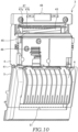
- FIG. 10 is a perspective view showing an outer surface of the cutter unit 3 in the open state.
- the cutter unit 3 can be opened to about 180 degrees by rotating the cutter unit cover 5 about the opening and closing shaft 41 with respect to the cutter unit body 4.
- the front surface guide portion 51a guides the print surface (the front surface) of the print medium M.
- the front surface guide portion 51a is formed in a convex curved surface shape with respect to the print medium M so as to gradually approach the back surface guide portion 51b from upstream to downstream in the feed direction of the print medium M. For this reason, it is difficult for the front surface guide portion 51a to be seen at a position further back from the discharge port 51, and it is difficult to perform cleaning by inserting a cotton swab or the like into the discharge port 51 from the front side of the cutter unit 3.
- the back surface guide portion 51b guides the surface (the back surface) opposite to the print surface of the print medium M.
- the back surface guide portion 51b is formed in a planar shape along the feed direction of the print medium M.
- the print medium M is provided with an adhesive for sticking to an adherend.
- the adhesive may adhere to the front surface guide portion 51a and the back surface guide portion 51b. For this reason, in order to remove the adhesive adhering to the front surface guide portion 51a and the back surface guide portion 51b, it is necessary to periodically clean the front surface guide portion 51a and the back surface guide portion 51b.
- the cutter unit cover 5 When the cutter unit cover 5 is in the closed state, even if the cotton swab or the like is inserted through the discharge port 51, only a part of the discharge port 51 can be cleaned. In contrast, when the cutter unit cover 5 is in the open state, the discharge port 51 is exposed more largely than when the cutter unit cover 5 is in the closed state. This facilitates cleaning of the front surface guide portion 51a and the back surface guide portion 51b.
- the cutter unit 3 includes the cutter unit body 4 that holds the movable blade 43 and the cutter unit cover 5 having the discharge port 51 configured to allow the print medium M to be discharged therethrough, and the cutter unit cover 5 is pivotally supported by the opening and closing shaft 41 so as to be openable and closable with respect to the cutter unit body 4. For this reason, when the cutter unit cover 5 is in the open state, the surface of the movable blade 43 facing the cutter unit cover 5 can be easily cleaned. Therefore, the cutter unit body 4 and the cutter unit cover 5 can be integrated into one unit, and the movable blade 43 can be easily cleaned.
- the cutter unit body 4 has the opening 45 through which a part of a surface of the movable blade 43 facing the printer body 2 is exposed. For this reason, a part of the movable blade 43 exposed from the opening 45 can be cleaned. Accordingly, not only the surface of the movable blade 43 facing the cutter unit cover 5 but also the surface of the movable blade 43 facing the printer body 2 can be easily cleaned, and the cleanable region of the movable blade 43 increases.
- the printer 1 includes the cutter unit 3 that is attachable to and detachable from the printer body 2, and the cutter unit 3 includes the cutter unit body 4 that holds the movable blade 43 that cuts the print medium M, and the cutter unit cover 5 that has the discharge port 51 through which the print medium M is discharged and is pivotally supported by the opening and closing shaft 41 so as to be openable and closable with respect to the cutter unit body 4.
- the cutter unit 3 includes the cutter unit body 4 that holds the movable blade 43 and the cutter unit cover 5 having the discharge port 51 through which the print medium M is discharged, and the cutter unit cover 5 is pivotally supported by the opening and closing shaft 41 so as to be openable and closable with respect to the cutter unit body 4. For this reason, when the cutter unit cover 5 is in the open state, the surface of the movable blade 43 facing the cutter unit cover 5 can be easily cleaned. Therefore, the cutter unit body 4 and the cutter unit cover 5 can be integrated into one unit, and the movable blade 43 can be easily cleaned.
- the print medium M has the adhesive and the adhesive adhering to the cutter unit 3 is cleaned has been described, but the print medium M may not have the adhesive.
- the cutter unit 3 openable and closable, it is possible to easily clean chips or the like generated when the print medium M is cut by the cutter unit 3.
Landscapes
- Life Sciences & Earth Sciences (AREA)
- Forests & Forestry (AREA)
- Engineering & Computer Science (AREA)
- Mechanical Engineering (AREA)
- Handling Of Sheets (AREA)
Abstract
Description
- The present invention relates to a printer and a cutter unit of the printer.
-
JP2006-335016A - Some labels are provided with an adhesive for sticking to an adherend. When such a label is cut with a cutter blade, the adhesive may adhere to the cutter blade. For this reason, in order to remove the adhesive adhering to the cutter blade, it is necessary to periodically clean the cutter blade.
- In the printer described in
JP2006-335016A - Therefore, the present inventor has proposed that the cutter unit body and the cutter unit cover are integrated into one unit.
- However, when the cutter unit body and the cutter unit cover are integrated into one unit, it is difficult to clean a surface of the cutter blade facing the cutter unit cover.
- The present invention has been made in view of the above problems, and an object of the present invention is to integrate a cutter unit body and a cutter unit cover into one unit and facilitate cleaning of a cutter blade.
- According to one aspect of the present invention, a printer includes a cutter unit attachable to and detachable from a printer body, wherein the cutter unit includes a cutter unit body configured to hold a cutter blade that cuts a print medium, and a cutter unit cover having a discharge port configured to allow the print medium to be discharged therethrough, and pivotally supported by an opening and closing shaft so as to be openable and closable with respect to the cutter unit body.
- In the aspect, the cutter unit includes the cutter unit body that holds the cutter blade and the cutter unit cover having the discharge port configured to allow the print medium to be discharged therethrough, and the cutter unit cover is pivotally supported by the opening and closing shaft so as to be openable and closable with respect to the cutter unit body. For this reason, when the cutter unit cover is in an open state, a surface of the cutter blade facing the cutter unit cover can be easily cleaned. Therefore, the cutter unit body and the cutter unit cover can be integrated into one unit, and the cutter blade can be easily cleaned.
-
- [
FIG. 1] FIG. 1 is a perspective view of a printer according to an embodiment of the present invention. - [
FIG. 2A] FIG. 2A is a perspective view of an example of a linerless print medium of the printer. - [
FIG. 2B] FIG. 2B is a perspective view of an example of the print medium used for continuous issue and peel-off issue of the printer. - [
FIG. 3] FIG. 3 is a schematic configuration diagram showing a configuration of a main part of the printer. - [
FIG. 4] FIG. 4 is a perspective view showing a state in which a cutter unit is detached from the printer. - [
FIG. 5] FIG. 5 is a front perspective view of the cutter unit. - [
FIG. 6] FIG. 6 is a rear perspective view of the cutter unit. - [
FIG. 7] FIG. 7 is a front perspective view showing a state in which the cutter unit shown inFIG. 5 is opened. - [
FIG. 8] FIG. 8 is a perspective view showing a state in which a protective cover is detached from the printer. - [
FIG. 9] FIG. 9 is a perspective view showing an inner surface of the cutter unit in an open state. - [
FIG. 10] FIG. 10 is a perspective view showing an outer surface of the cutter unit in the open state. - Hereinafter, a
printer 1 according to an embodiment of the present invention will be described with reference toFIGS. 1 to 10 . - First, an overall configuration of the
printer 1 will be described with reference toFIGS. 1 to 8 . -
FIG. 1 is a perspective view of theprinter 1.FIG. 2A is a perspective view of an example of a linerless print medium M of theprinter 1.FIG. 2B is a perspective view of an example of the print medium M used for continuous issue and peel-off issue of theprinter 1.FIG. 3 is a schematic configuration diagram showing a configuration of a main part of theprinter 1.FIG. 4 is a perspective view showing a state in which acutter unit 3 is detached from theprinter 1.FIG. 5 is a front perspective view of thecutter unit 3.FIG. 6 is a rear perspective view of thecutter unit 3.FIG. 7 is a front perspective view showing a state in which thecutter unit 3 shown inFIG. 5 is opened.FIG. 8 is a perspective view showing a state in which aprotective cover 6 is detached from theprinter 1. - As shown in
FIG. 1 , theprinter 1 includes aprinter body 2 and thecutter unit 3. Theprinter 1 is a direct thermal printer that performs printing by heating the print medium M (seeFIGS. 2A and 2B ) that is thermal paper coated with a thermosensitive color developing agent that develops color when a predetermined temperature range is reached. Hereinafter, a direction along a longitudinal direction (a feed direction) of the print medium M to be fed is also referred to as a "front-rear direction", a direction along a width direction of the print medium M is also referred to as a "left-right direction", and a direction along a thickness direction of the print medium M to be fed is also referred to as an "up-down direction". - As shown in
FIG. 2A , the print medium M is held by a paper tube PT in a state of being wound in a roll shape. The print medium M is a continuous linerless label NSP. As the print medium M, a continuous label SP having a liner sheet PB may be used. - As shown in
FIG. 2A , in the continuous linerless label NSP, a print surface (a front surface) of long thermal paper wound in a roll shape is coated with a release agent such as silicone, and a surface (a back surface) opposite to the print surface is coated with an adhesive for sticking to an adherend. In the continuous linerless label NSP, perforations PF may be formed at predetermined intervals. In this case, each region partitioned by the perforations PF constitutes one label LB. A black strip-shaped timing mark TM used for detecting a position of the label LB is formed on the back surface of the thermal paper. - As shown in
FIG. 2B , the continuous label SP includes the long liner sheet PB wound in a roll shape and a plurality of labels LB temporarily attached to a front surface of the liner sheet PB at predetermined intervals. The label LB temporarily attached to the front surface of the liner sheet PB is a thermal label in which a print surface (a front surface) is coated with a thermosensitive color developing agent and a surface (a back surface) opposite to the print surface is coated with an adhesive. In addition, a gap G of about 3 millimeters, which is a region where the liner sheet PB is exposed, is provided between a pair of adjacent labels LB. Further, the black strip-shaped timing mark TM used for detecting a position of the label LB is formed on a back surface of the liner sheet PB. The front surface of the liner sheet PB is coated with a release agent such as silicone to facilitate the peeling of the label LB. - As shown in
FIG. 1 ,FIG. 3 , andFIG. 4 , theprinter body 2 includes ahousing 21, aprinter cover 22, atouch panel display 23, anaccommodation portion 24, aplaten roller 25 serving as a feed roller, athermal head 26, a firstauxiliary roller 27a, a secondauxiliary roller 27b, aguide member 28, and a cutterunit attachment portion 29. - As shown in
FIG. 1 , thehousing 21 constitutes an outer shape of theprinter body 2. As shown inFIG. 4 , thehousing 21 is provided with theaccommodation portion 24, the firstauxiliary roller 27a, theplaten roller 25, theguide member 28, and the cutterunit attachment portion 29. Thehousing 21 is provided with a lock mechanism (not shown) for maintaining theprinter cover 22 in a closed state. The lock mechanism is released by operating a lever 11 (seeFIG. 1 ) provided on theprinter cover 22. - As shown in
FIG. 1 , theprinter cover 22 covers a part of thehousing 21. As shown inFIGS. 1 and3 , theprinter cover 22 is provided with thetouch panel display 23, thethermal head 26, and the secondauxiliary roller 27b. Theprinter cover 22 is swingably supported at one end by a support shaft (not shown) provided on thehousing 21. Theprinter cover 22 can be switched between an open state (refer toFIG. 4 ) in which each component accommodated in anopening 21a formed in a part of thehousing 21 is opened and a closed state (refer toFIG. 1 ) in which each component is closed by swinging about the support shaft as a fulcrum. - As shown in
FIG. 1 , thetouch panel display 23 is provided on an outer surface of theprinter cover 22. Thetouch panel display 23 is disposed on an upper surface of theprinter cover 22 in the closed state. Thetouch panel display 23 is configured to display predetermined information. The predetermined information includes information on theprinter 1 and an operation key image. When a user touches the operation key image, a processor of theprinter 1 receives an instruction corresponding to the operation key image. Thetouch panel display 23 is, for example, a liquid crystal display having a touch sensor. - As shown in
FIG. 3 , theaccommodation portion 24 is located on the support shaft side of thehousing 21. Theaccommodation portion 24 is configured to accommodate the print medium M. When theprinter cover 22 is in the open state, theaccommodation portion 24 can be accessed from an outside of theprinter 1 through theopening 21a. Accordingly, the user can set the print medium M in theaccommodation portion 24. - The
platen roller 25 is disposed on a surface (an upper surface) of thehousing 21 facing theprinter cover 22, and is exposed at theopening 21a. Theplaten roller 25 is located downstream of the firstauxiliary roller 27a in the feed direction of the print medium M. Theplaten roller 25 is pivotally supported by thehousing 21. That is, theplaten roller 25 is rotatable with respect to thehousing 21. Theplaten roller 25 is connected to a stepping motor (not shown). Theplaten roller 25 feeds the print medium M by rotating with respect to thehousing 21 under the control of the stepping motor. - The
thermal head 26 is disposed on a surface (a lower surface) of theprinter cover 22 facing thehousing 21. Thethermal head 26 is located downstream of the secondauxiliary roller 27b in the feed direction of the print medium M. Thethermal head 26 includes a plurality of heating elements (not shown) that generate Joule heat when energized. Thethermal head 26 is connected to a control circuit (not shown). Each heating element generates heat under the control of the control circuit. Thethermal head 26 constitutes a printing unit that performs printing on the print medium M together with theplaten roller 25 provided on thehousing 21 side. Thethermal head 26 is separated from theplaten roller 25 when theprinter cover 22 is in the open state. Thethermal head 26 faces theplaten roller 25 when theprinter cover 22 is in the closed state. The print medium M printed by thethermal head 26 is fed to thecutter unit 3 by the rotation of theplaten roller 25. - The first
auxiliary roller 27a is disposed on the surface (the upper surface) of thehousing 21 facing theprinter cover 22, and is exposed at theopening 21a. The firstauxiliary roller 27a is located downstream of theaccommodation portion 24 in the feed direction of the print medium M. The firstauxiliary roller 27a is pivotally supported by thehousing 21. That is, the firstauxiliary roller 27a is rotatable with respect to thehousing 21. - The second
auxiliary roller 27b is disposed on the surface (the lower surface) of theprinter cover 22 facing thehousing 21. The secondauxiliary roller 27b is located downstream of theaccommodation portion 24 in the feed direction of the print medium M. The secondauxiliary roller 27b is pivotally supported by theprinter cover 22. That is, the secondauxiliary roller 27b is rotatable with respect to theprinter cover 22. The secondauxiliary roller 27b is separated from the firstauxiliary roller 27a when theprinter cover 22 is in the open state. The secondauxiliary roller 27b faces the firstauxiliary roller 27a and rotates while nipping the print medium M when theprinter cover 22 is in the closed state. The firstauxiliary roller 27a and the secondauxiliary roller 27b assist in feeding the print medium M from theaccommodation portion 24 to theplaten roller 25. - As shown in
FIG. 4 , theguide member 28 is provided in a feed path of the print medium M including the firstauxiliary roller 27a and theplaten roller 25, and is exposed at theopening 21a. Theguide member 28 is a substantially flat plate-shaped resin member that guides the print medium M to be fed by the firstauxiliary roller 27a and theplaten roller 25. Theguide member 28 includes a pair of protruding ends 28a. - The pair of protruding ends 28a protrude forward from both ends of the
guide member 28 in the left-right direction. Each of the protruding ends 28a is provided so as to cover an upper surface of apin holder 31 to be described later of thehousing 21 into which a pin 52 (seeFIGS. 5 and6 ) of thecutter unit 3 is inserted. Since theprotruding end 28a is a resin member, theprotruding end 28a can be elastically deformed by being pressed downward by the user. When theprotruding end 28a is pressed downward, theprotruding end 28a presses thepin 52 in an axial direction, and allows thepin 52 to move in a direction of retracting from thepin holder 31. Accordingly, thepin 52 can be detached from thepin holder 31, and thecutter unit 3 can be detached from the cutterunit attachment portion 29. - The cutter
unit attachment portion 29 is provided on a front surface of thehousing 21. Thecutter unit 3 is detachably attached to the cutterunit attachment portion 29. The cutterunit attachment portion 29 includes ashaft support 30 serving as a first support, a pair ofpin holders 31 serving as a second support, and aterminal portion 32. - The
shaft support 30 supports an opening and closing shaft 41 (seeFIGS. 5 and6 ) to be described later of thecutter unit 3. A pair of shaft supports 30 are provided to face each other so as to support both ends of the opening and closingshaft 41 extending in the left-right direction of thehousing 21. Theshaft support 30 is formed to have substantially the same inner diameter as an outer diameter of the opening and closingshaft 41 at a minimum diameter position. Theshaft support 30 is formed so as to gradually increase in diameter inward in the left-right direction. This facilitates insertion of the opening and closingshaft 41 into theshaft support 30. - The
pin holder 31 holds thepin 52 to be described later (seeFIGS. 5 and6 ) of thecutter unit 3. Thepin holder 31 is a through hole that extends along the up-down direction of thehousing 21. Thepin holder 31 is formed to have substantially the same inner diameter as an outer diameter of thepin 52. The pair ofpin holders 31 are provided at positions separated from each other in the left-right direction. Theprotruding end 28a of theguide member 28 is disposed on an upper surface of thepin holder 31. - The
cutter unit 3 is attached to the cutterunit attachment portion 29 in a state in which theshaft support 30 supports the opening and closingshaft 41 and thepin holder 31 holds thepin 52. - The
terminal portion 32 includes a plurality of electrodes electrically connected to thecutter unit 3 to transmit and receive electric signals. For example, a signal or the like corresponding to a timing of cutting the print medium M is transmitted from theprinter body 2 to thecutter unit 3 through theterminal portion 32. - The
cutter unit 3 is detachably attached to theprinter body 2. Specifically, thecutter unit 3 is detachably attached to the cutterunit attachment portion 29 of theprinter body 2. As shown inFIGS. 5 and6 , thecutter unit 3 includes acutter unit body 4, acutter unit cover 5, and theprotective cover 6. - Here, the print medium M is provided with an adhesive for sticking to an adherend. When the print medium M is cut by a
movable blade 43, the adhesive may adhere to themovable blade 43. For this reason, in order to remove the adhesive adhering to themovable blade 43, it is necessary to periodically clean themovable blade 43. Therefore, in theprinter 1, thecutter unit 3 has a structure in which thecutter unit body 4 and thecutter unit cover 5 can be opened and closed. A case where thecutter unit body 4 and thecutter unit cover 5 are in the open state will be described in detail later with reference toFIGS. 9 and10 . - The
cutter unit body 4 is formed in a substantially rectangular shape. Thecutter unit body 4 includes the opening and closingshaft 41, a fixedblade 42, amovable blade 43 serving as a cutter blade, acutter drive mechanism 44, anopening 45, aterminal portion 46, and an engagementconvex portion 48. - As shown in
FIGS. 5 to 7 , the opening and closingshaft 41 protrudes outward in the left-right direction from thecutter unit body 4. The opening and closingshaft 41 is formed in a substantially cylindrical shape. Since the opening and closingshaft 41 is supported by theprinter body 2, thecutter unit 3 is attached to theprinter body 2. - As shown in
FIG. 7 , the fixedblade 42 is fixed to thecutter unit body 4. A tip of the fixedblade 42 is formed substantially horizontally in the left-right direction. - The
movable blade 43 is held by thecutter unit body 4. A tip of themovable blade 43 is formed obliquely so as to be inclined in the left-right direction. Themovable blade 43 is movable relative to the fixedblade 42. When themovable blade 43 moves toward the fixedblade 42, the print medium M is cut. After cutting the print medium M between themovable blade 43 and the fixedblade 42, themovable blade 43 retreats in a direction away from the fixedblade 42. Themovable blade 43 is driven by thecutter drive mechanism 44. - As shown in
FIG. 3 , thecutter drive mechanism 44 includes arack gear 44a and a pinion gear 44b. - The
movable blade 43 is fixed to therack gear 44a. Therack gear 44a is provided to be movable in the longitudinal direction. As therack gear 44a moves, themovable blade 43 also moves integrally. - The pinion gear 44b is connected to an electric motor (not shown). The pinion gear 44b moves the
rack gear 44a by rotating under the control of the electric motor. A part of the pinion gear 44b is exposed to the outside from thecutter unit body 4. Accordingly, when cleaning themovable blade 43, the user manually rotates the pinion gear 44b to move themovable blade 43, thereby allowing themovable blade 43 to be largely exposed. - As shown in
FIG. 6 , theopening 45 is an opening for exposing a part of a surface of themovable blade 43 facing theprinter body 2. - The
terminal portion 46 includes a plurality of pins that are respectively in contact with the plurality of electrodes of theterminal portion 32 of theprinter body 2. Theterminal portion 46 is electrically connected to theterminal portion 32 while being in contact therewith. For this reason, theterminal portion 46 is electrically connected to theterminal portion 32 only by attaching thecutter unit 3 to theprinter body 2. As described above, theterminal portion 46 is not a harness but a pin that is electrically connected to theterminal portion 32 in a state in which thecutter unit 3 is attached to theprinter body 2 and is in contact with the electrodes of theterminal portion 32. Accordingly, in a state in which thecutter unit 3 is detached from theprinter body 2, theterminal portion 46 is separated from theterminal portion 32 and power is not supplied to thecutter unit 3, and thus there is no risk of an erroneous operation. However, a configuration in which thecutter unit 3 and theprinter body 2 are electrically connected by a harness may be adopted. - A
guide plate 47 guides the print medium M when the user sets the print medium M in thecutter unit 3. Theguide plate 47 includes afirst plate portion 47a and asecond plate portion 47b. Thefirst plate portion 47a is provided above thesecond plate portion 47b. Thefirst plate portion 47a and thesecond plate portion 47b are provided obliquely such that a distance therebetween increases as thefirst plate portion 47a and thesecond plate portion 47b are separated from thecutter unit body 4. Accordingly, since the distance between thefirst plate portion 47a and thesecond plate portion 47b is the largest at an entrance of the print medium M, the user can easily insert the print medium M. - As shown in
FIG. 7 , the engagementconvex portion 48 protrudes upward from an upper portion of thecutter unit body 4. The engagementconvex portion 48 engages with an engagementconcave portion 54 of thecutter unit cover 5 when thecutter unit cover 5 is in the closed state. - As shown in
FIGS. 5 to 8 , thecutter unit cover 5 is formed in a substantially rectangular shape. Thecutter unit cover 5 is larger than thecutter unit body 4 and has substantially the same size as the cutterunit attachment portion 29. Thecutter unit cover 5 is supported by the opening and closingshaft 41 so as to be openable and closable with respect to thecutter unit body 4. That is, thecutter unit cover 5 is rotatable about the opening and closingshaft 41 with respect to thecutter unit body 4. Thecutter unit cover 5 includes adischarge port 51, a pair ofpins 52 serving as held portions, a support 53 (seeFIG. 8 ), and the engagementconcave portion 54. - The
discharge port 51 is a rectangular opening through which a label LB obtained by cutting the print medium M with the fixedblade 42 and themovable blade 43 is discharged. Thedischarge port 51 has a frontsurface guide portion 51a as a first guide portion and a backsurface guide portion 51b as a second guide portion (seeFIG. 9 ). The frontsurface guide portion 51a and the backsurface guide portion 51b will be described in detail later with reference toFIG. 9 . - Each of the
pins 52 is held on theprinter body 2 at a position separated from the opening and closingshaft 41 in a state in which the opening and closingshaft 41 is supported by theprinter body 2. Thepin 52 is biased by aspring 52a serving as a biasing member in a direction (an extension direction) of insertion into thepin holder 31. - When attaching the
cutter unit 3 to theprinter body 2, the user inserts the opening and closingshaft 41 of thecutter unit 3 into theshaft support 30 of theprinter body 2, and then rotates thecutter unit 3 about the opening and closingshaft 41 to insert thecutter unit 3 into the cutterunit attachment portion 29. Thecutter unit 3 is pressed against theprinter body 2 to insert thepin 52 into thepin holder 31. At this time, thepin 52 is inserted into thepin holder 31 as thecompressed spring 52a returns to an original state thereof due to restoring force. Accordingly, thecutter unit 3 is attached to theprinter body 2. - The opening and closing
shaft 41 is supported by theshaft support 30 of theprinter body 2 and thepin 52 provided on thecutter unit cover 5 is held by thepin holder 31 of theprinter body 2, whereby thecutter unit 3 is attached to theprinter body 2. During the operation of theprinter 1, theprinter cover 22 is in the closed state and thepin 52 cannot be pulled out from thepin holder 31, and thus thecutter unit cover 5 is not opened. That is, thecutter unit cover 5 is not opened when thecutter unit 3 is attached to theprinter body 2. Thus, the user cannot touch thecutter unit body 4 while theprinter 1 is printing and cutting the print medium M, and thus safety can be improved. - Further, when detaching the
cutter unit 3 from theprinter body 2, the user presses theprotruding end 28a of theguide member 28 downward to compress thespring 52a and then pulls out thepin 52 from thepin holder 31, and simultaneously rotates thecutter unit 3 about the opening and closingshaft 41 to pull out an upper end of thecutter unit 3 from the cutterunit attachment portion 29. Thecutter unit 3 is separated from the cutterunit attachment portion 29 such that the opening and closingshaft 41 is disengaged from theshaft support 30. Accordingly, thecutter unit 3 is detached from theprinter body 2. - The
support 53 shown inFIG. 8 is covered with theprotective cover 6 when not in use (seeFIG. 1 ). Thesupport 53 is accommodated in theprotective cover 6 in a folded state. As shown inFIG. 8 , thesupport 53 is exposed to the outside in a state in which theprotective cover 6 is detached. When thesupport 53 is raised from the folded state, thesupport 53 protrudes toward the front of theprinter 1. In a state in which thesupport 53 is raised, it is possible to prevent the print medium M cut by thecutter unit 3 after being printed from sticking to theprinter 1. - As shown in
FIG. 7 , the engagementconcave portion 54 is a rectangular hole that is formed in an upper portion of thecutter unit cover 5 and penetrates thecutter unit cover 5 in the up-down direction. When thecutter unit cover 5 is in the closed state, the engagementconvex portion 48 of thecutter unit body 4 is engaged with the engagementconcave portion 54. - As shown in
FIG. 1 , theprotective cover 6 is a cover for preventing a finger of the user or the like from being inserted through thedischarge port 51. By providing theprotective cover 6, the safety is improved. - Next, cleaning of the
cutter unit 3 will be described with reference toFIGS. 9 and10 . -
FIG. 9 is a perspective view showing an inner surface of thecutter unit 3 in the open state.FIG. 10 is a perspective view showing an outer surface of thecutter unit 3 in the open state. - As shown in
FIGS. 9 and10 , thecutter unit 3 can be opened to about 180 degrees by rotating thecutter unit cover 5 about the opening and closingshaft 41 with respect to thecutter unit body 4. - As shown in
FIG. 9 , when thecutter unit cover 5 is in the open state, the frontsurface guide portion 51a and the backsurface guide portion 51b of thedischarge port 51 are completely exposed, and surfaces of the fixedblade 42 and themovable blade 43 facing thecutter unit cover 5 are largely exposed. - The front
surface guide portion 51a guides the print surface (the front surface) of the print medium M. The frontsurface guide portion 51a is formed in a convex curved surface shape with respect to the print medium M so as to gradually approach the backsurface guide portion 51b from upstream to downstream in the feed direction of the print medium M. For this reason, it is difficult for the frontsurface guide portion 51a to be seen at a position further back from thedischarge port 51, and it is difficult to perform cleaning by inserting a cotton swab or the like into thedischarge port 51 from the front side of thecutter unit 3. - The back
surface guide portion 51b guides the surface (the back surface) opposite to the print surface of the print medium M. The backsurface guide portion 51b is formed in a planar shape along the feed direction of the print medium M. - The print medium M is provided with an adhesive for sticking to an adherend. When the print medium M repeatedly passes, the adhesive may adhere to the front
surface guide portion 51a and the backsurface guide portion 51b. For this reason, in order to remove the adhesive adhering to the frontsurface guide portion 51a and the backsurface guide portion 51b, it is necessary to periodically clean the frontsurface guide portion 51a and the backsurface guide portion 51b. - In contrast, in the
cutter unit 3, when thecutter unit cover 5 is in the open state, the frontsurface guide portion 51a and the backsurface guide portion 51b of thedischarge port 51 are completely exposed, and thus the frontsurface guide portion 51a and the backsurface guide portion 51b are easily cleaned. - When the
cutter unit cover 5 is in the closed state, even if the cotton swab or the like is inserted through thedischarge port 51, only a part of thedischarge port 51 can be cleaned. In contrast, when thecutter unit cover 5 is in the open state, thedischarge port 51 is exposed more largely than when thecutter unit cover 5 is in the closed state. This facilitates cleaning of the frontsurface guide portion 51a and the backsurface guide portion 51b. - When the
cutter unit cover 5 is in the closed state, a part of themovable blade 43 is seen from thedischarge port 51. However, even if the cotton swab or the like is inserted from thedischarge port 51, only a part of themovable blade 43 can be cleaned. In contrast, when thecutter unit cover 5 is in the open state, the surface of themovable blade 43 facing thecutter unit cover 5 is exposed more largely than when thecutter unit cover 5 is in the closed state. Accordingly, cleaning of the surface of themovable blade 43 facing thecutter unit cover 5 is facilitated, and a cleanable region of themovable blade 43 is increased. - As described above, the
cutter unit 3 includes thecutter unit body 4 that holds themovable blade 43 and thecutter unit cover 5 having thedischarge port 51 configured to allow the print medium M to be discharged therethrough, and thecutter unit cover 5 is pivotally supported by the opening and closingshaft 41 so as to be openable and closable with respect to thecutter unit body 4. For this reason, when thecutter unit cover 5 is in the open state, the surface of themovable blade 43 facing thecutter unit cover 5 can be easily cleaned. Therefore, thecutter unit body 4 and thecutter unit cover 5 can be integrated into one unit, and themovable blade 43 can be easily cleaned. - In the
printer 1, it is not necessary to use a tool when the cutter unit is detached from the cutterunit attachment portion 29 of theprinter body 2 and when thecutter unit cover 5 is in the open state, and thus workability is good. - As shown in
FIG. 10 , thecutter unit body 4 has theopening 45 through which a part of a surface of themovable blade 43 facing theprinter body 2 is exposed. For this reason, a part of themovable blade 43 exposed from theopening 45 can be cleaned. Accordingly, not only the surface of themovable blade 43 facing thecutter unit cover 5 but also the surface of themovable blade 43 facing theprinter body 2 can be easily cleaned, and the cleanable region of themovable blade 43 increases. - According to the above embodiment, the following effects are achieved.
- The
printer 1 includes thecutter unit 3 that is attachable to and detachable from theprinter body 2, and thecutter unit 3 includes thecutter unit body 4 that holds themovable blade 43 that cuts the print medium M, and thecutter unit cover 5 that has thedischarge port 51 through which the print medium M is discharged and is pivotally supported by the opening and closingshaft 41 so as to be openable and closable with respect to thecutter unit body 4. - In the configuration, the
cutter unit 3 includes thecutter unit body 4 that holds themovable blade 43 and thecutter unit cover 5 having thedischarge port 51 through which the print medium M is discharged, and thecutter unit cover 5 is pivotally supported by the opening and closingshaft 41 so as to be openable and closable with respect to thecutter unit body 4. For this reason, when thecutter unit cover 5 is in the open state, the surface of themovable blade 43 facing thecutter unit cover 5 can be easily cleaned. Therefore, thecutter unit body 4 and thecutter unit cover 5 can be integrated into one unit, and themovable blade 43 can be easily cleaned. - Although the embodiments of the present invention have been described above, the above-mentioned embodiments are merely a part of application examples of the present invention, and do not mean that the technical scope of the present invention is limited to the specific configurations of the above-mentioned embodiments.
- In the above embodiment, the case where the print medium M has the adhesive and the adhesive adhering to the
cutter unit 3 is cleaned has been described, but the print medium M may not have the adhesive. In this case, by making thecutter unit 3 openable and closable, it is possible to easily clean chips or the like generated when the print medium M is cut by thecutter unit 3. - The present application claims priority under
Japanese Patent Application No. 2022-011890 filed to the Japan Patent Office on January 28, 2022
Claims (10)
- A printer comprising:a cutter unit attachable to and detachable from a printer body, whereinthe cutter unit includesa cutter unit body configured to hold a cutter blade that cuts a print medium, anda cutter unit cover having a discharge port configured to allow the print medium to be discharged therethrough, and pivotally supported by an opening and closing shaft so as to be openable and closable with respect to the cutter unit body.
- The printer according to claim 1, wherein
when the cutter unit cover is in an open state, a surface of the cutter blade facing the cutter unit cover is exposed more largely than when the cutter unit cover is in a closed state. - The printer according to claim 1 or 2, wherein
when the cutter unit cover is in the open state, the discharge port is exposed more largely than when the cutter unit cover is in the closed state. - The printer according to any one of claims 1 to 3, wherein
the cutter unit body has an opening configured to allow a part of a surface of the cutter blade facing the printer body to expose therethrough. - The printer according to any one of claims 1 to 4, wherein
the discharge port includes a first guide portion configured to guide a print surface of the print medium and a second guide portion configured to guide a surface opposite to the print surface of the print medium. - The printer according to any one of claims 1 to 5, wherein
the cutter unit is attached to the printer body by the opening and closing shaft being supported by the printer body. - The printer according to claim 6, wherein
the cutter unit cover includes a held portion configured to hold the cutter unit cover on the printer body at a position separated from the opening and closing shaft in a state in which the opening and closing shaft is supported by the printer body. - The printer according to any one of claims 1 to 7, wherein
the cutter unit cover is not in an open state in a state in which the cutter unit is attached to the printer body. - The printer according to any one of claims 1 to 8, wherein
the cutter unit body includes a terminal portion electrically connected in a state of being in contact with an electrode of the printer body when the cutter unit body is attached to the printer body. - A cutter unit of a printer attachable to and detachable from a printer body, the cutter unit comprising:a cutter unit body configured to hold a cutter blade that cuts a print medium; anda cutter unit cover having a discharge port configured to allow the print medium to be discharged therethrough, and pivotally supported by an opening and closing shaft so as to be openable and closable with respect to the cutter unit body.
Applications Claiming Priority (2)
| Application Number | Priority Date | Filing Date | Title |
|---|---|---|---|
| JP2022011890A JP7813147B2 (en) | 2022-01-28 | 2022-01-28 | Printer and printer cutter unit |
| PCT/JP2022/038646 WO2023145157A1 (en) | 2022-01-28 | 2022-10-17 | Printer and cutter unit of printer |
Publications (2)
| Publication Number | Publication Date |
|---|---|
| EP4470788A1 true EP4470788A1 (en) | 2024-12-04 |
| EP4470788A4 EP4470788A4 (en) | 2025-05-21 |
Family
ID=87471084
Family Applications (1)
| Application Number | Title | Priority Date | Filing Date |
|---|---|---|---|
| EP22924013.0A Pending EP4470788A4 (en) | 2022-01-28 | 2022-10-17 | PRINTER AND PRINTER CUTTING UNIT |
Country Status (5)
| Country | Link |
|---|---|
| US (1) | US12583240B2 (en) |
| EP (1) | EP4470788A4 (en) |
| JP (1) | JP7813147B2 (en) |
| CN (1) | CN118475476A (en) |
| WO (1) | WO2023145157A1 (en) |
Families Citing this family (1)
| Publication number | Priority date | Publication date | Assignee | Title |
|---|---|---|---|---|
| US20250319707A1 (en) * | 2024-04-12 | 2025-10-16 | Zebra Technologies Corporation | Pivoting Cutter |
Family Cites Families (16)
| Publication number | Priority date | Publication date | Assignee | Title |
|---|---|---|---|---|
| JPS58125053U (en) * | 1982-02-19 | 1983-08-25 | 株式会社富士通ゼネラル | Printer cover support device |
| JP2999888B2 (en) * | 1991-11-29 | 2000-01-17 | 東芝テック株式会社 | Printer with cutter |
| JP3812761B2 (en) * | 1996-09-27 | 2006-08-23 | 株式会社サトー | Cutter unit mounting device |
| JP3250485B2 (en) * | 1997-05-12 | 2002-01-28 | 松下電器産業株式会社 | Printing device with cutter |
| US6102596A (en) | 1997-02-20 | 2000-08-15 | Matsushita Electric Industrial Co., Ltd. | Printing device with cutter |
| JP4562590B2 (en) | 2005-06-06 | 2010-10-13 | 東芝テック株式会社 | Printer |
| JP5327711B2 (en) * | 2009-06-11 | 2013-10-30 | ブラザー工業株式会社 | Print label production device |
| JP5411095B2 (en) | 2010-08-31 | 2014-02-12 | スター精密株式会社 | Printer |
| CN202053689U (en) * | 2011-02-22 | 2011-11-30 | 刘家利 | Sliding chute type integrated cutting knife and printer core structure composed thereof |
| JP2014104688A (en) | 2012-11-29 | 2014-06-09 | Sato Holdings Corp | Label printer |
| JP6016117B2 (en) * | 2013-01-31 | 2016-10-26 | ブラザー工業株式会社 | Tape printer |
| JP5835280B2 (en) * | 2013-06-28 | 2015-12-24 | 株式会社寺岡精工 | Printing device |
| JP6701633B2 (en) * | 2015-07-01 | 2020-05-27 | 株式会社寺岡精工 | Cutter device and paper issuing device equipped with a cutter device |
| JP6697058B1 (en) | 2018-12-05 | 2020-05-20 | シチズン時計株式会社 | Printer |
| JP7093571B2 (en) | 2020-06-17 | 2022-06-30 | 株式会社寺岡精工 | Label cutting device, label issuing device |
| JP7630872B2 (en) | 2020-06-30 | 2025-02-18 | 日本無線株式会社 | Noise Update Circuit |
-
2022
- 2022-01-28 JP JP2022011890A patent/JP7813147B2/en active Active
- 2022-10-17 EP EP22924013.0A patent/EP4470788A4/en active Pending
- 2022-10-17 CN CN202280086533.9A patent/CN118475476A/en active Pending
- 2022-10-17 US US18/726,574 patent/US12583240B2/en active Active
- 2022-10-17 WO PCT/JP2022/038646 patent/WO2023145157A1/en not_active Ceased
Also Published As
| Publication number | Publication date |
|---|---|
| US12583240B2 (en) | 2026-03-24 |
| JP7813147B2 (en) | 2026-02-12 |
| JP2023110441A (en) | 2023-08-09 |
| WO2023145157A1 (en) | 2023-08-03 |
| CN118475476A (en) | 2024-08-09 |
| EP4470788A4 (en) | 2025-05-21 |
| US20250178364A1 (en) | 2025-06-05 |
Similar Documents
| Publication | Publication Date | Title |
|---|---|---|
| JP6011120B2 (en) | Sheet cartridge, label producing apparatus, and label producing apparatus control method | |
| EP0960819B1 (en) | Label printer | |
| EP3184314B1 (en) | Printer | |
| EP2448761B1 (en) | Tape cassette | |
| CN109414939B (en) | printer | |
| EP1674273B1 (en) | Tape printer | |
| CN116490372B (en) | Printer and method for replacing printing head of printer | |
| US12583240B2 (en) | Printer and cutter unit of printer | |
| JP3812761B2 (en) | Cutter unit mounting device | |
| JP2025116177A (en) | printer | |
| JP6257452B2 (en) | Printer | |
| CN116438082B (en) | printer | |
| JP2009255334A (en) | Printing device | |
| CN116507503B (en) | printer | |
| CN116547154A (en) | Printer with a printer body | |
| JP7785901B2 (en) | Thermal head | |
| JP7815760B2 (en) | printing device | |
| US12434876B2 (en) | Labeling apparatus and discharge portion and gripping portion thereof | |
| US20250289246A1 (en) | Printer and cutting unit | |
| JP2022080506A (en) | Printer |
Legal Events
| Date | Code | Title | Description |
|---|---|---|---|
| STAA | Information on the status of an ep patent application or granted ep patent |
Free format text: STATUS: THE INTERNATIONAL PUBLICATION HAS BEEN MADE |
|
| PUAI | Public reference made under article 153(3) epc to a published international application that has entered the european phase |
Free format text: ORIGINAL CODE: 0009012 |
|
| STAA | Information on the status of an ep patent application or granted ep patent |
Free format text: STATUS: REQUEST FOR EXAMINATION WAS MADE |
|
| 17P | Request for examination filed |
Effective date: 20240628 |
|
| AK | Designated contracting states |
Kind code of ref document: A1 Designated state(s): AL AT BE BG CH CY CZ DE DK EE ES FI FR GB GR HR HU IE IS IT LI LT LU LV MC ME MK MT NL NO PL PT RO RS SE SI SK SM TR |
|
| DAV | Request for validation of the european patent (deleted) | ||
| DAX | Request for extension of the european patent (deleted) | ||
| A4 | Supplementary search report drawn up and despatched |
Effective date: 20250425 |
|
| RIC1 | Information provided on ipc code assigned before grant |
Ipc: B41J 3/407 20060101ALI20250417BHEP Ipc: B26D 1/08 20060101ALI20250417BHEP Ipc: B41J 29/13 20060101ALI20250417BHEP Ipc: B41J 11/70 20060101AFI20250417BHEP |
|
| RAP3 | Party data changed (applicant data changed or rights of an application transferred) |
Owner name: SATO CORPORATION |