EP4470770A1 - Fiberglass board, rear cover, electronic device, and preparation method for fiberglass board - Google Patents
Fiberglass board, rear cover, electronic device, and preparation method for fiberglass board Download PDFInfo
- Publication number
- EP4470770A1 EP4470770A1 EP23844915.1A EP23844915A EP4470770A1 EP 4470770 A1 EP4470770 A1 EP 4470770A1 EP 23844915 A EP23844915 A EP 23844915A EP 4470770 A1 EP4470770 A1 EP 4470770A1
- Authority
- EP
- European Patent Office
- Prior art keywords
- glass fiber
- fibers
- fiber layer
- degrees
- layer
- Prior art date
- Legal status (The legal status is an assumption and is not a legal conclusion. Google has not performed a legal analysis and makes no representation as to the accuracy of the status listed.)
- Granted
Links
Images






Classifications
-
- B—PERFORMING OPERATIONS; TRANSPORTING
- B32—LAYERED PRODUCTS
- B32B—LAYERED PRODUCTS, i.e. PRODUCTS BUILT-UP OF STRATA OF FLAT OR NON-FLAT, e.g. CELLULAR OR HONEYCOMB, FORM
- B32B5/00—Layered products characterised by the non- homogeneity or physical structure, i.e. comprising a fibrous, filamentary, particulate or foam layer; Layered products characterised by having a layer differing constitutionally or physically in different parts
- B32B5/02—Layered products characterised by the non- homogeneity or physical structure, i.e. comprising a fibrous, filamentary, particulate or foam layer; Layered products characterised by having a layer differing constitutionally or physically in different parts characterised by structural features of a fibrous or filamentary layer
- B32B5/12—Layered products characterised by the non- homogeneity or physical structure, i.e. comprising a fibrous, filamentary, particulate or foam layer; Layered products characterised by having a layer differing constitutionally or physically in different parts characterised by structural features of a fibrous or filamentary layer characterised by the relative arrangement of fibres or filaments of different layers, e.g. the fibres or filaments being parallel or perpendicular to each other
-
- B—PERFORMING OPERATIONS; TRANSPORTING
- B29—WORKING OF PLASTICS; WORKING OF SUBSTANCES IN A PLASTIC STATE IN GENERAL
- B29C—SHAPING OR JOINING OF PLASTICS; SHAPING OF MATERIAL IN A PLASTIC STATE, NOT OTHERWISE PROVIDED FOR; AFTER-TREATMENT OF THE SHAPED PRODUCTS, e.g. REPAIRING
- B29C70/00—Shaping composites, i.e. plastics material comprising reinforcements, fillers or preformed parts, e.g. inserts
- B29C70/04—Shaping composites, i.e. plastics material comprising reinforcements, fillers or preformed parts, e.g. inserts comprising reinforcements only, e.g. self-reinforcing plastics
- B29C70/06—Fibrous reinforcements only
- B29C70/10—Fibrous reinforcements only characterised by the structure of fibrous reinforcements, e.g. hollow fibres
- B29C70/16—Fibrous reinforcements only characterised by the structure of fibrous reinforcements, e.g. hollow fibres using fibres of substantial or continuous length
- B29C70/20—Fibrous reinforcements only characterised by the structure of fibrous reinforcements, e.g. hollow fibres using fibres of substantial or continuous length oriented in a single direction, e.g. roofing or other parallel fibres
- B29C70/202—Fibrous reinforcements only characterised by the structure of fibrous reinforcements, e.g. hollow fibres using fibres of substantial or continuous length oriented in a single direction, e.g. roofing or other parallel fibres arranged in parallel planes or structures of fibres crossing at substantial angles, e.g. cross-moulding compound [XMC]
-
- B—PERFORMING OPERATIONS; TRANSPORTING
- B29—WORKING OF PLASTICS; WORKING OF SUBSTANCES IN A PLASTIC STATE IN GENERAL
- B29C—SHAPING OR JOINING OF PLASTICS; SHAPING OF MATERIAL IN A PLASTIC STATE, NOT OTHERWISE PROVIDED FOR; AFTER-TREATMENT OF THE SHAPED PRODUCTS, e.g. REPAIRING
- B29C70/00—Shaping composites, i.e. plastics material comprising reinforcements, fillers or preformed parts, e.g. inserts
- B29C70/04—Shaping composites, i.e. plastics material comprising reinforcements, fillers or preformed parts, e.g. inserts comprising reinforcements only, e.g. self-reinforcing plastics
- B29C70/28—Shaping operations therefor
- B29C70/30—Shaping by lay-up, i.e. applying fibres, tape or broadsheet on a mould, former or core; Shaping by spray-up, i.e. spraying of fibres on a mould, former or core
-
- B—PERFORMING OPERATIONS; TRANSPORTING
- B29—WORKING OF PLASTICS; WORKING OF SUBSTANCES IN A PLASTIC STATE IN GENERAL
- B29C—SHAPING OR JOINING OF PLASTICS; SHAPING OF MATERIAL IN A PLASTIC STATE, NOT OTHERWISE PROVIDED FOR; AFTER-TREATMENT OF THE SHAPED PRODUCTS, e.g. REPAIRING
- B29C70/00—Shaping composites, i.e. plastics material comprising reinforcements, fillers or preformed parts, e.g. inserts
- B29C70/04—Shaping composites, i.e. plastics material comprising reinforcements, fillers or preformed parts, e.g. inserts comprising reinforcements only, e.g. self-reinforcing plastics
- B29C70/28—Shaping operations therefor
- B29C70/40—Shaping or impregnating by compression not applied
- B29C70/42—Shaping or impregnating by compression not applied for producing articles of definite length, i.e. discrete articles
-
- B—PERFORMING OPERATIONS; TRANSPORTING
- B32—LAYERED PRODUCTS
- B32B—LAYERED PRODUCTS, i.e. PRODUCTS BUILT-UP OF STRATA OF FLAT OR NON-FLAT, e.g. CELLULAR OR HONEYCOMB, FORM
- B32B17/00—Layered products essentially comprising sheet glass, or glass, slag, or like fibres
- B32B17/02—Layered products essentially comprising sheet glass, or glass, slag, or like fibres in the form of fibres or filaments
-
- B—PERFORMING OPERATIONS; TRANSPORTING
- B32—LAYERED PRODUCTS
- B32B—LAYERED PRODUCTS, i.e. PRODUCTS BUILT-UP OF STRATA OF FLAT OR NON-FLAT, e.g. CELLULAR OR HONEYCOMB, FORM
- B32B37/00—Methods or apparatus for laminating, e.g. by curing or by ultrasonic bonding
- B32B37/10—Methods or apparatus for laminating, e.g. by curing or by ultrasonic bonding characterised by the pressing technique, e.g. using action of vacuum or fluid pressure
-
- B—PERFORMING OPERATIONS; TRANSPORTING
- B32—LAYERED PRODUCTS
- B32B—LAYERED PRODUCTS, i.e. PRODUCTS BUILT-UP OF STRATA OF FLAT OR NON-FLAT, e.g. CELLULAR OR HONEYCOMB, FORM
- B32B38/00—Ancillary operations in connection with laminating processes
- B32B38/08—Impregnating
-
- B—PERFORMING OPERATIONS; TRANSPORTING
- B32—LAYERED PRODUCTS
- B32B—LAYERED PRODUCTS, i.e. PRODUCTS BUILT-UP OF STRATA OF FLAT OR NON-FLAT, e.g. CELLULAR OR HONEYCOMB, FORM
- B32B5/00—Layered products characterised by the non- homogeneity or physical structure, i.e. comprising a fibrous, filamentary, particulate or foam layer; Layered products characterised by having a layer differing constitutionally or physically in different parts
- B32B5/02—Layered products characterised by the non- homogeneity or physical structure, i.e. comprising a fibrous, filamentary, particulate or foam layer; Layered products characterised by having a layer differing constitutionally or physically in different parts characterised by structural features of a fibrous or filamentary layer
- B32B5/08—Layered products characterised by the non- homogeneity or physical structure, i.e. comprising a fibrous, filamentary, particulate or foam layer; Layered products characterised by having a layer differing constitutionally or physically in different parts characterised by structural features of a fibrous or filamentary layer the fibres or filaments of a layer being of different substances, e.g. conjugate fibres, mixture of different fibres
-
- B—PERFORMING OPERATIONS; TRANSPORTING
- B32—LAYERED PRODUCTS
- B32B—LAYERED PRODUCTS, i.e. PRODUCTS BUILT-UP OF STRATA OF FLAT OR NON-FLAT, e.g. CELLULAR OR HONEYCOMB, FORM
- B32B5/00—Layered products characterised by the non- homogeneity or physical structure, i.e. comprising a fibrous, filamentary, particulate or foam layer; Layered products characterised by having a layer differing constitutionally or physically in different parts
- B32B5/22—Layered products characterised by the non- homogeneity or physical structure, i.e. comprising a fibrous, filamentary, particulate or foam layer; Layered products characterised by having a layer differing constitutionally or physically in different parts characterised by the presence of two or more layers which are next to each other and are fibrous, filamentary, formed of particles or foamed
- B32B5/24—Layered products characterised by the non- homogeneity or physical structure, i.e. comprising a fibrous, filamentary, particulate or foam layer; Layered products characterised by having a layer differing constitutionally or physically in different parts characterised by the presence of two or more layers which are next to each other and are fibrous, filamentary, formed of particles or foamed one layer being a fibrous or filamentary layer
- B32B5/26—Layered products characterised by the non- homogeneity or physical structure, i.e. comprising a fibrous, filamentary, particulate or foam layer; Layered products characterised by having a layer differing constitutionally or physically in different parts characterised by the presence of two or more layers which are next to each other and are fibrous, filamentary, formed of particles or foamed one layer being a fibrous or filamentary layer another layer next to it also being fibrous or filamentary
-
- B—PERFORMING OPERATIONS; TRANSPORTING
- B32—LAYERED PRODUCTS
- B32B—LAYERED PRODUCTS, i.e. PRODUCTS BUILT-UP OF STRATA OF FLAT OR NON-FLAT, e.g. CELLULAR OR HONEYCOMB, FORM
- B32B5/00—Layered products characterised by the non- homogeneity or physical structure, i.e. comprising a fibrous, filamentary, particulate or foam layer; Layered products characterised by having a layer differing constitutionally or physically in different parts
- B32B5/22—Layered products characterised by the non- homogeneity or physical structure, i.e. comprising a fibrous, filamentary, particulate or foam layer; Layered products characterised by having a layer differing constitutionally or physically in different parts characterised by the presence of two or more layers which are next to each other and are fibrous, filamentary, formed of particles or foamed
- B32B5/24—Layered products characterised by the non- homogeneity or physical structure, i.e. comprising a fibrous, filamentary, particulate or foam layer; Layered products characterised by having a layer differing constitutionally or physically in different parts characterised by the presence of two or more layers which are next to each other and are fibrous, filamentary, formed of particles or foamed one layer being a fibrous or filamentary layer
- B32B5/26—Layered products characterised by the non- homogeneity or physical structure, i.e. comprising a fibrous, filamentary, particulate or foam layer; Layered products characterised by having a layer differing constitutionally or physically in different parts characterised by the presence of two or more layers which are next to each other and are fibrous, filamentary, formed of particles or foamed one layer being a fibrous or filamentary layer another layer next to it also being fibrous or filamentary
- B32B5/262—Layered products characterised by the non- homogeneity or physical structure, i.e. comprising a fibrous, filamentary, particulate or foam layer; Layered products characterised by having a layer differing constitutionally or physically in different parts characterised by the presence of two or more layers which are next to each other and are fibrous, filamentary, formed of particles or foamed one layer being a fibrous or filamentary layer another layer next to it also being fibrous or filamentary characterised by one fibrous or filamentary layer being a woven fabric layer
- B32B5/263—Layered products characterised by the non- homogeneity or physical structure, i.e. comprising a fibrous, filamentary, particulate or foam layer; Layered products characterised by having a layer differing constitutionally or physically in different parts characterised by the presence of two or more layers which are next to each other and are fibrous, filamentary, formed of particles or foamed one layer being a fibrous or filamentary layer another layer next to it also being fibrous or filamentary characterised by one fibrous or filamentary layer being a woven fabric layer next to one or more woven fabric layers
-
- H—ELECTRICITY
- H04—ELECTRIC COMMUNICATION TECHNIQUE
- H04M—TELEPHONIC COMMUNICATION
- H04M1/00—Substation equipment, e.g. for use by subscribers
- H04M1/02—Constructional features of telephone sets
- H04M1/0202—Portable telephone sets, e.g. cordless phones, mobile phones or bar type handsets
-
- H—ELECTRICITY
- H05—ELECTRIC TECHNIQUES NOT OTHERWISE PROVIDED FOR
- H05K—PRINTED CIRCUITS; CASINGS OR CONSTRUCTIONAL DETAILS OF ELECTRIC APPARATUS; MANUFACTURE OF ASSEMBLAGES OF ELECTRICAL COMPONENTS
- H05K5/00—Casings, cabinets or drawers for electric apparatus
- H05K5/0086—Casings, cabinets or drawers for electric apparatus portable, e.g. battery operated apparatus
-
- H—ELECTRICITY
- H05—ELECTRIC TECHNIQUES NOT OTHERWISE PROVIDED FOR
- H05K—PRINTED CIRCUITS; CASINGS OR CONSTRUCTIONAL DETAILS OF ELECTRIC APPARATUS; MANUFACTURE OF ASSEMBLAGES OF ELECTRICAL COMPONENTS
- H05K5/00—Casings, cabinets or drawers for electric apparatus
- H05K5/02—Details
- H05K5/0217—Mechanical details of casings
- H05K5/0243—Mechanical details of casings for decorative purposes
-
- H—ELECTRICITY
- H05—ELECTRIC TECHNIQUES NOT OTHERWISE PROVIDED FOR
- H05K—PRINTED CIRCUITS; CASINGS OR CONSTRUCTIONAL DETAILS OF ELECTRIC APPARATUS; MANUFACTURE OF ASSEMBLAGES OF ELECTRICAL COMPONENTS
- H05K5/00—Casings, cabinets or drawers for electric apparatus
- H05K5/02—Details
- H05K5/03—Covers
-
- B—PERFORMING OPERATIONS; TRANSPORTING
- B32—LAYERED PRODUCTS
- B32B—LAYERED PRODUCTS, i.e. PRODUCTS BUILT-UP OF STRATA OF FLAT OR NON-FLAT, e.g. CELLULAR OR HONEYCOMB, FORM
- B32B2250/00—Layers arrangement
- B32B2250/20—All layers being fibrous or filamentary
-
- B—PERFORMING OPERATIONS; TRANSPORTING
- B32—LAYERED PRODUCTS
- B32B—LAYERED PRODUCTS, i.e. PRODUCTS BUILT-UP OF STRATA OF FLAT OR NON-FLAT, e.g. CELLULAR OR HONEYCOMB, FORM
- B32B2260/00—Layered product comprising an impregnated, embedded, or bonded layer wherein the layer comprises an impregnation, embedding, or binder material
- B32B2260/02—Composition of the impregnated, bonded or embedded layer
- B32B2260/021—Fibrous or filamentary layer
- B32B2260/023—Two or more layers
-
- B—PERFORMING OPERATIONS; TRANSPORTING
- B32—LAYERED PRODUCTS
- B32B—LAYERED PRODUCTS, i.e. PRODUCTS BUILT-UP OF STRATA OF FLAT OR NON-FLAT, e.g. CELLULAR OR HONEYCOMB, FORM
- B32B2260/00—Layered product comprising an impregnated, embedded, or bonded layer wherein the layer comprises an impregnation, embedding, or binder material
- B32B2260/04—Impregnation, embedding, or binder material
- B32B2260/046—Synthetic resin
-
- B—PERFORMING OPERATIONS; TRANSPORTING
- B32—LAYERED PRODUCTS
- B32B—LAYERED PRODUCTS, i.e. PRODUCTS BUILT-UP OF STRATA OF FLAT OR NON-FLAT, e.g. CELLULAR OR HONEYCOMB, FORM
- B32B2262/00—Composition or structural features of fibres which form a fibrous or filamentary layer or are present as additives
- B32B2262/02—Synthetic macromolecular fibres
- B32B2262/0261—Polyamide fibres
- B32B2262/0269—Aromatic polyamide fibres
-
- B—PERFORMING OPERATIONS; TRANSPORTING
- B32—LAYERED PRODUCTS
- B32B—LAYERED PRODUCTS, i.e. PRODUCTS BUILT-UP OF STRATA OF FLAT OR NON-FLAT, e.g. CELLULAR OR HONEYCOMB, FORM
- B32B2262/00—Composition or structural features of fibres which form a fibrous or filamentary layer or are present as additives
- B32B2262/10—Inorganic fibres
- B32B2262/101—Glass fibres
-
- B—PERFORMING OPERATIONS; TRANSPORTING
- B32—LAYERED PRODUCTS
- B32B—LAYERED PRODUCTS, i.e. PRODUCTS BUILT-UP OF STRATA OF FLAT OR NON-FLAT, e.g. CELLULAR OR HONEYCOMB, FORM
- B32B2262/00—Composition or structural features of fibres which form a fibrous or filamentary layer or are present as additives
- B32B2262/10—Inorganic fibres
- B32B2262/106—Carbon fibres, e.g. graphite fibres
-
- B—PERFORMING OPERATIONS; TRANSPORTING
- B32—LAYERED PRODUCTS
- B32B—LAYERED PRODUCTS, i.e. PRODUCTS BUILT-UP OF STRATA OF FLAT OR NON-FLAT, e.g. CELLULAR OR HONEYCOMB, FORM
- B32B2262/00—Composition or structural features of fibres which form a fibrous or filamentary layer or are present as additives
- B32B2262/14—Mixture of at least two fibres made of different materials
-
- B—PERFORMING OPERATIONS; TRANSPORTING
- B32—LAYERED PRODUCTS
- B32B—LAYERED PRODUCTS, i.e. PRODUCTS BUILT-UP OF STRATA OF FLAT OR NON-FLAT, e.g. CELLULAR OR HONEYCOMB, FORM
- B32B2307/00—Properties of the layers or laminate
- B32B2307/50—Properties of the layers or laminate having particular mechanical properties
-
- B—PERFORMING OPERATIONS; TRANSPORTING
- B32—LAYERED PRODUCTS
- B32B—LAYERED PRODUCTS, i.e. PRODUCTS BUILT-UP OF STRATA OF FLAT OR NON-FLAT, e.g. CELLULAR OR HONEYCOMB, FORM
- B32B2307/00—Properties of the layers or laminate
- B32B2307/50—Properties of the layers or laminate having particular mechanical properties
- B32B2307/514—Oriented
- B32B2307/518—Oriented bi-axially
-
- B—PERFORMING OPERATIONS; TRANSPORTING
- B32—LAYERED PRODUCTS
- B32B—LAYERED PRODUCTS, i.e. PRODUCTS BUILT-UP OF STRATA OF FLAT OR NON-FLAT, e.g. CELLULAR OR HONEYCOMB, FORM
- B32B2307/00—Properties of the layers or laminate
- B32B2307/50—Properties of the layers or laminate having particular mechanical properties
- B32B2307/558—Impact strength, toughness
-
- B—PERFORMING OPERATIONS; TRANSPORTING
- B32—LAYERED PRODUCTS
- B32B—LAYERED PRODUCTS, i.e. PRODUCTS BUILT-UP OF STRATA OF FLAT OR NON-FLAT, e.g. CELLULAR OR HONEYCOMB, FORM
- B32B2307/00—Properties of the layers or laminate
- B32B2307/50—Properties of the layers or laminate having particular mechanical properties
- B32B2307/58—Cuttability
- B32B2307/581—Resistant to cut
-
- B—PERFORMING OPERATIONS; TRANSPORTING
- B32—LAYERED PRODUCTS
- B32B—LAYERED PRODUCTS, i.e. PRODUCTS BUILT-UP OF STRATA OF FLAT OR NON-FLAT, e.g. CELLULAR OR HONEYCOMB, FORM
- B32B2363/00—Epoxy resins
-
- B—PERFORMING OPERATIONS; TRANSPORTING
- B32—LAYERED PRODUCTS
- B32B—LAYERED PRODUCTS, i.e. PRODUCTS BUILT-UP OF STRATA OF FLAT OR NON-FLAT, e.g. CELLULAR OR HONEYCOMB, FORM
- B32B2457/00—Electrical equipment
-
- B—PERFORMING OPERATIONS; TRANSPORTING
- B32—LAYERED PRODUCTS
- B32B—LAYERED PRODUCTS, i.e. PRODUCTS BUILT-UP OF STRATA OF FLAT OR NON-FLAT, e.g. CELLULAR OR HONEYCOMB, FORM
- B32B5/00—Layered products characterised by the non- homogeneity or physical structure, i.e. comprising a fibrous, filamentary, particulate or foam layer; Layered products characterised by having a layer differing constitutionally or physically in different parts
- B32B5/02—Layered products characterised by the non- homogeneity or physical structure, i.e. comprising a fibrous, filamentary, particulate or foam layer; Layered products characterised by having a layer differing constitutionally or physically in different parts characterised by structural features of a fibrous or filamentary layer
- B32B5/024—Woven fabric
-
- H—ELECTRICITY
- H04—ELECTRIC COMMUNICATION TECHNIQUE
- H04M—TELEPHONIC COMMUNICATION
- H04M1/00—Substation equipment, e.g. for use by subscribers
- H04M1/02—Constructional features of telephone sets
- H04M1/0202—Portable telephone sets, e.g. cordless phones, mobile phones or bar type handsets
- H04M1/0279—Improving the user comfort or ergonomics
- H04M1/0283—Improving the user comfort or ergonomics for providing a decorative aspect, e.g. customization of casings, exchangeable faceplate
-
- H—ELECTRICITY
- H04—ELECTRIC COMMUNICATION TECHNIQUE
- H04M—TELEPHONIC COMMUNICATION
- H04M1/00—Substation equipment, e.g. for use by subscribers
- H04M1/02—Constructional features of telephone sets
- H04M1/18—Telephone sets specially adapted for use in ships, mines, or other places exposed to adverse environment
- H04M1/185—Improving the shock resistance of the housing, e.g. by increasing the rigidity
Definitions
- This application relates to the field of electronic device technologies, and in particular, to a glass fiber board, a back cover, an electronic device, and a preparation method for a glass fiber board.
- a glass fiber board also referred to as a fiberglass board
- the glass fiber board has poor puncture resistance, which reduces reliability of use of the electronic device.
- This application provides a glass fiber board, a back cover, an electronic device, and a preparation method for a glass fiber board, to improve puncture resistance of the glass fiber board and improve reliability of use of the electronic device.
- this application provides a glass fiber board, including a plurality of glass fiber layers, and the plurality of glass fiber layers are disposed in a stacking manner.
- Each glass fiber layer includes a plurality of first fibers and a plurality of second fibers, and the plurality of first fibers and the plurality of second fibers are disposed in an interlacing manner.
- Each glass fiber layer has a first direction and a second direction.
- the plurality of first fibers extend along the first direction of the glass fiber layer and are arranged at intervals along the second direction of the glass fiber layer.
- the plurality of second fibers extend along the first direction of the glass fiber layer and are arranged at intervals along the first direction of the glass fiber layer.
- a helical staggering angle is formed between any two glass fiber layers.
- a helical staggering angle between two glass fiber layers is an included angle between the first directions of the two glass fiber layers, or a helical staggering angle between two glass fiber layers is an included angle between the second directions of the two glass fiber layers.
- a helical staggering angle between at least two glass fiber layers is greater than 0 degrees and less than 90 degrees or is greater than 90 degrees and less than 180 degrees. In other words, at least two glass fiber layers are helically stacked in a staggering manner.
- the glass fiber board shown in this application at least two glass fiber layers are helically stacked in a staggering manner, and the first fibers and the second fibers of the at least two glass fiber layers are disposed in a staggering manner in a star shape, thereby increasing an inter-layer binding force between the plurality of glass fiber layers.
- the puncture force F may be transmitted along extending directions of the first fibers and the second fibers of the plurality of glass fiber layers.
- the puncture force F may be transmitted along a plurality of directions, so that a force area of the glass fiber board is increased, a stress dispersion effect of the glass fiber board is enhanced, and a synergistic toughening capability inside the glass fiber board is increased, thereby improving puncture resistance of the glass fiber board.
- the first direction and the second direction of the glass fiber layer are perpendicular to each other.
- the glass fiber layer is formed by weaving the plurality of first fibers and the plurality of second fibers.
- the helical staggering angle between any two glass fiber layers is greater than 0 degrees and less than 180 degrees.
- the plurality of glass fiber layers are helically stacked in a staggering manner, and the first fibers and the second fibers of any two glass fiber layers are disposed in a staggering manner in a star shape, thereby increasing an inter-layer binding force between the plurality of glass fiber layers.
- the puncture force F may be transmitted along extending directions of the first fibers and the second fibers of the plurality of glass fiber layers.
- the puncture force F may be transmitted along a plurality of directions, so that a force area of the glass fiber board is increased, a stress dispersion effect of the glass fiber board is enhanced, and a synergistic toughening capability inside the glass fiber board is increased, thereby improving the puncture resistance of the glass fiber board.
- a helical staggering angle between any two glass fiber layers is greater than 0 degrees and less than 90 degrees, so that the first fibers and the second fibers in the plurality of glass fiber layers are radiated in a plurality of directions, which helps improve a stress dispersion effect of the glass fiber board, and further improves the puncture resistance of the glass fiber board.
- a helical staggering angle between any two glass fiber layers is greater than 0 degrees and less than or equal to 45 degrees, so that the first fibers and the second fibers in the plurality of glass fiber layers are radiated in a plurality of directions, which helps improve a stress dispersion effect of the glass fiber board, and further improves the puncture resistance of the glass fiber board.
- a helical staggering angle between two adjacent glass fiber layers is greater than 0 degrees and less than or equal to 45 degrees, so that the first fibers and the second fibers in the plurality of glass fiber layers are radiated in a plurality of directions, which helps improve a stress dispersion effect of the glass fiber board, and further improves the puncture resistance of the glass fiber board.
- an included angle between two adjacent glass fiber layers is 20 degrees, 30 degrees, or 45 degrees.
- both the plurality of first fibers and the plurality of second fibers are glass fibers.
- the plurality of glass fiber layers include one or more composite glass fiber layers
- the plurality of second fibers in each composite glass fiber layer include one or more third fibers
- toughness of the third fiber is greater than toughness of a glass fiber.
- the glass fibers are replaced with fibers of better toughness, so that toughness of the composite glass fiber layer can be improved, and puncture resistance of the composite glass fiber layer can be improved, thereby improving the puncture resistance of the glass fiber board.
- strength of the third fiber is greater than strength of the glass fiber.
- the glass fibers are replaced with fibers of better strength, so that strength of the composite glass fiber layer can be improved, and the puncture resistance of the composite glass fiber layer can be improved, thereby improving the puncture resistance of the glass fiber board.
- the plurality of third fibers are arranged at uniform intervals along a first direction of the composite glass fiber layer, to ensure uniformity of the toughness and the strength of the composite glass fiber layer, and ensure uniformity of the puncture resistance of the composite glass fiber layer, thereby ensuring uniformity of the puncture resistance of the glass fiber board.
- the third fiber is an aramid fiber or a carbon fiber.
- the plurality of second fibers in each composite glass fiber layer further include one or more fourth fibers, and the fourth fiber is a glass fiber.
- the composite glass fiber layer some of the glass fibers are replaced with fibers of better toughness and strength, so that the toughness and the strength of the composite glass fiber layer can be improved, and the puncture resistance of the composite glass fiber layer can be improved, thereby improving the puncture resistance of the glass fiber board.
- each second fiber in each composite glass fiber layer is a third fiber.
- the glass fibers are replaced with fibers of better toughness and strength, so that the toughness and the strength of the composite glass fiber layer can be improved, and the puncture resistance of the composite glass fiber layer can be improved, thereby improving the puncture resistance of the glass fiber board.
- the plurality of first fibers in each composite glass fiber layer are all glass fibers.
- the plurality of first fibers in each composite glass fiber layer include one or more fifth fibers, and toughness of the fifth fiber is greater than the toughness of the glass fiber.
- the glass fibers are replaced with fibers of better toughness, so that the toughness of the composite glass fiber layer can be improved, and the puncture resistance of the composite glass fiber layer can be improved, thereby improving the puncture resistance of the glass fiber board.
- strength of the fifth fiber is greater than the strength of the glass fiber.
- the glass fibers are replaced with fibers of better strength, so that the strength of the composite glass fiber layer can be improved, and the puncture resistance of the composite glass fiber layer can be improved, thereby improving the puncture resistance of the glass fiber board.
- the plurality of fifth fibers are arranged at uniform intervals along a second direction of the composite glass fiber layer, to ensure the uniformity of the toughness and the strength of the composite glass fiber layer, and ensure the uniformity of the puncture resistance of the composite glass fiber layer, thereby ensuring the uniformity of the puncture resistance of the glass fiber board.
- the fifth fiber is an aramid fiber or a carbon fiber.
- the plurality of first fibers in each composite glass fiber layer further include one or more sixth fibers, and the sixth fiber is a glass fiber.
- the composite glass fiber layer some of the glass fibers are replaced with fibers of better toughness and strength, so that the toughness and the strength of the composite glass fiber layer can be improved, and the puncture resistance of the composite glass fiber layer can be improved, thereby improving the puncture resistance of the glass fiber board.
- each first fiber in each composite glass fiber layer is a fifth fiber.
- the glass fibers are replaced with fibers of better toughness and strength, so that the toughness and the strength of the composite glass fiber layer can be improved, and the puncture resistance of the composite glass fiber layer can be improved, thereby improving the puncture resistance of the glass fiber board.
- each glass fiber layer is a composite glass fiber layer.
- this application provides a glass fiber board, including a plurality of glass fiber layers that are disposed in a stacking manner, where each glass fiber layer includes a plurality of first fibers and a plurality of second fibers, each glass fiber layer has a first direction and a second direction, the plurality of first fibers extend along the first direction of the glass fiber layer and are arranged at intervals along the second direction of the glass fiber layer, and the plurality of second fibers extend along the first direction of the glass fiber layer and are arranged at intervals along the first direction of the glass fiber layer; and the plurality of glass fiber layers include one or more composite glass fiber layers, the plurality of second fibers in each composite glass fiber layer include one or more third fibers, and toughness of the third fiber is greater than toughness of a glass fiber.
- glass fibers are replaced with fibers of better toughness, so that toughness of the composite glass fiber layer can be improved, and puncture resistance of the composite glass fiber layer can be improved, thereby improving puncture resistance of the glass fiber board.
- first direction and the second direction are perpendicular to each other.
- the glass fiber layer is formed by weaving the plurality of first fibers and the plurality of second fibers.
- strength of the third fiber is greater than strength of the glass fiber.
- the glass fibers are replaced with fibers of better strength, so that strength of the composite glass fiber layer can be improved, and the puncture resistance of the composite glass fiber layer can be improved, thereby improving the puncture resistance of the glass fiber board.
- the plurality of third fibers are arranged at uniform intervals along a first direction of the composite glass fiber layer, to ensure uniformity of the toughness and the strength of the composite glass fiber layer, and ensure uniformity of the puncture resistance of the composite glass fiber layer, thereby ensuring uniformity of the puncture resistance of the glass fiber board.
- the third fiber is an aramid fiber or a carbon fiber.
- the plurality of second fibers in each composite glass fiber layer further include one or more fourth fibers, and the fourth fiber is a glass fiber.
- the composite glass fiber layer some of the glass fibers are replaced with fibers of better toughness and strength, so that the toughness and the strength of the composite glass fiber layer can be improved, and the puncture resistance of the composite glass fiber layer can be improved, thereby improving the puncture resistance of the glass fiber board.
- each second fiber in each composite glass fiber layer is a third fiber.
- the glass fibers are replaced with fibers of better toughness and strength, so that the toughness and the strength of the composite glass fiber layer can be improved, and the puncture resistance of the composite glass fiber layer can be improved, thereby improving the puncture resistance of the glass fiber board.
- the plurality of first fibers in each composite glass fiber layer are all glass fibers.
- the plurality of first fibers in each composite glass fiber layer include one or more fifth fibers, and toughness of the fifth fiber is greater than the toughness of the glass fiber.
- the glass fibers are replaced with fibers of better toughness, so that the toughness of the composite glass fiber layer can be improved, and the puncture resistance of the composite glass fiber layer can be improved, thereby improving the puncture resistance of the glass fiber board.
- strength of the fifth fiber is greater than the strength of the glass fiber.
- the glass fibers are replaced with fibers of better strength, so that strength of the composite glass fiber layer can be improved, and the puncture resistance of the composite glass fiber layer can be improved, thereby improving the puncture resistance of the glass fiber board.
- the plurality of fifth fibers are arranged at uniform intervals along a second direction of the composite glass fiber layer, to ensure the uniformity of the toughness and the strength of the composite glass fiber layer, and ensure the uniformity of the puncture resistance of the composite glass fiber layer, thereby ensuring the uniformity of the puncture resistance of the glass fiber board.
- the fifth fiber is an aramid fiber or a carbon fiber.
- the plurality of first fibers in each composite glass fiber layer further include one or more sixth fibers, and the sixth fiber is a glass fiber.
- the composite glass fiber layer some of the glass fibers are replaced with fibers of better toughness and strength, so that the toughness and the strength of the composite glass fiber layer can be improved, and the puncture resistance of the composite glass fiber layer can be improved, thereby improving the puncture resistance of the glass fiber board.
- each first fiber in each composite glass fiber layer is a fifth fiber.
- the glass fibers are replaced with fibers of better toughness and strength, so that the toughness and the strength of the composite glass fiber layer can be improved, and the puncture resistance of the composite glass fiber layer can be improved, thereby improving the puncture resistance of the glass fiber board.
- each glass fiber layer is a composite glass fiber layer.
- a helical staggering angle of any two glass fiber layers is 0 degrees.
- the plurality of glass fiber layers are directly stacked without being helically stacked in a staggering manner.
- a helical staggering angle between at least two glass fiber layers is greater than 0 degrees and less than 90 degrees or is greater than 90 degrees and less than 180 degrees. In other words, at least two glass fiber layers are helically stacked in a staggering manner.
- the glass fiber board shown in this application at least two glass fiber layers are helically stacked in a staggering manner, and the first fibers and the second fibers of the at least two glass fiber layers are disposed in a staggering manner in a star shape, thereby increasing an inter-layer binding force between the plurality of glass fiber layers.
- the puncture force F may be transmitted along extending directions of the first fibers and the second fibers of the plurality of glass fiber layers.
- the puncture force F may be transmitted along a plurality of directions, so that a force area of the glass fiber board is increased, a stress dispersion effect of the glass fiber board is enhanced, and a synergistic toughening capability inside the glass fiber board is increased, thereby improving the puncture resistance of the glass fiber board.
- the helical staggering angle between any two glass fiber layers is greater than 0 degrees and less than 180 degrees.
- the plurality of glass fiber layers are helically stacked in a staggering manner, and the first fibers and the second fibers of any two glass fiber layers are disposed in a staggering manner in a star shape, thereby increasing an inter-layer binding force between the plurality of glass fiber layers.
- the puncture force F may be transmitted along extending directions of the first fibers and the second fibers of the plurality of glass fiber layers.
- the puncture force F may be transmitted along a plurality of directions, so that a force area of the glass fiber board is increased, a stress dispersion effect of the glass fiber board is enhanced, and a synergistic toughening capability inside the glass fiber board is increased, thereby improving the puncture resistance of the glass fiber board.
- the helical staggering angle between any two glass fiber layers is greater than 0 degrees and less than 90 degrees, so that the first fibers and the second fibers in the plurality of glass fiber layers are radiated in a plurality of directions, which helps improve a stress dispersion effect of the glass fiber board, and further improves the puncture resistance of the glass fiber board.
- the helical staggering angle between any two glass fiber layers is greater than 0 degrees and is less than or equal to 45 degrees, so that the first fibers and the second fibers in the plurality of glass fiber layers are radiated in a plurality of directions, which helps improve the stress dispersion effect of the glass fiber board, and further improves the puncture resistance of the glass fiber board.
- a helical staggering angle between two adjacent glass fiber layers is greater than 0 degrees and less than or equal to 45 degrees, to increase distribution density of the first fibers and the second fibers of the plurality of glass fiber layers in the plurality of directions, which helps improve the puncture resistance of the glass fiber board.
- an included angle between two adjacent glass fiber layers is 20 degrees, 30 degrees, or 45 degrees.
- this application provides a back cover, including any glass fiber board described above and a decorative layer, where the decorative layer is disposed on a bottom surface of the glass fiber board.
- the glass fiber board shown in this application has good puncture resistance. Therefore, the back cover also has good puncture resistance.
- the back cover shown in this application is made of the glass fiber board, which can improve strength of the back cover and ensure reliability of use of the back cover.
- this application provides an electronic device, including the back cover described above and a frame, where the back cover is mounted on one side of the frame.
- the glass fiber board of the back cover has good puncture resistance. Therefore, the back cover also has good puncture resistance.
- the back cover of the electronic device shown in this application is made of the glass fiber board, which can improve the strength of the back cover, ensure the reliability of use of the back cover, and further ensure reliability of use of the electronic device.
- this application provides a preparation method for a glass fiber board, including:
- a helical staggering angle between any two glass fiber layers is greater than 0 degrees and less than 180 degrees.
- the helical staggering angle between any two glass fiber layers is greater than 0 degrees and less than 90 degrees.
- the helical staggering angle between any two glass fiber layers is greater than 0 degrees and less than or equal to 45 degrees.
- a helical staggering angle between two adjacent glass fiber layers is greater than 0 degrees and less than or equal to 45 degrees.
- the plurality of stacked glass fiber layers are laminated by using a vacuum hot pressing tank.
- a hot pressing temperature is 120 degrees Celsius
- a pressure is 1 MPa
- a curing time is between 60 min and 90 min.
- this application provides a preparation method for a glass fiber board, including:
- a helical staggering angle between any two glass fiber layers is 0 degrees.
- a helical staggering angle between at least two glass fiber layers is greater than 0 degrees and less than 90 degrees or is greater than 90 degrees and less than 180 degrees.
- the helical staggering angle between any two glass fiber layers is greater than 0 degrees and less than 180 degrees.
- the helical staggering angle between any two glass fiber layers is greater than 0 degrees and less than 90 degrees.
- the helical staggering angle between any two glass fiber layers is greater than 0 degrees and less than or equal to 45 degrees.
- a helical staggering angle between two adjacent glass fiber layers is greater than 0 degrees and less than or equal to 45 degrees.
- each glass fiber layer is a composite glass fiber layer.
- the plurality of stacked glass fiber layers are laminated by using a vacuum hot pressing tank.
- a hot pressing temperature is 120 degrees Celsius
- a pressure is 1 MPa
- a curing time is between 60 min and 90 min.
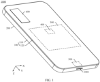
- FIG. 1 is a schematic diagram of a structure of an electronic device 1000 according to an embodiment of this application.
- the electronic device 1000 may be an electronic product such as a mobile phone, a tablet computer, a notebook computer, an infotainment system, a smartwatch, a smart band, or a POS machine (point of sales terminal, point of sales terminal).
- a width direction of the electronic device 1000 is defined as an X-axis direction
- a length direction of the electronic device 1000 is defined as a Y-axis direction
- a thickness direction of the electronic device 1000 is defined as a Z-axis direction
- the X-axis direction, the Y-axis direction, and the Z-axis direction are perpendicular to each other.
- the electronic device 1000 includes a housing 100, a display module 200, a circuit board 300, a processor 400, a speaker module 500, and a camera module 600.
- the housing 100 is provided with a speaker hole 1001, and the speaker hole 1001 is in communication with an inner side and an outer side of the housing 100.
- the display module 200 is mounted in the housing 100.
- the circuit board 300, the processor 400, and the speaker module 500 are all mounted on the inner side of the housing 100.
- the processor 400 is mounted on the circuit board 300, and is electrically connected to the circuit board 300.
- the circuit board 300 may be a main board (main board) of the electronic device 1000, and the processor 400 may be a CPU (central processing unit, central processing unit) of the electronic device 1000.
- the speaker module 500 is electrically connected to the processor 400, and is configured to receive an audio signal sent by the processor 400, and vibrate to produce sound based on the audio signal, so that the sound is diffused into an external environment through the speaker hole 1001, to implement sound production of the electronic device 1000.
- the camera module 600 is mounted in the housing 100, and is exposed relative to the housing 100.
- the camera module 600 is electrically connected to the processor 400, and is configured to receive an information collection signal sent by the processor 400, collect light outside the electronic device 1000, and form corresponding image data.
- FIG. 2 is a schematic diagram of a structure of a back cover 120 in the electronic device 1000 shown in FIG. 1 .
- the housing 100 includes a frame 110 and the back cover 120.
- the back cover 120 is mounted on one side of the frame 110.
- the frame 110 is provided with the speaker hole 1001.
- the back cover 120 may be a battery cover of the electronic device 1000.
- the back cover 120 is provided with a camera hole 1201, and the camera hole 1201 penetrates through the back cover 120 along a thickness direction of the back cover 120.
- the back cover 120 is mounted on one side of the frame 110.
- the camera hole 1201 is in communication with the inner side and outer side of the housing 100.
- the back cover 120 may be mounted in the frame 110 in a detachable manner, to facilitate maintenance and replacement of an internal component or module of the electronic device 1000.
- the display module 200 is mounted on the other side of the frame 110. That is, the display module 200 is mounted on a side that is of the frame 110 and that is away from the back cover 120. That is, the display module 200 and the back cover 120 are mounted on opposite sides of the frame 110 respectively.
- a display may be a display such as an LCD (liquid crystal display, liquid crystal display) or an OLED (organic light-emitting diode, organic light-emitting diode), and is configured to display information such as an image or a text.
- the camera module 600 is exposed relative to the back cover 120, to serve as a rear camera module of the electronic device 1000. Specifically, the camera module 600 passes through the camera hole 1201 of the back cover 120. A part of the camera module 600 is located on the inner side of the housing 100, a part of the camera module 600 is located in the camera hole 1201, and a part of the camera module 600 protrudes relative to the back cover 120. It should be noted that the exposure of the camera module 600 relative to the back cover 120 indicates that the back cover 120 does not completely cover the camera module 600. In some other embodiments, the camera module 600 may not protrude relative to the back cover 120.
- the camera module 600 may not pass through the camera hole 1201 of the back cover 120, a part of the camera module 600 is located on the inner side of the housing 100, and a part of the camera module 600 is located on the camera hole 1201, or the entire camera module 600 is accommodated on the inner side of the housing 100.
- the back cover is usually made of a glass fiber board, to improve strength of the back cover and ensure reliability of use of the back cover.
- the glass fiber board is formed by stacking and hot pressing a plurality of glass fiber layers (also referred to as a fiberglass layer).
- the plurality of glass fiber layers are directly stacked without staggering, and an inter-layer binding force between the plurality of glass fiber layers is poor.
- the puncture force can only be diffused along orthogonal directions of glass fibers (fiberglass) in the glass fiber layers.
- a puncture value of an existing glass fiber board formed by stacking four glass fiber layers is about 70 N.
- FIG. 3 is a schematic diagram of a cross-sectional structure of the back cover 120 shown in FIG. 2 cut along I-I.
- "Cut along I-I” means cutting along a plane on which the I-I line is located.
- the back cover 120 includes a glass fiber board 121 and a decorative layer 122.
- the decorative layer 122 is disposed on a bottom surface of the glass fiber board 121.
- a surface of the decorative layer 122 (that is, a bottom surface of the decorative layer 122), that faces away from the glass fiber board 121, is an appearance surface of the back cover 120.
- the decorative layer 122 may include an ink layer or a texture layer.
- the decorative layer 122 is configured to decorate the appearance of the back cover 120, to improve appearance refinement of the back cover 120.
- orientation words such as “top” and “bottom” in this application are described with reference to orientations shown in the accompanying drawings. Using a positive direction toward the Z-axis as the “bottom” and a negative direction toward the Z-axis as the “top” does not indicate or imply that a referred apparatus or component must have a specific orientation or be constructed and operated in a specific orientation, and should not be understood as a limitation on this application.
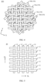
- FIG. 4 is a schematic diagram of a plane structure of a glass fiber board 121 in the back cover 120 shown in FIG. 3 in a first implementation.
- FIG. 5 is a schematic diagram of a plane structure of a glass fiber layer 10 in the glass fiber board 121 shown in FIG. 4 .
- the plane structure shown in FIG. 4 is a partially enlarged view of the plane structure of the glass fiber board 121.
- the glass fiber board 121 includes a plurality to glass fiber layers 10, and the plurality of glass fiber layers 10 are disposed in a stacking manner.
- a plurality of layers refer to two or more layers.
- Each glass fiber layer 10 includes a plurality of first fibers 11 and a plurality of second fibers 12, and the plurality of first fibers 11 and the plurality of second fibers 12 are disposed in an interlacing manner.
- the plurality of first fibers 11 and the plurality of second fibers 12 may form the glass fiber layer 10 through a weaving process. Both the first fibers 11 and the second fibers 12 are glass fibers.
- grammage of each glass fiber layer 10 is greater than or equal to 100 g/m 2 . In some other embodiments, the grammage of each glass fiber layer 10 may alternatively be less than 100 g/m 2 .
- glass fiber layers 10 described in this embodiment of this application are all glass fiber layers on which a resin impregnation process is performed, and a resin type and a resin content that are used in the resin impregnation process are not specifically limited in this application.
- Each glass fiber layer 10 has a first direction D 1 and a second direction D 2 .
- the plurality of first fibers 11 extend along the first direction D 1 and are arranged at intervals with each other along the second direction D 2 .
- the plurality of second fibers 12 extend along the second direction D 2 and are arranged at intervals with each other along the first direction D 1 .
- the first direction D 1 and the second direction D 2 are perpendicular to each other. In some other embodiments, the first direction D 1 and the second direction D 2 may not be perpendicular to each other.
- qualifiers such as parallel and perpendicular for a relative position relationship in this embodiment of this application are all for a current process level, and are not absolutely strict definitions in the mathematical sense, a slight deviation is allowed, and approximately perpendicular is acceptable.
- a is perpendicular to B means that A is perpendicular to B or approximately perpendicular to B, and an included angle between A and B is between 80 degrees and 100 degrees.
- a is parallel to B means thatAis parallel to B or approximately parallel to B, and an included angle between A and B is between 0 degrees and 10 degrees.
- a helical staggering angle is formed between any two glass fiber layers 10. It should be noted that a helical staggering angle between two glass fiber layers 10 is an included angle between the first directions D 1 of the two glass fiber layers 10, or an included angle between the second directions D 2 of the two glass fiber layers 10. A helical staggering angle between at least two glass fiber layers 10 is greater than 0 degrees and less than 90 degrees or is greater than 90 degrees and less than 180 degrees. In other words, at least two glass fiber layers 10 in the glass fiber board 121 are helically stacked in a staggering manner.
- the helical staggering angle between any two glass fiber layers 10 is greater than 0 degrees and less than 180 degrees.
- the plurality of glass fiber layers 10 are helically stacked in a staggering manner.
- a helical staggering angle between two adjacent glass fiber layers 10 is greater than 0 degrees and less than or equal to 45 degrees.
- the helical staggering angle between any two glass fiber layers 10 may be greater than 0 degrees and less than 90 degrees, or the helical staggering angle between any two glass fiber layers 10 may be greater than 0 degrees and less than or equal to 45 degrees.
- the four glass fiber layers 10 are respectively a first glass fiber layer 10a, a second glass fiber layer 10b, a third glass fiber layer 10c, and a fourth glass fiber layer 10d.
- the second glass fiber layer 10b, the third glass fiber layer 10c, and the fourth glass fiber layer 10d are sequentially laminated on a surface of the first glass fiber layer 10a.
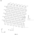
- FIG. 6 is a schematic diagram of a plane structure of the first glass fiber layer 10a in the glass fiber board 121 shown in FIG. 4 .
- FIG. 7 is a schematic diagram of a plane structure of the second glass fiber layer 10b in the glass fiber board 121 shown in FIG. 4 .
- FIG. 8 is a schematic diagram of a plane structure of the third glass fiber layer 10c in the glass fiber board 121 shown in FIG. 4 .
- FIG. 9 is a schematic diagram of a plane structure of the fourth glass fiber layer 10d in the glass fiber board 121 shown in FIG. 4 .
- an included angle between the first direction D 1 and an X-axis direction is ⁇
- an included angle between the second direction D 2 and a Y-axis direction is ⁇ . That is, in the first glass fiber layer 10a, an included angle between the first fiber 11 and the X-axis direction is ⁇ , and an included angle between the second fiber 12 and the Y-axis direction is ⁇ .
- the first direction D 1 is parallel to the X-axis direction
- the second direction D 2 is parallel to the Y-axis direction. That is, when each glass fiber layer 10 is not stacked, the included angle between the first fiber 11 and the X-axis direction is 0 degrees, and the included angle between the second fiber 12 and the Y-axis direction is 0 degrees.
- the first direction D 1 may not be parallel to the X-axis direction
- the second direction D 2 may not be parallel to the Y-axis direction.
- the first glass fiber layer 10a when the first glass fiber layer 10a is stacked, the first glass fiber layer 10a may first be rotated by ⁇ degrees in a counterclockwise direction, and then the first glass fiber layer 10a is stacked.
- the included angle between the first direction D 1 and the X-axis direction is ⁇
- the included angle between the second direction D 2 and the Y-axis direction is ⁇ . That is, in the second glass fiber layer 10b, the included angle between the first fiber 11 and the X-axis direction is ⁇ , and the included angle between the second fiber 12 and the Y-axis direction is ⁇ .
- a helical staggering angle between the first glass fiber layer 10a and the second glass fiber layer 10b is ⁇ - ⁇ .
- the second glass fiber layer 10b when the second glass fiber layer 10b is stacked on the surface of the first glass fiber layer 10a, the second glass fiber layer 10b may first be rotated by ⁇ degrees in the counterclockwise direction, and then the second glass fiber layer 10b is stacked on the surface of the first glass fiber layer 10a, so that the helical staggering angle between the first glass fiber layer 10a and the second glass fiber layer 10b is ⁇ - ⁇ .
- the included angle between the first direction D 1 and the X-axis direction is ⁇
- the included angle between the second direction D 2 and the Y-axis direction is ⁇ . That is, in the third glass fiber layer 10c, the included angle between the first fiber 11 and the X-axis direction is ⁇ , and the included angle between the second fiber 12 and the Y-axis direction is ⁇ .
- a helical staggering angle between the second glass fiber layer 10b and the third glass fiber layer 10c is ⁇ - ⁇ .
- the third glass fiber layer 10c when the third glass fiber layer 10c is stacked on a surface that is of the second glass fiber layer 10b and that faces away from the first glass fiber layer 10a, the third glass fiber layer 10c may first be rotated by ⁇ degrees in the counterclockwise direction, and then the third glass fiber layer 10c is stacked on the surface that is of the second glass fiber layer 10b and that faces away from the first glass fiber layer 10a, so that the helical staggering angle between the third glass fiber layer 10c and the second glass fiber layer 10b is ⁇ - ⁇ .
- the included angle between the first direction D 1 and the X-axis direction is ⁇
- the included angle between the second direction D 2 and the Y-axis direction is ⁇ . That is, in the fourth glass fiber layer 10d, the included angle between the first fiber 11 and the X-axis direction is ⁇ , and the included angle between the second fiber 12 and the Y-axis direction is ⁇ .
- a helical staggering angle between the third glass fiber layer 10c and the fourth glass fiber layer 10d is ⁇ - ⁇ .
- a helical staggering angle between adjacent glass fiber layers 10 is greater than 0 degrees and less than or equal to 45 degrees, so that the first fibers 11 and the second fibers 12 in the plurality of glass fiber layers 10 are radiated in a plurality of directions, thereby improving a stress dispersion effect of the glass fiber board 121.
- the helical staggering angle between adjacent glass fiber layers 10 is 20 degrees.
- the helical staggering angle between the second glass fiber layer 10b and the first glass fiber layer 10a, the helical staggering angle between the third glass fiber layer 10c and the second glass fiber layer 10b, and the helical staggering angle between the fourth glass fiber layer 10d and the third glass fiber layer 10c are all 20 degrees.
- a helical staggering angle between the third glass fiber layer 10c and the first glass fiber layer 10a is 40 degrees
- a helical staggering angle between the fourth glass fiber layer 10d and the first glass fiber layer 10a is 60 degrees
- a helical staggering angle between the fourth glass fiber layer 10d and the second glass fiber layer 10b is 40 degrees.
- FIG. 10 is a diagram of force analysis of the glass fiber board 121 shown in FIG. 4 .
- a dashed line with an arrow shown in FIG. 9 is a transmission direction of a puncture force F.
- the helical staggering angle between two adjacent glass fiber layers 10 is greater than 0 degrees and is less than or equal to 45 degrees
- the plurality of glass fiber layers 10 are helically stacked in a staggering manner
- the first fibers 11 and the second fibers 12 of the plurality of glass fiber layers 10 are disposed in a staggering manner in a star shape. That is, in the plurality of glass fiber layers 10, the first fibers 11 do not extend along the X-axis direction, and the second fibers 12 do not extend along the Y-axis direction.
- the plurality of glass fiber layers 10 are helically stacked in a staggering manner, thereby increasing an inter-layer binding force between the plurality of glass fiber layers 10.
- the puncture force F may be transmitted along a plurality of directions, so that a force area of the glass fiber board 121 is increased, a stress dispersion effect of the glass fiber board 121 is enhanced, and a synergistic toughening capability inside the glass fiber board 121 is increased, thereby improving puncture resistance of the glass fiber board 121, and helping implement a lightweight design of the electronic device 1000.
- a puncture value of the glass fiber board 121 is between 80 N and 85 N. Compared with the existing glass fiber board, the puncture resistance of the glass fiber board 121 shown in this implementation may be improved by at least 14%.
- FIG. 11 is a schematic diagram of a structure of the glass fiber board 121 shown in FIG. 3 in a second implementation.
- FIG. 12 is a schematic diagram of a plane structure of a glass fiber layer 10 in the glass fiber board 121 shown in FIG. 11 .
- the structure shown in FIG. 11 is a partially enlarged view of a structure of the glass fiber board 121.
- a difference between the glass fiber board 121 shown in this implementation and the glass fiber board 121 shown in the first implementation described above is that a helical staggering angle between any two glass fiber layers 10 is 0 degrees. In other words, a plurality of glass fiber layers 10 of the glass fiber board 121 are directly stacked without staggering. It should be noted that FIG. 11 shows only four glass fiber layers 10 of the glass fiber board 121, which does not form a limitation on an actual quantity of the glass fiber layers 10 in the glass fiber board 121.
- a first direction D 1 is parallel to an X-axis direction
- a second direction D 2 is parallel to a Y-axis direction. That is, in each glass fiber layer 10, an included angle between a first fiber 11 and the X-axis direction is 0 degrees, and an included angle between a second fiber 12 and the Y-axis direction is 0 degrees.
- the first direction D 1 may not be parallel to the X-axis direction
- the second direction D 2 may not be parallel to the Y-axis direction.
- the plurality of glass fiber layers 10 include one or more composite glass fiber layers. Specifically, the plurality of glass fiber layers 10 are all composite glass fiber layers. In each composite glass fiber layer 10, a plurality of first fibers 11 are all glass fibers. A plurality of second fibers 12 include a plurality of third fibers 13 and a plurality of fourth fibers 14. The plurality of fourth fibers 14 are all glass fibers. Toughness of the third fiber 13 is greater than toughness of the glass fiber, and strength of the third fiber 13 is greater than strength of the glass fiber.
- the third fiber 13 is an aramid fiber or a carbon fiber.
- the plurality of third fibers 13 are arranged at uniform intervals along the first direction D 1 , to ensure uniformity of toughness and strength of the glass fiber layer 10, and ensure uniformity of puncture resistance of the glass fiber layer 10, thereby ensuring uniformity of puncture resistance of the glass fiber board 121.
- the plurality of third fibers 13 and the plurality of fourth fibers 14 are arranged alternately along the first direction D 1 .
- the plurality of third fibers 13 may alternatively be arranged at non-uniform intervals along the first direction D 1 , or the plurality of second fibers 12 may alternatively include only one third fiber 13.
- the plurality of first fibers 11 may alternatively include a plurality of fifth fibers and one or more sixth fibers.
- the sixth fiber is a glass fiber. Toughness of the fifth fiber is greater than the toughness of the glass fiber, and strength of the fifth fiber is greater than the strength of the glass fiber.
- the sixth fiber is an aramid fiber or a carbon fiber.
- the plurality of fifth fibers are arranged at uniform intervals along the second direction D 2 .
- the plurality of first fibers 11 may include one fifth fiber, or the plurality of first fibers 11 may be all fifth fibers.
- the plurality of second fibers 12 of the glass fiber layer 10 are partially replaced with third fibers 13 with better toughness and strength, so that strength and toughness of the glass fiber layer 10 can be improved, thereby improving strength and toughness of the glass fiber board 121, and improving the puncture resistance of the glass fiber board 121.
- a puncture value of the glass fiber board 121 is between 80 N and 100 N.
- the puncture resistance of the glass fiber board 121 shown in this implementation may be improved by at least 14%.
- the plurality of glass fiber layers 10 may include one composite glass fiber layer, or the plurality of glass fiber layers 10 include a plurality of composite glass fiber layers and one or more common glass fiber layers.
- the plurality of first fibers 11 and the plurality of second fibers 12 are all glass fibers, and the plurality of composite glass fiber layers are uniformly arranged along a thickness direction of the glass fiber board 121, to ensure uniformity of toughness and strength of the glass fiber board 121, and ensure uniformity of puncture resistance of the glass fiber board 121.
- the plurality of composite glass fiber layers may be non-uniformly arranged along the thickness direction of the glass fiber board 121.
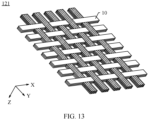
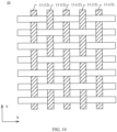
- FIG. 13 is a schematic diagram of a structure of the glass fiber board 121 shown in FIG. 3 in a third implementation.
- FIG. 14 is a schematic diagram of a plane structure of the glass fiber layer 10 in the glass fiber board 121 shown in FIG. 13 .
- the structure shown in FIG. 13 is a partially enlarged view of a structure of the glass fiber board 121.
- FIG. 15 is a schematic diagram of a plane structure of the glass fiber board 121 shown in FIG. 3 in a fourth implementation.
- the plane structure shown in FIG. 15 is a partially enlarged view of the plane structure of the glass fiber board 121.
- a difference between the glass fiber board 121 shown in this implementation and the glass fiber board 121 shown in the second implementation described above is that a helical staggering angle between at least two glass fiber layers 10 is greater than 0 degrees and less than 90 degrees, or is greater than 90 degrees and less than 180 degrees.
- at least two glass fiber layers 10 in the glass fiber board 121 are helically stacked in a staggering manner.
- For a structure of a helical staggering angle between two glass fiber layers 10 in the glass fiber board 121 reference may be made to related descriptions of the first implementation described above, and details are not described herein again.
- the plurality of second fibers 12 of the glass fiber layer 10 are partially replaced with third fibers 13 with better toughness and strength, so that strength and toughness of the glass fiber layer 10 can be improved, thereby improving strength and toughness of the glass fiber board 121, and improving the puncture resistance of the glass fiber board 121.
- at least two glass fiber layers 10 are helically stacked in a staggering manner, and the first fibers 11 and the second fibers 12 of the at least two glass fiber layers 10 are disposed in a staggering manner in a star shape, thereby increasing an inter-layer binding force between the plurality of glass fiber layers 10.
- the puncture force F may be transmitted along extending directions of the first fibers 11 and the second fibers 12 of the plurality of glass fiber layers 10. Because the at least two the glass fiber layers 10 are helically stacked in a staggering manner, the puncture force F may not only be transmitted along an X-axis direction and a Y-axis direction, but also be transmitted along another direction.
- the puncture force F may be transmitted along a plurality of directions, so that a force area of the glass fiber board 121 is increased, a stress dispersion effect of the glass fiber board 121 is enhanced, and a synergistic toughening capability inside the glass fiber board 121 is increased, thereby improving the puncture resistance of the glass fiber board 121.
- a puncture value of the glass fiber board 121 is between 100 N and 120 N. Compared with the existing glass fiber board, the puncture resistance of the glass fiber board 121 shown in this implementation may be improved by at least 21%.
- the glass fiber board 121 of the back cover 120 has good puncture resistance. Therefore, the back cover 120 also has good puncture resistance.
- the back cover 120 shown in this application is made of the glass fiber board 121, which helps improve strength of the back cover 120, ensures reliability of use of the back cover 120, and further ensures reliability of use of the electronic device 1000.
- FIG. 16 is a process flowchart of a first preparation method for a glass fiber board according to an embodiment of this application.
- the preparation method for a glass fiber board in this embodiment is used for preparing the glass fiber board 121 shown in the first implementation described above.
- the preparation method for a glass fiber board includes step S1 to step S3.
- Step S1 Provide a plurality of glass fiber layers 10.
- each glass fiber layer 10 includes a plurality of first fibers 11 and a plurality of second fibers 12.
- the plurality of first fibers 11 and the plurality of second fibers 12 form the glass fiber layer 10 through a weaving process.
- Both the first fibers 11 and the second fibers 12 are glass fibers.
- grammage of the glass fiber layer 10 is greater than or equal to 100 g/m 2 . In some other embodiments, the grammage of the glass fiber layer 10 may alternatively be less than 100 g/m 2 .
- Each glass fiber layer 10 has a first direction D 1 and a second direction D 2 .
- the plurality of first fibers 11 extend along the first direction D 1 and are arranged at intervals with each other along the second direction D 2 .
- the plurality of second fibers 12 extend along the second direction D 2 and are arranged at intervals with each other along the first direction D 1 .
- the first direction D 1 and the second direction D 2 are perpendicular to each other. In some other embodiments, the first direction D 1 and the second direction D 2 may not be perpendicular to each other.
- glass fiber layers 10 described in this embodiment of this application are all glass fiber layers on which a resin impregnation process is performed.
- a resin system and a resin content that are used in the resin impregnation process are not specifically limited in this embodiment of this application.
- Step S2 Stack the plurality of glass fiber layers 10. Specifically, at least two glass fiber layers 10 are helically stacked in a staggering manner.
- a helical staggering angle between at least two types of glass fiber layers 10 is greater than 0 degrees and less than 90 degrees, or is greater than 90 degrees and less than 180 degrees.
- a helical staggering angle between any two glass fiber layers 10 is greater than 0 degrees and less than 180 degrees.
- a helical staggering angle between two adjacent glass fiber layers 10 is greater than 0 degrees and less than or equal to 45 degrees.
- the helical staggering angle between any two glass fiber layers 10 may be greater than 0 degrees and less than 90 degrees, or the helical staggering angle between any two glass fiber layers 10 may be greater than 0 degrees and less than or equal to 45 degrees.
- the plurality of glass fiber layers 10 include the first glass fiber layer 10a (as shown in FIG. 6 ), the second glass fiber layer 10b (as shown in FIG. 7 ), the third glass fiber layer 10c (as shown in FIG. 8 ), and the fourth glass fiber layer 10d (as shown in FIG. 9 ).
- the helical staggering angle between the second glass fiber layer 10b and the first glass fiber layer 10a is ⁇ - ⁇
- the helical staggering angle between the third glass fiber layer 10c and the second glass fiber layer 10b is ⁇ - ⁇
- the helical staggering angle between the fourth glass fiber layer 10d and the third glass fiber layer 10c is ⁇ - ⁇ .
- the helical staggering angle between adjacent glass fiber layers 10 is 20 degrees.
- the first glass fiber layer 10a is rotated by 20 degrees
- the second glass fiber layer 10b is rotated by 40 degrees
- the third glass fiber layer 10c is rotated by 60 degrees
- the fourth glass fiber layer 10d is rotated by 80 degrees
- the first glass fiber layer 10a, the second glass fiber layer 10b, the third glass fiber layer 10c, and the fourth glass fiber layer 10d are sequentially stacked.
- the helical staggering angle between adjacent glass fiber layers 10 may alternatively be 30 degrees.
- the first glass fiber layer 10a may be rotated by 30 degrees
- the second glass fiber layer 10b may be rotated by 60 degrees
- the third glass fiber layer 10c may be rotated by 90 degrees
- the fourth glass fiber layer 10d may be rotated by 120 degrees
- the first glass fiber layer 10a may be rotated by 45 degrees
- the second glass fiber layer 10b may be rotated by 90 degrees
- the third glass fiber layer 10c may be rotated by 135 degrees
- the fourth glass fiber layer 10d may be rotated by 180 degrees, and subsequently, the first glass fiber layer 10a, the second glass fiber layer 10b, the third glass fiber layer 10c, and the fourth glass fiber layer 10d are sequentially stacked.
- Step S3 Laminate the plurality of stacked glass fiber layers 10, to obtain the glass fiber board 121, as shown in FIG. 4 .
- the plurality of stacked glass fiber layers 10 are laminated by using a vacuum hot pressing tank process, to obtain the glass fiber board 121.
- a heat pressing temperature is about 120 degrees Celsius
- a pressure is 1 MPa
- a curing time is between 60 minutes and 90 minutes.
- An embodiment of this application further provides a second preparation method for a glass fiber board.
- the second preparation method for a glass fiber board is used for preparing the glass fiber board 121 shown in the second implementation described above.
- the preparation method for a glass fiber board in this embodiment includes step S1 to step S3.
- Step S1 Provide a plurality of glass fiber layers 10.
- each glass fiber layer 10 includes a plurality of first fibers 11 and a plurality of second fibers 12.
- the plurality of first fibers 11 and the plurality of second fibers 12 form the glass fiber layer 10 through a weaving process.
- Each glass fiber layer 10 has a first direction D 1 and a second direction D 2 .
- the first direction D 1 is parallel to an X-axis direction
- the second direction D 2 is parallel to a Y-axis direction.
- the plurality of first fibers 11 extend along the first direction D 1 and are arranged at intervals with each other along the second direction D 2 .
- the plurality of glass fiber layers 10 include one or more composite glass fiber layers. Specifically, the plurality of glass fiber layers 10 are all composite glass fiber layers. In each composite glass fiber layer 10, the plurality of first fibers 11 are all glass fibers.
- the plurality of second fibers 12 include a plurality of third fibers 13 and a plurality of fourth fibers 14. The plurality of fourth fibers 14 are all glass fibers. Toughness of the third fiber 13 is greater than toughness of the glass fiber, and strength of the third fiber 13 is greater than strength of the glass fiber.
- the third fiber 13 is an aramid fiber or a carbon fiber.
- the plurality of third fibers 13 are arranged at uniform intervals along the first direction D 1 , to ensure uniformity of toughness and strength of the glass fiber layer 10, and ensure uniformity of puncture resistance of the glass fiber layer 10, thereby ensuring uniformity of puncture resistance of the glass fiber board 121.
- the plurality of third fibers 13 and the plurality of fourth fibers 14 are arranged alternately along the first direction D 1 .
- the plurality of third fibers 13 may alternatively be arranged at non-uniform intervals along the first direction D 1 , or the plurality of second fibers 12 may alternatively include only one third fiber 13, or the plurality of second fibers 12 may be all fourth fibers 14.
- the plurality of first fibers 11 may alternatively include a plurality of fifth fibers and one or more sixth fibers.
- the sixth fiber is a glass fiber. Toughness of the fifth fiber is greater than the toughness of the glass fiber, and strength of the fifth fiber is greater than the strength of the glass fiber.
- the sixth fiber is an aramid fiber or a carbon fiber.
- the plurality of fifth fibers are arranged at uniform intervals along the second direction D 2 .
- the plurality of first fibers 11 may include one fifth fiber, or the plurality of first fibers 11 may be all fifth fibers.
- step S1 includes step S11 to step S13.
- Step S11 Provide a fiber cloth.
- the fiber cloth includes a plurality of radial fibers and a plurality of zonal fibers.
- the plurality of zonal fibers and the plurality of radial fibers form the fiber cloth through a weaving process.
- the plurality of zonal fibers are all glass fibers.
- the plurality of radial fibers includes a plurality of first-type fibers and a plurality of second-type fibers.
- the plurality of second-type fibers are all glass fibers. Toughness and strength of the first-type fiber are both greater than those of the second-type fiber.
- the first-type fiber is an aramid fiber or a carbon fiber. It should be noted that the thicknesses of the glass fiber, the aramid fiber, and the carbon fiber in the fiber cloth shown in this embodiment of this application are not specifically limited, and the fiber cloth may only be formed through the weaving process.
- Step S12 Perform resin impregnation processing on the fiber cloth.
- the fiber cloth is impregnated with epoxy resin.
- a resin content is about 50%, and the thickness of the impregnated fiber cloth is about 0.1 mm.
- another type of resin may be used to impregnate the fiber cloth, and/or resin of another content may be used to impregnate the fiber cloth.
- a resin type, a resin content, and the thickness of the fiber cloth are not specifically limited in this embodiment of this application.
- Step S13 Dry and wrap the impregnated fiber cloth, and then cut the impregnated fiber cloth into a plurality of glass fiber layers 10.
- the plurality of zonal fibers of the fiber cloth form the plurality of first fibers 11 of the glass fiber layer 10
- the plurality of radial fibers of the fiber cloth form the plurality of second fibers 12 of the glass fiber layer 10.
- the plurality of first-type fibers of the fiber cloth form the plurality of third fibers 13 of the glass fiber layer 10
- the plurality of second-type fibers of the fiber cloth form the plurality of fourth fibers of the glass fiber layer 10.
- Step S2 Stack the plurality of glass fiber layers 10. Specifically, the plurality of glass fiber layers 10 are directly stacked. A helical staggering angle between any two glass fiber layers 10 is 0 degrees.
- Step S3 Laminate the plurality of stacked glass fiber layers 10, to obtain the glass fiber board 121, as shown in FIG. 11 .
- the plurality of stacked glass fiber layers 10 are laminated by using a vacuum hot pressing tank process, to obtain the glass fiber board 121.
- a heat pressing temperature is about 120 degrees Celsius
- a pressure is 1 MPa
- a curing time is between 60 minutes and 90 minutes.
- An embodiment of this application further provides a third preparation method for a glass fiber board.
- the third preparation method for a glass fiber board is used for preparing the glass fiber board 121 shown in the fourth implementation described above.
- the preparation method for a glass fiber board in this embodiment includes step S1 to step S3.
- Step S1 Provide a plurality of glass fiber layers 10. It should be noted that step S1 in this embodiment is the same as step S1 in the second preparation method for a glass fiber board, and details are not described herein again.
- Step S2 Stack the plurality of glass fiber layers 10. Specifically, at least two glass fiber layers 10 are helically stacked in a staggering manner.
- a helical staggering angle between at least two types of glass fiber layers 10 is greater than 0 degrees and less than 90 degrees, or is greater than 90 degrees and less than 180 degrees.
- a helical staggering angle between any two glass fiber layers 10 is greater than 0 degrees and less than 180 degrees.
- a helical staggering angle between two adjacent glass fiber layers 10 is greater than 0 degrees and less than or equal to 45 degrees.
- step S2 in this embodiment is the same as step S2 in the first preparation method for a glass fiber board, and details are not described herein again.
- Step S3 Laminate the plurality of stacked glass fiber layers 10, to obtain the glass fiber board 121, as shown in FIG. 15 .
- the plurality of stacked glass fiber layers 10 are laminated by using a vacuum hot pressing tank process, to obtain the glass fiber board 121.
- a heat pressing temperature is about 120 degrees Celsius
- a pressure is 1 MPa
- a curing time is between 60 minutes and 90 minutes.
Landscapes
- Engineering & Computer Science (AREA)
- Textile Engineering (AREA)
- Chemical & Material Sciences (AREA)
- Composite Materials (AREA)
- Mechanical Engineering (AREA)
- Microelectronics & Electronic Packaging (AREA)
- Signal Processing (AREA)
- Physics & Mathematics (AREA)
- Fluid Mechanics (AREA)
- Laminated Bodies (AREA)
Abstract
Description
- This application claims priority to
Chinese Patent Application No. 202210905853.4, filed with the China National Intellectual Property Administration on July 29, 2022 - This application relates to the field of electronic device technologies, and in particular, to a glass fiber board, a back cover, an electronic device, and a preparation method for a glass fiber board.
- With continuous development of science and technology, electronic devices such as mobile phones are widely used in people's daily life and work, and have become indispensable daily articles. In a current electronic device, a glass fiber board (also referred to as a fiberglass board) is usually used to prepare a back cover to implement a lightweight design of the electronic device. However, the glass fiber board has poor puncture resistance, which reduces reliability of use of the electronic device.
- This application provides a glass fiber board, a back cover, an electronic device, and a preparation method for a glass fiber board, to improve puncture resistance of the glass fiber board and improve reliability of use of the electronic device.
- According to a first aspect, this application provides a glass fiber board, including a plurality of glass fiber layers, and the plurality of glass fiber layers are disposed in a stacking manner. Each glass fiber layer includes a plurality of first fibers and a plurality of second fibers, and the plurality of first fibers and the plurality of second fibers are disposed in an interlacing manner. Each glass fiber layer has a first direction and a second direction. The plurality of first fibers extend along the first direction of the glass fiber layer and are arranged at intervals along the second direction of the glass fiber layer. The plurality of second fibers extend along the first direction of the glass fiber layer and are arranged at intervals along the first direction of the glass fiber layer.
- A helical staggering angle is formed between any two glass fiber layers. A helical staggering angle between two glass fiber layers is an included angle between the first directions of the two glass fiber layers, or a helical staggering angle between two glass fiber layers is an included angle between the second directions of the two glass fiber layers.
- A helical staggering angle between at least two glass fiber layers is greater than 0 degrees and less than 90 degrees or is greater than 90 degrees and less than 180 degrees. In other words, at least two glass fiber layers are helically stacked in a staggering manner.
- In the glass fiber board shown in this application, at least two glass fiber layers are helically stacked in a staggering manner, and the first fibers and the second fibers of the at least two glass fiber layers are disposed in a staggering manner in a star shape, thereby increasing an inter-layer binding force between the plurality of glass fiber layers. When the glass fiber board is subjected to a puncture force F, the puncture force F may be transmitted along extending directions of the first fibers and the second fibers of the plurality of glass fiber layers. Because at least two glass fiber layers are helically stacked in a staggering manner, the puncture force F may be transmitted along a plurality of directions, so that a force area of the glass fiber board is increased, a stress dispersion effect of the glass fiber board is enhanced, and a synergistic toughening capability inside the glass fiber board is increased, thereby improving puncture resistance of the glass fiber board.
- In an implementation, the first direction and the second direction of the glass fiber layer are perpendicular to each other.
- In an implementation, the glass fiber layer is formed by weaving the plurality of first fibers and the plurality of second fibers.
- In an implementation, the helical staggering angle between any two glass fiber layers is greater than 0 degrees and less than 180 degrees. In other words, the plurality of glass fiber layers are helically stacked in a staggering manner, and the first fibers and the second fibers of any two glass fiber layers are disposed in a staggering manner in a star shape, thereby increasing an inter-layer binding force between the plurality of glass fiber layers. When the glass fiber board is subjected to a puncture force F, the puncture force F may be transmitted along extending directions of the first fibers and the second fibers of the plurality of glass fiber layers. Because the plurality of glass fiber layers are helically stacked in a staggering manner, the puncture force F may be transmitted along a plurality of directions, so that a force area of the glass fiber board is increased, a stress dispersion effect of the glass fiber board is enhanced, and a synergistic toughening capability inside the glass fiber board is increased, thereby improving the puncture resistance of the glass fiber board.
- In an implementation, a helical staggering angle between any two glass fiber layers is greater than 0 degrees and less than 90 degrees, so that the first fibers and the second fibers in the plurality of glass fiber layers are radiated in a plurality of directions, which helps improve a stress dispersion effect of the glass fiber board, and further improves the puncture resistance of the glass fiber board.
- In an implementation, a helical staggering angle between any two glass fiber layers is greater than 0 degrees and less than or equal to 45 degrees, so that the first fibers and the second fibers in the plurality of glass fiber layers are radiated in a plurality of directions, which helps improve a stress dispersion effect of the glass fiber board, and further improves the puncture resistance of the glass fiber board.
- In an implementation, a helical staggering angle between two adjacent glass fiber layers is greater than 0 degrees and less than or equal to 45 degrees, so that the first fibers and the second fibers in the plurality of glass fiber layers are radiated in a plurality of directions, which helps improve a stress dispersion effect of the glass fiber board, and further improves the puncture resistance of the glass fiber board. For example, an included angle between two adjacent glass fiber layers is 20 degrees, 30 degrees, or 45 degrees.
- In an implementation, in each glass fiber layer, both the plurality of first fibers and the plurality of second fibers are glass fibers.
- In an implementation, the plurality of glass fiber layers include one or more composite glass fiber layers, the plurality of second fibers in each composite glass fiber layer include one or more third fibers, and toughness of the third fiber is greater than toughness of a glass fiber.
- In the composite glass fiber layer, the glass fibers are replaced with fibers of better toughness, so that toughness of the composite glass fiber layer can be improved, and puncture resistance of the composite glass fiber layer can be improved, thereby improving the puncture resistance of the glass fiber board.
- In an implementation, strength of the third fiber is greater than strength of the glass fiber.
- In the composite glass fiber layer, the glass fibers are replaced with fibers of better strength, so that strength of the composite glass fiber layer can be improved, and the puncture resistance of the composite glass fiber layer can be improved, thereby improving the puncture resistance of the glass fiber board.
- In an implementation, there are a plurality of third fibers, and the plurality of third fibers are arranged at uniform intervals along a first direction of the composite glass fiber layer, to ensure uniformity of the toughness and the strength of the composite glass fiber layer, and ensure uniformity of the puncture resistance of the composite glass fiber layer, thereby ensuring uniformity of the puncture resistance of the glass fiber board.
- In an implementation, the third fiber is an aramid fiber or a carbon fiber.
- In an implementation, the plurality of second fibers in each composite glass fiber layer further include one or more fourth fibers, and the fourth fiber is a glass fiber.
- In the composite glass fiber layer, some of the glass fibers are replaced with fibers of better toughness and strength, so that the toughness and the strength of the composite glass fiber layer can be improved, and the puncture resistance of the composite glass fiber layer can be improved, thereby improving the puncture resistance of the glass fiber board.
- In an implementation, there are a plurality of third fibers and a plurality of fourth fibers, and the plurality of third fibers and the plurality of fourth fibers are alternately arranged along the first direction of the composite glass fiber layer.
- In an implementation, each second fiber in each composite glass fiber layer is a third fiber.
- In the composite glass fiber layer, all the glass fibers are replaced with fibers of better toughness and strength, so that the toughness and the strength of the composite glass fiber layer can be improved, and the puncture resistance of the composite glass fiber layer can be improved, thereby improving the puncture resistance of the glass fiber board.
- In an implementation, the plurality of first fibers in each composite glass fiber layer are all glass fibers.
- In an implementation, the plurality of first fibers in each composite glass fiber layer include one or more fifth fibers, and toughness of the fifth fiber is greater than the toughness of the glass fiber.
- In the composite glass fiber layer, the glass fibers are replaced with fibers of better toughness, so that the toughness of the composite glass fiber layer can be improved, and the puncture resistance of the composite glass fiber layer can be improved, thereby improving the puncture resistance of the glass fiber board.
- In an implementation, strength of the fifth fiber is greater than the strength of the glass fiber.
- In the composite glass fiber layer, the glass fibers are replaced with fibers of better strength, so that the strength of the composite glass fiber layer can be improved, and the puncture resistance of the composite glass fiber layer can be improved, thereby improving the puncture resistance of the glass fiber board.
- In an implementation, there are a plurality of fifth fibers, and the plurality of fifth fibers are arranged at uniform intervals along a second direction of the composite glass fiber layer, to ensure the uniformity of the toughness and the strength of the composite glass fiber layer, and ensure the uniformity of the puncture resistance of the composite glass fiber layer, thereby ensuring the uniformity of the puncture resistance of the glass fiber board.
- In an implementation, the fifth fiber is an aramid fiber or a carbon fiber.
- In an implementation, the plurality of first fibers in each composite glass fiber layer further include one or more sixth fibers, and the sixth fiber is a glass fiber.
- In the composite glass fiber layer, some of the glass fibers are replaced with fibers of better toughness and strength, so that the toughness and the strength of the composite glass fiber layer can be improved, and the puncture resistance of the composite glass fiber layer can be improved, thereby improving the puncture resistance of the glass fiber board.
- In an implementation, each first fiber in each composite glass fiber layer is a fifth fiber.
- In the composite glass fiber layer, all the glass fibers are replaced with fibers of better toughness and strength, so that the toughness and the strength of the composite glass fiber layer can be improved, and the puncture resistance of the composite glass fiber layer can be improved, thereby improving the puncture resistance of the glass fiber board.
- In an implementation, there are a plurality of composite glass fiber layers, and the plurality of composite glass fiber layers are uniformly arranged along a thickness direction of the glass fiber layer, to ensure uniformity of toughness and strength of the glass fiber board, and ensure the uniformity of the puncture resistance of the glass fiber board.
- In an implementation, each glass fiber layer is a composite glass fiber layer.
- According to a second aspect, this application provides a glass fiber board, including a plurality of glass fiber layers that are disposed in a stacking manner, where each glass fiber layer includes a plurality of first fibers and a plurality of second fibers, each glass fiber layer has a first direction and a second direction, the plurality of first fibers extend along the first direction of the glass fiber layer and are arranged at intervals along the second direction of the glass fiber layer, and the plurality of second fibers extend along the first direction of the glass fiber layer and are arranged at intervals along the first direction of the glass fiber layer; and
the plurality of glass fiber layers include one or more composite glass fiber layers, the plurality of second fibers in each composite glass fiber layer include one or more third fibers, and toughness of the third fiber is greater than toughness of a glass fiber. - In the composite glass fiber layer of the glass fiber board shown in this application, glass fibers are replaced with fibers of better toughness, so that toughness of the composite glass fiber layer can be improved, and puncture resistance of the composite glass fiber layer can be improved, thereby improving puncture resistance of the glass fiber board.
- In an implementation, the first direction and the second direction are perpendicular to each other.
- In an implementation, the glass fiber layer is formed by weaving the plurality of first fibers and the plurality of second fibers.
- In an implementation, strength of the third fiber is greater than strength of the glass fiber.
- In the composite glass fiber layer, the glass fibers are replaced with fibers of better strength, so that strength of the composite glass fiber layer can be improved, and the puncture resistance of the composite glass fiber layer can be improved, thereby improving the puncture resistance of the glass fiber board.
- In an implementation, there are a plurality of third fibers, and the plurality of third fibers are arranged at uniform intervals along a first direction of the composite glass fiber layer, to ensure uniformity of the toughness and the strength of the composite glass fiber layer, and ensure uniformity of the puncture resistance of the composite glass fiber layer, thereby ensuring uniformity of the puncture resistance of the glass fiber board.
- In an implementation, the third fiber is an aramid fiber or a carbon fiber.
- In an implementation, the plurality of second fibers in each composite glass fiber layer further include one or more fourth fibers, and the fourth fiber is a glass fiber.
- In the composite glass fiber layer, some of the glass fibers are replaced with fibers of better toughness and strength, so that the toughness and the strength of the composite glass fiber layer can be improved, and the puncture resistance of the composite glass fiber layer can be improved, thereby improving the puncture resistance of the glass fiber board.
- In an implementation, there are a plurality of third fibers and a plurality of fourth fibers, and the plurality of third fibers and the plurality of fourth fibers are alternately arranged along the first direction of the composite glass fiber layer.
- In an implementation, each second fiber in each composite glass fiber layer is a third fiber.
- In the composite glass fiber layer, all the glass fibers are replaced with fibers of better toughness and strength, so that the toughness and the strength of the composite glass fiber layer can be improved, and the puncture resistance of the composite glass fiber layer can be improved, thereby improving the puncture resistance of the glass fiber board.
- In an implementation, the plurality of first fibers in each composite glass fiber layer are all glass fibers.
- In an implementation, the plurality of first fibers in each composite glass fiber layer include one or more fifth fibers, and toughness of the fifth fiber is greater than the toughness of the glass fiber.
- In the composite glass fiber layer, the glass fibers are replaced with fibers of better toughness, so that the toughness of the composite glass fiber layer can be improved, and the puncture resistance of the composite glass fiber layer can be improved, thereby improving the puncture resistance of the glass fiber board.
- In an implementation, strength of the fifth fiber is greater than the strength of the glass fiber.
- In the composite glass fiber layer, the glass fibers are replaced with fibers of better strength, so that strength of the composite glass fiber layer can be improved, and the puncture resistance of the composite glass fiber layer can be improved, thereby improving the puncture resistance of the glass fiber board.
- In an implementation, there are a plurality of fifth fibers, and the plurality of fifth fibers are arranged at uniform intervals along a second direction of the composite glass fiber layer, to ensure the uniformity of the toughness and the strength of the composite glass fiber layer, and ensure the uniformity of the puncture resistance of the composite glass fiber layer, thereby ensuring the uniformity of the puncture resistance of the glass fiber board.
- In an implementation, the fifth fiber is an aramid fiber or a carbon fiber.
- In an implementation, the plurality of first fibers in each composite glass fiber layer further include one or more sixth fibers, and the sixth fiber is a glass fiber.
- In the composite glass fiber layer, some of the glass fibers are replaced with fibers of better toughness and strength, so that the toughness and the strength of the composite glass fiber layer can be improved, and the puncture resistance of the composite glass fiber layer can be improved, thereby improving the puncture resistance of the glass fiber board.
- In an implementation, each first fiber in each composite glass fiber layer is a fifth fiber.
- In the composite glass fiber layer, all the glass fibers are replaced with fibers of better toughness and strength, so that the toughness and the strength of the composite glass fiber layer can be improved, and the puncture resistance of the composite glass fiber layer can be improved, thereby improving the puncture resistance of the glass fiber board.
- In an implementation, there are a plurality of composite glass fiber layers, and the plurality of composite glass fiber layers are uniformly arranged along a thickness direction of the glass fiber layer, to ensure uniformity of toughness and strength of the glass fiber board, and ensure the uniformity of the puncture resistance of the glass fiber board.
- In an implementation, each glass fiber layer is a composite glass fiber layer.
- In an implementation, a helical staggering angle of any two glass fiber layers is 0 degrees. In other words, the plurality of glass fiber layers are directly stacked without being helically stacked in a staggering manner.
- In an implementation, a helical staggering angle between at least two glass fiber layers is greater than 0 degrees and less than 90 degrees or is greater than 90 degrees and less than 180 degrees. In other words, at least two glass fiber layers are helically stacked in a staggering manner.
- In the glass fiber board shown in this application, at least two glass fiber layers are helically stacked in a staggering manner, and the first fibers and the second fibers of the at least two glass fiber layers are disposed in a staggering manner in a star shape, thereby increasing an inter-layer binding force between the plurality of glass fiber layers. When the glass fiber board is subjected to a puncture force F, the puncture force F may be transmitted along extending directions of the first fibers and the second fibers of the plurality of glass fiber layers. Because at least two glass fiber layers are helically stacked in a staggering manner, the puncture force F may be transmitted along a plurality of directions, so that a force area of the glass fiber board is increased, a stress dispersion effect of the glass fiber board is enhanced, and a synergistic toughening capability inside the glass fiber board is increased, thereby improving the puncture resistance of the glass fiber board.
- In an implementation, the helical staggering angle between any two glass fiber layers is greater than 0 degrees and less than 180 degrees. In other words, the plurality of glass fiber layers are helically stacked in a staggering manner, and the first fibers and the second fibers of any two glass fiber layers are disposed in a staggering manner in a star shape, thereby increasing an inter-layer binding force between the plurality of glass fiber layers. When the glass fiber board is subjected to a puncture force F, the puncture force F may be transmitted along extending directions of the first fibers and the second fibers of the plurality of glass fiber layers. Because the plurality of glass fiber layers are helically stacked in a staggering manner, the puncture force F may be transmitted along a plurality of directions, so that a force area of the glass fiber board is increased, a stress dispersion effect of the glass fiber board is enhanced, and a synergistic toughening capability inside the glass fiber board is increased, thereby improving the puncture resistance of the glass fiber board.
- In an implementation, the helical staggering angle between any two glass fiber layers is greater than 0 degrees and less than 90 degrees, so that the first fibers and the second fibers in the plurality of glass fiber layers are radiated in a plurality of directions, which helps improve a stress dispersion effect of the glass fiber board, and further improves the puncture resistance of the glass fiber board.
- In an implementation, the helical staggering angle between any two glass fiber layers is greater than 0 degrees and is less than or equal to 45 degrees, so that the first fibers and the second fibers in the plurality of glass fiber layers are radiated in a plurality of directions, which helps improve the stress dispersion effect of the glass fiber board, and further improves the puncture resistance of the glass fiber board.
- In an implementation, a helical staggering angle between two adjacent glass fiber layers is greater than 0 degrees and less than or equal to 45 degrees, to increase distribution density of the first fibers and the second fibers of the plurality of glass fiber layers in the plurality of directions, which helps improve the puncture resistance of the glass fiber board. For example, an included angle between two adjacent glass fiber layers is 20 degrees, 30 degrees, or 45 degrees.
- According to a third aspect, this application provides a back cover, including any glass fiber board described above and a decorative layer, where the decorative layer is disposed on a bottom surface of the glass fiber board. The glass fiber board shown in this application has good puncture resistance. Therefore, the back cover also has good puncture resistance. In addition, compared with a back cover made of plastic, the back cover shown in this application is made of the glass fiber board, which can improve strength of the back cover and ensure reliability of use of the back cover.
- According to a fourth aspect, this application provides an electronic device, including the back cover described above and a frame, where the back cover is mounted on one side of the frame.
- In the electronic device shown in this application, the glass fiber board of the back cover has good puncture resistance. Therefore, the back cover also has good puncture resistance. In addition, compared with a back cover made of plastic, the back cover of the electronic device shown in this application is made of the glass fiber board, which can improve the strength of the back cover, ensure the reliability of use of the back cover, and further ensure reliability of use of the electronic device.
- According to a fifth aspect, this application provides a preparation method for a glass fiber board, including:
- providing a plurality of glass fiber layers, where each glass fiber layer includes a plurality of first fibers and a plurality of second fibers, each glass fiber layer has a first direction and a second direction, the plurality of first fibers extend along the first direction of the glass fiber layer and are arranged at intervals along the second direction of the glass fiber layer, and the plurality of second fibers extend along the second direction of the glass fiber layer and are arranged at intervals along the first direction of the glass fiber layer;
- stacking the plurality of glass fiber layers, where a helical staggering angle between at least two glass fiber layers is greater than 0 degrees and less than 90 degrees or is greater than 90 degrees and less than 180 degrees; and
- laminating the plurality of stacked glass fiber layers, to obtain a glass fiber layer.
- In an implementation, in a process of stacking the plurality of glass fiber layers, a helical staggering angle between any two glass fiber layers is greater than 0 degrees and less than 180 degrees.
- In an implementation, in the process of stacking the plurality of glass fiber layers, the helical staggering angle between any two glass fiber layers is greater than 0 degrees and less than 90 degrees.
- In an implementation, in the process of stacking the plurality of glass fiber layers, the helical staggering angle between any two glass fiber layers is greater than 0 degrees and less than or equal to 45 degrees.
- In an implementation, in the process of stacking the plurality of glass fiber layers, a helical staggering angle between two adjacent glass fiber layers is greater than 0 degrees and less than or equal to 45 degrees.
- In an implementation, in a process of laminating the plurality of stacked glass fiber layers, the plurality of stacked glass fiber layers are laminated by using a vacuum hot pressing tank.
- In an implementation, in the process of laminating the plurality of stacked glass fiber layers, a hot pressing temperature is 120 degrees Celsius, a pressure is 1 MPa, and a curing time is between 60 min and 90 min.
- According to a sixth aspect, this application provides a preparation method for a glass fiber board, including:
- providing a plurality of glass fiber layers, where each glass fiber layer includes a plurality of first fibers and a plurality of second fibers, each glass fiber layer has a first direction and a second direction, the plurality of first fibers extend along the first direction of the glass fiber layer and are arranged at intervals along the second direction of the glass fiber layer, the plurality of second fibers extend along the first direction of the glass fiber layer and are arranged at intervals along the first direction of the glass fiber layer, the plurality of glass fiber layers include one or more composite glass fiber layers, the plurality of second fibers in each composite glass fiber layer include one or more third fibers, and toughness of the third fiber is greater than toughness of a glass fiber;
- stacking the plurality of glass fiber layers; and
- laminating the plurality of stacked glass fiber layers, to obtain a glass fiber layer.
- In an implementation, in a process of stacking the plurality of glass fiber layers, a helical staggering angle between any two glass fiber layers is 0 degrees.
- In an implementation, in the process of stacking the plurality of glass fiber layers, a helical staggering angle between at least two glass fiber layers is greater than 0 degrees and less than 90 degrees or is greater than 90 degrees and less than 180 degrees.
- In an implementation, in the process of stacking the plurality of glass fiber layers, the helical staggering angle between any two glass fiber layers is greater than 0 degrees and less than 180 degrees.
- In an implementation, in the process of stacking the plurality of glass fiber layers, the helical staggering angle between any two glass fiber layers is greater than 0 degrees and less than 90 degrees.
- In an implementation, in the process of stacking the plurality of glass fiber layers, the helical staggering angle between any two glass fiber layers is greater than 0 degrees and less than or equal to 45 degrees.
- In an implementation, in the process of stacking the plurality of glass fiber layers, a helical staggering angle between two adjacent glass fiber layers is greater than 0 degrees and less than or equal to 45 degrees.
- In an implementation, in a process of providing the plurality of glass fiber layers, each glass fiber layer is a composite glass fiber layer.
- In an implementation, in a process of laminating the plurality of stacked glass fiber layers, the plurality of stacked glass fiber layers are laminated by using a vacuum hot pressing tank.
- In an implementation, in the process of laminating the plurality of stacked glass fiber layers, a hot pressing temperature is 120 degrees Celsius, a pressure is 1 MPa, and a curing time is between 60 min and 90 min.
- To describe technical solutions in embodiments of this application more clearly, the following describes accompanying drawings required in embodiments of this application.
-
FIG. 1 is a schematic diagram of a structure of an electronic device according to an embodiment of this application; -
FIG. 2 is a schematic diagram of a structure of a back cover in the electronic device shown inFIG. 1 ; -
FIG. 3 is a schematic diagram of a cross-sectional structure of the back cover shown inFIG. 2 cut along I-I; -
FIG. 4 is a schematic diagram of a plane structure of a glass fiber board in the back cover shown inFIG. 3 in a first implementation; -
FIG. 5 is a schematic diagram of a plane structure of a glass fiber layer in the glass fiber board shown inFIG. 4 ; -
FIG. 6 is a schematic diagram of a plane structure of a first glass fiber layer in the glass fiber board shown inFIG. 4 ; -
FIG. 7 is a schematic diagram of a plane structure of a second glass fiber layer in the glass fiber board shown inFIG. 4 ; -
FIG. 8 is a schematic diagram of a plane structure of a third glass fiber layer in the glass fiber board shown inFIG. 4 ; -
FIG. 9 is a schematic diagram of a plane structure of a fourth glass fiber layer in the glass fiber board shown inFIG. 4 ; -
FIG. 10 is a diagram of force analysis of the glass fiber board shown inFIG. 4 ; -
FIG. 11 is a schematic diagram of a structure of a glass fiber board in the back cover shown inFIG. 3 in a second implementation; -
FIG. 12 is a schematic diagram of a plane structure of a glass fiber layer in the glass fiber board shown inFIG. 11 ; -
FIG. 13 is a schematic diagram of a structure of a glass fiber board in the back cover shown inFIG. 3 in a third implementation; -
FIG. 14 is a schematic diagram of a plane structure of a glass fiber layer in the glass fiber board shown inFIG. 13 ; -
FIG. 15 is a schematic diagram of a plane structure of a glass fiber board in the back cover shown inFIG. 3 in a fourth implementation; and -
FIG. 16 is a process flowchart of a first preparation method for a glass fiber board according to an embodiment of this application. - The following clearly and completely describes technical solutions in embodiments of this application with reference to the accompanying drawings in the embodiments of this application.
- Refer to
FIG. 1. FIG. 1 is a schematic diagram of a structure of anelectronic device 1000 according to an embodiment of this application. - The
electronic device 1000 may be an electronic product such as a mobile phone, a tablet computer, a notebook computer, an infotainment system, a smartwatch, a smart band, or a POS machine (point of sales terminal, point of sales terminal). Next, an example in which theelectronic device 1000 is a mobile phone is used for description in this embodiment of this application. For ease of description, a width direction of theelectronic device 1000 is defined as an X-axis direction, a length direction of theelectronic device 1000 is defined as a Y-axis direction, a thickness direction of theelectronic device 1000 is defined as a Z-axis direction, and the X-axis direction, the Y-axis direction, and the Z-axis direction are perpendicular to each other. - The
electronic device 1000 includes ahousing 100, adisplay module 200, acircuit board 300, aprocessor 400, aspeaker module 500, and acamera module 600. Thehousing 100 is provided with aspeaker hole 1001, and thespeaker hole 1001 is in communication with an inner side and an outer side of thehousing 100. Thedisplay module 200 is mounted in thehousing 100. Thecircuit board 300, theprocessor 400, and thespeaker module 500 are all mounted on the inner side of thehousing 100. Theprocessor 400 is mounted on thecircuit board 300, and is electrically connected to thecircuit board 300. Thecircuit board 300 may be a main board (main board) of theelectronic device 1000, and theprocessor 400 may be a CPU (central processing unit, central processing unit) of theelectronic device 1000. Thespeaker module 500 is electrically connected to theprocessor 400, and is configured to receive an audio signal sent by theprocessor 400, and vibrate to produce sound based on the audio signal, so that the sound is diffused into an external environment through thespeaker hole 1001, to implement sound production of theelectronic device 1000. Thecamera module 600 is mounted in thehousing 100, and is exposed relative to thehousing 100. Thecamera module 600 is electrically connected to theprocessor 400, and is configured to receive an information collection signal sent by theprocessor 400, collect light outside theelectronic device 1000, and form corresponding image data. - Refer to
FIG. 2 as well.FIG. 2 is a schematic diagram of a structure of aback cover 120 in theelectronic device 1000 shown inFIG. 1 . - The
housing 100 includes aframe 110 and theback cover 120. Theback cover 120 is mounted on one side of theframe 110. Theframe 110 is provided with thespeaker hole 1001. For example, there is onespeaker hole 1001. In some other embodiments, there may alternatively be at least two speaker holes 1001. A quantity of the speaker holes 1001 is not specifically limited in this application. Theback cover 120 may be a battery cover of theelectronic device 1000. Theback cover 120 is provided with acamera hole 1201, and thecamera hole 1201 penetrates through theback cover 120 along a thickness direction of theback cover 120. Specifically, theback cover 120 is mounted on one side of theframe 110. Thecamera hole 1201 is in communication with the inner side and outer side of thehousing 100. For example, theback cover 120 may be mounted in theframe 110 in a detachable manner, to facilitate maintenance and replacement of an internal component or module of theelectronic device 1000. - The
display module 200 is mounted on the other side of theframe 110. That is, thedisplay module 200 is mounted on a side that is of theframe 110 and that is away from theback cover 120. That is, thedisplay module 200 and theback cover 120 are mounted on opposite sides of theframe 110 respectively. When a user uses theelectronic device 1000, thedisplay module 200 is placed toward the user, and theback cover 120 is placed away from the user. A display may be a display such as an LCD (liquid crystal display, liquid crystal display) or an OLED (organic light-emitting diode, organic light-emitting diode), and is configured to display information such as an image or a text. - In this embodiment, the
camera module 600 is exposed relative to theback cover 120, to serve as a rear camera module of theelectronic device 1000. Specifically, thecamera module 600 passes through thecamera hole 1201 of theback cover 120. A part of thecamera module 600 is located on the inner side of thehousing 100, a part of thecamera module 600 is located in thecamera hole 1201, and a part of thecamera module 600 protrudes relative to theback cover 120. It should be noted that the exposure of thecamera module 600 relative to theback cover 120 indicates that theback cover 120 does not completely cover thecamera module 600. In some other embodiments, thecamera module 600 may not protrude relative to theback cover 120. In this case, thecamera module 600 may not pass through thecamera hole 1201 of theback cover 120, a part of thecamera module 600 is located on the inner side of thehousing 100, and a part of thecamera module 600 is located on thecamera hole 1201, or theentire camera module 600 is accommodated on the inner side of thehousing 100. - It should be noted that in an existing electronic device, the back cover is usually made of a glass fiber board, to improve strength of the back cover and ensure reliability of use of the back cover. The glass fiber board is formed by stacking and hot pressing a plurality of glass fiber layers (also referred to as a fiberglass layer). The plurality of glass fiber layers are directly stacked without staggering, and an inter-layer binding force between the plurality of glass fiber layers is poor. When the glass fiber board is subjected to a puncture force, the puncture force can only be diffused along orthogonal directions of glass fibers (fiberglass) in the glass fiber layers. Because the inter-layer binding force between the plurality of glass fiber layers is poor and a force area of the glass fiber board is small, a stress dispersion effect of the glass fiber board is poor. Therefore, puncture resistance of the glass fiber board is poor. It should be understood that a puncture value of an existing glass fiber board formed by stacking four glass fiber layers is about 70 N.
- Next, the structure of the
back cover 120 of theelectronic device 1000 shown in this embodiment of this application is specifically described. - Refer to
FIG. 3. FIG. 3 is a schematic diagram of a cross-sectional structure of theback cover 120 shown inFIG. 2 cut along I-I. "Cut along I-I" means cutting along a plane on which the I-I line is located. - The
back cover 120 includes aglass fiber board 121 and adecorative layer 122. Thedecorative layer 122 is disposed on a bottom surface of theglass fiber board 121. A surface of the decorative layer 122 (that is, a bottom surface of the decorative layer 122), that faces away from theglass fiber board 121, is an appearance surface of theback cover 120. For example, thedecorative layer 122 may include an ink layer or a texture layer. Thedecorative layer 122 is configured to decorate the appearance of theback cover 120, to improve appearance refinement of theback cover 120. - It should be noted that orientation words such as "top" and "bottom" in this application are described with reference to orientations shown in the accompanying drawings. Using a positive direction toward the Z-axis as the "bottom" and a negative direction toward the Z-axis as the "top" does not indicate or imply that a referred apparatus or component must have a specific orientation or be constructed and operated in a specific orientation, and should not be understood as a limitation on this application.
- Refer to
FIG. 4 and FIG. 5. FIG. 4 is a schematic diagram of a plane structure of aglass fiber board 121 in theback cover 120 shown inFIG. 3 in a first implementation.FIG. 5 is a schematic diagram of a plane structure of aglass fiber layer 10 in theglass fiber board 121 shown inFIG. 4 . The plane structure shown inFIG. 4 is a partially enlarged view of the plane structure of theglass fiber board 121. - The
glass fiber board 121 includes a plurality to glass fiber layers 10, and the plurality of glass fiber layers 10 are disposed in a stacking manner. A plurality of layers refer to two or more layers. Eachglass fiber layer 10 includes a plurality offirst fibers 11 and a plurality ofsecond fibers 12, and the plurality offirst fibers 11 and the plurality ofsecond fibers 12 are disposed in an interlacing manner. The plurality offirst fibers 11 and the plurality ofsecond fibers 12 may form theglass fiber layer 10 through a weaving process. Both thefirst fibers 11 and thesecond fibers 12 are glass fibers. For example, grammage of eachglass fiber layer 10 is greater than or equal to 100 g/m2. In some other embodiments, the grammage of eachglass fiber layer 10 may alternatively be less than 100 g/m2. - It should be noted that the glass fiber layers 10 described in this embodiment of this application are all glass fiber layers on which a resin impregnation process is performed, and a resin type and a resin content that are used in the resin impregnation process are not specifically limited in this application.
- Each
glass fiber layer 10 has a first direction D1 and a second direction D2. The plurality offirst fibers 11 extend along the first direction D1 and are arranged at intervals with each other along the second direction D2. The plurality ofsecond fibers 12 extend along the second direction D2 and are arranged at intervals with each other along the first direction D1. For example, the first direction D1 and the second direction D2 are perpendicular to each other. In some other embodiments, the first direction D1 and the second direction D2 may not be perpendicular to each other. - It should be noted that qualifiers such as parallel and perpendicular for a relative position relationship in this embodiment of this application are all for a current process level, and are not absolutely strict definitions in the mathematical sense, a slight deviation is allowed, and approximately perpendicular is acceptable. For example, "A is perpendicular to B" means that A is perpendicular to B or approximately perpendicular to B, and an included angle between A and B is between 80 degrees and 100 degrees. For example, "A is parallel to B" means thatAis parallel to B or approximately parallel to B, and an included angle between A and B is between 0 degrees and 10 degrees.
- In addition, a helical staggering angle is formed between any two glass fiber layers 10. It should be noted that a helical staggering angle between two glass fiber layers 10 is an included angle between the first directions D1 of the two glass fiber layers 10, or an included angle between the second directions D2 of the two glass fiber layers 10. A helical staggering angle between at least two glass fiber layers 10 is greater than 0 degrees and less than 90 degrees or is greater than 90 degrees and less than 180 degrees. In other words, at least two glass fiber layers 10 in the
glass fiber board 121 are helically stacked in a staggering manner. - In this implementation, the helical staggering angle between any two glass fiber layers 10 is greater than 0 degrees and less than 180 degrees. In other words, the plurality of glass fiber layers 10 are helically stacked in a staggering manner. Specifically, a helical staggering angle between two adjacent glass fiber layers 10 is greater than 0 degrees and less than or equal to 45 degrees. In some other implementations, the helical staggering angle between any two glass fiber layers 10 may be greater than 0 degrees and less than 90 degrees, or the helical staggering angle between any two glass fiber layers 10 may be greater than 0 degrees and less than or equal to 45 degrees.
- Next, for ease of description, a structure of the
glass fiber board 121 is specifically described by using four glass fiber layers 10 in theglass fiber board 121 as an example. The four glass fiber layers 10 are respectively a firstglass fiber layer 10a, a secondglass fiber layer 10b, a thirdglass fiber layer 10c, and a fourthglass fiber layer 10d. The secondglass fiber layer 10b, the thirdglass fiber layer 10c, and the fourthglass fiber layer 10d are sequentially laminated on a surface of the firstglass fiber layer 10a. - Refer to
FIG. 6 to FIG. 9 .FIG. 6 is a schematic diagram of a plane structure of the firstglass fiber layer 10a in theglass fiber board 121 shown inFIG. 4 .FIG. 7 is a schematic diagram of a plane structure of the secondglass fiber layer 10b in theglass fiber board 121 shown inFIG. 4 .FIG. 8 is a schematic diagram of a plane structure of the thirdglass fiber layer 10c in theglass fiber board 121 shown inFIG. 4 .FIG. 9 is a schematic diagram of a plane structure of the fourthglass fiber layer 10d in theglass fiber board 121 shown inFIG. 4 . - In the first
glass fiber layer 10a, an included angle between the first direction D1 and an X-axis direction is α, and an included angle between the second direction D2 and a Y-axis direction is α. That is, in the firstglass fiber layer 10a, an included angle between thefirst fiber 11 and the X-axis direction is α, and an included angle between thesecond fiber 12 and the Y-axis direction is α. - It should be noted that, in a preparation process of the
glass fiber board 121, when theglass fiber layer 10 is not stacked, in theglass fiber layer 10, the first direction D1 is parallel to the X-axis direction, and the second direction D2 is parallel to the Y-axis direction. That is, when eachglass fiber layer 10 is not stacked, the included angle between thefirst fiber 11 and the X-axis direction is 0 degrees, and the included angle between thesecond fiber 12 and the Y-axis direction is 0 degrees. In some other embodiments, when theglass fiber layer 10 is not stacked, the first direction D1 may not be parallel to the X-axis direction, or the second direction D2 may not be parallel to the Y-axis direction. - Therefore, when the first
glass fiber layer 10a is stacked, the firstglass fiber layer 10a may first be rotated by α degrees in a counterclockwise direction, and then the firstglass fiber layer 10a is stacked. - In the second
glass fiber layer 10b, the included angle between the first direction D1 and the X-axis direction is β, and the included angle between the second direction D2 and the Y-axis direction is β. That is, in the secondglass fiber layer 10b, the included angle between thefirst fiber 11 and the X-axis direction is β, and the included angle between thesecond fiber 12 and the Y-axis direction is β. In this case, a helical staggering angle between the firstglass fiber layer 10a and the secondglass fiber layer 10b is β-α. - Similarly, when the second
glass fiber layer 10b is stacked on the surface of the firstglass fiber layer 10a, the secondglass fiber layer 10b may first be rotated by β degrees in the counterclockwise direction, and then the secondglass fiber layer 10b is stacked on the surface of the firstglass fiber layer 10a, so that the helical staggering angle between the firstglass fiber layer 10a and the secondglass fiber layer 10b is β-α. - In the third
glass fiber layer 10c, the included angle between the first direction D1 and the X-axis direction is γ, and the included angle between the second direction D2 and the Y-axis direction is γ. That is, in the thirdglass fiber layer 10c, the included angle between thefirst fiber 11 and the X-axis direction is γ, and the included angle between thesecond fiber 12 and the Y-axis direction is γ. In this case, a helical staggering angle between the secondglass fiber layer 10b and the thirdglass fiber layer 10c is γ-β. - Similarly, when the third
glass fiber layer 10c is stacked on a surface that is of the secondglass fiber layer 10b and that faces away from the firstglass fiber layer 10a, the thirdglass fiber layer 10c may first be rotated by γ degrees in the counterclockwise direction, and then the thirdglass fiber layer 10c is stacked on the surface that is of the secondglass fiber layer 10b and that faces away from the firstglass fiber layer 10a, so that the helical staggering angle between the thirdglass fiber layer 10c and the secondglass fiber layer 10b is γ-β. - In the fourth
glass fiber layer 10d, the included angle between the first direction D1 and the X-axis direction is δ, and the included angle between the second direction D2 and the Y-axis direction is δ. That is, in the fourthglass fiber layer 10d, the included angle between thefirst fiber 11 and the X-axis direction is δ, and the included angle between thesecond fiber 12 and the Y-axis direction is δ. In this case, a helical staggering angle between the thirdglass fiber layer 10c and the fourthglass fiber layer 10d is δ-γ. - Similarly, when the fourth
glass fiber layer 10d is stacked on a surface that is of the thirdglass fiber layer 10c and that faces away from the secondglass fiber layer 10b, the fourthglass fiber layer 10d may first be rotated by δ degrees in the counterclockwise direction, and then the fourthglass fiber layer 10d is stacked on the surface that is of the thirdglass fiber layer 10c and that faces away from the secondglass fiber layer 10b, so that the helical staggering angle between the fourthglass fiber layer 10d and the thirdglass fiber layer 10c is δ-γ. - In this implementation, a helical staggering angle between adjacent glass fiber layers 10 is greater than 0 degrees and less than or equal to 45 degrees, so that the
first fibers 11 and thesecond fibers 12 in the plurality of glass fiber layers 10 are radiated in a plurality of directions, thereby improving a stress dispersion effect of theglass fiber board 121. For example, the helical staggering angle between adjacent glass fiber layers 10 is 20 degrees. For example, α=20 degrees, β=40 degrees, γ=60 degrees, and δ=80 degrees. In this case, β-α=γ-β=δ-γ=20 degrees. In other words, the helical staggering angle between the secondglass fiber layer 10b and the firstglass fiber layer 10a, the helical staggering angle between the thirdglass fiber layer 10c and the secondglass fiber layer 10b, and the helical staggering angle between the fourthglass fiber layer 10d and the thirdglass fiber layer 10c are all 20 degrees. A helical staggering angle between the thirdglass fiber layer 10c and the firstglass fiber layer 10a is 40 degrees, a helical staggering angle between the fourthglass fiber layer 10d and the firstglass fiber layer 10a is 60 degrees, and a helical staggering angle between the fourthglass fiber layer 10d and the secondglass fiber layer 10b is 40 degrees. - In some other embodiments, the helical staggering angle between adjacent glass fiber layers 10 may alternatively be 30 degrees, for example, α=30 degrees, β=60 degrees, y=90 degrees, and δ=120 degrees. In this case, β-α=γ-β=δ-γ=30 degrees. Alternatively, the helical staggering angle between adjacent glass fiber layers 10 may be 45 degrees, for example, α=45 degrees, β=90 degrees, y=135 degrees, and δ=180 degrees. In this case, β-α=γ-β=δ-γ=45 degrees.
- Refer to
FIG. 10. FIG. 10 is a diagram of force analysis of theglass fiber board 121 shown inFIG. 4 . A dashed line with an arrow shown inFIG. 9 is a transmission direction of a puncture force F. - In the
glass fiber board 121 shown in this implementation, the helical staggering angle between two adjacent glass fiber layers 10 is greater than 0 degrees and is less than or equal to 45 degrees, the plurality of glass fiber layers 10 are helically stacked in a staggering manner, and thefirst fibers 11 and thesecond fibers 12 of the plurality of glass fiber layers 10 are disposed in a staggering manner in a star shape. That is, in the plurality of glass fiber layers 10, thefirst fibers 11 do not extend along the X-axis direction, and thesecond fibers 12 do not extend along the Y-axis direction. The plurality of glass fiber layers 10 are helically stacked in a staggering manner, thereby increasing an inter-layer binding force between the plurality of glass fiber layers 10. When theglass fiber board 121 is subjected to the puncture force F, the puncture force F may be transmitted along extending directions of thefirst fibers 11 and thesecond fibers 12 of the plurality of glass fiber layers 10. Because the plurality of glass fiber layers 10 are helically stacked in a staggering manner, the puncture force F may not only be transmitted along the X-axis direction and the Y-axis direction, but also be transmitted along another direction. - That is, compared with an existing glass fiber board, the puncture force F may be transmitted along a plurality of directions, so that a force area of the
glass fiber board 121 is increased, a stress dispersion effect of theglass fiber board 121 is enhanced, and a synergistic toughening capability inside theglass fiber board 121 is increased, thereby improving puncture resistance of theglass fiber board 121, and helping implement a lightweight design of theelectronic device 1000. A puncture value of theglass fiber board 121 is between 80 N and 85 N. Compared with the existing glass fiber board, the puncture resistance of theglass fiber board 121 shown in this implementation may be improved by at least 14%. - Refer to
FIG. 11 andFIG. 12 .FIG. 11 is a schematic diagram of a structure of theglass fiber board 121 shown inFIG. 3 in a second implementation.FIG. 12 is a schematic diagram of a plane structure of aglass fiber layer 10 in theglass fiber board 121 shown inFIG. 11 . The structure shown inFIG. 11 is a partially enlarged view of a structure of theglass fiber board 121. - A difference between the
glass fiber board 121 shown in this implementation and theglass fiber board 121 shown in the first implementation described above is that a helical staggering angle between any two glass fiber layers 10 is 0 degrees. In other words, a plurality of glass fiber layers 10 of theglass fiber board 121 are directly stacked without staggering. It should be noted thatFIG. 11 shows only four glass fiber layers 10 of theglass fiber board 121, which does not form a limitation on an actual quantity of the glass fiber layers 10 in theglass fiber board 121. - For example, in each
glass fiber layer 10, a first direction D1 is parallel to an X-axis direction, and a second direction D2 is parallel to a Y-axis direction. That is, in eachglass fiber layer 10, an included angle between afirst fiber 11 and the X-axis direction is 0 degrees, and an included angle between asecond fiber 12 and the Y-axis direction is 0 degrees. In some other implementations, in eachglass fiber layer 10, the first direction D1 may not be parallel to the X-axis direction, or the second direction D2 may not be parallel to the Y-axis direction. - In this implementation, the plurality of glass fiber layers 10 include one or more composite glass fiber layers. Specifically, the plurality of glass fiber layers 10 are all composite glass fiber layers. In each composite
glass fiber layer 10, a plurality offirst fibers 11 are all glass fibers. A plurality ofsecond fibers 12 include a plurality ofthird fibers 13 and a plurality offourth fibers 14. The plurality offourth fibers 14 are all glass fibers. Toughness of thethird fiber 13 is greater than toughness of the glass fiber, and strength of thethird fiber 13 is greater than strength of the glass fiber. For example, thethird fiber 13 is an aramid fiber or a carbon fiber. - The plurality of
third fibers 13 are arranged at uniform intervals along the first direction D1, to ensure uniformity of toughness and strength of theglass fiber layer 10, and ensure uniformity of puncture resistance of theglass fiber layer 10, thereby ensuring uniformity of puncture resistance of theglass fiber board 121. For example, the plurality ofthird fibers 13 and the plurality offourth fibers 14 are arranged alternately along the first direction D1. In some other implementations, the plurality ofthird fibers 13 may alternatively be arranged at non-uniform intervals along the first direction D1, or the plurality ofsecond fibers 12 may alternatively include only onethird fiber 13. - In some other implementations, the plurality of
first fibers 11 may alternatively include a plurality of fifth fibers and one or more sixth fibers. The sixth fiber is a glass fiber. Toughness of the fifth fiber is greater than the toughness of the glass fiber, and strength of the fifth fiber is greater than the strength of the glass fiber. For example, the sixth fiber is an aramid fiber or a carbon fiber. In this case, the plurality of fifth fibers are arranged at uniform intervals along the second direction D2. Alternatively, the plurality offirst fibers 11 may include one fifth fiber, or the plurality offirst fibers 11 may be all fifth fibers. - Compared with an existing glass fiber board, in the
glass fiber board 121 shown in this implementation, the plurality ofsecond fibers 12 of theglass fiber layer 10 are partially replaced withthird fibers 13 with better toughness and strength, so that strength and toughness of theglass fiber layer 10 can be improved, thereby improving strength and toughness of theglass fiber board 121, and improving the puncture resistance of theglass fiber board 121. A puncture value of theglass fiber board 121 is between 80 N and 100 N. Compared with the existing glass fiber board, the puncture resistance of theglass fiber board 121 shown in this implementation may be improved by at least 14%. - In some other implementations, the plurality of glass fiber layers 10 may include one composite glass fiber layer, or the plurality of glass fiber layers 10 include a plurality of composite glass fiber layers and one or more common glass fiber layers. In the common glass fiber layer, the plurality of
first fibers 11 and the plurality ofsecond fibers 12 are all glass fibers, and the plurality of composite glass fiber layers are uniformly arranged along a thickness direction of theglass fiber board 121, to ensure uniformity of toughness and strength of theglass fiber board 121, and ensure uniformity of puncture resistance of theglass fiber board 121. Alternatively, the plurality of composite glass fiber layers may be non-uniformly arranged along the thickness direction of theglass fiber board 121. - Refer to
FIG. 13 andFIG. 14 .FIG. 13 is a schematic diagram of a structure of theglass fiber board 121 shown inFIG. 3 in a third implementation.FIG. 14 is a schematic diagram of a plane structure of theglass fiber layer 10 in theglass fiber board 121 shown inFIG. 13 . The structure shown inFIG. 13 is a partially enlarged view of a structure of theglass fiber board 121. - A difference between the
glass fiber board 121 shown in this implementation and theglass fiber board 121 shown in the second implementation described above lies in that in eachglass fiber layer 10, the plurality ofsecond fibers 12 are allthird fibers 13, that is, thesecond fibers 12 are aramid fibers or carbon fibers, to further enhance the toughness and strength of theglass fiber layer 10, thereby enhancing the toughness and strength of theglass fiber board 121, and improving the puncture resistance of theglass fiber board 121. It should be noted that for another structure of theglass fiber board 121 shown in this implementation, references may be made to corresponding descriptions of theglass fiber board 121 shown in the second implementation described above, and details are not described herein again. - Refer to
FIG. 15. FIG. 15 is a schematic diagram of a plane structure of theglass fiber board 121 shown inFIG. 3 in a fourth implementation. The plane structure shown inFIG. 15 is a partially enlarged view of the plane structure of theglass fiber board 121. - A difference between the
glass fiber board 121 shown in this implementation and theglass fiber board 121 shown in the second implementation described above is that a helical staggering angle between at least two glass fiber layers 10 is greater than 0 degrees and less than 90 degrees, or is greater than 90 degrees and less than 180 degrees. In other words, at least two glass fiber layers 10 in theglass fiber board 121 are helically stacked in a staggering manner. It should be noted that for a structure of a composite glass fiber layer in theglass fiber board 121 shown in this implementation, reference may be made to related descriptions of the second implementation described above. For a structure of a helical staggering angle between two glass fiber layers 10 in theglass fiber board 121, reference may be made to related descriptions of the first implementation described above, and details are not described herein again. - Compared with an existing glass fiber board, in the
glass fiber board 121 shown in this implementation, the plurality ofsecond fibers 12 of theglass fiber layer 10 are partially replaced withthird fibers 13 with better toughness and strength, so that strength and toughness of theglass fiber layer 10 can be improved, thereby improving strength and toughness of theglass fiber board 121, and improving the puncture resistance of theglass fiber board 121. In addition, at least two glass fiber layers 10 are helically stacked in a staggering manner, and thefirst fibers 11 and thesecond fibers 12 of the at least two glass fiber layers 10 are disposed in a staggering manner in a star shape, thereby increasing an inter-layer binding force between the plurality of glass fiber layers 10. - As shown in
FIG. 10 , when theglass fiber board 121 is subjected to a puncture force F, the puncture force F may be transmitted along extending directions of thefirst fibers 11 and thesecond fibers 12 of the plurality of glass fiber layers 10. Because the at least two the glass fiber layers 10 are helically stacked in a staggering manner, the puncture force F may not only be transmitted along an X-axis direction and a Y-axis direction, but also be transmitted along another direction. That is, compared with the existing glass fiber board, the puncture force F may be transmitted along a plurality of directions, so that a force area of theglass fiber board 121 is increased, a stress dispersion effect of theglass fiber board 121 is enhanced, and a synergistic toughening capability inside theglass fiber board 121 is increased, thereby improving the puncture resistance of theglass fiber board 121. A puncture value of theglass fiber board 121 is between 100 N and 120 N. Compared with the existing glass fiber board, the puncture resistance of theglass fiber board 121 shown in this implementation may be improved by at least 21%. - In the
electronic device 1000 shown in this embodiment of this application, theglass fiber board 121 of theback cover 120 has good puncture resistance. Therefore, theback cover 120 also has good puncture resistance. In addition, compared with an existing back cover made of plastic, theback cover 120 shown in this application is made of theglass fiber board 121, which helps improve strength of theback cover 120, ensures reliability of use of theback cover 120, and further ensures reliability of use of theelectronic device 1000. - Refer to
FIG. 16. FIG. 16 is a process flowchart of a first preparation method for a glass fiber board according to an embodiment of this application. - The preparation method for a glass fiber board in this embodiment is used for preparing the
glass fiber board 121 shown in the first implementation described above. The preparation method for a glass fiber board includes step S1 to step S3. - Step S1: Provide a plurality of glass fiber layers 10. As shown in
FIG. 5 , eachglass fiber layer 10 includes a plurality offirst fibers 11 and a plurality ofsecond fibers 12. The plurality offirst fibers 11 and the plurality ofsecond fibers 12 form theglass fiber layer 10 through a weaving process. Both thefirst fibers 11 and thesecond fibers 12 are glass fibers. For example, grammage of theglass fiber layer 10 is greater than or equal to 100 g/m2. In some other embodiments, the grammage of theglass fiber layer 10 may alternatively be less than 100 g/m2. - Each
glass fiber layer 10 has a first direction D1 and a second direction D2. The plurality offirst fibers 11 extend along the first direction D1 and are arranged at intervals with each other along the second direction D2. The plurality ofsecond fibers 12 extend along the second direction D2 and are arranged at intervals with each other along the first direction D1. For example, the first direction D1 and the second direction D2 are perpendicular to each other. In some other embodiments, the first direction D1 and the second direction D2 may not be perpendicular to each other. - It should be noted that the glass fiber layers 10 described in this embodiment of this application are all glass fiber layers on which a resin impregnation process is performed. A resin system and a resin content that are used in the resin impregnation process are not specifically limited in this embodiment of this application.
- Step S2: Stack the plurality of glass fiber layers 10. Specifically, at least two glass fiber layers 10 are helically stacked in a staggering manner. In this embodiment, a helical staggering angle between at least two types of glass fiber layers 10 is greater than 0 degrees and less than 90 degrees, or is greater than 90 degrees and less than 180 degrees. Specifically, a helical staggering angle between any two glass fiber layers 10 is greater than 0 degrees and less than 180 degrees. A helical staggering angle between two adjacent glass fiber layers 10 is greater than 0 degrees and less than or equal to 45 degrees. In some other implementations, the helical staggering angle between any two glass fiber layers 10 may be greater than 0 degrees and less than 90 degrees, or the helical staggering angle between any two glass fiber layers 10 may be greater than 0 degrees and less than or equal to 45 degrees.
- The plurality of glass fiber layers 10 include the first
glass fiber layer 10a (as shown inFIG. 6 ), the secondglass fiber layer 10b (as shown inFIG. 7 ), the thirdglass fiber layer 10c (as shown inFIG. 8 ), and the fourthglass fiber layer 10d (as shown inFIG. 9 ). The helical staggering angle between the secondglass fiber layer 10b and the firstglass fiber layer 10a is β-α, the helical staggering angle between the thirdglass fiber layer 10c and the secondglass fiber layer 10b is γ-β, and the helical staggering angle between the fourthglass fiber layer 10d and the thirdglass fiber layer 10c is δ-γ. - For example, the helical staggering angle between adjacent glass fiber layers 10 is 20 degrees. For example, α=20 degrees, β=40 degrees, γ=60 degrees, and δ=80 degrees. In other words, before the first
glass fiber layer 10a, the secondglass fiber layer 10b, the thirdglass fiber layer 10c, and the fourthglass fiber layer 10d are stacked, the firstglass fiber layer 10a is rotated by 20 degrees, the secondglass fiber layer 10b is rotated by 40 degrees, the thirdglass fiber layer 10c is rotated by 60 degrees, the fourthglass fiber layer 10d is rotated by 80 degrees, and subsequently, the firstglass fiber layer 10a, the secondglass fiber layer 10b, the thirdglass fiber layer 10c, and the fourthglass fiber layer 10d are sequentially stacked. - In some other embodiments, the helical staggering angle between adjacent glass fiber layers 10 may alternatively be 30 degrees. Before the first
glass fiber layer 10a, the secondglass fiber layer 10b, the thirdglass fiber layer 10c, and the fourthglass fiber layer 10d are stacked, the firstglass fiber layer 10a may be rotated by 30 degrees, the secondglass fiber layer 10b may be rotated by 60 degrees, the thirdglass fiber layer 10c may be rotated by 90 degrees, and the fourthglass fiber layer 10d may be rotated by 120 degrees, or the firstglass fiber layer 10a may be rotated by 45 degrees, the secondglass fiber layer 10b may be rotated by 90 degrees, the thirdglass fiber layer 10c may be rotated by 135 degrees, and the fourthglass fiber layer 10d may be rotated by 180 degrees, and subsequently, the firstglass fiber layer 10a, the secondglass fiber layer 10b, the thirdglass fiber layer 10c, and the fourthglass fiber layer 10d are sequentially stacked. - Step S3: Laminate the plurality of stacked glass fiber layers 10, to obtain the
glass fiber board 121, as shown inFIG. 4 . Specifically, the plurality of stacked glass fiber layers 10 are laminated by using a vacuum hot pressing tank process, to obtain theglass fiber board 121. A heat pressing temperature is about 120 degrees Celsius, a pressure is 1 MPa, and a curing time is between 60 minutes and 90 minutes. - An embodiment of this application further provides a second preparation method for a glass fiber board. The second preparation method for a glass fiber board is used for preparing the
glass fiber board 121 shown in the second implementation described above. - The preparation method for a glass fiber board in this embodiment includes step S1 to step S3.
- Step S1: Provide a plurality of glass fiber layers 10. As shown in
FIG. 12 , eachglass fiber layer 10 includes a plurality offirst fibers 11 and a plurality ofsecond fibers 12. The plurality offirst fibers 11 and the plurality ofsecond fibers 12 form theglass fiber layer 10 through a weaving process. Eachglass fiber layer 10 has a first direction D1 and a second direction D2. For example, the first direction D1 is parallel to an X-axis direction, and the second direction D2 is parallel to a Y-axis direction. The plurality offirst fibers 11 extend along the first direction D1 and are arranged at intervals with each other along the second direction D2. - In this implementation, the plurality of glass fiber layers 10 include one or more composite glass fiber layers. Specifically, the plurality of glass fiber layers 10 are all composite glass fiber layers. In each composite
glass fiber layer 10, the plurality offirst fibers 11 are all glass fibers. The plurality ofsecond fibers 12 include a plurality ofthird fibers 13 and a plurality offourth fibers 14. The plurality offourth fibers 14 are all glass fibers. Toughness of thethird fiber 13 is greater than toughness of the glass fiber, and strength of thethird fiber 13 is greater than strength of the glass fiber. For example, thethird fiber 13 is an aramid fiber or a carbon fiber. - The plurality of
third fibers 13 are arranged at uniform intervals along the first direction D1, to ensure uniformity of toughness and strength of theglass fiber layer 10, and ensure uniformity of puncture resistance of theglass fiber layer 10, thereby ensuring uniformity of puncture resistance of theglass fiber board 121. For example, the plurality ofthird fibers 13 and the plurality offourth fibers 14 are arranged alternately along the first direction D1. In some other implementations, the plurality ofthird fibers 13 may alternatively be arranged at non-uniform intervals along the first direction D1, or the plurality ofsecond fibers 12 may alternatively include only onethird fiber 13, or the plurality ofsecond fibers 12 may be allfourth fibers 14. - In some other implementations, the plurality of
first fibers 11 may alternatively include a plurality of fifth fibers and one or more sixth fibers. The sixth fiber is a glass fiber. Toughness of the fifth fiber is greater than the toughness of the glass fiber, and strength of the fifth fiber is greater than the strength of the glass fiber. For example, the sixth fiber is an aramid fiber or a carbon fiber. In this case, the plurality of fifth fibers are arranged at uniform intervals along the second direction D2. Alternatively, the plurality offirst fibers 11 may include one fifth fiber, or the plurality offirst fibers 11 may be all fifth fibers. - In this embodiment, step S1 includes step S11 to step S13.
- Step S11: Provide a fiber cloth. The fiber cloth includes a plurality of radial fibers and a plurality of zonal fibers. The plurality of zonal fibers and the plurality of radial fibers form the fiber cloth through a weaving process. The plurality of zonal fibers are all glass fibers. The plurality of radial fibers includes a plurality of first-type fibers and a plurality of second-type fibers. The plurality of second-type fibers are all glass fibers. Toughness and strength of the first-type fiber are both greater than those of the second-type fiber. For example, the first-type fiber is an aramid fiber or a carbon fiber. It should be noted that the thicknesses of the glass fiber, the aramid fiber, and the carbon fiber in the fiber cloth shown in this embodiment of this application are not specifically limited, and the fiber cloth may only be formed through the weaving process.
- Step S12: Perform resin impregnation processing on the fiber cloth. Specifically, the fiber cloth is impregnated with epoxy resin. A resin content is about 50%, and the thickness of the impregnated fiber cloth is about 0.1 mm. In some other embodiments, another type of resin may be used to impregnate the fiber cloth, and/or resin of another content may be used to impregnate the fiber cloth. A resin type, a resin content, and the thickness of the fiber cloth are not specifically limited in this embodiment of this application.
- Step S13: Dry and wrap the impregnated fiber cloth, and then cut the impregnated fiber cloth into a plurality of glass fiber layers 10. Specifically, the plurality of zonal fibers of the fiber cloth form the plurality of
first fibers 11 of theglass fiber layer 10, and the plurality of radial fibers of the fiber cloth form the plurality ofsecond fibers 12 of theglass fiber layer 10. The plurality of first-type fibers of the fiber cloth form the plurality ofthird fibers 13 of theglass fiber layer 10, and the plurality of second-type fibers of the fiber cloth form the plurality of fourth fibers of theglass fiber layer 10. - Step S2: Stack the plurality of glass fiber layers 10. Specifically, the plurality of glass fiber layers 10 are directly stacked. A helical staggering angle between any two glass fiber layers 10 is 0 degrees.
- Step S3: Laminate the plurality of stacked glass fiber layers 10, to obtain the
glass fiber board 121, as shown inFIG. 11 . Specifically, the plurality of stacked glass fiber layers 10 are laminated by using a vacuum hot pressing tank process, to obtain theglass fiber board 121. A heat pressing temperature is about 120 degrees Celsius, a pressure is 1 MPa, and a curing time is between 60 minutes and 90 minutes. - An embodiment of this application further provides a third preparation method for a glass fiber board. The third preparation method for a glass fiber board is used for preparing the
glass fiber board 121 shown in the fourth implementation described above. - The preparation method for a glass fiber board in this embodiment includes step S1 to step S3.
- Step S1: Provide a plurality of glass fiber layers 10. It should be noted that step S1 in this embodiment is the same as step S1 in the second preparation method for a glass fiber board, and details are not described herein again.
- Step S2: Stack the plurality of glass fiber layers 10. Specifically, at least two glass fiber layers 10 are helically stacked in a staggering manner. In this embodiment, a helical staggering angle between at least two types of glass fiber layers 10 is greater than 0 degrees and less than 90 degrees, or is greater than 90 degrees and less than 180 degrees. Specifically, a helical staggering angle between any two glass fiber layers 10 is greater than 0 degrees and less than 180 degrees. A helical staggering angle between two adjacent glass fiber layers 10 is greater than 0 degrees and less than or equal to 45 degrees. It should be noted that step S2 in this embodiment is the same as step S2 in the first preparation method for a glass fiber board, and details are not described herein again.
- Step S3: Laminate the plurality of stacked glass fiber layers 10, to obtain the
glass fiber board 121, as shown inFIG. 15 . Specifically, the plurality of stacked glass fiber layers 10 are laminated by using a vacuum hot pressing tank process, to obtain theglass fiber board 121. A heat pressing temperature is about 120 degrees Celsius, a pressure is 1 MPa, and a curing time is between 60 minutes and 90 minutes. - The foregoing descriptions are merely specific implementations of this application, but the protection scope of this application is not limited thereto. Any variation or replacement readily figured out by a person skilled in the art within the technical scope disclosed in this application shall fall within the protection scope of this application. The embodiments of this application and features in the embodiments may be combined with each other when no conflict occurs. Therefore, the protection scope of this application shall be subject to the protection scope of the claims.
Claims (22)
- A glass fiber board, comprising a plurality of glass fiber layers disposed in a stacking manner, wherein each glass fiber layer comprises a plurality of first fibers and a plurality of second fibers, the plurality of first fibers and the plurality of second fibers are disposed in an interlacing manner, each glass fiber layer has a first direction and a second direction, the plurality of first fibers extend along the first direction of the glass fiber layer and are arranged at intervals along the second direction of the glass fiber layer, the plurality of second fibers extend along the second direction of the glass fiber layer and are arranged at intervals along the first direction of the glass fiber layer, and a helical staggering angle between at least two glass fiber layers is greater than 0 degrees and less than 90 degrees or is greater than 90 degrees and less than 180 degrees, wherein
a helical staggering angle between two glass fiber layers is an included angle between the first directions of the two glass fiber layers, or a helical staggering angle between two glass fiber layers is an included angle between the second directions of the two glass fiber layers. - The glass fiber board according to claim 1, wherein a helical staggering angle between any two glass fiber layers is greater than 0 degrees and less than 180 degrees.
- The glass fiber board according to claim 2, wherein the helical staggering angle between any two glass fiber layers is greater than 0 degrees and less than 90 degrees.
- The glass fiber board according to claim 3, wherein the helical staggering angle between any two glass fiber layers is greater than 0 degrees and less than or equal to 45 degrees.
- The glass fiber board according to claim 4, wherein a helical staggering angle between two adjacent glass fiber layers is greater than 0 degrees and less than or equal to 45 degrees.
- The glass fiber board according to any one of claims 1 to 5, wherein in each glass fiber layer, both the plurality of first fibers and the plurality of second fibers are glass fibers.
- The glass fiber board according to any one of claims 1 to 5, wherein the plurality of glass fiber layers comprise one or more composite glass fiber layers, the plurality of second fibers in each composite glass fiber layer comprise one or more third fibers, and toughness of the third fiber is greater than toughness of a glass fiber.
- The glass fiber board according to claim 7, wherein strength of the third fiber is greater than strength of the glass fiber.
- The glass fiber board according to claim 7 or 8, wherein there are a plurality of third fibers, and the plurality of third fibers are arranged at uniform intervals along a first direction of the composite glass fiber layer.
- The glass fiber board according to any one of claims 7 to 9, wherein the third fiber is an aramid fiber or a carbon fiber.
- The glass fiber board according to any one of claims 7 to 10, wherein in each composite glass fiber layer, the plurality of second fibers further comprise one or more fourth fibers, and the fourth fiber is a glass fiber.
- The glass fiber board according to claim 11, wherein there are a plurality of third fibers and a plurality of fourth fibers, and the plurality of third fibers and the plurality of fourth fibers are alternately arranged along the first direction of the composite glass fiber layer.
- The glass fiber board according to any one of claims 7 to 10, wherein in each composite glass fiber layer, each second fiber is the third fiber.
- The glass fiber board according to any one of claims 7 to 13, wherein in each composite glass fiber layer, the plurality of first fibers are all glass fibers.
- The glass fiber board according to any one of claims 7 to 13, wherein in each composite glass fiber layer, the plurality of first fibers comprise one or more fifth fibers, and toughness of the fifth fiber is greater than the toughness of the glass fiber.
- The glass fiber board according to any one of claims 7 to 15, wherein each glass fiber layer is the composite glass fiber layer.
- A glass fiber board, comprising a plurality of glass fiber layers that are disposed in a stacking manner, wherein each glass fiber layer comprises a plurality of first fibers and a plurality of second fibers, each glass fiber layer has a first direction and a second direction, the plurality of first fibers extend along the first direction of the glass fiber layer and are arranged at intervals along the second direction of the glass fiber layer, and the plurality of second fibers extend along the first direction of the glass fiber layer and are arranged at intervals along the first direction of the glass fiber layer; and
the plurality of glass fiber layers comprise one or more composite glass fiber layers, the plurality of second fibers in each composite glass fiber layer comprise one or more third fibers, and toughness of the third fiber is greater than toughness of a glass fiber. - The glass fiber board according to claim 17, wherein a helical staggering angle between any two glass fiber layers is 0 degrees.
- A back cover, comprising the glass fiber board according to any one of claims 1 to 18 and a decorative layer, wherein the decorative layer is disposed on a bottom surface of the glass fiber board.
- An electronic device, comprising the back cover according to claim 19 and a frame, wherein the back cover is mounted on one side of the frame.
- A preparation method for a glass fiber board, comprising:providing a plurality of glass fiber layers, wherein each glass fiber layer comprises a plurality of first fibers and a plurality of second fibers, each glass fiber layer has a first direction and a second direction, the plurality of first fibers extend along the first direction of the glass fiber layer and are arranged at intervals along the second direction of the glass fiber layer, and the plurality of second fibers extend along the second direction of the glass fiber layer and are arranged at intervals along the first direction of the glass fiber layer;stacking the plurality of glass fiber layers, wherein a helical staggering angle between at least two glass fiber layers is greater than 0 degrees and less than 90 degrees or is greater than 90 degrees and less than 180 degrees; andlaminating the plurality of stacked glass fiber layers, to obtain a glass fiber layer.
- A preparation method for a glass fiber board, comprising:providing a plurality of glass fiber layers, wherein each glass fiber layer comprises a plurality of first fibers and a plurality of second fibers, each glass fiber layer has a first direction and a second direction, the plurality of first fibers extend along the first direction of the glass fiber layer and are arranged at intervals along the second direction of the glass fiber layer, the plurality of second fibers extend along the first direction of the glass fiber layer and are arranged at intervals along the first direction of the glass fiber layer, the plurality of glass fiber layers comprise one or more composite glass fiber layers, the plurality of second fibers in each composite glass fiber layer comprise one or more third fibers, and toughness of the third fiber is greater than toughness of a glass fiber;stacking the plurality of glass fiber layers; andlaminating the plurality of stacked glass fiber layers, to obtain a glass fiber layer.
Applications Claiming Priority (2)
| Application Number | Priority Date | Filing Date | Title |
|---|---|---|---|
| CN202210905853.4A CN117507516A (en) | 2022-07-29 | 2022-07-29 | Fiberglass board, back cover, electronic equipment and method for preparing fiberglass board |
| PCT/CN2023/089658 WO2024021699A1 (en) | 2022-07-29 | 2023-04-21 | Fiberglass board, rear cover, electronic device, and preparation method for fiberglass board |
Publications (3)
| Publication Number | Publication Date |
|---|---|
| EP4470770A1 true EP4470770A1 (en) | 2024-12-04 |
| EP4470770A4 EP4470770A4 (en) | 2025-06-25 |
| EP4470770B1 EP4470770B1 (en) | 2026-05-06 |
Family
ID=89705199
Family Applications (1)
| Application Number | Title | Priority Date | Filing Date |
|---|---|---|---|
| EP23844915.1A Active EP4470770B1 (en) | 2022-07-29 | 2023-04-21 | Fiberglass board, rear cover, electronic device, and preparation method for fiberglass board |
Country Status (4)
| Country | Link |
|---|---|
| US (1) | US20250187298A1 (en) |
| EP (1) | EP4470770B1 (en) |
| CN (2) | CN117507516A (en) |
| WO (1) | WO2024021699A1 (en) |
Family Cites Families (10)
| Publication number | Priority date | Publication date | Assignee | Title |
|---|---|---|---|---|
| JP2016078432A (en) * | 2014-10-21 | 2016-05-16 | 北京聯想軟體有限公司 | Composite plate material, electronic device, and method for manufacturing component of composite plate material |
| US20200139642A1 (en) * | 2014-12-17 | 2020-05-07 | E.I. Dupont De Nemours And Company | Glass and carbon fiber composites and uses thereof |
| JP2016147925A (en) * | 2015-02-10 | 2016-08-18 | 東レ株式会社 | Prepreg and fiber-reinforced composite material |
| JP2017094562A (en) * | 2015-11-20 | 2017-06-01 | 住友ベークライト株式会社 | Multilayer substrate and method for manufacturing multilayer substrate |
| CN206465569U (en) * | 2017-01-12 | 2017-09-05 | 上海安凸塑料添加剂有限公司 | A kind of anti-shearing fiber reinforcement ply angles of high intensity |
| CN108284619B (en) * | 2018-02-11 | 2020-07-17 | 中国科学院苏州纳米技术与纳米仿生研究所 | Interlayer toughening composite material, preparation method and application thereof |
| JP6882402B2 (en) * | 2019-09-24 | 2021-06-02 | 科展材料科技股▲フン▼有限公司 | How to make a composite material |
| CN110712403B (en) * | 2019-10-30 | 2023-01-31 | Oppo广东移动通信有限公司 | Glass fiber board and its preparation method and electronic equipment |
| US11376812B2 (en) * | 2020-02-11 | 2022-07-05 | Helicoid Industries Inc. | Shock and impact resistant structures |
| US12275227B2 (en) * | 2020-02-11 | 2025-04-15 | Helicoid Industries, Inc. | Composite materials and structures |
-
2022
- 2022-07-29 CN CN202210905853.4A patent/CN117507516A/en active Pending
-
2023
- 2023-04-21 US US18/845,352 patent/US20250187298A1/en active Pending
- 2023-04-21 EP EP23844915.1A patent/EP4470770B1/en active Active
- 2023-04-21 CN CN202380055916.4A patent/CN119585109A/en active Pending
- 2023-04-21 WO PCT/CN2023/089658 patent/WO2024021699A1/en not_active Ceased
Also Published As
| Publication number | Publication date |
|---|---|
| EP4470770B1 (en) | 2026-05-06 |
| WO2024021699A1 (en) | 2024-02-01 |
| US20250187298A1 (en) | 2025-06-12 |
| EP4470770A4 (en) | 2025-06-25 |
| CN117507516A (en) | 2024-02-06 |
| CN119585109A (en) | 2025-03-07 |
Similar Documents
| Publication | Publication Date | Title |
|---|---|---|
| KR102247283B1 (en) | Electronic device and fabrication method for exterior member of the same | |
| KR101641544B1 (en) | Glass fiber fabric-resin composition laminate | |
| US9694520B2 (en) | Method of manufacturing portable electronic device | |
| TWI488025B (en) | Housing of electric device and its manufacturing method | |
| EP2764975A2 (en) | Cover with a metallic grid molded into non-metallic structure and processing method thereof | |
| JP4388098B2 (en) | Plate for portable electronic device and manufacturing method thereof | |
| KR20140042384A (en) | Housing for electronic device and manufacturing method thereof | |
| CN120302566B (en) | Housing, its manufacturing method and electronic device | |
| WO2025055397A1 (en) | Shell manufacturing method, shell, and electronic device | |
| US11589472B2 (en) | Case having inner space within cover for electronic device | |
| WO2021115347A1 (en) | Display screen assembly and electronic device | |
| EP4470770B1 (en) | Fiberglass board, rear cover, electronic device, and preparation method for fiberglass board | |
| CN110712403B (en) | Glass fiber board and its preparation method and electronic equipment | |
| CN108107980B (en) | Electronic device | |
| CN117135848B (en) | Back cover and processing method thereof, and electronic device | |
| US20230409082A1 (en) | Films For Displays With Curved Surfaces | |
| MX2012010534A (en) | An electronic card containing a display window and method for manufacturing an electronic card containing a display window. | |
| US20240373721A1 (en) | Backing Films For Displays With Curved Surfaces | |
| CN118840939A (en) | Electronic device, flexible display screen assembly, support and preparation method of support | |
| JP6083325B2 (en) | Housing and method for manufacturing the same | |
| CN211808264U (en) | Composite component | |
| CN114454656A (en) | Housing and preparation method thereof, and electronic device | |
| CN114083867A (en) | Electronic equipment, housing and its appearance diaphragm | |
| CN207070122U (en) | A kind of mobile terminal | |
| CN115703279A (en) | Thermoplastic composite board for product structure molding and manufacturing method thereof |
Legal Events
| Date | Code | Title | Description |
|---|---|---|---|
| STAA | Information on the status of an ep patent application or granted ep patent |
Free format text: STATUS: THE INTERNATIONAL PUBLICATION HAS BEEN MADE |
|
| PUAI | Public reference made under article 153(3) epc to a published international application that has entered the european phase |
Free format text: ORIGINAL CODE: 0009012 |
|
| STAA | Information on the status of an ep patent application or granted ep patent |
Free format text: STATUS: REQUEST FOR EXAMINATION WAS MADE |
|
| 17P | Request for examination filed |
Effective date: 20240828 |
|
| AK | Designated contracting states |
Kind code of ref document: A1 Designated state(s): AL AT BE BG CH CY CZ DE DK EE ES FI FR GB GR HR HU IE IS IT LI LT LU LV MC ME MK MT NL NO PL PT RO RS SE SI SK SM TR |
|
| A4 | Supplementary search report drawn up and despatched |
Effective date: 20250522 |
|
| RIC1 | Information provided on ipc code assigned before grant |
Ipc: B32B 5/02 20060101ALI20250516BHEP Ipc: B32B 5/12 20060101ALI20250516BHEP Ipc: B29C 70/42 20060101ALI20250516BHEP Ipc: B29C 70/30 20060101ALI20250516BHEP Ipc: B29C 70/20 20060101ALI20250516BHEP Ipc: B32B 5/26 20060101ALI20250516BHEP Ipc: B32B 5/08 20060101ALI20250516BHEP Ipc: B32B 5/04 20060101ALI20250516BHEP Ipc: B32B 7/00 20190101ALI20250516BHEP Ipc: B32B 17/12 20060101ALI20250516BHEP Ipc: B32B 17/04 20060101ALI20250516BHEP Ipc: B32B 17/02 20060101AFI20250516BHEP |
|
| DAV | Request for validation of the european patent (deleted) | ||
| DAX | Request for extension of the european patent (deleted) | ||
| GRAP | Despatch of communication of intention to grant a patent |
Free format text: ORIGINAL CODE: EPIDOSNIGR1 |
|
| STAA | Information on the status of an ep patent application or granted ep patent |
Free format text: STATUS: GRANT OF PATENT IS INTENDED |
|
| INTG | Intention to grant announced |
Effective date: 20251202 |
|
| RIC1 | Information provided on ipc code assigned before grant |
Ipc: B32B 17/02 20060101AFI20251123BHEP Ipc: B32B 17/04 20060101ALI20251123BHEP Ipc: B32B 17/12 20060101ALI20251123BHEP Ipc: B32B 7/00 20190101ALI20251123BHEP Ipc: B32B 5/04 20060101ALI20251123BHEP Ipc: B32B 5/08 20060101ALI20251123BHEP Ipc: B32B 5/26 20060101ALI20251123BHEP Ipc: B29C 70/20 20060101ALI20251123BHEP Ipc: B29C 70/30 20060101ALI20251123BHEP Ipc: B29C 70/42 20060101ALI20251123BHEP Ipc: B32B 5/12 20060101ALI20251123BHEP Ipc: B32B 5/02 20060101ALI20251123BHEP Ipc: H04M 1/02 20060101ALI20251123BHEP |
|
| GRAS | Grant fee paid |
Free format text: ORIGINAL CODE: EPIDOSNIGR3 |
|
| GRAA | (expected) grant |
Free format text: ORIGINAL CODE: 0009210 |
|
| STAA | Information on the status of an ep patent application or granted ep patent |
Free format text: STATUS: THE PATENT HAS BEEN GRANTED |
|
| AK | Designated contracting states |
Kind code of ref document: B1 Designated state(s): AL AT BE BG CH CY CZ DE DK EE ES FI FR GB GR HR HU IE IS IT LI LT LU LV MC ME MK MT NL NO PL PT RO RS SE SI SK SM TR |
|
| REG | Reference to a national code |
Ref country code: CH Ref legal event code: F10 Free format text: ST27 STATUS EVENT CODE: U-0-0-F10-F00 (AS PROVIDED BY THE NATIONAL OFFICE) Effective date: 20260506 Ref country code: GB Ref legal event code: FG4D |