EP4470745A1 - Injection unit, injection molding machine equipped with the same, and method for modifying an injection molding machine - Google Patents
Injection unit, injection molding machine equipped with the same, and method for modifying an injection molding machine Download PDFInfo
- Publication number
- EP4470745A1 EP4470745A1 EP24177753.1A EP24177753A EP4470745A1 EP 4470745 A1 EP4470745 A1 EP 4470745A1 EP 24177753 A EP24177753 A EP 24177753A EP 4470745 A1 EP4470745 A1 EP 4470745A1
- Authority
- EP
- European Patent Office
- Prior art keywords
- screw
- connecting shaft
- cylinder
- injection
- injection unit
- Prior art date
- Legal status (The legal status is an assumption and is not a legal conclusion. Google has not performed a legal analysis and makes no representation as to the accuracy of the status listed.)
- Granted
Links
Images


Classifications
-
- B—PERFORMING OPERATIONS; TRANSPORTING
- B29—WORKING OF PLASTICS; WORKING OF SUBSTANCES IN A PLASTIC STATE IN GENERAL
- B29C—SHAPING OR JOINING OF PLASTICS; SHAPING OF MATERIAL IN A PLASTIC STATE, NOT OTHERWISE PROVIDED FOR; AFTER-TREATMENT OF THE SHAPED PRODUCTS, e.g. REPAIRING
- B29C45/00—Injection moulding, i.e. forcing the required volume of moulding material through a nozzle into a closed mould; Apparatus therefor
- B29C45/17—Component parts, details or accessories; Auxiliary operations
- B29C45/46—Means for plasticising or homogenising the moulding material or forcing it into the mould
- B29C45/47—Means for plasticising or homogenising the moulding material or forcing it into the mould using screws
- B29C45/50—Axially movable screw
-
- B—PERFORMING OPERATIONS; TRANSPORTING
- B29—WORKING OF PLASTICS; WORKING OF SUBSTANCES IN A PLASTIC STATE IN GENERAL
- B29C—SHAPING OR JOINING OF PLASTICS; SHAPING OF MATERIAL IN A PLASTIC STATE, NOT OTHERWISE PROVIDED FOR; AFTER-TREATMENT OF THE SHAPED PRODUCTS, e.g. REPAIRING
- B29C45/00—Injection moulding, i.e. forcing the required volume of moulding material through a nozzle into a closed mould; Apparatus therefor
- B29C45/17—Component parts, details or accessories; Auxiliary operations
- B29C45/1775—Connecting parts, e.g. injection screws, ejectors, to drive means
-
- B—PERFORMING OPERATIONS; TRANSPORTING
- B22—CASTING; POWDER METALLURGY
- B22D—CASTING OF METALS; CASTING OF OTHER SUBSTANCES BY THE SAME PROCESSES OR DEVICES
- B22D17/00—Pressure die casting or injection die casting, i.e. casting in which the metal is forced into a mould under high pressure
- B22D17/20—Accessories: Details
- B22D17/2015—Means for forcing the molten metal into the die
- B22D17/2023—Nozzles or shot sleeves
-
- B—PERFORMING OPERATIONS; TRANSPORTING
- B22—CASTING; POWDER METALLURGY
- B22D—CASTING OF METALS; CASTING OF OTHER SUBSTANCES BY THE SAME PROCESSES OR DEVICES
- B22D17/00—Pressure die casting or injection die casting, i.e. casting in which the metal is forced into a mould under high pressure
- B22D17/20—Accessories: Details
- B22D17/2015—Means for forcing the molten metal into the die
- B22D17/2061—Means for forcing the molten metal into the die using screws
-
- B—PERFORMING OPERATIONS; TRANSPORTING
- B29—WORKING OF PLASTICS; WORKING OF SUBSTANCES IN A PLASTIC STATE IN GENERAL
- B29C—SHAPING OR JOINING OF PLASTICS; SHAPING OF MATERIAL IN A PLASTIC STATE, NOT OTHERWISE PROVIDED FOR; AFTER-TREATMENT OF THE SHAPED PRODUCTS, e.g. REPAIRING
- B29C45/00—Injection moulding, i.e. forcing the required volume of moulding material through a nozzle into a closed mould; Apparatus therefor
- B29C45/03—Injection moulding apparatus
-
- B—PERFORMING OPERATIONS; TRANSPORTING
- B29—WORKING OF PLASTICS; WORKING OF SUBSTANCES IN A PLASTIC STATE IN GENERAL
- B29C—SHAPING OR JOINING OF PLASTICS; SHAPING OF MATERIAL IN A PLASTIC STATE, NOT OTHERWISE PROVIDED FOR; AFTER-TREATMENT OF THE SHAPED PRODUCTS, e.g. REPAIRING
- B29C45/00—Injection moulding, i.e. forcing the required volume of moulding material through a nozzle into a closed mould; Apparatus therefor
- B29C45/17—Component parts, details or accessories; Auxiliary operations
-
- B—PERFORMING OPERATIONS; TRANSPORTING
- B29—WORKING OF PLASTICS; WORKING OF SUBSTANCES IN A PLASTIC STATE IN GENERAL
- B29C—SHAPING OR JOINING OF PLASTICS; SHAPING OF MATERIAL IN A PLASTIC STATE, NOT OTHERWISE PROVIDED FOR; AFTER-TREATMENT OF THE SHAPED PRODUCTS, e.g. REPAIRING
- B29C45/00—Injection moulding, i.e. forcing the required volume of moulding material through a nozzle into a closed mould; Apparatus therefor
- B29C45/17—Component parts, details or accessories; Auxiliary operations
- B29C45/46—Means for plasticising or homogenising the moulding material or forcing it into the mould
- B29C45/47—Means for plasticising or homogenising the moulding material or forcing it into the mould using screws
- B29C45/48—Plasticising screw and injection screw comprising two separate screws
-
- B—PERFORMING OPERATIONS; TRANSPORTING
- B29—WORKING OF PLASTICS; WORKING OF SUBSTANCES IN A PLASTIC STATE IN GENERAL
- B29C—SHAPING OR JOINING OF PLASTICS; SHAPING OF MATERIAL IN A PLASTIC STATE, NOT OTHERWISE PROVIDED FOR; AFTER-TREATMENT OF THE SHAPED PRODUCTS, e.g. REPAIRING
- B29C45/00—Injection moulding, i.e. forcing the required volume of moulding material through a nozzle into a closed mould; Apparatus therefor
- B29C45/17—Component parts, details or accessories; Auxiliary operations
- B29C45/46—Means for plasticising or homogenising the moulding material or forcing it into the mould
- B29C45/47—Means for plasticising or homogenising the moulding material or forcing it into the mould using screws
- B29C45/50—Axially movable screw
- B29C45/5008—Drive means therefor
-
- B—PERFORMING OPERATIONS; TRANSPORTING
- B29—WORKING OF PLASTICS; WORKING OF SUBSTANCES IN A PLASTIC STATE IN GENERAL
- B29C—SHAPING OR JOINING OF PLASTICS; SHAPING OF MATERIAL IN A PLASTIC STATE, NOT OTHERWISE PROVIDED FOR; AFTER-TREATMENT OF THE SHAPED PRODUCTS, e.g. REPAIRING
- B29C45/00—Injection moulding, i.e. forcing the required volume of moulding material through a nozzle into a closed mould; Apparatus therefor
- B29C45/17—Component parts, details or accessories; Auxiliary operations
- B29C45/46—Means for plasticising or homogenising the moulding material or forcing it into the mould
- B29C45/58—Details
-
- B—PERFORMING OPERATIONS; TRANSPORTING
- B29—WORKING OF PLASTICS; WORKING OF SUBSTANCES IN A PLASTIC STATE IN GENERAL
- B29C—SHAPING OR JOINING OF PLASTICS; SHAPING OF MATERIAL IN A PLASTIC STATE, NOT OTHERWISE PROVIDED FOR; AFTER-TREATMENT OF THE SHAPED PRODUCTS, e.g. REPAIRING
- B29C45/00—Injection moulding, i.e. forcing the required volume of moulding material through a nozzle into a closed mould; Apparatus therefor
- B29C45/03—Injection moulding apparatus
- B29C45/04—Injection moulding apparatus using movable moulds or mould halves
- B29C45/0408—Injection moulding apparatus using movable moulds or mould halves involving at least a linear movement
-
- B—PERFORMING OPERATIONS; TRANSPORTING
- B29—WORKING OF PLASTICS; WORKING OF SUBSTANCES IN A PLASTIC STATE IN GENERAL
- B29C—SHAPING OR JOINING OF PLASTICS; SHAPING OF MATERIAL IN A PLASTIC STATE, NOT OTHERWISE PROVIDED FOR; AFTER-TREATMENT OF THE SHAPED PRODUCTS, e.g. REPAIRING
- B29C45/00—Injection moulding, i.e. forcing the required volume of moulding material through a nozzle into a closed mould; Apparatus therefor
- B29C45/17—Component parts, details or accessories; Auxiliary operations
- B29C45/1742—Mounting of moulds; Mould supports
- B29C45/1744—Mould support platens
-
- B—PERFORMING OPERATIONS; TRANSPORTING
- B29—WORKING OF PLASTICS; WORKING OF SUBSTANCES IN A PLASTIC STATE IN GENERAL
- B29C—SHAPING OR JOINING OF PLASTICS; SHAPING OF MATERIAL IN A PLASTIC STATE, NOT OTHERWISE PROVIDED FOR; AFTER-TREATMENT OF THE SHAPED PRODUCTS, e.g. REPAIRING
- B29C45/00—Injection moulding, i.e. forcing the required volume of moulding material through a nozzle into a closed mould; Apparatus therefor
- B29C45/17—Component parts, details or accessories; Auxiliary operations
- B29C45/64—Mould opening, closing or clamping devices
- B29C45/67—Mould opening, closing or clamping devices hydraulic
Definitions
- the present invention relates to an injection unit, an injection molding machine equipped with the same, and a method for modifying an injection molding machine.
- JP 2020-104370 A describes a method for converting a hydraulic injection molding machine into an electric injection molding machine. According to this method, when converting a hydraulic injection molding machine into an electric injection molding machine, the output shaft of the gear reduction gear and the screw drive shaft are connected by a shaft coupling.
- An injection molding machine mainly comprises an injection unit and a mold clamping unit.
- a mold clamping unit may be combined with one injection unit selected from a number of types. At this time, if the length of the screw of the selected injection unit is insufficient, it is possible to apply the idea described in JP 2020-104370 A and attach a connecting shaft to the screw to compensate for the insufficient length.
- the screw When a connecting shaft is attached to a screw to substantially extend the length of the screw, the screw may tilt due to the weight of the connecting shaft, causing the screw to possibly come into contact with the cylinder. If, as a consequence, fine powder is generated that mixes with the injection material or the injection material is abnormally heated and thus discolored, the quality of the molded product may be affected.
- An object of the present disclosure is to provide an injection unit that can suppress inclination of a screw to which a connecting shaft is attached.
- the injection unit of the present disclosure includes a cylinder, a screw at least a part of which is housed inside the cylinder, a connecting shaft that connects the screw and a drive shaft that drives the screw, and a support member for the connecting shaft.
- the support member is located between the screw and the drive shaft, allows rotation and axial movement of the connecting shaft, and supports the connecting shaft at least in the vertical direction.
- FIG. 1 shows a schematic front view of injection molding machine 1 according to this embodiment.
- Injection molding machine 1 generally comprises mold clamping unit 2 that clamps a mold, and injection unit 3 that heats and melts the material to be injected and injects the material.
- the axial direction or direction of movement of screw 33 will be referred to as the X-direction.
- the X-direction is parallel to the horizontal direction.
- the vertical direction is called the Z-direction.
- Mold clamping unit 2 comprises fixed platen 22 fixed on bed 21 and on which fixed mold M1 is mounted, mold clamping housing 23 that is slidable on bed 21, and movable platen 24 that can slide on bed 21 and on which movable mold M2 is mounted. Fixed platen 22 and mold clamping housing 23 are connected by a plurality of tie bars 25. Mold clamping mechanism 26 for opening and closing the mold is provided between movable platen 24 and mold clamping housing 23. By closing the mold, a cavity (not shown) is formed between fixed mold M1 and movable mold M2. Mold clamping mechanism 26 comprises toggle mechanism 27 and mold clamping motor 28 that drives toggle mechanism 27. Although not shown, mold clamping mechanism 26 may be a direct pressure mold clamping mechanism, that is, a hydraulic mold clamping cylinder.
- Injection unit 3 is provided on base 31.
- Injection unit 3 comprises cylinder 32, screw 33 at least a part of which is housed inside cylinder 32, and drive mechanism 34 that drives screw 33.
- Screw 33 is rotationally driven by drive mechanism 34 and is also driven in the X-direction. That is, screw 33 is rotatable around the X-direction axis C of screw 33 and movable in the axial direction of cylinder 32 (X-direction).
- Drive mechanism 34 is covered with a cover (not shown).
- Hopper 36 for supplying material to be injected is provided near the end of cylinder 32 in the -X-direction.
- Injection nozzle 37 is provided at the tip of cylinder 32 in the +X-direction to abut against fixed mold M1 and supply injection material to the cavity.
- Injection unit 3 includes nozzle touch mechanism 38.
- Nozzle touch mechanism 38 moves injection unit 3 forward, thereby causing injection nozzle 37 to touch sprue bush M3 of fixed mold M1.
- Nozzle touch mechanism 38 connects drive mechanism 34 and fixed platen 22.
- Nozzle touch mechanism 38 is often configured with a hydraulic device.
- Connecting shaft 41 connects screw 33 and drive shaft 42.
- Connecting shaft 41 comprises connection part 41A connected to screw 33, transition part 41B connected to connection part 41A, and main body part 41C connected to transition part 41B.
- Connection part 41A, transition part 41B, and main body part 41C have circular cross sections. Since connection part 41A surrounds the side surfaces of end region 33B of screw 33 in the -X-direction, connection part 41A has an outer diameter larger than the outer diameter of end region 33B. The outer diameter of main body part 41C is smaller than the outer diameter of connection part 41A.
- Transition part 41B is provided for the transition between different diameters of connection part 41A and main body part 41C.
- Connecting hole 46 for receiving end region 33B is provided at the +X-direction end of connection part 41A. Splines are provided on the inner surface of connecting hole 46 and the side surface of end region 33B. Since connection part 41A is spline-connected to screw 33 in this manner, rotation of connecting shaft 41 with respect to screw 33 is prevented.
- End region 41D in the -X-direction of main body part 41C is supported by connecting hole 45 of drive shaft 42.
- the outer diameter of end region 41D is the same as the outer diameter of the other portion of main body part 41C.
- Splines are provided on the inner surface of connecting hole 45 in the -X-direction and on the side surface of end region 41D of main body part 41C. Since connecting shaft 41 is spline-connected to drive shaft 42 in this manner, rotation of connecting shaft 41 with respect to drive shaft 42 is prevented.
- the outer diameter of main body part 41C (end region 41D) can be determined according to the inner diameter of connecting hole 45.
- Inner restraining member 47 is provided at the end in the +X-direction of connecting shaft 41 to prevent movement of connecting shaft 41 in the X-direction with respect to screw 33.
- Screw 33 comprises a cylindrical main part 33A in which flights 33C are formed, and a cylindrical end region 33B located outside of cylinder 32, and inner restraining member 47 is attached to screw 33 in end region 33B.
- Groove 48 is provided on the outer surface of connection part 41A of connecting shaft 41, and inner restraining member 47 includes claw part 47A that fits into groove 48.
- Outer restraining member 49 is provided at a portion of connecting shaft 41 adjacent to drive shaft 42 to prevent movement of connecting shaft 41 in the X-direction with respect to drive shaft 42.
- Groove 50 is provided on the outer surface of drive shaft 42, and outer restraining member 49 has claw part 49A that fits into groove 50.
- a user may choose a combination other than the standard combination of an injection unit and a mold clamping unit.
- the large-sized mold clamping unit is generally combined with an injection unit having a large injection volume.
- a large mold clamping unit is typically combined with an injection unit with a large injection volume.
- a large-sized mold clamping unit is required but the use of an injection unit with a small injection volume may be preferable.
- the cylinder length of the injection unit of the selected standard combination is C1
- the length of spacer member 51 in the X-direction is C2
- the length of the replaced cylinder (cylinder 32 in this embodiment) is C3
- the injection unit 3 includes support member 52.
- Support member 52 comprises bush 53 fitted around connecting shaft 41 and attachment part 54 to which bush 53 is attached.
- Attachment part 54 is a generally circular member when viewed from the X-direction, and its outer peripheral portion is fixed to end part 51C of spacer member 51 with bolts 56.
- Bush 53 is a cylindrical member and is fitted to attachment part 54 so as to be in contact with attachment part 54 around the entire circumference. Therefore, a member for fixing bush 53 to attachment part 54 is not required, and the structure of support member 52 is simplified.
- Support member 52 allows rotation of connecting shaft 41 around the X-direction axis C, allows movement in the axial direction (X-direction), and supports connecting shaft 41 at least in the vertical direction Z.
- Bush 53 is preferably an oilless bush. Since there is no need to inject lubricating oil between bush 53 and connecting shaft 41, little maintenance is required.
- the material of bush 53 may be either metal or resin. Examples of the resin material include tetrafluoroethylene, polyphenylene sulfide, polyetheretherketone, thermoplastic polyimide, polyamide, polyamideimide, and polyetherimide.
- the metal material examples include pure iron-based, iron-copper-based, iron-bronze-based, iron-carbon-graphite-based, bronze, and bronze-based sintered materials as specified in Japanese Industrial Standard Z2550: 2016 ("Sintered Metal Materials - Specifications"), cast iron with internal space impregnated with lubricating oil, and graphite-filled copper alloy having embedded lubricating oil and formed with a drilled cylindrical hole.
- support member 52 supports the weight of connecting shaft 41, it is possible to reduce or eliminate any inclination of screw 33 that is connected to connecting shaft 41. Since connecting shaft 41 is connected to screw 33, any tilting of connecting shaft 41 due to the weight of connecting shaft 41 will affect screw 33. If screw 33 tilts inside cylinder 32, screw 33 may come into contact with the inner wall of cylinder 32 during rotation and/or movement of screw 33, and fine powder may be generated. If generated fine powder mixes with the injection material, there is a possibility that the fine powder will be mixed into the molded product. Furthermore, the heat generated by the contact between screw 33 and cylinder 32 may cause abnormal heating and discoloration of the surrounding injection material. In transparent molded products such as light guide plates and lenses, fine powder and discolored parts are visible from the outside as defects such as black spots and yellowed parts and may have a significant impact on product yield.
- connection part 41A and transition part 41B of connecting shaft 41 must be prevented from coming into contact with support member 52. For this reason, support member 52 is installed between drive shaft 42 and the position of maximum retraction of transition part 41B in the -X-direction.
- Fig. 4 shows a front view of a first modification of injection unit 3.
- connecting shaft 41 has a constant diameter in section F in which support member 52 can face connecting shaft 41, this diameter being equal to the diameter of connection part 41A that connects with screw 33.
- section F is included in connection part 41A.
- screw 33 is at the position of maximum movement in the +X-direction.
- inner restraining member 47 comes to the position indicated by the broken lines.
- Support member 52 is movable relative to connecting shaft 41 in this section F because connecting shaft 41 has a constant diameter in the section F between the position where support member 52 is drawn with solid lines and the position where support member 52 is drawn with broken lines.
- Support member 52 can therefore be installed closer to the screw 33 side, that is, closer to the midpoint between screw 33 and drive shaft 42, and any inclination of connecting shaft 41 can be further reduced. In this modification, support member 52 must be prevented from coming into contact with inner restraining member 47 at the position where cylinder 32 is most retracted in the -X-direction.
- Figs. 5A and 5B show diagrams of a second modification similar to the configuration of Figs. 3A and 3B . Since support member 52 need only support connecting shaft 41 at least in the vertical direction Z, the entire circumference of connecting shaft 41 need not be supported. Bush 53 does not have to be cylindrical. In this modification, bush 53 comprises only a lower semicircular part in the vertical direction Z, and accordingly, attachment part 54 also comprises only a lower half part.
- the present disclosure can be applied to a method for modifying injection molding machine 1.
- the structure of this embodiment can be realized by providing support member 52 and spacer member 51 in an injection unit that does not include support member 52 and spacer member 51 in Fig. 2 .
Landscapes
- Engineering & Computer Science (AREA)
- Mechanical Engineering (AREA)
- Manufacturing & Machinery (AREA)
- Injection Moulding Of Plastics Or The Like (AREA)
Abstract
Description
- The present invention relates to an injection unit, an injection molding machine equipped with the same, and a method for modifying an injection molding machine.
- Injection molding machines are generally classified as hydraulic injection molding machines and electric injection molding machines.
JP 2020-104370 A - An injection molding machine mainly comprises an injection unit and a mold clamping unit. When manufacturing an injection molding machine, a mold clamping unit may be combined with one injection unit selected from a number of types. At this time, if the length of the screw of the selected injection unit is insufficient, it is possible to apply the idea described in
JP 2020-104370 A - When a connecting shaft is attached to a screw to substantially extend the length of the screw, the screw may tilt due to the weight of the connecting shaft, causing the screw to possibly come into contact with the cylinder. If, as a consequence, fine powder is generated that mixes with the injection material or the injection material is abnormally heated and thus discolored, the quality of the molded product may be affected.
- An object of the present disclosure is to provide an injection unit that can suppress inclination of a screw to which a connecting shaft is attached.
- The injection unit of the present disclosure includes a cylinder, a screw at least a part of which is housed inside the cylinder, a connecting shaft that connects the screw and a drive shaft that drives the screw, and a support member for the connecting shaft. The support member is located between the screw and the drive shaft, allows rotation and axial movement of the connecting shaft, and supports the connecting shaft at least in the vertical direction.
-
-
Fig. 1 is a schematic front view of an injection molding machine according to an embodiment; -
Fig. 2 is a front view showing a part of the injection unit; -
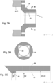
Fig. 3A is a front view of the support member; -
Fig. 3B is a side view of the support member; -
Fig. 3C is an enlarged view of part A inFig. 3A ; -
Fig. 4 is a front view showing a part of an injection unit according to a first modification; -
Fig. 5A is a front view of a support member according to a second modification; and -
Fig. 5B is a side view of a support member according to a second modification. - An embodiment of
injection unit 3 andinjection molding machine 1 equipped withinjection unit 3 according to the present invention will be described with reference to the drawings.Fig. 1 shows a schematic front view ofinjection molding machine 1 according to this embodiment.Injection molding machine 1 generally comprisesmold clamping unit 2 that clamps a mold, andinjection unit 3 that heats and melts the material to be injected and injects the material. In the following description, the axial direction or direction of movement ofscrew 33 will be referred to as the X-direction. The X-direction is parallel to the horizontal direction. The direction in whichscrew 33 moves towardmovable platen 24, or the direction in which the material is ejected, is referred to as the +X-direction, and the direction in whichscrew 33 moves away frommovable platen 24 is referred to as the -X-direction. The vertical direction is called the Z-direction. - Mold
clamping unit 2 comprises fixedplaten 22 fixed onbed 21 and on which fixed mold M1 is mounted,mold clamping housing 23 that is slidable onbed 21, andmovable platen 24 that can slide onbed 21 and on which movable mold M2 is mounted. Fixedplaten 22 andmold clamping housing 23 are connected by a plurality oftie bars 25. Moldclamping mechanism 26 for opening and closing the mold is provided betweenmovable platen 24 andmold clamping housing 23. By closing the mold, a cavity (not shown) is formed between fixed mold M1 and movable mold M2.Mold clamping mechanism 26 comprisestoggle mechanism 27 andmold clamping motor 28 that drivestoggle mechanism 27. Although not shown,mold clamping mechanism 26 may be a direct pressure mold clamping mechanism, that is, a hydraulic mold clamping cylinder. -
Injection unit 3 is provided onbase 31.Injection unit 3 comprisescylinder 32,screw 33 at least a part of which is housed insidecylinder 32, anddrive mechanism 34 that drivesscrew 33.Screw 33 is rotationally driven bydrive mechanism 34 and is also driven in the X-direction. That is,screw 33 is rotatable around the X-direction axis C ofscrew 33 and movable in the axial direction of cylinder 32 (X-direction).Drive mechanism 34 is covered with a cover (not shown). Hopper 36 for supplying material to be injected is provided near the end ofcylinder 32 in the -X-direction. -
Injection nozzle 37 is provided at the tip ofcylinder 32 in the +X-direction to abut against fixed mold M1 and supply injection material to the cavity.Injection unit 3 includesnozzle touch mechanism 38.Nozzle touch mechanism 38 movesinjection unit 3 forward, thereby causinginjection nozzle 37 to touch sprue bush M3 of fixed mold M1. Nozzletouch mechanism 38 connectsdrive mechanism 34 andfixed platen 22.Nozzle touch mechanism 38 is often configured with a hydraulic device. -
Fig. 2 is a front view showing a part ofinjection unit 3.Screw 33 is shown in a state of having moved to its limit in the +X-direction.Drive mechanism 34 comprisesdrive shaft 42 that drivesscrew 33 via connectingshaft 41,rotation drive unit 43 that rotatesdrive shaft 42 around axis C that is aligned in the X-direction, andaxial drive unit 44 that rotatesdrive shaft 42 in the axial direction (X-direction).Rotation drive unit 43 and theaxial drive unit 44 can be configured using a motor, a reduction device, etc., but can also be configured using a hydraulic device. Asdrive shaft 42 rotates, connectingshaft 41 connected to driveshaft 42 and screw 33 connected to connectingshaft 41 also rotate. When connectingshaft 41 moves in the axial direction (X-direction), driveshaft 42 andscrew 33 also move in the axial direction.Drive shaft 42 hasconnection hole 45 that receivesend region 41D of connectingshaft 41 in the -X-direction. - Connecting
shaft 41 connectsscrew 33 and driveshaft 42. Connectingshaft 41 comprisesconnection part 41A connected to screw 33,transition part 41B connected toconnection part 41A, andmain body part 41C connected to transitionpart 41B.Connection part 41A,transition part 41B, andmain body part 41C have circular cross sections. Sinceconnection part 41A surrounds the side surfaces ofend region 33B ofscrew 33 in the -X-direction,connection part 41A has an outer diameter larger than the outer diameter ofend region 33B. The outer diameter ofmain body part 41C is smaller than the outer diameter ofconnection part 41A.Transition part 41B is provided for the transition between different diameters ofconnection part 41A andmain body part 41C. - Connecting
hole 46 for receivingend region 33B is provided at the +X-direction end ofconnection part 41A. Splines are provided on the inner surface of connectinghole 46 and the side surface ofend region 33B. Sinceconnection part 41A is spline-connected to screw 33 in this manner, rotation of connectingshaft 41 with respect to screw 33 is prevented. -
End region 41D in the -X-direction ofmain body part 41C is supported by connectinghole 45 ofdrive shaft 42. The outer diameter ofend region 41D is the same as the outer diameter of the other portion ofmain body part 41C. Splines are provided on the inner surface of connectinghole 45 in the -X-direction and on the side surface ofend region 41D ofmain body part 41C. Since connectingshaft 41 is spline-connected to driveshaft 42 in this manner, rotation of connectingshaft 41 with respect to driveshaft 42 is prevented. The outer diameter ofmain body part 41C (endregion 41D) can be determined according to the inner diameter of connectinghole 45. - Inner restraining
member 47 is provided at the end in the +X-direction of connectingshaft 41 to prevent movement of connectingshaft 41 in the X-direction with respect to screw 33.Screw 33 comprises a cylindricalmain part 33A in whichflights 33C are formed, and acylindrical end region 33B located outside ofcylinder 32, and inner restrainingmember 47 is attached to screw 33 inend region 33B.Groove 48 is provided on the outer surface ofconnection part 41A of connectingshaft 41, and inner restrainingmember 47 includes claw part 47A that fits intogroove 48. - Outer restraining
member 49 is provided at a portion of connectingshaft 41 adjacent to driveshaft 42 to prevent movement of connectingshaft 41 in the X-direction with respect to driveshaft 42.Groove 50 is provided on the outer surface ofdrive shaft 42, and outer restrainingmember 49 hasclaw part 49A that fits intogroove 50. - Explanation next regards the reason for providing connecting
shaft 41.Injection molding machine 1 mainly comprises a mold clamping unit and an injection unit, but the mold clamping unit and the injection unit do not necessarily have a one-to-one correspondence. For example, one injection unit selected from a plurality of types of injection units may be combined with a certain mold clamping unit. In the case of a standard combination of an injection unit and a mold clamping unit, no special modification of the mold clamping unit and the injection unit is required regardless of which injection unit is selected. - On the other hand, depending on the specifications of the molded product, a user may choose a combination other than the standard combination of an injection unit and a mold clamping unit. For example, since a large-sized mold clamping unit is used for manufacturing large-sized molded products, the large-sized mold clamping unit is generally combined with an injection unit having a large injection volume. For this reason, a large mold clamping unit is typically combined with an injection unit with a large injection volume. However, when manufacturing a molded product that is large in plan but thin, a large-sized mold clamping unit is required but the use of an injection unit with a small injection volume may be preferable. In this case, after having selected an injection unit of the standard combination, screw 33 and
cylinder 32 may be replaced by equivalent components of an injection unit having a smaller injection volume. Since drive mechanism 34 (motor, etc.) of the injection unit has a sufficient margin with respect to the injection volume, no major problem arises regarding the material injection performance. - However, in an injection unit having a small injection volume, because
screw 33 andcylinder 32 are generally short in length, whenscrew 33 is directly connected to driveshaft 42, the tip ofcylinder 32 in the +X-direction is accordingly moved relatively far from the mold. Therefore, the distance thatcylinder 32 moves in the X-direction becomes longer. If this movement distance cannot be realized due to functional constraints ofnozzle touch mechanism 38 such as limitations on the stroke of a hydraulic cylinder,injection nozzle 37 will not be able to contact sprue bush M3 of the mold. Therefore, in order to compensate for the inadequate distance betweenscrew 33 andcylinder 32, connectingshaft 41 is connected to screw 33, andspacer member 51 that surrounds connectingshaft 41 is attached tocylinder 32. - The lengths of connecting
shaft 41 andspacer member 51 are not limited as long asinjection nozzle 37 can touch sprue bush M3, but the lengths ofscrew 33 andcylinder 32 of the selected standard combination of injection units are preferably determined to remain substantially unchanged. That is, if the screw length of the injection unit of the selected standard combination is S1, the length of connectingshaft 41 in the X-direction is S2, and the length of the replaced screw (screw 33 in this embodiment) is S3, it is preferable to determine S2 such that S1 = S2 + S3. Similarly, if the cylinder length of the injection unit of the selected standard combination is C1, the length ofspacer member 51 in the X-direction is C2, and the length of the replaced cylinder (cylinder 32 in this embodiment) is C3, it is preferable to determine C2 such that C1 = C2 + C3. - By setting the lengths of connecting
shaft 41 andspacer member 51 in this manner, the substantial screw length of connectingshaft 41 and screw 33 matches the screw length of the injection unit of the selected standard combination. Furthermore, the combined substantial cylinder length ofspacer member 51 andcylinder 32 matches the cylinder length of the injection unit of the selected standard combination. Therefore, parts of the injection unit of the selected standard combination, such asnozzle touch mechanism 38 and the running rail (not shown) ofinjection unit 3 provided onbase 31 can be used without alteration. -
Spacer member 51 is made of metal.Spacer member 51 is a generally cylindrical member that extends in the X-direction as a whole and encloses connectingshaft 41.Spacer member 51 comprises acylindrical base part 51A that is attached tocylinder 32, acylindrical body part 51B that is connected to basepart 51A, and acylindrical end part 51C that is connected tobody part 51B. These may be integrally formed or may be joined by bolts, welding, or the like. - The
injection unit 3 includessupport member 52.Support member 52 comprisesbush 53 fitted around connectingshaft 41 andattachment part 54 to whichbush 53 is attached.Attachment part 54 is a generally circular member when viewed from the X-direction, and its outer peripheral portion is fixed to endpart 51C ofspacer member 51 withbolts 56.Bush 53 is a cylindrical member and is fitted toattachment part 54 so as to be in contact withattachment part 54 around the entire circumference. Therefore, a member for fixingbush 53 toattachment part 54 is not required, and the structure ofsupport member 52 is simplified.Support member 52 allows rotation of connectingshaft 41 around the X-direction axis C, allows movement in the axial direction (X-direction), and supports connectingshaft 41 at least in the vertical direction Z. -
Bush 53 is preferably an oilless bush. Since there is no need to inject lubricating oil betweenbush 53 and connectingshaft 41, little maintenance is required. The material ofbush 53 may be either metal or resin. Examples of the resin material include tetrafluoroethylene, polyphenylene sulfide, polyetheretherketone, thermoplastic polyimide, polyamide, polyamideimide, and polyetherimide. Examples of the metal material include pure iron-based, iron-copper-based, iron-bronze-based, iron-carbon-graphite-based, bronze, and bronze-based sintered materials as specified in Japanese Industrial Standard Z2550: 2016 ("Sintered Metal Materials - Specifications"), cast iron with internal space impregnated with lubricating oil, and graphite-filled copper alloy having embedded lubricating oil and formed with a drilled cylindrical hole. - Since
support member 52 supports the weight of connectingshaft 41, it is possible to reduce or eliminate any inclination ofscrew 33 that is connected to connectingshaft 41. Since connectingshaft 41 is connected to screw 33, any tilting of connectingshaft 41 due to the weight of connectingshaft 41 will affectscrew 33. Ifscrew 33 tilts insidecylinder 32,screw 33 may come into contact with the inner wall ofcylinder 32 during rotation and/or movement ofscrew 33, and fine powder may be generated. If generated fine powder mixes with the injection material, there is a possibility that the fine powder will be mixed into the molded product. Furthermore, the heat generated by the contact betweenscrew 33 andcylinder 32 may cause abnormal heating and discoloration of the surrounding injection material. In transparent molded products such as light guide plates and lenses, fine powder and discolored parts are visible from the outside as defects such as black spots and yellowed parts and may have a significant impact on product yield. - Since
support member 52 is located betweenscrew 33 and driveshaft 42 and supports connectingshaft 41, any inclination of connectingshaft 41 will be reduced, whereby any inclination ofscrew 33 is reduced and any contact betweenscrew 33 andcylinder 32 is prevented. In order to reduce the inclination of connectingshaft 41,support member 52 is preferably installed near the middle betweenscrew 33 and driveshaft 42. However, since connectingshaft 41 moves in the -X-direction together withscrew 33 as shown by the broken lines inFig. 2 ,connection part 41A andtransition part 41B of connectingshaft 41 must be prevented from coming into contact withsupport member 52. For this reason,support member 52 is installed betweendrive shaft 42 and the position of maximum retraction oftransition part 41B in the -X-direction. - As shown in
Fig. 3C ,attachment part 54 includes holdingpart 55 that holds the tip ofbush 53 that is closer to screw 33 (the tip in the +X-direction). Holdingpart 55 has a generally cylindrical shape.Screw 33 and connectingshaft 41 move at high speed in the +X-direction during an injection process, and holdingpart 55 reduces the possibility thatbush 53 will be dragged in the +X-direction by connectingshaft 41 and detach fromattachment part 54 during the injection process. In order to prevent holdingpart 55 from coming into contact with connectingshaft 41, the height of holdingpart 55 is preferably slightly lower than the thickness ofbush 53. That is, inner diameter D1 of holdingpart 55 is preferably slightly larger than inner diameter D2 ofbush 53. - On the other hand, during a measurement process, screw 33 and connecting
shaft 41 move in the -X-direction at a lower speed than during the injection process. Since there is a little possibility thatbush 53 will detach fromattachment part 54 during the measurement process, there is less need to holdbush 53 byattachment part 54. Therefore, with the exception of holdingpart 55, the inner diameter D3 ofattachment part 54 is approximately equal to outer diameter D4 ofbush 53. - Similar to
Fig. 2 ,Fig. 4 shows a front view of a first modification ofinjection unit 3. In this modification, connectingshaft 41 has a constant diameter in section F in which supportmember 52 can face connectingshaft 41, this diameter being equal to the diameter ofconnection part 41A that connects withscrew 33. In other words, section F is included inconnection part 41A. InFig. 4 , screw 33 is at the position of maximum movement in the +X-direction. Whencylinder 32 and connectingshaft 41 move in the -X-direction from this state, inner restrainingmember 47 comes to the position indicated by the broken lines. For convenience, if it is assumed that connectingshaft 41 is fixed andsupport member 52 moves,support member 52 moves relative to connectingshaft 41 to the position indicated by the broken lines.Support member 52 is movable relative to connectingshaft 41 in this section F because connectingshaft 41 has a constant diameter in the section F between the position wheresupport member 52 is drawn with solid lines and the position wheresupport member 52 is drawn with broken lines. -
Support member 52 can therefore be installed closer to thescrew 33 side, that is, closer to the midpoint betweenscrew 33 and driveshaft 42, and any inclination of connectingshaft 41 can be further reduced. In this modification,support member 52 must be prevented from coming into contact with inner restrainingmember 47 at the position wherecylinder 32 is most retracted in the -X-direction. -
Figs. 5A and 5B show diagrams of a second modification similar to the configuration ofFigs. 3A and 3B . Sincesupport member 52 need onlysupport connecting shaft 41 at least in the vertical direction Z, the entire circumference of connectingshaft 41 need not be supported.Bush 53 does not have to be cylindrical. In this modification,bush 53 comprises only a lower semicircular part in the vertical direction Z, and accordingly,attachment part 54 also comprises only a lower half part. - The present disclosure can be applied to a method for modifying
injection molding machine 1. The structure of this embodiment can be realized by providingsupport member 52 andspacer member 51 in an injection unit that does not includesupport member 52 andspacer member 51 inFig. 2 . -
- 1
- injection molding machine
- 3
- injection unit
- 32
- cylinder
- 33
- screw
- 41
- connecting shaft
- 42
- drive shaft
- 51
- spacer member
- 52
- support member
- 53
- bush
- 54
- attachment part
- 55
- holding part
Claims (8)
- An injection unit (3) comprising:a cylinder (32);a screw (33) at least a part of which is housed inside the cylinder (32) and that is rotatable and movable in an axial direction of the cylinder (32);a drive shaft (42) that drives the screw (32);a connecting shaft (41) that connects the screw (33) and the drive shaft (42); anda support member (52) that is located between the screw (33) and the drive shaft (42), that allows rotation and movement in the axial direction of the connecting shaft (41), and that supports the connecting shaft (41) at least in a vertical direction.
- The injection unit (3) according to claim 1, further comprising a spacer member (51) that is connected to the cylinder (32) and that encloses the connecting shaft (41), wherein
the support member (52) includes a bush (53) fitted to the connecting shaft (41) and an attachment part (54) for the bush (53) attached to the spacer member (51). - The injection unit (3) according to claim 2, wherein the bush (53) is fitted into the attachment part (54).
- The injection unit (3) according to claim 2 or 3, wherein the attachment part (54) includes a holding part (55) that holds a tip of the bush (53) that is closer to the screw (33).
- The injection unit (3) according to any one of claims 2 to 4, wherein the bush (53) is an oilless bush.
- The injection unit (3) according to any one of claims 2 to 5, wherein the connecting shaft (41) has a constant diameter that is the same as a diameter of the connecting part that connects with the screw (33) in a section in which the support member (52) can face the connecting shaft (41).
- An injection molding machine (1) comprising a mold clamping unit (2) and the injection unit (3) according to claims 1 to 6.
- A method for modifying an injection molding machine (1) comprising:a cylinder (32);a screw (33) at least a part of which is housed inside the cylinder (32) and that is rotatable and movable in an axial direction of the cylinder (32);a drive shaft (42) that drives the screw (33);a connecting shaft (41) that connects the screw (33) and the drive shaft (42), the method comprising a step of:
attaching a support member (52) that is located between the screw (33) and the drive shaft (42), that allows rotation and movement in the axial direction of the connecting shaft (41), and that supports the connecting shaft (41) at least in a vertical direction.
Applications Claiming Priority (1)
| Application Number | Priority Date | Filing Date | Title |
|---|---|---|---|
| JP2023091435A JP2024173194A (en) | 2023-06-02 | 2023-06-02 | Injection unit, injection molding machine equipped with the same, and method for modifying an injection molding machine |
Publications (3)
| Publication Number | Publication Date |
|---|---|
| EP4470745A1 true EP4470745A1 (en) | 2024-12-04 |
| EP4470745B1 EP4470745B1 (en) | 2025-07-23 |
| EP4470745C0 EP4470745C0 (en) | 2025-07-23 |
Family
ID=91247487
Family Applications (1)
| Application Number | Title | Priority Date | Filing Date |
|---|---|---|---|
| EP24177753.1A Active EP4470745B1 (en) | 2023-06-02 | 2024-05-23 | Injection unit, injection molding machine equipped with the same, and method for modifying an injection molding machine |
Country Status (4)
| Country | Link |
|---|---|
| US (1) | US20240399634A1 (en) |
| EP (1) | EP4470745B1 (en) |
| JP (1) | JP2024173194A (en) |
| CN (1) | CN119058007A (en) |
Families Citing this family (1)
| Publication number | Priority date | Publication date | Assignee | Title |
|---|---|---|---|---|
| US20240149513A1 (en) * | 2021-01-29 | 2024-05-09 | Fanuc Corporation | Injection device |
Citations (4)
| Publication number | Priority date | Publication date | Assignee | Title |
|---|---|---|---|---|
| US7165966B2 (en) * | 2002-05-31 | 2007-01-23 | Toshiba Kikai Kabushiki Kaisha | Injection molding machine |
| EP2535162B1 (en) * | 2011-06-17 | 2014-08-06 | Sumitomo Heavy Industries, Ltd. | Injection moulding device and method of aligning a drive shaft with the injection screw |
| US20160075065A1 (en) * | 2013-03-28 | 2016-03-17 | Sodick Co., Ltd. | Screw position adjustment device for injection molding machine |
| JP2020104370A (en) | 2018-12-27 | 2020-07-09 | 日精樹脂工業株式会社 | Injection molding device |
-
2023
- 2023-06-02 JP JP2023091435A patent/JP2024173194A/en active Pending
-
2024
- 2024-05-16 US US18/666,751 patent/US20240399634A1/en active Pending
- 2024-05-23 EP EP24177753.1A patent/EP4470745B1/en active Active
- 2024-05-30 CN CN202410690828.8A patent/CN119058007A/en active Pending
Patent Citations (4)
| Publication number | Priority date | Publication date | Assignee | Title |
|---|---|---|---|---|
| US7165966B2 (en) * | 2002-05-31 | 2007-01-23 | Toshiba Kikai Kabushiki Kaisha | Injection molding machine |
| EP2535162B1 (en) * | 2011-06-17 | 2014-08-06 | Sumitomo Heavy Industries, Ltd. | Injection moulding device and method of aligning a drive shaft with the injection screw |
| US20160075065A1 (en) * | 2013-03-28 | 2016-03-17 | Sodick Co., Ltd. | Screw position adjustment device for injection molding machine |
| JP2020104370A (en) | 2018-12-27 | 2020-07-09 | 日精樹脂工業株式会社 | Injection molding device |
Also Published As
| Publication number | Publication date |
|---|---|
| EP4470745B1 (en) | 2025-07-23 |
| US20240399634A1 (en) | 2024-12-05 |
| EP4470745C0 (en) | 2025-07-23 |
| CN119058007A (en) | 2024-12-03 |
| JP2024173194A (en) | 2024-12-12 |
Similar Documents
| Publication | Publication Date | Title |
|---|---|---|
| EP4470745B1 (en) | Injection unit, injection molding machine equipped with the same, and method for modifying an injection molding machine | |
| KR20020050214A (en) | Injection molding machine | |
| US6364650B1 (en) | Injection apparatus with load detection between support members | |
| CN100540183C (en) | Improved injection nozzle of metal material injection moulding machine | |
| CN108688090B (en) | Injection molding machine | |
| RU2268807C2 (en) | Injection unit | |
| EP1741538B1 (en) | Injection unit of injection molding machine | |
| CN110253843B (en) | Mold opening and closing device | |
| EP2535162B1 (en) | Injection moulding device and method of aligning a drive shaft with the injection screw | |
| KR20180102512A (en) | Injection molding machine | |
| KR100897197B1 (en) | Injection device | |
| CN113459385B (en) | Injection molding machine | |
| JP4035123B2 (en) | Injection molding machine | |
| JP3262224B2 (en) | Electric injection molding machine | |
| JP2001248706A (en) | Driving device | |
| US20230382028A1 (en) | Injection apparatus and method of manufacturing resin body | |
| JP3321431B2 (en) | Injection mechanism of electric injection molding machine | |
| KR100907171B1 (en) | Hybrid injection device | |
| WO2022210789A1 (en) | Injection device | |
| CN117921970A (en) | Injection molding machine | |
| EP4737027A1 (en) | Backflow prevention device and injection apparatus provided with same | |
| KR100783651B1 (en) | Mold apparatus, molded products, molding method thereof, molding machine and bush | |
| JP2017170710A (en) | Preplasticating injection apparatus | |
| JP3236823B2 (en) | Injection molding machine | |
| KR20220166989A (en) | Injection molding machine |
Legal Events
| Date | Code | Title | Description |
|---|---|---|---|
| PUAI | Public reference made under article 153(3) epc to a published international application that has entered the european phase |
Free format text: ORIGINAL CODE: 0009012 |
|
| STAA | Information on the status of an ep patent application or granted ep patent |
Free format text: STATUS: THE APPLICATION HAS BEEN PUBLISHED |
|
| AK | Designated contracting states |
Kind code of ref document: A1 Designated state(s): AL AT BE BG CH CY CZ DE DK EE ES FI FR GB GR HR HU IE IS IT LI LT LU LV MC ME MK MT NL NO PL PT RO RS SE SI SK SM TR |
|
| STAA | Information on the status of an ep patent application or granted ep patent |
Free format text: STATUS: REQUEST FOR EXAMINATION WAS MADE |
|
| 17P | Request for examination filed |
Effective date: 20250116 |
|
| GRAP | Despatch of communication of intention to grant a patent |
Free format text: ORIGINAL CODE: EPIDOSNIGR1 |
|
| STAA | Information on the status of an ep patent application or granted ep patent |
Free format text: STATUS: GRANT OF PATENT IS INTENDED |
|
| INTG | Intention to grant announced |
Effective date: 20250402 |
|
| GRAS | Grant fee paid |
Free format text: ORIGINAL CODE: EPIDOSNIGR3 |
|
| GRAA | (expected) grant |
Free format text: ORIGINAL CODE: 0009210 |
|
| STAA | Information on the status of an ep patent application or granted ep patent |
Free format text: STATUS: THE PATENT HAS BEEN GRANTED |
|
| AK | Designated contracting states |
Kind code of ref document: B1 Designated state(s): AL AT BE BG CH CY CZ DE DK EE ES FI FR GB GR HR HU IE IS IT LI LT LU LV MC ME MK MT NL NO PL PT RO RS SE SI SK SM TR |
|
| RAP3 | Party data changed (applicant data changed or rights of an application transferred) |
Owner name: THE JAPAN STEEL WORKS, LTD. |
|
| REG | Reference to a national code |
Ref country code: GB Ref legal event code: FG4D |
|
| REG | Reference to a national code |
Ref country code: CH Ref legal event code: EP |
|
| REG | Reference to a national code |
Ref country code: IE Ref legal event code: FG4D |
|
| U01 | Request for unitary effect filed |
Effective date: 20250723 |
|
| U07 | Unitary effect registered |
Designated state(s): AT BE BG DE DK EE FI FR IT LT LU LV MT NL PT RO SE SI Effective date: 20250729 |
|
| PG25 | Lapsed in a contracting state [announced via postgrant information from national office to epo] |
Ref country code: IS Free format text: LAPSE BECAUSE OF FAILURE TO SUBMIT A TRANSLATION OF THE DESCRIPTION OR TO PAY THE FEE WITHIN THE PRESCRIBED TIME-LIMIT Effective date: 20251123 |
|
| PG25 | Lapsed in a contracting state [announced via postgrant information from national office to epo] |
Ref country code: NO Free format text: LAPSE BECAUSE OF FAILURE TO SUBMIT A TRANSLATION OF THE DESCRIPTION OR TO PAY THE FEE WITHIN THE PRESCRIBED TIME-LIMIT Effective date: 20251023 |
|
| PG25 | Lapsed in a contracting state [announced via postgrant information from national office to epo] |
Ref country code: HR Free format text: LAPSE BECAUSE OF FAILURE TO SUBMIT A TRANSLATION OF THE DESCRIPTION OR TO PAY THE FEE WITHIN THE PRESCRIBED TIME-LIMIT Effective date: 20250723 |
|
| PG25 | Lapsed in a contracting state [announced via postgrant information from national office to epo] |
Ref country code: GR Free format text: LAPSE BECAUSE OF FAILURE TO SUBMIT A TRANSLATION OF THE DESCRIPTION OR TO PAY THE FEE WITHIN THE PRESCRIBED TIME-LIMIT Effective date: 20251024 |
|
| PG25 | Lapsed in a contracting state [announced via postgrant information from national office to epo] |
Ref country code: PL Free format text: LAPSE BECAUSE OF FAILURE TO SUBMIT A TRANSLATION OF THE DESCRIPTION OR TO PAY THE FEE WITHIN THE PRESCRIBED TIME-LIMIT Effective date: 20250723 |
|
| PG25 | Lapsed in a contracting state [announced via postgrant information from national office to epo] |
Ref country code: RS Free format text: LAPSE BECAUSE OF FAILURE TO SUBMIT A TRANSLATION OF THE DESCRIPTION OR TO PAY THE FEE WITHIN THE PRESCRIBED TIME-LIMIT Effective date: 20251023 |
|
| PG25 | Lapsed in a contracting state [announced via postgrant information from national office to epo] |
Ref country code: ES Free format text: LAPSE BECAUSE OF FAILURE TO SUBMIT A TRANSLATION OF THE DESCRIPTION OR TO PAY THE FEE WITHIN THE PRESCRIBED TIME-LIMIT Effective date: 20250723 |
|
| PG25 | Lapsed in a contracting state [announced via postgrant information from national office to epo] |
Ref country code: SM Free format text: LAPSE BECAUSE OF FAILURE TO SUBMIT A TRANSLATION OF THE DESCRIPTION OR TO PAY THE FEE WITHIN THE PRESCRIBED TIME-LIMIT Effective date: 20250723 |
|
| PG25 | Lapsed in a contracting state [announced via postgrant information from national office to epo] |
Ref country code: CZ Free format text: LAPSE BECAUSE OF FAILURE TO SUBMIT A TRANSLATION OF THE DESCRIPTION OR TO PAY THE FEE WITHIN THE PRESCRIBED TIME-LIMIT Effective date: 20250723 |
|
| PG25 | Lapsed in a contracting state [announced via postgrant information from national office to epo] |
Ref country code: SK Free format text: LAPSE BECAUSE OF FAILURE TO SUBMIT A TRANSLATION OF THE DESCRIPTION OR TO PAY THE FEE WITHIN THE PRESCRIBED TIME-LIMIT Effective date: 20250723 |